1
OWNER'S
MANUAL
MODEL NO=
536.884811
CRAFI" SMAH®
Caution'.
Read and Follow
all Safety Rules
and Instructions
Before Operating
This Equipment
5 HORSEPOWER
23" DUAL STAGE
TRAC=PLUS
OPTIONAL ELECTRIC
SNOW THROWER
•
°
•
°
°
START
Assembly
Operation
Maintenance
Service and Adjustments
Repair Parts
SEARS, ROEBUCK AND Co., Chicago, IL. 60684 U.S.A.
SAFETY RULES
CAUTION:
ALWAYS
DISCONNECT
SPARK
PLUG
WIRE
AND
PLACE
WIRE
WHERE
IT CANNOT
CONTACT
SPARK
PLUG TO
PREVENT
ACCIDENTAL
STARTING
WHEN
SETTING-UP,
TRANSPORTING,
ADJUSTING
OR MAKING
REPAIRS.
A
IMPORTANT
SAFETY
STANDARDS
REQUIRE
OPERATOR
PRESENCE
CONTROLS
TO
MINIMIZE
THE RISK OF INJURY.
YOUR SNOW
THROWER
IS EQUIPPED
WITH SUCH CONTROLS.
DO NOT
ATTEMPT
TO DEFEAT
THE
FUNCTION
OF THE
OPERATOR
PRESENCE
CONTROL
UNDER ANY CIRCUMSTANCES.
BEFORE USE
FUEL SAFETY
•
Read the owner's manual carefully. Be thoroughly familiar with the controls and the proper
use of the snow thrower. Know how to stop the
snow thrower
and disengage
the controts
quickly°
•
Handle fuef with care; it is highly flammable.
•
•
Use an approved fuel container.
Check fuel supply before each use, allowing
space for expansion as the heat of the engine
and/or sun can cause fuel to expand.
Do not operate the snow thrower without wearing adequate
winter outer garments.
Wear
footwear that will improve footing on slippery
surfaces.
•
Fillfueltankoutdoorswith
fill fuel tank indoors.
•
Replace fuel tank cap securely
spilled fuel.
Never remove fuel tank cap or add fuel to a
running engine or hot engine.,
Never store fuel or snow thrower with fuel in the
•
•
Keep the area of operation clear of all persons,
particularly small children, and pets.
•
=
Thoroughly inspect the area where the snow
thrower is to be used and remove all doormats,
•
tank inside
sleds, boards, wires, and other foreign objects.
•
Use only attachments
and accessories
approved by the manufacturer of the Snowthrower
(such as tire chains, electric start kits, etc.,)
•
Never operate the snow thrower without good
visibility ortight. Always be sure of your footing,
and keep a firm hold on the handles° Walk;
never run.
•
This snow thrower is for use on sidewalks,
driveways,
and other ground level surfaces.
CAUTION should be exercised while using on
steep sloping surfaces. DO NOT USE SNOW
THROWER
ON
SURFACES
ABOVE
GROUND
or other such structures
or
=
Check shear bolts and other bolts at frequent
intervals for proper tightness to be sure the
snow thrower is in safe working condition_
•
Disengage all clutches and shift into neutral
before starting the engine.,
=
•
fumes
may
•
Never allow children or young teenagers to
operate the snow thrower and keep them away
while it is operating.
Never allow adults to
operate the snow thrower without proper' instruction. Do not carry passengers_
•
Always wear safety glasses or eye shields
during operation orwhile performing an adjustment or repair to protect eyes from foreign
objects that may be thrown from the snow
thrower.
•
Exercise extrerne caution when operating on
or crossing gravel drives, walks, or roads. Stay
alert for hidden hazards or traffic.
•
Do not put hands or feet near or under rotating
parts. Keep clear of the discharge opening at
all times.
•
Exercise caution to avoid slipping or falling, especially when operating in reverse°
•
Do not clear snow across the face of slopes.
Exercise caution when changing direction on
slopes. Do not attempt to clear steep slopes.
•
Never operatethe snowthrowerwithout
proper
guards, plates or other safety protective devices in place.
LEVEL such as roofs of residences,
garages, porches
buildings.
where
and wipe up
reach an open flame or spark°
OPERATING SAFETY
Use extension cords and receptacles as specified by the manufacturer
for all snow throwers
with electric drive motors or electric starting
motors.
•
of a building
extreme care. Never
Adjust the snow thrower height to clear gravel
or crushed rock surface.
Let engine and snow thrower adjust to outdoor
temperatures
before starting to clear snow.
2
SAFETY RULES
o
®
Never operate the snow thrower near glass enclosures,
automobiles,
window wells, dropoffs, and the like without proper adjustment of
the snow discharge angle. Keep children and
pets away.
e
Never operate the snow thrower at high transport speeds on slippery surfaces. Look behind
and use care when backing.
o
Never direct discharge at bystanders
anyone in front of the snow thrower°
e
Do not run the engine indoors, except when
starting the engine and for transporting
the
snow thrower in or out of the building. Open the
outside doors; exhaust fumes are dangerous
(containing CARBON MONOXIDE, an ODORLESS and DEADLY GAS).
•
REPAIR/ADJUSTMENTS
®
Take all possible precautions when leaving the
snow thrower
unattended.
Disengage
the
auger/impeller,
shift to neutral, stop engine,
and remove key°
Do not overload the machine capacity by attempting to clear snow at too fast a rate.
SAFE STORAGE
o
o
After striking a foreign object, stop the engine
(motor), remove the wire from the spark plug,
disconnect the cord on electric motors, thoroughly inspect the snow thrower for any damage, and repair the damage before restarting
and operating the snow thrower.
If the snow thrower should start to vibrate
abnormally, stop the engine (motor) and check
immediately for the cause. Vibration is generally a warning of trouble.
or allow
o
Stop the engine (motor) whenever you leave
the operating position, before unclogging the
auger/impeller
housing or discharge
guide,
and when making any repairs, adjustments, or
inspections.
®
When cleaning, repairing, or inspecting, make
certain the auger/impeller
and all moving parts
have stopped. Disconnect the spark plug wire
and keep the wire away from the plug to
prevent accidental starting.
o
Never attempt to make any adjustments while
the engine is running (except when specifically
recommended
by manufacturer).
e
Maintain or replace safety and instruction
labels, as necessary_
Run the snow thrower a few minutes after
•
o
SAFETY
Always referto owner's manual instructions for
important details if the snow thrower is to be
stored for an extended period.
Disengage power to the auger/impeller
when
snow thrower is transported or not in use.
e
throwing snow
auger/impeller_
Never store the snow thrower with fuel in the
to prevent
fuel tan k inside a building where ignition sou rces
are present such as hot water and space
heaters, clothes dryers, and the like. Allow the
engine to cool before storing in any enclosure.
CAUTION: AVOID INJURY FROM ROTATING AUGER. KEEP
HANDS, FEET, AND
CLOTHING AWAY! ..._
CHARGE CHUTE!
LOOK
_
FOR THIS SYMBOL
IMPORTANT
SAFETY
MEANS--ATTENTION!!!
i
TO POINT OUT I
PRECAUTIONS,
ITI
BECOME
ALERT...I
........
YOUR
SAFETY,IS I,NVOLVED.
3
I
freeze-up
of the
PRODUCT
CONGRATULATIONS
on your purchase of a Sears
Craftsman Snow Thrower. It has been designed, engineered and manufactured to give you the best possible
dependability and performance°
Should you experience any problem you cannot easily
remedy, please contact your nearest Sears Service Center/Department. We have competent, well-trained technicians and the proper tools to service or repair this unit.
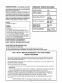
SPECIFICATIONS
l llll
u.,,i
HORSE
Please read and retain this manual. The instructions will
enable you to assemble and maintain your snow thrower
properly. Always observe the "SAFETY RULES°"
,,,
POWER:
i ill i
5 hp
DISPLACEMENT:
12.04
cu. in.
GASOLINE
2 quarts
Unleaded
Hi,
CAPACITY:
iiu
... H..i
SAE 10W-30
OIL (21 oz. Capacity):
(5w. 30)
MODEL
NUMBER 536884811
SPARK
SERIAL
NUMBER
DATE OF
PURCHASE
PLUG :
Champion
J8C
(GAP .030 in.)
VALVE CLEARANCE:
Intake: .010 In.
Exhaust: .010 In.
THE MODEL AND SERIAL NUMBERS WILL BE
FOUND ON A DECAL ATTACHED TO THE REAR
OF THE SNOW THROWER HOUSING.
YOU SHOULD RECORD BOTH SERIAL NUMBER
AND DATE OF PURCHASE AND KEEP IN A SAFE
PLACE FOR FUTURE REFERENCE
ii
MAINTENANCE
ill
AG REEMENT
A Sears Maintenance Agreement is available on this
product. Contact your nearest Sears Store for details.
CUSTOMER
RESPONSIBILITIES
• Read and observe the safety ruleSo
• Follow a regular schedule in maintaining, caring for and using your snow thrower.
• Follow the instructions under "Maintenance" and "Storage" sections of this owner's manual.
TWO YEAR LIMITED WARRANTY ON CRAFTSMAN
SNOW THROWER
For two years from the date of purchase, when this Craftsman Snow Thrower is maintained, lubricated
and tuned-up according to the instructions in the owner's manual, Sears will repair, free of charge, any
defect in material and workmanship.
If this Craftsman Snow Thrower is used for'commercial or rental purposes, this warranty applies for only
90 days from the date of purchase
This warranty does not cover the following:
:_
• Expendable items which become worn during normal use, such as spark plugs, tire chains, drive belts
and shear pins.
Repairs necessary because o! operator abuse or negligence, including bent crankshafts and the failure
to maintain the equipment according to the instructions contained in the owner's manual.
WARRANTY SERVICE IS AVAILABLE BY RETURNING THE CRAFTSMAN SNOW THROWER TO
THE NEAREST SEARS SERVICE CENTER!DEPARTMENT 1NTHE UNITED STATES. THIS WARRANTY APPLIES ONLY WHILE THIS PRODUCT IS IN USE IN THE UNITED STATES..
This warranty gives you specific legal rights, and you may also have other rights which may vary from
state to state.
SEARS, ROEBUCK AND CQ Department 731CR-W Sears Tower, Chicago, IL 60684
ii.H......,
4
i i i i.ll
J i i/u JliiJ.J
Hill
ii.Jll
i jj ii J i
i
TABLE OF CONTENTS
SAFETY RULES .....................................................
2,3
PRODUCT SPECIFICATIONS
...........................4
CUSTOMER
RESPONSIBILITIES
.....................
4
WARRANTY ...............................................................
4
TABLE OF CONTENTS ...................................... 5
INDEX ...........................................................................
5
ASSEMBLY ......................................................................
6-9
OPERATION .............................................. 10-t 4
MAINTENANCE
....................................................
15-16
SERVICE AND ADJUSTMENTS
...............! 7-23
STORAG E ................................................................
24
SERVICE RECOMMENDATIONS
.....................
25
TROUBLE SHOOTING .....................................26
REPAIR PARTS (SNOW THROWER) .....28-36
REPAIR PARTS (ENGINE) ..............................
37-40
PARTS ORDERING/SERVICE
.......Back Cover
INDEX
A
F
Operation:
Adjustment:
Engine Controls .........................
10, 11, 13
Fuel, Type .......................................................
4, 12
Auger Drive Belt ..................................
18, 19
Operating Snow Thrower,,, 11, 12, 14
Fuel, Storage .....................................................
I2, 24
Belts ...............................................................
18-20
Friction Wheel:
Operating Tips .............................................
14
Belt Guide ................................................................
20
Adjustment ....................................................
20
Starting the Engine ....................................
13
Cables ......................................................................
18
Snow Thrower Controls .......10-12, I4
Replacement ...................................................
21
Carburetor .....................................................
23
G
Weight Transfer System .....................
12
Gears:
Friction Wheel ............................................
20
P
Scraper Bar ...................................................
17
Auger Gear Box ............................
15, 16
Pads .........................................................
28-40
Spark Plug ......................................................
23
Hex Shaft .....................................................
t5, 16
Track ...............................................................
22
H
Primer Button ..................................
10, 11, 13
R
Track and Auger Drive Belts ...............
I8
Handle, Upper and Lower ..........................
7
Assembly:
Repair/Replacem ent Parts .............28-40
Height Adjust Skids ......................................
7, 17
Replacements:
Crank Assembly ..................................8
Hex Shaft .....................................................
15, 16
Shifter Lever ...............................................
9
I
Auger Shear Bolt ................................
22
Belts ................................................................
19.20
Skid Height Adjustment ...................
7, 17
Ignition, Key .................................
!0, 11, t3
Friclion Wheel ....................................21
index ..................................................................
5
Unpacking .........................................................
7
B
S
L
Belts:
Levers:
Safety Rules ..................................................
2-3
Service and Adjustments:
Adjust Belts ..................................................
18
Auger Drive Clutch ........................
10, 11
Auger Housing Height .........................
17
Belt Guide Adjustment .................... 20
Choke .........................................
10, tl, 13
Belt Maintenance ...................................
t5
Auger Shear Bolt ..............................22
Shifter .....................................................
9, 11
Belts .....................................................
18-20
Replace Belts ..................................
tg, 20
Throttle Control ...........................
10, 11, t3
Belt Guide ...........................................20
C
Traction Drive Olutch ....................
10, 11
Cables,Clutch ................................................
7, 9
Lubrication:
Belt Replacements .................. t9, 20
Cable .......................................................
18
Carburetor: .................................................
23, 24
Auger Gear Box ....................................
16
Crank ..........................................................
17
Chain .......................................................................
15
Auger Shaft .......................................................
15
Carburetor ...........................................
23
Choke ................................................
I O, 11, 13
Chain and Sprockets ...............................
15
Friction Wheel ......................................
20, 21
Clutch, Levers ...........................................
1O, t 1
Chart ............................................................
25
Controls:
Scraper Bar ..........................................
17
Engine ...................................................
12, 16
Shear Bolt ..................................................
22
Engine ................................................
10, 11, 13
Hex Shaft and Gears ...........................
15, 16
Snow Thrower ...................
10, t!, 12, 14
Weight Transfer System ........................
15
Spark Plug ......................................................
23
Track ..........................................................
22
Crank:
M
Service Recommendations ......................
25
Maintenance:
Adjusting Rod ..................................
8, 17
Spark Plug ..............................................
I6, 23
Assembly .......................................................
8
Agreement .......................................................
4
Specifications ...........................................4
Operation ..........................................................
t1
Auger Gear Box ..................................................
16
Speed Governor ............................... 23
Oustomer Responsibilities ..........................
4
Auger Shaft .....................................................
15
D
Starting the Engine .............................. 13
Chain and Sprockets ...............................
t5
Stopping the Engine ..................... 11, 13
Drive, Auger ....................................................
11
Engine .................................................................
t6
Drive, Track ..............................................
11
General Recommendations .............i5
Stopping the Snow Thrower .............. 11
Deflector, Snow Chute ................................
11
Hex Shaft and Gears ...............................
15
Shipping Carton .................................
6, 7
Skid Height ..................................... 7, 17
Weight Transfer System ..................15
Shifter Lever .................................. 9-11
E
O
Shear Bolts ...........................................22
Engine:
Oil;
Storage .......................................
24
Control .............................................
t0, 1I, 13
Engine ............................................
4, 12, 16
T
Oil Cap ...........................................................
! 2, 16
Extreme Cold Weather ...............12, 16
Table of Contents ........................................
5
Oil Change .........................................................
16
Storage .................................................24
Oi! Level .................................................
12, 16
Trouble Shooting Chart .................... 26
Type .........................................4, 12, t6
Oil Type ..........................................
4, 12, 16
Tools for Assembly .....................................
6
Track Drive Belt .............................18, 20
Speed Governor .......................................
23
Track Adjustment ..................................
22
Starting the Engine ................................
I3
W
Storage ..........................................................
24
Warranty .....................................................
4
Weight Transfer System ............. 12, 15
ASSEMBLY
THIS SNOW THROWER IS EQUIPPED WITH "TRAC-PLUS"
AND ONLY
MOVES EFFECTIVELY WHEN ENGINE IS RUNNING
if your snow thrower must be moved without the aid of the engine, it will be easier' to pull the snow thrower backward by the handles, rather than pushing.
On start up, the track drive system may be tight and will loosen up as the snow thrower is used. After first use,
check the track for tension and adjust if necessary_ See the Track Adjustment paragraph in the Service and Adjustments section of this manual. Check track adjustment and fasteners regularly.
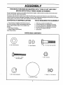
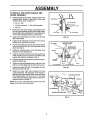
CONTENTS
OF SHIPPING
CARTON
TOOLS REQUIRED FOR ASSEMBLY
1 - Snow thrower completely assembled except for
the crank assembly, shifter lever assembly and knob,
and the upper handle, which is in the folded down
position.
1 - Parts Bag Containing:
1 - Owner's Manual (Not Shown)
Parts Shown Below:
t
2
2
2
1
1
- Knife (to cut carton and plastic ties)
- 1/2 inch Wrenches (or adjustable wrenches)
- 9/16 inch Wrenches (or adjustable wrenches)
- 3/4 inch Wrenches (or adjustabte wrenches)
- Pair Pliers (to spread cotter pin)
- Screwdriver
PARTS BAG CONTENTS
2 - 3t8 In.Flat Washers
2 - Spare Spacers
1 - 3/8 - t6 x 2 inch Hex Head Bolt
Q
2- 1/4 - 20 x 1 - 3/4 In..
Hex Head Bolts
1 - 3/8 In..Hex Nut
1 - 3/8 tn.,Split Lockwasher
2 - Spare 1/4 - 20 Locknuts
1 - Knob With Threads
6
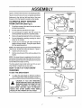
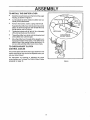
ASS
Figure i showsthe snowthrowerin
LY
the shipping position,,
LOWER HANDLE
Figure 2 shows the snow thrower completely assembled,,
Reference to the right and left hand side of the snow
thrower is from the operator's position at the handler
CRANK
ASSEMBLY
CLUTCH
CABLE
TO REMOVE SNOW THROWER
FROM CARTON
CONTROL
PANEL
(See Fig 1)
e
Cut all four corners of the carton from top to bottom
and lay the panels flat..
®
Cut the cable ties attached to the auger,,
e
Cut and discard the plastic ties that secure the
crank assembly and place the assembly aside,,
®
Remove the packing material from the control panelo
e
Cut and discard the packing securing the clutch
cables to the handles.
o
Loosen (do not remove) both botts securing the
upper and lower handles., Swing the upper handle
into the operating position.
HANDLE
ASSEMBLY
FIG. 1
NOTE: If the cables have become disconnected fromthe
clutch levers, reinstall the cables as shown in Figure 3.
®
Tighten both bolts securely..
e
Roll the snow thrower off the skid by pulling on the
handle.,
NOTE: This snow thrower is equipped with a track drive
and can be hard to push when the engine is not running
It is easier to pull the snow thrower backward if it must be
moved without the engine running
The drive system may be tight when you first use your
snow thrower tt loosens up as you use it
HOW TO SET UP YOUR SNOW
THROWER
FIG. 2
TO SET THE SKID HEIGHT
®
To adjust the skids height for different conditions,
see To Adjust Skids Height paragraph on page 17,,
i,
CAUTION:
IF YOU
ARE
REMOVING
DRIVE
LEVER
"Z" FITTING
SNOW FROM ANY ROCKY OR UNEVEN
SURFACES, RAISE THE FRONT OF THE
SNOW THROWER BY MOVING THE
SKIDS DOWN, THIS WILL HELP TO PREVENT
ROCKS AND OTHER DEBRIS FROM BEING
PICKED UP AND THROWN BY THE AUGER.
._"I'HI'H
I I I
,III
FIG. 3
7
EMo ,Y
TO INSTALL THE UPPER HANDLE
CRANK ASSEMBLY
o
AND
On the right side of the handle, install and secure the
following parts (found in parts bag) in the lower
handle hole as shown in figure 4A:
PJGHT HANDLE
1 - 3/8" x 2" bolt
2 - 3/8" flat washers & 1 - 3/8" split lockwasher
1 ° 3/8" nut
I
Remove the 3/8" nylon Iocknut and flatwasher from
tl_e "eye" bolt assembly (on the chute crank assembly) and adjust the remaining 3/8" nut and flatwasher
on the "eye" bolt about half way up the thread..
o
Install "eye" bolt through lower hole on the left hand
side of the handle.
0
Install the 3/8" flatwasher and the 3/8" nylon locknut
loosely on the "eye" bolt, as shown°
qll
Remove the plastic cap, the cotter pin and the washer
from the wormed end of the crank assembly and set
aside (See Fig. 5).
ADJUST NUTS TO MOVE
EYE BOLT IN OR OUT
LEFT HANDLE
•
Rotate the notched section of the discharge chute
toward the crank-adjusting rod_
•
Install the wormed end of the crank through the hole
in the adjusting rod and secure the end with the flat
washer and cotter pin, as shown in Fig. 5o
•
Bendtheendsofthecotterpinaroundtherod
install the plastic cap°
•
Tighten the eye bolt installed earlier, keep eye in line
with the rod while tightening the inside nut securely,
•
Tighten the outside 3/8" jam nut up against the other
3/8" jam nut (See Fig.. 4B).
•
Rotate the chute crank fully c!ockwise and fully
counter-clockwise. The discharge chute should rotate fully to the outer diameter of the worm and should
clear' approximately 1/8" (see Fig. 5), If the chute
crank needs to be adjusted, go to the Service and Adjustments section on page 17.
TIGHTEN _/8" JAM
NUT UP AGAINST
OTHER 3/_," JAM NUT
EYE BOLT
andre-
FIG. 4B
J
ii iiii
PLASTIC
CAP
/
....
,
,,,lllUiii
i Ji iJ
_
i1,11,,i,ii
iiiiii
i iii /
NOTCHED
,,b
,,
SECTION
COTTER
INCH CLEARANC
NOTE: Be sure the crank does not touch the side of the
engine or' the cover will be scratched.
FLATWASHER
1/2 INCH
CRANK ADJUSTING
ROD
FIG. 5
WORM
AS
TO INSTALL THE SHIFTER
LY
LEVER
®
Stand the snow thrower up on the frontof the auger
housing, as shown in Figure 6.
o
Cut the plastic tie which holds the shifter lever assembly to the shift bracket°
•
Remove the Iocknut, washer, spring and the bolt..
Reposition the shifter lever into the slot in the control
panel, as shown in Figure 6 and reinstall the bolt,
spring washer and the Iocknut.
®
•
•
Tighten the Iocknut until 1/8" to 3/16" (2 or 3 threads)
of the bolt protrude past the Iocknuto
Thread the shifter lever knob onto the threaded end
of the shifter lever until it is tight.
Move the shifter lever through all the speeds to ensure proper tension of the spring. If the shifter Iever
sticks in any of the notches, loosen the Iocknu[ 1/4
turn at a time until the shifter lever moves freely..
TO CHECK/ADJUST
CONTROL
CLUTCH
CABLES
The control cables attached to the auger clutch lever and
traction clutch lever may need to be adjusted before you
use your snow thrower.
For instructions on checking or adjusting the clutch
control cables, see To Adjust The Clutch Control Cables
paragraph on page 18.
FIG. 6
9
i,
illlJllJll
,i
i Ill
i,
ill
iiJlllllj
.l=
I
ill,,ll IJl
J;
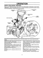
OPERATION
KNOW YOUR SNOW THROWER
......................................
READ THIS OWNER'S MANUALAND
SAFETY RULES BEFORE OPERATING YOUR SNOW
TH ROWER, Compare the illustrations with your snow thrower to familiarize yourself with the location of various
controls and adjustments.
Save this manual for future reference_
TRAC'fION DRIVE
LEVER
AUGER DRIVE
LEVER
SPEED SHIFTER
LEVER
CRANK
ASSEMBLY
CHUTE DEFLECTOR
WEIGHT
TRANSFER
DISCHARGE
CHUTE
BUTTON
IGNITION
KEY
RECOIL
STARTER
HANDLE
CHOKE CONTROL
THROTTLE
CONTROL
FIG. 7
L I
wmuw±
SEARS TRAC-PLUS SNOW THROWERS conform to the safety standards of the American National Standards
Institute.
AUGER DRIVE LEVER: Starts and stops the auge'r"and"
impeller (snow gathering and throwing)=
TRACTION DRIVE LEVER - Propels the snow thrower'
forward and in reverse.
WEIGHT TRANSFER PEDAL - Engage for heavy snow
conditions, to keep the snow thrower from climbing drifts
and hard-packed snow.. When released, it eases transport of the snow thrower°
HEIGHT ADJUST SKIDS - Adjusts the ground clearance of the auger housing.
IGNITION KEY - Must be inserted to start the engine.
RECOIL STARTER HANDLE - Starts the engine manuallyo
CHOKE CONTROL - Used to start a cold engine.
PRIMER BUTTON - Injects fuel directly into the carburetor manifold for fast starts in cold weather_.
SPEED SHIFTER LEVER - Selects the speed of the
snow thrower (6 speeds forward and 2 speeds reverse).
CRANK ASSEMBLY * Changes the direction of snow
throwing through the discharge chute.
CHUTE DEFLECTOR - Changes the distance the snow
is thrown°
DISCHARGE CHUTE - Changes the direction the snow
is thrown.
THROTTLE CONTROL - Controls the engine speed..
10
....
,,,
i
JI,,,MI
OP RATIO
The operation of any snow th rower can result in foreign objects being thrown int0 the
eyes, which can result in severe eye damage. Always wear safety glasses or eye
shields while operating the snow thrower°
We recommend standard safety glasses or Wide Vision Safety Mask for over your
glasses available at SEARS Retail or Catalog Stores,.
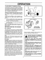
HOW TO USE YOUR SNOW
THROWER
TO CONTROL
WING KNOB
SNOW DISCHARGE
e
Turn the crank assembly to set the direction of the
snow throwing,.
o
Loosen the wing knob on the chute deflector and
move the deflector to set the distance.. Move the
deflector UP for more distance, DOWN for less
distance.. Then tighten the wing knob (See Fig, 8).
FIG. 8
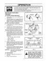
TO STOP YOUR SNOW THROWER
•
To stop throwing snow, release the auger drive
lever (See Fig.. 10).
o
To stop the track, release the traction drive lever,
o
To stop the engine, push the throttle control lever to
"STOP" and pull out the ignition key (See Fig. 9),.
TO MOVE FORWARD
e
PRIMER BUTTON
IGNITION
KEY
AND BACKWARD
To shift, release the traction drive lever and move
the speed shifter lever to the speed you desire.
Ground speed is determined by snow conditions.
Select the speed you desire by moving the speed
shifter lever intothe appropriate colored area on the
control panel
CHOKE'
CONTROl[.
RECOIL
STARTER
HANDLE
THROTTLE
CONTROL
FIG, 9
Red - Wet, Heavy, Slushy, Extra Deep
,,i i i= =ill 11
Amber- Moderate
.....
TRACTIONDRIVE
LEVER
White - Very Light
AUGERDRIVE
LEVER
OFF
Green - Transport only
®
Engage the traction drive lever (See Fig 10, left
hand). As the snow thrower starts to move, maintain
a firm hold on the handles, and guide the snow
thrower along the clearing path,. Do not attempt to
push the snow thrower,.
e
To move the snow thrower backward, move the
speed shifter lever into first or second reverse and
engage the traction drive lever (left hand).
IMPORTANT:
TO THROW
....... \
/
HAND
RIGHT
HAND
FIG. 10
DO NOT MOVETHE SPEED SHIFTER
LEVER WHILE THE TRACTION
LEVER iS DOWN.
CAUTION: READ OWNER'S MANUAL
BEFORE
OPERATING
MACHINE,
NEVER DIRECT DISCHARGE TOWARD
BYSTANDERS. STOP THE ENGINE BE*
FORE UNCLOGGING
DISCHARGE
CHUTE OR AUGER HOUSING AND
BEFORE LEAVING THE MACHINE,
SNOW
Push down the auger drive lever (See Fig. 10,
right hand)..
Release to stop throwing snow.
i,,i, i,
11
,, u
,,
................
OPERATION ....................
TO USE WEIGHT
TRANSFER
SYSTEM
In hard packed or heavy snow conditions, conventional
snow throwers tend to rideup and leave uneven mounds
of snow behind. For these conditions, your new tracked
snow thrower has a unique weight transfer system (See
Fig. 11) designed to minimize ride-up.
OFF
Stepping on the weight transfer pedal shins more weight
to the auger housing° This weight transfer keeps the
snow thrower in contact with the ground and reduces
ride-up,
ON
In lighter snow conditions or when transporting, you
should release the weight transfer system for easier
steering.
•
To use the weight transfer, hold the upper handle
firmly and push down on the weight transfer pedal
(See Fig. t 1) with the ball of your foot°
•
To release, pull up on the weight transfer pedalwith
the top of your foot.
FIG,11
OIL FILL CAPtDIPS3"tCK
NOTE: The weight transfer system will not work if the
auger housing height adjust skids are adjusted to the
highest position°
BEFORE STARTING
FILL/ADD
NOTE: OIL LEVEL
MUST BE BETWEEN
FULL AND ADD MARK
THE ENGINE
OIL:
The engine on this snow thrower was shipped without
oil Add oil before you start the engine. Remove the oil
fill cap/dipstick and fill the crank case to FULL line on
dipstick (about 2t ounces) (See Fig_ 12) with S.A,E
10 W-30 motor oil (or equivalent)., Do not overfill. Tighten
the fill capldipstick securely each time you check the oil
level
FIG,12
Never use engine or' carburetor cleaner products in the
fuel tank or permanent damage may occur,
,llllll
CAUTION: GASOLINE IS FLAMMABLE
AND CAUTION MUST BE USED WHEN
HANDLING OR STORING IT.
NOTE: SA.E 5W-30 motor oil may be used to make
starting easier in areas where temperature is consistently 20 ° F. or lower,
DO NOT FILL FUEL TANK WHILE SNOW
'THROWER IS RUNNING,WHEN IT IS HOT, OR
WHEN SNOW THROWER IS IN AN ENCLOSED
AREA.
FILL GAS:
WARNING: Experience indicates that alcohol blended
fuels (called gasohol or using ethanol or methanol) can
attract moisture which leads to separation and formation
of acids during storage_ Acidic gas can damage the fuel
system of an engine while in storage.
KEEP AWAY FROM OPEN FLAME OR AN ELECTRICAL SPARK AND DO NOT SMOKE WHILE
FILLING THE FUEL 'TANK.
To avoid engine problems, the fuel system should be
emptied before storage for 30 days or longer. Drain the
gas tank, start the engine and let it run until the fuel lines
and carburetor are empty. Use the carburetor bowl drain
to empty residual gasoline from the float chamber'
(Figure 39). Use fresh fuel next season_ (See Storage
instructions on page 24 for additional information)
NEVER FILL THE TANK COMPLETELY. FILL
THETANK TO WITHIN 1/4"- 112" FROMTHE TOP
TO PROVIDE SPACE FOR EXPANSION OF FUEL.
ALWAYS FILL FUEL TANK OUTDOORS AND
USE A FUNNEL OR SPOUT TO PREVENT SPILLING,
MAKE SURE TO WIPE UP ANY SPILLED FUEL
BEFORE STARTING THE ENGINE.
Fill the fue! tank with clean, fresh, unleaded grade automotive gasoline. Be sure that the container you pour the
gasoline from is clear] and free from rust or other foreign
particles., Never use gasoline that may be stale from long
periods of storage in the container.
STORE GASOLINE IN A CLEAN, APPROVED
CONTAINER AND KEEP THE CAP IN PLACE ON
THE CONTAINER.
12
OP
ATIO
CAUTION: NEVER RUN ENGINE INDOORS OR IN ENCLOSED, POORLY
VENTILATED AREAS. ENGINE EXHAUST CONTAINS CARBON MONOXIDE, AN ODORLESS AND DEADLY GAS.
KEEP HANDS, FEET, HAIR AND LOOSE CLOTHING AWAY FROM ANY MOVING PARTS ON
ENGINE AND SNOW THROWER.
WARNING: TEMPERATURE OF MUFFLER AND
NEARBY AREAS MAY EXCEED 150 ° F. AVOID
THESE AREAS.
DO NOT ALLOW CHtL DREN OR YOUNG TEENAGERS TO OPERATE OR BE NEAR SNOW
THROWER WHILE IT IS OPERATING.
.....
::
........
iGNITION
KEY
CHOKE
CONTROL
THROTTLE
WARM START
If restarling a warm engine after a short shutdown, rotate
choke to "OFF" instead of "FULL" and do not push the
primer button°
To stop engine, move the throttle control lever to
"STOP" position and remove key. Keep the key in a
safe place, The engine will not start without the key°
FROZEN STARTER
TO START ENGINE
If the starter is frozen and will not turn engine:
Be sure that the engine has sufficient oil. Before starting
the engine, be certain that you have read the following
information:
e
Pull as much rope out of the starter as possible.
®
Release the starter handle and let it snap back
against the starter
COLD START (See Fig. 13)
e
Be sure the auger and the traction drive levers are
in the disengaged "RELEASED" position,.
e
Move the throttle controt up to "FAST" position_
®
Remove the keys from the plastic bag. Insert one
key into the ignition slot,. Be sure it snaps intoplace..
DO NOT TURN KEY. Keep the second key in a
safe place..
e
Rotate choke control to "FULL" choke position.,
•
Press the primer button two or three times, while
keeping your finger over the vent hole on the primer
button.. Additional priming may be necessary for the
first start if the temperature is below 15° F_
e
Pull the starter handle rapidly.. Do not allow the
handle to snap back, but allow it to rewind slowly
while keeping a firm hold on the starter handle.
•
As the engine warms up and begins to operate
evenly, rotate the choke knob slowly to "OFF" position., If the engine falters, return to "FULL" choke,
then slowly move to "OFF" choke position_
If the engine still fails to start, repeal if continued attempts do not free starter, follow the electric starter procedures to start.
To help prevent possible freeze-up of recoil starter and
engine controls, proceed as follows after each snow
removal job.
NOTE: Allow the engine to warm up for a few minutes
because the engine will not deve!op full power until it
reaches operating temperature.
®
CONTROL
FIG.13
LL
TO STOP ENGINE
e
RECOIL
STARTER
HANDLE
Run the engine at or near the top speed when
throwing snow.
•t 3
®
With the engine running, pull the starter rope hard
with a continuous full arm stroke three or four times.
Pulling of starter rope will produce a loud clattering
sound_ This is not harmful to the engine or starter_
e
With the engine not running, wipe all snow and
moisture fromthe carburetorcover in area of control
levers.. Also move throttle control, choke control,
and starter handle several times.
:.
...:......
OPERATION
SNOW THROWING
TIPS
CAUTION: DO NOT ATTEMPT TO REMOVE ANY ITEM THAT MAY BECOME
LODGED IN AUGER WITHOUT TAKING
THE FOLLOWING PRECAUTIONS:
For maximum snow thrower efficiency, adjust ground
speed, not throttle° If the track slips, reduce forward
speed. The engine is designed to deliver maximum
performance at full throttle and should be run at this
power setting at all times.
• RELEASE AUGER
DRIVE LEVERS.
DRIVE AND TRACTION
O
Most efficient snow blowing is accomplished when
the snow is removed immediately after it falls
• MOVE THROTTLE
TION.
LEVER TO STOP POSI-
O
For complete snow removal, slightly overlap each
path previously taken.
e
• REMOVE (DO NOT TURN):!IGNITION KEY.
• DISCONNECT SPARK PLUG WIRE.
• DO NOT PLACE YOUR HANDS IN THE
AUGER OR DISCHARGE CHUTE, USE A
PRY BAR.
The snow should be discharged down wind whenever possible.
For normal usage, set the skids so that the scraper
bar is 1/8" above the skids. For extremely hardpacked snow surfaces, adjust the skids upward so
that the scraper bar touches the ground.
o
............................
On gravelor crushed rock surfaces, set the skids at
1-1/4" below the scraper bar (see To Adjust Skids
Height paragraph on page 17)_ Rocks and gravel
must not be picked up and thrown by tile machine
If the front of the snow thrower has a tendency to
raise, reduce the ground speed and engage the
weight transfer system_
After the snow blowing job has been completed,
allowthe engine to idlefor a few minutes, which will
melt snow and accumulated ice off the engine.
'_
o
Clean the snow throwerthoroughly
e
Remove ice and snow accumulation and all debris
from the entire snow thrower, and fluslt with water
(if possible) to remove all salt or other chemicals
Wipe snow thrower dr,,,.
after each use.
14
,, ,,,,,,
,,
L,LW
L,ll
I
TE ANCE
Ill
GENERAL
RECOMMENDATIONS
The warranty on this snow thrower does not cover items
that have been subjected to operator abuse or negligence,. To receive full value from the warranty, operator
must maintain snow thrower as instructed in this manual.,
Some adjustments will need to be made periodically to
properly maintain your snow thrower.,
All adjustments in the Service and Adjustments section of
this manual should be checked at least once each season,,
Jl
AFTER FIRST USE
e
e
i/
i
/ill
jill
FIG .14
Checkthe tracksfor tension and adjust if necessary
(See To Adjust Track paragraph on page 22)°
Check the track adjustment and fasteners regularly,,
WEIGHT
TRANSFER
Be sure that al_fasteners are tight.
,.J
PIVOT
AS REQUIRED
The following adjustments
than once each season.,
e
should be performed more
Auger and Track Drive Belts should be adjusted after
the first 2 to 4 hours of use and again about midseason and twice each season thereafter, See To
Adjust Belts paragraph on page 18,
e
i
ill illlll
IILllLI
FIG. 15
Alt screws and nuts should be checked often to make
sure they are tight, preferably after each use.,
SNOW THROWER
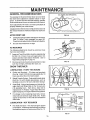
LUBRICATION
- EVERY TEN HOURS
o
Chains and Sprockets - Oil chains and sprockets
(See Fig. 14)with 10W-30 oil (or equivalent) after 10
hours use and at the end of each season,.
o
Weight Transfer System - Coat weight transfer plate
(See Fig,, 15) with clinging type grease, such as
lubriptate, every ten (10) hours and before storage_
@
Auger Shaft - Using a hand grease gun, lubricate the
auger shaft zerk fittings (See A, Fig 16) every ten
(10) operating hours,, Each time a shear bolt is
replaced (see To Replace Auger Shear Bolt paragraph on page 22), the auger shaft MUST be greased..
FIG.16
For storage or when replacing shear bolts, remove
shear bolts and lubricate auger shaft zerks,, Rotate
augers several times on the shaft and reinstall the
shear bolts.
LUBRICATION
•
- NOT REQUIRED
Hex Shaft and Gears - Hex shaft and gears require
no lubrication. Allbearings and bushings are lifetime
lubricated and require no maintenance (See Fig 17).
PLATE
FIG,17
15
i
MAIN IENANCE
NOTE: Any greasing or oiling of the above components
can cause contamination of the friction wheel If the disc
drive plate or friction wheel come in contact with grease
or oil, damage to the friction wheel will resulL
Should grease or' oil come in contact with the disc drive
plate or friction wheel, be sure to clean the plate and
wheel thoroughly.
_f!._
OIL FILLCAP/
DIPSTICK
ENGINE
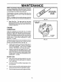
@
LUBRICA'I'ION
Check the crankcase oil level (See Fig. 18) before
starting the engine and after each five (5) hours of continuous use., Add S,,A_E.! 0W-30 motor oil or' equivalenL
Tighten fill cap/dipstick securely each time you checkthe
oil level. S..A.E. 5W-30 motor oil may be used to make
starting easier in areas where temperature is consistently 20 ° F_or lower_
FIG. 19
Change the oil after first two hours of operation and every
25 hours thereafter or at least once a year if the snow
thrower is not used fo_ 25 hours. (See Fig. 19)._
Position snow thrower so that the oil drain plug is
lowest point on the engine,. Remove oil drain plug
and oil fill cap/dipstick.
Drain oil into a suitable
container.. Oil wil! drain more freely when warm.
Replace oil drain plug and tighten securely_ Refill
crankcase with S..AE. 10W-30 motoroil (or equivalent). S.AE, 5W-30 motor oil may be used to make
starting easier in areas where temperature is consistently 20 ° Fo or lower+
PLUG
•
Make sure that the spark plug is tighte ned securely
into the engine and the spark plug wire is attached
to the spark plug.
•
If a torque wrench is available, torque plug to 18 to
23 foot pounds.
•
Clean the area around the spark plug base before
removal to prevent dirt from entering the engine.
•
Clean the spark plug and reset the gap periodically
_"
FIG, 18_
Auger Gear Box - The auger gear box has been
factory lubricated for life. Iffor some reason lubricant
should leak out, have augergear case checked by a
competent repairman.
SPARK
.._
FULLAND
ADDMARK
NOTE: For storage, the hex shaft and gears should be
wiped with 10W-30 motor oit to prevent rusting (See Fig..
t7)_
•
NOTE:OIL LEVEL
BETWEEN
__BE
16
S
CEAN
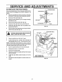
ADJUSTME
TS
i
CAUTION: ALWAYS DISCONNECT THE
SPARK PLUG WIRE AND TIE BACK AWAY
FROM THE PLUG BEFORE MAKING ANY
ADJUSTMENTS OR REPAIRS.
i
TO ADJUST
SKID MOUNTING
NUTS
i
SKIDS HEIGHT
This snow thrower is equipped with two height adjustment skids, located on the outside of the auger housing
These skids elevate the front of the snow thrower°
HEIGHT ADJUST
SKID
For normal hard surfaces, adjust the skids as follows:
e
Make sure the snow thrower is on a hard, level
surface and the weight transfer system lever is
released See page 12.
o
Place extra shear bolts supplied (found in parts
bag) under each end of the scraper bar near but not
under the skids
@
Loosen the skid mounting nuts (See Fig 20) and
push the skids down until they touch the ground.
Retighten the mounting nuts
/
i
TO ADJUST
CRANK
After considerable use, the metal scraper bar wilt have a
definite wear pattern. The scraperbar in conjunction with
the skids should always be adjusted to allow 1/8" between the scraper bar and the sidewalk or area to be
cleaned.
Position the snow thrower on a level surface
o
Loosen the carriage bolts and nuts securing the
scraper bar to the auger housing_
o
Adjust the scraper bar to the proper position
o
Tighten the carriage bolts and nuts, making su re that
the scraper bar is parallel with the working surface.
o
After extended operation, the scraper bar may be reversed, if the scraper bar must be replaced due to
wear, remove the carriage bolts and nuts and install
a new scraper bar
illl
/i
Jl
i
ii
ii
i
M_
ill
i
i
llllll///
//
i i
i
CHUTE
ASSEMBLY
If you cannot rotate the chute crank fully to the left and to
the right, you need to adjust the chute crank (See Fig 21 )
BAR
®
ill
CAUTION: BE CERTAIN TO MAINTAIN
PROPER GROUND CLEARANCE FOR
YOUR PARTICULAR
AREA TO BE
CLEARED. OBJECTS SUCH AS GRAVEL,
ROCKS OR OTHER DEBRIS, IF STRUCK
BY THE IMPELLER, MAY BE THROWN
WITH SUFFICIENT FORCE TO CAUSE
PERSONAL INJURY, PROPERTY DAMAGE OR DAMAGE TO THE SNOW
THROWER.
NOTE: tf the skids are at the maximum height, the weight
transfer system will not work
SCRAPER
ill
FIG. 20
For rocky or uneven surfaces, raise the front of the snow
thrower by moving the skids down This will help prevent
rocks and other debris from being picked up and thrown
by the auger°
TO ADJUST
/1//i
e
Loosen both 1/2" nuts on the crank adjusting rod
(using 3/4" wrenches)
o
Rotate the adjusting rod in or out to allow about t/8"
clearance between the notch in the flange and the
outer diameter of the worm
•
Once this clearance is set, tighten the nuts
NOTE: Be sure the crank does not touch the side of the
engine or the cover will be scratched
I
FLATWASHER 1
1/2 INCH
CRANK ADJUSTING
ROD
FIG_ 21
17
WORM
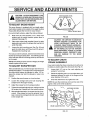
SERVICE AND
TO ADJusT
CABLES
US rMEN rs
THE CLU'TCH CONTROL
.................................................................................
............
:
....................
TRACTION
DRIVE __
!(_'_'\
LEVER
Periodic adjustment of the cables may be required due to
normal stretch and wear on the belts, To check for corr ect
adjustment, the control lever must be in the full forward
position, resting onthe plastic bumper.. The control cables
are correctly adjusted when the center of the "Z" Fitting is
in the center of the hole and ttlere is no droop in the cable
(See Fig. 22),.
•
_
/
/
..............................
•
Do the same forthe other lever cable
1
./1
[Ul
FIG. 22
Hold the square end of the threaded portion wittl
pliers and adjust the locknut in or out until the excess
slack is removed..
Pull the cable back through the spring and connect
the cable.,
LEVER
MUSTBEIN FULL
FORWARDPOSI']'ION (Just Contact-
i_[._.STICBUMPER
Push the cable through the spring (See Fig. 23) to
expose the threaded portion of the cable.
•
CONTROL
_
If adjustment is necessary:
•
'"
.......
_"_
TRACTION
AUGER
DRIVE
SPRING
NOTE: Whenever the track drive or auger belts are
adjusted or replaced, the cables wilt need to be adjusted,
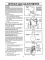
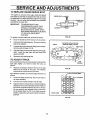
TO ADJ UST BELTS
END
Belts stretch during normal use., if you need to adjust
the belts due to wear or stretch, proceed as follows:
TRACK
DRIVE
BELT
LOCKNUT
(See Fig. 25)
FIG. 23
ii
i
i
HHIHIIIH I
II
JHJIll
.....
The track drive belt has constant spring pressure and
does not require adjustment. Check the clutch control
cable adjustment before replacing the bell
Replace the track drive belt if it is still slipping (see To
Replace Belts paragraph on page t9).,
AUGER
DRIVE BELT (See Fig. 25)
If your snow thrower will not discharge snow, check the
control cable adjustment If it is correct, then check the
condition of the auger drive belt. It may be loose or damaged. If it is damaged, replace it., See To Replace Bells
paragraph on page 19. If the auger drive belt is loose,
adjust as follows:
\
:
_IMPELLER
_
PULLEY
FIG. 24
•
Disconnect the spark plug wi{e.
•
Remove the belt cover,.
TRACK
•
Loosen the nut on the idler pulley (See Fig. 24) and
move the pulley toward the belt about 1t8".
;..:_ _
•
Tighten the nut..
DRIVE BELT
/
._',___/B
AUGER DRIVE BELT_
Press the augerdrivetever_ Checkthetensiononthe
belt (opposite idler pulley). The belt should deflect
about 1/2" with moderate pressure (See Fig,. 24)_
NOTE: You may have to move the idler pulley more than
once to obtain the correct tension.
Replace the belt cover.
•
Check the clutch control cable adjustment.
•
Reconnect the spark plug wire..
(Right Hand) __
_ TRACKPULLEY
DRIVE
AUGERpULLEyIDLER
__
BRAKE ASSEMBLY-""
IDLER PULLEY
FIG. 25
18
ELT GUIDE
Left Hand)
AUGER DRIVE
•
•
TRACK
DRIVE
. PULLEY
ADJUSTIVIE TS
..........................
SERVICE
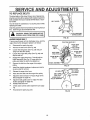
TO REPLACE
BELTS
The drive belts on this snow thrower are of special construction and should be replaced with original equipment
belts available from your nearest SEARS Store or Service Center°
BELT COVER
/
You will need the assistance of a second person while
replacing the belts,,
Drain the gasoline from the fuel tank by removing the fu el
line. Drain the gas and reinstall fuel line,,
ouTI
cAo,,o.:
DOORS, AWAY FROM FIRE OR FLAME
,,, ,,,
AUGER
,,
,
Ill,
1/4 X I12 INCH SELF
TAPPING SCREW
I
•
FIG, 26
DRIVE BELT
if your snow thrower will not discharge snow, and the
auger drive belt is damaged, replace it as follows:
•
Disconnect the spark plug wire°
e
Remove the belt cover (See Fig. 26)
®
Loosen the belt guides (See Fig, 28) and pull
away from the drive pulley°
Loosen the auger idler pulley (See Fig. 28) and
slip the belt out,
o
e
Engage the auger drive lever,, This will pull the
brake assembly (See Fig, 27) away from the
pulley and allow the belt to be slipped out.
e
Remove the belt from the auger drive engine
pulley°
e
Install the original equipment replacement belt in
reverse order of removal,
•
Release the auger drive lever,,
®
Place the drive belt onto the auger drive pulley.
•
Adjust the drive belt (see To _djust Auger Drive
Belt paragraph on page t8),,
o
Adjust the belt guides (see To Adjust The Belt
Guides paragraph on page 20).,
Reinstall the belt cover_
®
®
Check clutch control cable adjustment (see page
18),,
e
Reconnect the spark plug wire,
TRACTION
IMPELLER
DRIVE
BELT_
BELT GUIDE
(Right
AUGERIDLER
PULLEY
19
DRIVE BELT
TRACK DRIVE
PULLEY
GUIDE
(Left Hand)
AUGER DRIVE
PULLEY
TRACK DRIVE
IDLER PULLEY
SERVICE AND ADJUSTMEN TS
JL
.....
TRACK
.....
,,,,
H
i
m,
Jll,J
.....
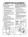
TO ADJUST THE FRICTION
DRIVE BELT
if the snow thrower will not move forward, you need to
check the track drive belt, the traction drive cable or the
friction wheel it the friction wheel is damaged, it will need
to be replaced_ See the To Replace Friction Wheel paragraph on page 21. If the friction wheel is not worn, check
the adjustment, as foItows:
If your snow thrower will not move forward, check the
track drive belt for wear. If the track drive belt needs to
be replaced, proceed as follows:
•
Disconnect the spark plug wire.
•
Remove the belt cover,
•
Loosen the left handbelt guide (See Fig 27) mounting screw and move the belt guide away from the
bell
WHEEL
•
Disconnect the spark plug wire_
•
Drain the gasoline from the_]as tank.
•
Stand snow thrower on the auger housing end.
•
Remove the bottom panel (See Fig, 29).
•
Pull the track drive idler pulley (See Fig. 27) back
and slip the belt past the idler pulley
Remove the belt from the engine pulley.
o
Position the shifter lever in first (1) gear.
•
Remove the belt between the two large pulleys
o
•
Install the new original equipment replacement belt
in reverse order of removal.
o
Adjust the left hand belt guide and tighten the
mounting screw (see To Adjust The Belt Guides
paragraph below).
Note the position of the friction wheel on the disc
drive plate The right side of the friction wheel should
be 3-3/8" fromthe left outer side of the discddve plate
(See Fig. 30)
•
o
Reinstall the belt cover.
O
Reconnect the spark ptug wire_
TO ADJUST
If adjustment is necessary:
THE BELT GUIDES
There are two belt guides on your snow thrower, a left and
right After you replace a track or auger drive belt, you
need to adjust one or both of the belt guides° Proceed as
follows for each belt:
•
Disconnect the spark plug wire.
•
Remove the belt cover (See Fig 26)
•
Engage the auger drive clutch lever,
•
Measure the distance between the belt guides and
the belt (See Fig 28)° The distance should be 3/32"
for each guide.
•
If adjustment is necessary, loosen the belt guide
mounting bolts. Move the belt guides to the correct
position Tighten the mounting bolts
o
Reinstall the belt cover.
o
Reconnect the spark plug wire
•
Loosen the jam nut "A" on the speed select rod Remove the ball joint from the shifter bracket Lengthen
or shorten the rod by turning the adaptor to obtain the
correct friction wheel position (See Fig. 31)
•
Reinstall the ball joint and tighten the jam nut.
•
Reinstall the bottom panel
FRICTION
WHEEL
DRIVE
PLATE
3-3/8
INCH
FIG. 30
SPEEDSELECTROD
- JAM NUT
IFTER
BRACKET
ADAPTOR,
REM
- _BI_.__I
LOOSEN BOLT,.._
|_.BOLT
BALL
LOOSEN
BOLT
PANEL
TRACK CONNECTING
I
t
ROD
FIG. 31
FIG. 29
2O
SERVICE AN
ADJUST
E TS
TO REPLACE FRICTION WHEEL
FRICTION WHEEL
If the snowthrower will not move forward, and the friction
wheel is worn or damaged, you need to replace it, as
follows:
e
Drain the gasoline from the fuel tank by removing
the fuel lineoDrain the fuel and reinstall the fuel line,.
e
Disconnect the spark plug wire,
®
Stand the snow thrower up on the auger housing
end (See Fig., 32).,
e
Remove the bottom panel (See Fig. 29).
e
Disconnect the right side track connecting rod,,
®
Rotate the right side track until it is parallel to the
ground (See Fig 33),,
•
Remove the three (3) fasteners securing the friction
wheel to the hub (See Fig. 32).
i
i
LOCKWASHER,
.T
NUT
HEX SHAFT
HUB
BOLT
illl
HEX SHAFT
CAUTION: DRAINGASOLINEOUTDOORS
AWAY FROM FIRE OR FLAME.
o
Move the shifter lever into first (1) gear.
•
Loosen the four No_, 10 keps nuts securing the
bearing plate (See Fig..33), Do not remove the nuts.,
HUB
NOo 10
NUTS
NOTE: Reassembly will be easier if you place a piece of
tape over each of the carriage bolt heads on the inside of
the motor mount before you remove the nuts,_
e
Move the speed select lever into sixth (6) gear.,
e
Remove the four No,, 10 keps nuts_
®
Remove the bearing plate,
®
Slide the hex shaft to the right until the friction wheel
can be removed.
O
Install the new friction wheel loosely on the hex
shaft,
O
PLATE
AUGER
HOUSING
(UNIT STANDING ON
AUGER HOUSING END)
Reinstall the removed parts in reverse order of removal
FIG. 33
21
........
IJlJ
i
],lll,ll,i,
...................
_ SERVICEAND
ADJUSTMENrS
TO REPLACE AUGER SHEAR BOLT
The augers are secured to the auger shaft with special
bolts (See Fig. 34) that are designed to break (to protect
the machine) if an object becomes lodged in the auger
housing° Use of a harder bolt wil! destroy the protection
provided by the shear bolt.
IMPORTANT:
TO iNSURE SAFETY AND
PERFORMANCE LEVELS, ONLY
ORIGINAL EQUIPMENT SHEAR
BOLTS SHOULD BE USED.. WHEN
REPLACING SHEAR BOLTS, BE SU RE
TO REPLACE SHEAR BOLT
SPACERS.
FIG. 34
To replace a broken shear bolt, proceed as follows:
•
Move the throttle to STOP and turn off all controls..
•
Disconnect the spark plug wire. Be sure alt moving
parts have stopped.
•
Lubricate the auger shaft zerk fitting (see the Maintenance section, pages !5-16).
o
Align the hole in the auger with the hole in the auger
shafL Install the new shear bolt and shear bolt
spacer provided.
•
Reconnect the spark plug wire.
TO ADJUST
TRACK
DISTANCE SHOULDNOT
BE
GREATER THAN 2INCHES
TRACK
(A)
If the snowthrower does not moveforward evenly and the
track slips slightly, you need to check the track, as
follows:
•
Measure the distance between the top of the side
plate and the inside of the track.. The distance
should not be more than two (2) inches..
FIG. 35
If the distance is greater, you need to adjust the track, as
follows:
o
Loosen the bolts (A) (See Fig.,35) on both sides of
the track assembly
o
Turn the cam washers equally on both sides°
O
Adjust the track to reduce slack, so that the distance
between the top of the side plate and the inside of
the track is not greater than two (2) inches. Be sure
the cam washers are adjusted evenly or the track
will be twisted (See Fig. 36). If the track becomes
twisted, readjust the cam washers to the correct adjustmenL
CAM
WASHER
...............................
_0UT
OF ADJUSTMENT
..........
_r
-t----CORREC
FRONT VIEW
FIG. 36
22
I
S RVICE AN
TO ADJUST
E TS
ADJUST
CARBURETOR
The carburetor (See Fig. 37) has been pre-set at the
factory and readjustment should not be necessary..
However, if the carburetor does need to be adjusted,
proceed as follows:
®
_IDLE
Close the high speed adjusting screw by hand..
®
Do not overtighteno
o
Then open it 1-1/4 to 1-1/2 turns°
®
Close the id)e adjusting screw by hand, Do not
overtighten.
o
Then open it 1-1/4 to 1-1/2 turns_
®
Start the engine and let it warm up,
o
Set the throttle control to FAST. Adjust the high
speed adjusting screw in until the engine speed or
sound alters° Adjust the screw out until the engine
speed sound alters. Note the difference between
the two limits and set the screw in the middle of the
ADJUSTING
_:j-
SCREW
(Close finger tight only)
(Close finger tight only)
e
®
®
i i Hl=,,Hll
,l= ,
FIG. 37
TO ADJUST:
e
Clean the spark plug by carefully scraping electrodes (do not sand blast or use a wire brush)_
o
Be sure the spark plug is clean and free of foreign
matedaL Check electrodes gap (See Fig. 38) with a
wire feeler gauge and reset the gap to 030 inch if
necessary_
range..
Set the throttle control to SLOW,. Adjust the idle
adjusting screw in until the engine speed drops,
then adjust the screw out until the engine speed
drops. Note the difference between the two limits
and set the screw in the middle of the range..
If the engine tends to stall under load or not accelerate from low speed to high speed properly, adjust
the high speed screw out in 1/8 turn increments until
the problem is resolved°
.030 GAP
Let the engine run undisturbed for 30 seconds
between each setting to allow the engine to react to
the previous adjustments.
IMPORTANT:
NEVER TAMPER WITH THE ENGINE
GOVERNOR, WHlCH IS FACTORY
SET FOR PROPER ENGINE SPEED.
OVERSPEEDING THE ENGINE
ABOVE THE FACTORY HIGH SPEED
SETTING CAN BE DANGEROUS.
IF YOU THINK THE ENGINE
GOVERNED HIGH SPEED NEEDS
ADJUSTING, CONTACT YOU R
NEAREST SEARS SERVICE CENTER,
WHICH HAS THE PROPER
EQUIPMENT AND EXPERIENCE TO
MAKE ANY NECESSARY
ADJUSTMENTS,.
FIG. 38
TO REPLACE:
TO ADJUST OR REPLACE
THE SPARK PLUG
If you have difficulty starting you r snowthrower, you may
need to adjust or replace the spark plug. Follow the
instructions below.
Replace the spark plug it electrodes are pitted or burned
or if the porcelain is cracked
23
e
If you need a new spark plug, use only the proper
replacement spark plug.
e
Set the gap to _030 (See Fig 38).
o
Before installing the spark plug, coat its threads
lightly with graphite grease to insure easy removal
•
Tighten the plug firmly into the engine,
•
If a torque wrench is available, to rque the plug to 18
to 23 ft - Ibs
ii ii.
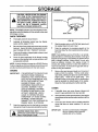
E
......................
CAUT'iON:
NEVE"STORE
THEENGINE
WITH FUEL IN THE TANK INDOORS OR
IN AN ENCLOSED, POORLY VENTILATED
AREAWHERE FUEL FUMES MAY REACH
AN OPEN FLAME, SPARK OR PILOT
LIGHT AS ON A FURNACE,. WATER
ttEATER, CLOTHES DRYER, ETC,.
NOTE: Immediately prepare your snow thrower for storage at the end of the season or'if the unit will not be used
for 30 days or more,.
BOWL DRAIN
SNOW THROWER
•
Thoroughly clean the snow thrower'.
•
Lubricate all lubrication points (see the Maintenance section, pages 15 -16).
•
FIG. 39
Be sure that all nuts, bolts and screws are securely
fastened. Inspect all visible moving parts for damage, breakage and wear° Replace if necessary.
•
Touch up all rusted or chipped paint surfaces; sand
lightlybefore painting,
•
•
Start the engine and run at SLOW (idle) speed until
the engine stops from lack of fueL
•
Drain the carburetor by pressing upward on the
bowl drain (See Fig_39), located below the carburetor cover_
NOTE: Fuel stabilizer (such as STA-BIL) is an acceptable alternative in minimizing the formation of fuel gum
deposits dudng storage Add stabilizer to gasoline in fuel
tank or storage container, Always follow the mix ratio
found on stabilizer container_ Run engine at least 10
minutes after adding stabilizer to allow the stabilizer' to
reach the carburetor,.Do not drain the gas tank and carburetor if using fuel stabilizer_
Cover the bare metal parts of the blower housing
auger and the impeller with r_Jstpreventative, such
as sprayable lubricant.
NOTE: A yearly checkup o r tuneup by a S EARS Service
Center is a good way to insure that your snow thrower will
provide maximum performance for the next season.,
ENGINE
IMPORTANT:
Remove the spark plug and squirt one (1) ounce of
engine oil into the cylinder. Pult the recoil starter
rope slowly, allowing the piston to coat the internal
engine parts.. Install an old spark plug. This
prevents fouling a new plug with the preservative
used to lubricate the internal parts of the engine_
Close the choke and plug the muffler opening°
ITIS IMPORTANTTO PREVENTGUM
DEPOSITS FROM FORMING IN
ESSENTIAL FUEL SYSTEM PARTS
SUCH AS THE CARBURETOR, FUEL
FILTER, FUEL HOSE OR TANK
DURING STORAGE.. ALSO,
EXPERIENCE INDICATES THAT
ALCOHOL BLENDED FUELS
(CALLED GASOHOL OR USING
ETHANOL OR METHANOL) CAN
ATTRACT MOISTURE WHICH
LEADS TO SEPARATION AND
FORMATION OF ACIDS DURING
STORAGE. ACIDIC GAS CAN
DAMAGE THE FUEL SYSTEM OFAN
ENGINE WHILE IN STORAGE.
OTHER
Drain the gasoline from the fuel tank by removing
the fuel line. Drain the fuel and reinstall the fuel lined
•
If possibJe, store your snow thrower indoors and
cover it to give protection from dust and dirt.
•
If the machine mustbe storedoutdoors, block upthe
snow thrower to be sure the entire machine isoff the
ground.
•
Cover the snow thrower with a suitable protective
cover that does not retain moisture, Do not use
plastic.,
IMPORTANT:
Ii
"'i...... _ ............
C_'_T'ioN:
,
DRAIN FUEL iNTO .........
i
APPROVED
CONTAINER
OUTDOOBS,
I
! AWAY FROM OPEN FLAME.
............. i
24
NEVER COVER SNOW THROWER
WHILE ENGINE AND EXHAUST
AREAS ARE STILL WARM
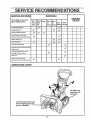
SERVICE
SERVICE
COIVl
RECORDS
Fill in dates as you complete regular service
NDATiO
S
SCHEDULE
ii
SERVICE
DATES
i
After
Before Often
First 2 Each
hours Use
Every Every
10
25
Each
Before
Hours Hours Season Storage
i III,ILILll
Check Engine Oil Leve!
.....
.....
J
....=
,
i_
Ii
Change Engine Oil
33gfiten All Sc'rews and Nuts
...................
v"
....
Check Traction Cfutch Cable
.............
i
== =.
Adjustment (See Cable AdjusLrnent)
Replace Sp_
Plug
A_djustDrive" Belts=
Lubricate All Pivot Points
Lubricate Auger Shaft (See Shear Bolt
Replacement)
"=Lubricatesprockets
and Chains
Sparingly (Track Assembly)
Drain Fuel
Check
AugerCiuto.Cabie
Adjustment
ii
(See Cable Adjustment)
LUBRICATION
CHART
Oil chains and
sprockets with
10W-30 oil.
Lubricate Auger Shaft. Coat
with a clinging type grease
such as lubriplate.
25
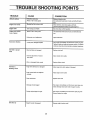
TROUBLE SHOOTING POINTS
TROUBLE
CAUSE
Difficult'starting
CORRECTION
Defective spark plug
Replace defective plug.
Water or dirt in fuel system
Use carburetor bow] drain to flush and refill with fresh
fuel.
Engine tuns erratic
iii
' 'B'locked
fu':i'"ii'.'e
oriowonfuel
,,,,,,,,, ,
Clean fuel line; check fuel supply; add fresh
gasoline (Gasolinetoil
..........
mixture if 2 cycle #ngine.),
Engine stalls
Unit running on CHOKE
Set choke lever to RUN positio_
Engine runs erratic;
Water or dirt in fuel system
Use carburetor bowl drainto flush and refill withfresh
fuel
Carburetor
Adjust carburetor,
Loss of power
Excessive
vibration
out of adjustment
Loose parts;damaged impeller
Step engine immediately and discont_ect spark plug wire
Tighten all bolts and make all necessary repairs If vibration
continues, have the unit serviced by a competent repairman
Unit falls to propel
Drive belt loose or damaged
Replace drive belt.
Incorrect adjustment of traction
drive cable
Adjust traction drive cable.
Worn or damaged friction wheel
Replace friction wheel.
Auger drive belt loose or damaged
Adjust auger drive belt; replace if damaged
Auger control cable not adjusted
Adjust auger control cable..
itself
Unit fails to
discharge snow
correctly
Shear boil broken
Replace shear bolt
Discharge chute clogged
Stop engine immediately
and disconnect
spark plug wire..
Clean discharge chute and inside of auger housing
Foreign object lodged in auger
Stop engine immediately and disconnect
Remove object from auger
Unit rides up
Weight transfer disengaged
Engage weight transfer pedal
26
spark plug wire.
I
NOTES
27
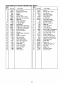
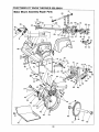
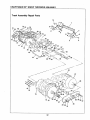
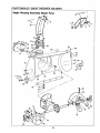
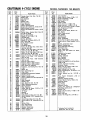
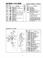
CRAFTSMAN
23" SNOW THROWER
Handle Assembly
536.884811
39
Repair Parts
1
60
3
1
3
59
-40
62
_--4
41
28
57
33
_132
.10
11
2930
63
18
52
17
22
64
49
48
5O
7
16
17
17
19
45 51,
47 46
21
17
16
43
24 26
18
28
46
47
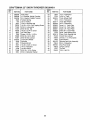
CRAFTSMAN
REF.
NO,
PART NO.
1
2
3
4
5
6
7
8
9
t0
11
12
13
14
15
16
17
18
19
2O
21
22
23
24
25
26
27
28
29
30
31
32
3535
309344
3538
4049
308012
70990
309059
308037
6300
71059
71034
306523
310421
308901
310391
71042
71060
50782
6352
50786
71072
71O38
1668
1449
73801
73812
t579
7288
71062
71044
7289
71045
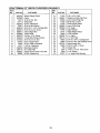
23" SNOW THROWER
536.884811
PART NAME
REF.
NO.
PART NO.
33
34
35
36
3'7
38
39
40
41
42
43
44
45
46
47
48
49
5O
5!
52
53
54
55
56
57
58
59
60
61
62
63
64
71457
70984
308011
1672
1673
71035
304872
307399
17
148
71082
104
7O55
7058
7059
70993
7052
1162
71037
71071
71007
3903
3902
308146
308145
50780
307920
307918
309310
309312
71046
307148
PART NAME
,,
5/16 InoCap Nut
Adapter, Boot to Handle
Pivot Pin
Bumper
Upper Handle
5/16-18 x 1-3/4 Inr Screw
Bracket, Chute Rotate Stop
Shift Lever
Decal, Gear Selector
1/4 In, Lockwasher
1/4..20 Hex Nut
Control Panel
Support Control Panel Ass'y
Taptite Screw, 10-24 x 5/8 lno
1/4-20 x 2 InoCarriage Bolt
5/16-24 Hex Nut
5/16 In. Lockwasher
Ball Joint
Adapter, Speed Control Rod
Spring
t3/32 In., Flatwasher
5/16-18 Hex Nut
Speed Control Rod
Lever, Speed Control
5/32 x 7/8 In..Spring Pin
1/2 in.. Flatwasher
Clutch Cabie
3/8-16 x 3 In. Screw
3/8 In. Lockwasher
3/8-16 Hex Nut
Plastic Stop
3/8-16 Jam Nut
29
,
,, .....
Eye Bolt
5/16-18 x 3/4 In Screw
Lower Handle
Drive Clutch Spring
Auger Clutch Spring
1/4-20 Locknut
Retainer Ring
Chute Crank Handle
Chut_e:Crank Assembly
Eye Bolt Grommet
3132 x 1 In. Cotter Pin
Plastic Cap
Chute Control Rod
1/2-20 Jam Nut
I12 InoLockwasher
5/16-18 x 3/4 In. Carriage Bolt
L.H., Chute Rotate Bracket
R..H..Chute Rotate Bracket
5/t6-18 Hex Nut
'11/32 In Ffatwasher
3/8-16 x 2 In. Hex Hd Bolt
Auger Drive Control Decal
Traction Drive Control Decal
Clutch Spring Boot
Eyebo_t Boot
Plastic Knob
Traction Drive Lever, L H
Auger Drive Lever, R..H.
Plug, Nylon
Washer, Flat
3/8" Nylon Locknut
Owner's Manual
CRAFTSMAN
23" SNOW THROWER
Motor Mount Assembly
536.884811
Repair Parts
49
51
53
91
65
!8
18
54 52
58
60
5
62
57
6,
37
55
70
68
_
67
©
69
23
9i
72
87 74
90
7 73
13
8 29
___
31
32
24
20
60 77
5O
78\
33
31
8O
84
81
85
83
42
44
26
/
25
45
87
47
46
48
12
33
88
14
71
15
3O
89
88
CRAFTSMAN
REF,
NO,
i
2
3
4
5
6
7
8
9
10
11
12
13
14
15
16
17
'18
19
20
21
22
23
24
25
26
27
28
29
30
3!
32
33
34
35
36
37
38
39
40
41
42
43
44
45
46
47
48
49
23" SNOW THROWER
536.884811
REF. t
PARTNO.
308646
307696
308054
70988
71060
85494
71074
73801
53703
85492
71067
70978
70982
62'15
308009
50795
7287
6106
7O985
73795
53793
53794
71391
53704
590
71010
71072
73787
55026
55027
71071
71393
577399
53788
20579
30289
6103
577269
53714
50677
71063
71015
50793
145!
443
301545
5939
3526
85495
No. I
PART NAME
Motor Mount Frame
Belt Cover
Tecumseh Engine, 5 HP, 4 Cy
5/16-18 x1-1/4 In. Bolt
5/16 tn. Lockwasher
Clutch Cable Lever
1/2 In.. Flatwasher
5/32 x 7/8 In. Spring Pin
Bushing, Plastic
Clutch Auger Lever Assembly
1/4 In. Flatwasher
1/4-20 x I/2 In. Self Tapping Scr
5/16-18 x 1/2" Self Tapping Scre
48 Tooth Gear
Bottom Cover
I
5O
51
52
53
54
55
56
73812
71111
71461
85504
6105
6107
72531
53833
53832
71086
73811
85501
53831
53830
t't87'1
71059
71034
3080O5
71360
71035
51438
73839
85499
53816
71079
73817
53807
7091
7286
53818
,
53820
53821
53819
i
I
73823
1
73822
1
71081
!
70970
73826
53836
5923
I
71045
71062
48275
t
t 307697
1 310169
f 308900
I 308903
I
71005
58
59
60
61
62
63
64
65
66
3/4 In..Hypro Key
Roller Bearing
1/2 In. Flatwasher
5/16-18 x 3/4 In. Bolt
5/16 x 1-3/8 In. Flatwasher
Idler Traction Lever
Spacer, Sleeve
5/16-t8 Hex Locknut
68
70
71
73
74
75
Idler Traction Drive Spring
3/8-16 Hex ,Jam Nut
3/8-16 x 1-1/2 In Bolt
318 In.. Flatwasher
Belt Retainer Washer
L.H BeR Guide
R.H. Belt Guide
11/32 In. Flatwasher
5/16-24 x 1 In. Bolt
5/I6-18 x 1/2 In. Set Screw
Engine Pulley
Key, Woodruff # 5
1/2 In. Wave Washer
Outer Bearing Retainer
Engine Pulley Spacer
Engine Drive Pulley
Flatwasher
3/8 In Lockwasher
3/8-24 x 1 InoBolt
1-7/8 In, Idler Pulley
Shaft & Levers Assembly
Auger Brake Spring
5 In. Impeller Pulley
Special Traction Drive Belt
Special Auger Drive Belt
Shift Control Shaft
78
79
81
82
83
84
85
°°1
87
88
89
91
92
93
94
95
96
97
31
PART NO.
',
PART NAME
1/2 In Flatwasher
3/8-16 Hex Locknut
#10_24 Keps Nut
Bearing Assembly
Inner Bearing Retainer
Ball Bearing
10-24 x 3/8 In_Carriage Bolt
8 Tooth _inion Gear
Hex Disc Friction Wheel Shaft
1/8 x 3/4 In Spring Pin
1/4 In..Snap Ring
Trunion Bearing
Friction Wheel Hub
Friction Wheel
1/4-20 x 5/8 In..Bolt
1/4 In..Split Lockwasher
1/4-20 Hex Nut
Pivot Bracket
1/4-20 x 1-3/4 in Bolt
1/4-20 Hex Locknut
5/16 In..Spacer, Sleeve
1/4-20 x 2-1/4 In. Bolt
Traction Shaft Assembfy
t/2 In. Spacer, Sleeve
1/8 x 1 In_Cotter Pin
1/2 inn Push-on Nut
Friction Wheel Disc
Traction Hex Shaft
Thrust Bearing
Return Spring
Clutch Spring
Clutch Rod
Traction Spring Bracket
1/8 x 1-3/8 In_ Spring Pin
1/8 x 1/2 in. Spring Pin
3/32 x 3/4 In. Cotter Pin
1/4-20 x 1-1/4 In Bolt
I/4-20 Hex Locknut
Shaft Hex Bearing
Track Axle Shaft
Nut, 3/8-16
Washer, Splitlock
Washer, Flat 3/4 In
,Fender
Screw, 1/4-20 x 3/8 In
Screw, 14-10 x 3/4 in..
Nut, 14-10 "J" Type
Screw, 3/8-16 x 1 In
CRAFTSMAN
23" SNOW THROWER
Track Assembly
536.884811
Repair Parts
14
21
21 22
36
32
37
25
19
15
11
17
22
37
15
26
20
3O
÷
42
43
33
29 26 25
24
27
\
18
19
15
35 19
16 15
26 19
36 37
2O
31
40
23
21
32
CRAFTSMAN
NO.
1
2
3
4
5
6
7
8
9
10
11
12
113
14
15
16
i
17
18
19
20
! 21
22
PART NO.
308048
308038
308039
6025
518
6001
70978
71060
71037
73839
6215
7285
70985
71391
301818
5930
59'17
5947
71067
6108
71348
5951
23" SNOW THROWER
536.884811
PART NAME
Foot Pedal
L,H. Bracket, Weight Transfer
R..H, Bracket, Weight Transfer
Tension Spring
1!2 In,,Pal Nut
7/16 In.,Shoulder Bolt
1/4-20 x 1/2 In Serf Tapping Screw
5/! 6 In, Lock'washer
5/16_18 Hex Nut
1/4-20 x 2-1/4 In,,Screw
48 Tooth Gear
Screw, 1/4-20 x 1-1/2 In_
5/16-18 x 3/4 in., Bolt
5/16-18 Hex Locknut
Track Drive Wheel
Sprocket
Chain #420-50
1/4-28 x 3-3/4 In, Screw
1/4 In. Flatwasher
1/4-28 Locknut
5/16-18 x t/2 In. Screw
5/16 In,.BeIleville Washer
33
REF.
NO.
PART NO,
PART NAME
23
24
25
26
27
28
29
3O
31
32
33
34
35
36
37
38
39
40
41
42
43
5950
9724
302024
7074
301817
305299
308883
308882
308061
308056
9756
301819
71O35
70969
6403
304133
73840
308784
73826
9727
20465
1/2 In. Flatwasher
4-3/4 In_Track
Track Wheel Shaft
1/2 In, Flatwasher
Track Idler Wheel
3/4 In, Flatwasher
Inner L,H, Track Plate
Inner RH. Track Plate
Outer LIH'. Track Plate
Outer RoHoTrack Plate
Inner Track Bearing Hub
Outer Track Bearing Hub
1/4-20 Hex Locknut
1/4_20 x I in. HHC Screw
Cam Washer
Sprocket and Hub Assembly
3/4 In Flatwasher
Trac Plus Decal
1/4-20 Locknut
Tie Rod
1/8 In, Hair Pin
CRAFTSMAN
23" SNOW THROWER
Auger Housing Assembly
536.884811
Re )air Parts
,o f il
32
29
18
\
36
)
33
3 15 16
35
38
38
3O
31
27
4O
34
28
CRAFTSMAN
REFo
NO.
1
2
3
4
5
6
7
8
9
t0
11
12
13
14
15
16
17
18
19
20
PART NO. i
308768
307665
71037
57171
302680
71391
302843
302634
308931
307698
302678
302635
577400
53759
71060
71071
308059
308119
302922
20556
23" SNOW THROWER
536.884811
PART NAME
Striped Danger Decal
Chute
5/16_18 Hex Nut
Wing Knob
5/16 In. Flatwasher
5/16-18 Hex Locknut
5116-18 x 1-1/4 In. Carriage Bolt
5116-18 x 3/4 In. Screw
Chute Hinge Wire
Lower Chute
•1/4-20 x 112 In. Screw
1/4-20 Wide Flange Locknut
5/16-18 x 3/4 In. Bolt
6.5 In. Auger Pulley
5/16 inn Split Lockwasher
11/32 In, Flatwasher
Bearing & Retainer
R,H Side Plate
Danger Decal, Read From Side
3/16 In_ Square Key
35
REF.
NO.
PART NO.
21
22
23
24
25
26
27
28
29
30
31
32
33
34
35
36
37
38
39
40
71032
309057
85480
71058
70142
308839
308053
73755
70141
73826
308052
308118
70993
70984
307912
7O983
736
9524
3943
53757
PART NAME
8-32 x 1/2 Ino Bolt
Retainer w/Stop Clip,Chute
Lower Chute Ring Clip
#8-32 Hex Locknut
Chute Danger Decal
Lower Chute Ring
R..HoAuger
Auger Washer
Auger Danger Decal
1/4-20 Locknut
L,H. Auger
L,H. Side Plate
5/16-18 x 3/4 ln_ Carriage Bo_t
5/16-18 x 3/4" Self Tapping Screw
Height Adjust Skid
5/16-t8 x 5/8 In, Screw
Scraper Bar
t/4-20 x 1-3/4 In HHC Screw
1/4 In. Spacer
1 In.,Auger Shaft Bearing
CRAFTSMAN
GEAR
23" SNOW THROWER
BOX REPAIR
536.884811
PARTS
10
7
11
12
13
1
15 16
8
6
17
19
18
20
21
2O
19
22
/
5
23
24
6
PAR]" NO.
1
i
tl
71393
308051
73905
3956
71100
1065
53737
10905
53735
53734
53733
50795
REF,
NO,
PART NAME
5/16-24 X I In,. Bolt
13
14
15
!6
17
18
!9
2O
21
22
23
24
impeller'& Shaft Assembly
Woodruff Key #9t
Auger Shaft, 23 Ino
5/16-24 Flange Locknut
Oil Seal
Quad Ring
Flange Bearing
7/8 In,, Flatwasher
7/8 In, Roller Bearing
7/8 In_Flatwasher
3/4 in_ Key
36
PART NO.
53732
50683
50688
5373 t
895
53749
53743
53748
53730
897
896
912
PART NAME
1-3/4 In,. Worm Gear
3/4 In. Flatwasher
Retaining Ring
Sleeve Bearing
L_H. Gear Box Housing
1/4 x 18 Pipe Plug
Auger Gear Box Bearing
1 In, Flatwasher
Worm Gear'
Gear Box Gasket
R H. Gear Box Housing
5/16-24 x 1-1/2 In. Bolt
REWIND
STARTER
12
NO. 590646
Refo
No.
!
13
_2
37
1
2
3
4
5
6
7
8
9
10
11
12
Part
No.
Part Name
59O646 iStarter, Rewind
590599A iPin, Spring _(}_cLNo. 4)
590600 Washer
590615 Retainer
590601 iWasher
590598 ISpring, Brake
590616 Dog, Starter
590617 Spring, Dog
590645 Pulley
590619 Spring, Rewind
590620 Cover, Spring
590647 Housing Assyo, Starter
590451A Rope, Starter (Length 69" E_5/32'
13
590574
diaJ
Handle, Mitten Grip (Not include,
with starter)
CRAFTSMAN
4-CYCLEENGINE
MODEL
NUMBER:
143.804072
IIIII
II
218
II IIIII
,,,...-"*'
221
. J'e.,...._ _'-,-..
219
L
48
I
18
"
I85
..f202
228
149
"
i
I
I
I
"_'-186
203 30_i
MODELand SERIAL
NUMBERSHERE
11
102 ___31
9
>
290C
38
i
_
]1
CRAFTSMAN
4=CYCLE
ENGINE
Ref.
No.
Part
No.
Part Name
MODEL
Part
No.
I Ref.
I No.
NUMBER:
143.804072
PartName
r"_'
"
1
5
6
7
8
9.
10
11
12
20
2t
33674B
34171
3O969
326O0
28277
31334
31510
31335
65O548
_33342
650_1
22
t33838A
23
24
25
28
31
32
35
45
46
47
31342
650549
610973
31426
165O139
130322
35440
26727
34740
34535
47
34536
47
34537
48
48
335628
33563B
48
335648
49
49
49
50
51
33567
33568
33569
20381
32875
52
53
54
55
56
57
58
59
60
70
71
72
73
74
75
76
77
78
79
32654
32610A
27241
33696
32323
"27677A
34678
27897
30318
35479
30591
30574
30568A
29193
650488
35554
35499
35556
35539
29313C
29315C
84 i
84
32644A
32645A
Cylinder Assy. (lncl, Nos, 7 8 46)
Nipple, Pipe
Cap, Oil drain
Seal, Oil
Washer, Flat
Rod, Governor
Lever, Governor
Clamp, Governor lever
Screw, Hex washer hdo, 8-32 x 5/t6
Baffle, Blower housing
Screw, Hex washer hd. Durlok, I/4-20
x 5/8
Control Assy., Bracket (IncL Nos, 23
thru 25, 31 _ 32)
Spring, Compression
Screw, FiL hd, 5-40 x 7/16
Terminal Assy.
Spring, Extension
Screw, FiL hd. Seres, 8-32 x 1/2
Nut, Lock, 8-32
Knob, Speed control
Pin, Dowel
Crankshaft Assy.
Piston, Pin _ Ring Assy. (Std_} (tncl.
Nos_ 48, 49 5" 50)
Piston, Pin Ef Ring Assy, (,010 oversize) (Inclo Nos. 48, 49 Et 50)
Piston, Pin Et Ring Assy. (,020 oversize) (fncl. NOSo48, 49 _ 50)
Piston E_Pin Assy.. (Stdo) (IncL No. 50)
Piston E_ Pin Assy. (Ot0 oversize)
(Incl. No. 50)
Piston _ Pin Assy.. (020 oversize)
(incl_ No, 50)
Ring Set, Piston (Std.)
Ring Set, Piston (.O10 oversize)
Ring Set, Piston L020 oversize)
Ring, Piston pin retaining
Rod Assy.., Connecting (|ncL Nos, 52
53)
Dipper, Oil
Bolt, Connecting rod
Lifter, Valve
Camshaft (Compression Release)
Washer, Thrust
Gasket, Cylinder cover
Cover, Cylinder (inct, Nos° 59, 60 _ 72)
Seal, Oil
Seal, Camshaft
Washer, F_at
Gear, Governor (Incl, No. 70)
Shaft, Mechanical governor
Spool, Governor
Ring, Retaining
Screw, Hex hd, Seres, 1/4-20 x 1.1/4
Tube Assy., Oil fill
"O" Ring
Dipstick
Clip, Oil fill
Valve, Exhaust (Std.) (Incl. Noo 86)
Va}ve, Exhaust (1/32" oversize) (IncL
No. 86)
Valve, Intake (Std.) (lncL No., 86)
Vafve, Intake (!/32" oversize) (tncL No
i
91
I
93
95
i
96
i
97
98
99
100
101
102
140
141
142
143
144
145
146
147
148
149
35350
650128
29752
*26756
33691
"33673A
6201
650870
650664
32698
34583
28820
34582
35438
35593
610973
35285
35072
650257
650735
150
160
161
162
163
164
165
181
182
183
184
185
186
187
189
191
192
t93
194
195
196
197
198
201
202
203
204
205
210
211
216
217
218
i
J
J
Tube, Breather
Screw, Hex hd. Seres, 10-24 x 1/2
Nut _ Lockwasher, 1/4-28
Gasket, Carburetor
Pipe, Intake
Gasket, intake
Screw, Hex hd°, !/4-28 x 7/8
Screw, Hex hd., t/4-28 x 1-tl/16
Screw, Fil. hd. Semso I/4-20 x 1-19/32
Link, Governor._tothrottle
Bracket, Chok_-"
Screw, Fil, hd,. Sems, 10_32x t/2
Rod, Choke
Knob, Choke control
Key, Ignition
Terminal Assy.
Wire, Ground
Cover, Carburetor
Screw, Pan hdo Semso 8-32x 5/16
Screw, Hex hd., Seres, rapt(re, t0-24 x
3/8
33333
Bracket, Carburetor cover
3408O Spacer, Flywheel key
650872
Stud, Solid state mounting
34443A Solid State Assy.,
610118
Cover, Spark plug
650814
Screw, Torx hex washer hd. Seres,
10-24 x I
611O81
Flywheel (w/ring gear)
610961
Key, Flywheel
650815
Washer, Belleville
65O863
Nut, Flywheel
35557
Wire, Ground
34212
Bracket, Hold down
30200
Screw, Hex washer hd. self-tap Sems,
10-24 x 9/16
34126
Bracket, Grommet mounting
28545
Grommet, Plastic
650760
Screw, Pan hd. taptite, 8-32 x 3/8
"33554A Gasket, Cylinder head
33016A Head, Cylinder (lncL No.. 218)
6021A Screw, Hex flange hd., 5/16-18 x 1-!/2
650691
Washer, Fiat
650818
Screw, Special hex hd., 5/16-18 x
1-1/2
33636
Plug, Spark (Champion J-8C or
equivalent)
29745
Extension, Blower housing
650128
Screw, Hex hd. Seres, 10-24 x 1/2
35656
Housing, Blower
570682
Primer Assy,.
32180C Line, Primer
33341
Extension, Baffle
650701
Screw, Hex washer hd. shakeproof
self-drilling, 8-18 x 7/16
650168
Washer, Flat
29212
Screw, Hex hd_ Seres, 1/4-28 x 7/16
33344
Baffle, Heat
28371B
Plate, Fuel tank
650694A Screw, Hex flange hd, 5/16-18 x 2
86)
85
86
87
88
89
9O
31672
31673
27666
31410
"27234A
34146
Spring, Valve
Cap, Valve spring
Body, Valve cover
Element, Valve body
Gasket, Valve cover
Cover. Breather
*Indicates Parts Included in
Gasket Set, ReL No. 305.
39
CRAFTSMAN
4-CYCLE
ENGINE
Part
No.
ReL
No.
)
"33670A
33697A
650327
8345
30O63
231
232
35584
35355
650665
) 24_9
i 251
)
)
2646O
30705
34694
65O884
65O168
590574
35392
34346
) 256
1270
_ 274
!276
276
277
290A
CARBURETOR
No.
Bracket, Fuel tank mounting
Washer, Flat
Screw, Hex hd. w/bellevilie washer,
1/4-20 x 11/16
Gasket, Exhaust
Muffler
Screw, Fil. hd_ Seres, 1/4-20 x 2-i/2
Washer, Flat
Screw, Hex washer hd. Seres, 1/4-20
x t/2
Tank Assy., Fuet (IncloNos_250 _ 253)
Cap, Fuel tank
Screw, Hex washer hd. self-tap Seres,
1/4-15 x 7/8
Clamp, Fuel line
Line, Fuel
Cup, Starter
Screw, Hex washer hd.o 8-32 x 1/2
Washer, Flat
Handle, Starter
Plug, Starter
Decal, Instruction
)
)
229
23o
NO.
290B
290C
290D
290F
300
301
303
No.
305
RPM Settings: _:
Low Speed: 21(_), High Speed: 3700.
"Indicates Parts Included in
Gasket Set, Ref. No, 305.
tin original production the speed control assembly is riveted to the blower
housing baffle. Replacement speed
control assembly includes screws and
nuts for mounting, Replacement baffle
has threaded hoies_
632107A
......,
,/
I
[
4... ,...,
_..-_
i31
24
11
/:=
L
).
Part Name
Decal, Primer
Decal, Choke
Decal, Warning
Decal, Instruction
Carburetor (IncL No. 96)
Starter, Rewind
Electric Starter Kit 143o88933 (Optional) Sold as accessory
33683B Gasket Set (Inctoitems marked *)
No.
15
143.80407_
34144
35282
34414
35312
632107A
590646
Ref.
•
NUMBER:
Part
Part Name
34182
65O675
65O805
219
22O
MODEL
15
I!
"m'b
:)
14
_P'_126
(
17
!
I
J !
18
12
23 _o
31----o
--22
30 _{_
"""
13
32
4O
Pa1't
No.
632107A
531615
631767
631036
65O5O6
63O766
650417
632108
630735
631815
"630748
"631027
*631021
Part Name
Carburetor
1
Shaft _ Lever Assy,, Throttle
2
Spring, Throttle return
3
Shutter, Throttle
4
Screw, 4-40 x 3/16
5
Spring, Idle regulating screw
6
Screw, Idle regulating
7
Shaft _ Lever Assy, Choke
8
Spring, Choke stop
9
Shutter, Choke
10
Plug, Welch
1t
Plug, Welch
t2
Inlet Needle, Seat et Clip Assy.
Incl. No. 13)
13 631022 Clip, inlet needle
t4
632019 F(oat, Carburetor
t5 *631024 Shaft, Float
16 631951 Bowl, Float (tncL Nos. 17 8- 18}
17
27136A Drain Assyo, Bowl (lncl No, 18)
18 "27554 Gasket, Bowl drain
21
27110 Gasket, Bowl_to-body
22
"31839 Adjustment Screw Assy., Main
(Incl_ Nos_ 21, 23, 30 e 31)
23 *630740
"O" Ring, Adjustment screw
24 "631838
Screw, Idle adjustment
25 *631028
Gasket, Bowl-to-body
26
631807 Fitting, Fuel inlet
3O
630738
Spring, Main adjustment screw
31
630739 Washer, Flat
32
31840 Repair Kit {Inclo items marked ")
I
NOTES
41
CRnFrIMIIN®
OWNER'S
MANUAL
MODEL NO.
536.884811
5 HORSEPOWER
23" DUAL STAGE
TRAC-PLUS
OPTIONALELECTRIC
START
SNOW THROWER
Each SNOW THROWER
has its own MODEL
NUMBER found on the motor mount flame.
Each ENGINE has its own MODEL
found on the BLOWER HOUSING°
NUMBER
Always mention these MODEL NUMBERS when
requesting service or Repair Parts for your SNOW
THROWER.
All parts listed herein may be ordered through
any Sears Service Center/Department
and most
Sears Stores,
WHEN ORDERING
REPAIR
PARTS, ALWAYS
GIVE THE FOLLOWING INFORMATION:
HOW TO ORDER
REPAIR PARTS
* PRODUCT - "SNOW THROWER"
* MODEL NUMBER - 536.884811
* ENGINE MODEL NUMBER 143.804072
* PART NUMBER
* PART DESCRIPTION
"Your Sears merchandise has added value when you
consider that Sears has service units nationwide staffed
with Sears trained technicians ,,.Professional technicians
specifically trained on Sears Products, having the parts,
tools and equipment to insure that we meet our pledge
to you._we service what we sell,"
......
i
ill
lU
uJll
ill
i
i i
SEARS, ROEBUCK AND CO., Chicago IL. 60684
307148 09116!89
Printed in U.S.Ao