1
UEll'flhHlil
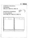
68 and68V oil-FiredBoilerManual
lncludes:
. Installation
o Start-up
. Service
o Parts
-
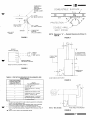
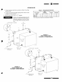
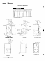
68 BOILER
REARFLUEOUTLET
68V BOILER
TOP FLUEOUTLET
J
Any claims for damage or shortage in shipment must be filed immediatelyagainst the
transportationcompany by the consignee.
Part No. 550-110-49410487WP
-ffiTableof Contentsv
Air Supplyfor Combustion. . . .
Chimneyor Vent Requirements
S t a n d a r dM i n i m u mC l e a r a n c e s
BoilerFoundaton
Placement
HydrostaticPressureTest..
C o n t r oTl a p p i n g s T a b l e .
BreechingErection
WaterBoiler
MultipleZoningWith Circulators. . .
System
Use With Refrigeration
BypassPiping .
SteamBoiler
ReplacementBoilerConnections.
J
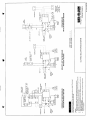
WiringDiagram
'.'.15
4
4
.........4
.....4-5
....5
........6
8-9
.9
10
10
11
12
WaterTreatment...
FreezeProtection
FillingWaterBoilers
FillingSteamBoilers
BurnerAdjustment
S k i m m i nSg t e a mB o i l e r s. . . .
......16
16
.......16
......16
........16
..... 16
Check-OutList...
lnstallationandServiceCertificate
........17
....... 17
Ratings
68Dimensions.....
68VDimensions....
.....19
...18-19
......20
68 Boiler
6 8 VB o i l e r .
Whencallingor writingaboutthe boiler'
IMPORTANT:
PLEASEGIVETHE MODEL,SERIES,AND C.P. NUMBER, located on the boiler nameplate.
21
22
Any reuse or reproduction of the artwork and copy in
this manual is strictly prohibited without the written
consentof Weil-McLain.
DO NOT USE PETROLEUM-BASEDCLEANINGOR SEALINGCOMPOUNDSIN BOILERSYSTEM.
SEVEREDAMAGETO THE BOILERWILL OCCUR.
-2-
U
v
-wnThe following definedterms are usedthroughout this manual to bring attention to
the presenceof hazardsof various risk levels,or to important information concerning the life of the product.
J
indicates presence of a hazard which
will or can cause minor personal injury or property damage if ignored.
indicates presence of a hazard which
rli11 cause seuere personal injury,
death or substantial property damage
if ignored.
indicates special instructions on installations, operation, or maintenance
which are important but not related to
personal injury hazards.
indicates the presence of a hazard
rvhich coz cartse seuere personal injury, death or substantial property
damage if ignored.
FAILURE TO FOLLOW ALL INSTRUCTIONSIN PROPERORDER CAN CAUSE PERSONAL INJURY OR
DEATH. READ ALL INSTRUCTIONSBEFORE INSTALLING.
l: Pre-lnstallation
Section
CODES
J
Installations must comply with all local codes,laws, regulations and ordinances. When required, the installations must
conform to American Society of Mechanical Engineers Safety
Devices for Automaticallv Fired Boilers. No. CSD 1.
AIR SUPPLYFORCOMBUSTION
Adequate combustion and ventilation
air must be provided to assure proper
combustion and prevent the possibility of flue gas spillage.
Exhaust fan must not be used in
boiler area.
1 . In buildings of conventional frame, masonry or metal construction, infiltration is normally adequate to provide
combustion air for boilers in unconfined rooms.
2 . If
the space is in a building of unusually tight construction, air should be obtained from outdoors or from spaces
which freely connect with outdoors (see 4 below).
For boilers in confined rooms, two permanent openings
shall be provided: one within 12 inches from the ceiling
and one within 12 inches from the floor of the room. Each
opening shall be at least one square inch per 1,000 BTUH
(140 sq. in. per 1 GPH) boiler input, but must not be less
than 100 sq. inches. These openings shall freely connect
with areas having adequate infiltration from outside.
v
4 . When all air is provided from outdoors the confined space
shall be provided with two openings as outlined above.
These openings shall connect directly or by ducts with outdoors or spaces(crawl or attic) that freely connect with the
outdoors and shall be of the size listed below for that particular arrangement:
(a) One square inchper4,000BTUH(35 sq. in. per 1 GPH)
ofboiler input for direct outdoor air supply through an
outside wall or through vertical ducting directly to
outside.
(b) One square inch per 2,000 BTUH (70 sq. in. per 1 GPH)
ofboiler input for direct outdoor air through horizontal ducting.
(c) All ducting shali be of the same size as the opening to
which it is connected with minimum dimensions of no
Iessthan 3 x 3 inches or 9 total square inches ofarea.
(d) Other size ducting must comply with local codes.
5. For boilers installed in closets, alcoves, undercounters,
etc., see pages 6 and 7.
CHIMNEYOR VENTREQUIREMENTS
Designed
for NATURALDRAFTFIRINGONLY.Usea Class
A chimney.
Minimum chimney or vent sizes:
Boiler sizes 2 -7 - 8" x 8" square (6:11x 63h inside liner) or 8"
round
15 feet high
Boiler sizes 8-g - 12" x 12" square (105/sx 105/ainside liner)
or 12" round
20 feet high
In most cases a chimney or vent extended at least 3 feet above
the highest part of the roof or other structure within 30 feet
will be sufficient to prevent downdrafts. Increase chimney
cross-sectional area and height at least 4 percent for each
1.000 feet above sea level.
Inspect existing chimney or vent before installing new boiler. Failure to
remove blockage, clean, or replace
damaged pipe can cause severe injury
or death.
An induced draft fan may be necessary if:
1) Excessive resistance to flow of combustion gases can be
expected.
2) Cross-section area of chimney is smaller than minimum
recommended.
3) Chimney height is less than recommended.
Ifan induced draft fan is used, overfire draft should not exceed
-.02 inches water column.
-3-
-ffi.-FRONT OF
\\ FOUNDATION
SELECTTHEBOILERLOCATION
TO THE BOILERBEALL CONNECTIONS
CONSIDER
FORE SELECTING A LOCATION.
--7
To avoid personal injury, death or
property damage, keep boiler area
clear and free from combustible materials, gasoline and other flammable
vapors and liquids.
,'M
IN
STANDARD MINIMUM CLEARANCES
24 inches-front and top
6 inches-Flue pipe to combustiblematerials.
6 inches-Right and left sides (except steam with tankless
heater)
15 inches-Left side for steam with tankless heater.
6 inches-Back (top outlet)
SPECIAL CLOSE CLEARANCES-See Pages 6and 7.
RESIDENTIALGARAGEINSTALLATION
Install boiler so burner is at Ieast 18
inches above the floor.
BOILER
FOUNDATION
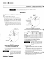
Boiler may be installed on non-carpeted combustible flooring.
Boiler legs provide approximately one inch air space for natural aeration.
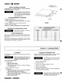
Boiler must be installed on level surface. If non-level conditions exist or ifarea could flood, build LEVEL concrete or solid
brick foundation. See Figure 1 and Table I.
a
2"M lN
F I G U R E1
BOILERFOUNDATIONSIZES
TABLE I
L = Lenoth of Foundation
All Other Boilers
PackaqedWater Only
Boiler Size
268
12112"
368
468
568
668
768
15112"
15112"
15112"
18112"
18112"
21112"
21112"
24112"
24112"
27112"
3O1lz"
868
968
33112"
Boiler
ll: Installing
Section
PLACEMENT
Position boiler close to chimney. Provide minimum clearances
as indicated.
W'hen transporting with crate removed, do not tip boiler forward.
Damage to burner may result.
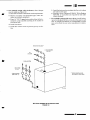
For 8 and 9-section blocks:
1. To split block:
a. Removecleanout plate.
b. Remove8) 5112"tie rods.
c. Pull block apart. Save rods, nuts, washers,elastomer
seals,and copeseal.
2. Move divided block to location.
3. Reassemble:
a. Clean port openingswith dry rag. DO NOT USE OIL.
Placeelastomersealsin port openings.
b. Re-formcopeseal and place in sealing groove.
c. Draw sections together evenly until metal-to-metal
contact is made at nipple ports.
d. Replacecleanout plate.
-4-
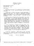
PRESSURE
TEST
HYDROSTATIC
Pressuretest BEFORE attaching piping or electrical supply
Install, but do not hook up, tankless heater (ifused).
DO NOT pressure test with water
level control installed. Damageto control can occur.
1 . Removeshipping nipple.
2 . Install drain valve.
3 . Install valve at highest tapping to vent air.
4 . Connect water supply.
5 . Plug remaining tappings.
6 . Fill boiler. Vent all air. Test at 1Vztimes working pressure for more than 10 minutes.
DO NOT LEAVE BOILER UNATTENDED.Cold water fill couldexpandand causeexcesspressure.
u.
rffiv
TABLE II CONTROLTAPPINGS
7. Check for maintained gaugepressure.
8. Check for leaks. Repair if found.
c
Repair leaks at once. Damage to boiler
can result. NEVER use petroleumbased stop leak compounds. Seal damage and leakage between sections wiil
occur.
9. Drain boiler and removetesting plugs.
10. On initial start-up, check for leaks in system piping. If
found.repair at once.
STEAlvl
WATER
LOCATION SIZE
314"
Drain
Drain
D
(in plate)
1 112"
High-LimitControl
(bushedto qa")
SkimTapping
D
(in water
314"
CombinationHigh-Limit
and OperatingControl
healer)
h
CombinationPressure
Gauqe
and TemDerature
PressureGaugeand
PressureLimitControl
K1
314"
Water Flelief Valve
GaugeGlassand/orLowWaterCuloff(bushed
lo 112")
n2
314"
Plugged
GaugeGlassand/orLowWaterCutoff(bushed
lo j/2")
3t4"
To CompressionTank
Steam Relief Valve
N
HeaterOperatingControl
(368through568
Boilers)
314"
(rnsteam
heater)
U2
314"
HeaterOperatingControl
1648-q68Boilers)
Plugged
A
v
I
tri
Z
LA
u-"
-a
SUPPLY
ll
lr
WATER
HEATER
K2
f-l
tt
ut
ll
STEAM
HEATER
SECONDARY
AIR
SHUTTER
|
'-(
o-l---
It
trB
,lj
i
ll
t _ J _ _ __ _ _ _ ,
F I G U R E2
v
-o-
-
-
JACKETASSEMBLY
boilers)
(Fornon-Packaged
Refer to jacket erecting instructions packed in the jacket carton.
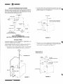
Connectionmust be abovebottom of chimney to avoid blockage. Breeching must not enter chimney far enough to cause of,struction.Use a thimble or slip joint wherebreechingenters Q
the chimney to allow removal for cleaning.
Avoid long horizontal breechings,excessivenumbers of elbows or tees, or
other obstructionsrestricting flow of
combustiongases.
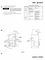
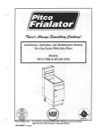
B R E E C H I N GE R E C T I O N
(68)-see
Figure 3.
Back outlet
Top outlet (68V)-see Figure 4.
Use full-sizedbreeching(P-268can be reducedto 5 inches)'See
page3 for chimneysize.
P I T C HU P
tln" PER LINEARFOOT
B A R O T / il ' F l. - ' r r F i a F i c o N - l - R o -
,z/-!-\\
t-]
L-,
i
'
DR LL SN/AIL HOLE TO MEASURT
co2, BRttcHNC DRAtr ANU SMOKE
M:N
8
t
lll
56
F I G U R E4
CONNECTION
68V BREECHING
F I G U R E3
68 BREECHINGCONNECTION
Installation
Clearance
lll:Close
Section
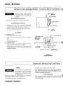
Water boilers can be located in close-clearance areas (such as
alcove. closet, under counters, etc.) only when all instructions
in this section are followed. Substitute these instructions for
corresponding material in manual. All other procedures and
practices must remain the same.
1 . Install boiler using clearances listed.
2 . Install
barometric control 18-20 inches from boiler in
breeching.
.f.
Standard minimum clearances (shown on page 4) should be
used where possible. Where closer clearances are required:
less than 24" are available, provide removable surface to allow for cleaning boiler
flueways. Distance between combustible surface and boiler can be no less than 2 inches.
Right and/or left side-2 inches minimum.
Front of boiler-2 inches minimum from burner.
Double-wall flue pipe to combustible surface-as listed in Table III and Figures 7 and 8 or 9.
Top of boiler-if
Flue pipe clearances must take prece'
dence over jacket clearances.
-6-
A
Obtain and use kit, part no. 386-500-050.
a. Attach manual reset temperature switch near upper
sudace ofenclosed area. See Figure 5.
b. Install switch leads to burner primary control. See Figure 6.
Provide two fresh air openings when installing in confined space. Size each opening one square inch per 1,000
BTU (140 sq. in. per 1 GPH) input. Locate openings near
top and bottom of enclosed space.
TO THE HOMEOWNER: If red
button on manual reset temperature switch has poppedout, CALL a
YOUR SERVICEMAN IMMEDI- :
ATELY.
COMBUSTIBLE
SURFACE
(COUNTERTOP;
C E I L I N GI N
ALCOVE,CLOSET,
-ffiC O M B U S T I B LS
EU R F A C E
v
# 6 x r / zP H I L .
S H T METALSCREW(2)
I TO5 INCHES
t
PROTTCTION
M A N U A LR E S E T
T E M P .S W I T C H
#10 x 1l2PHlt.
S H T .M E T A LS C R E W
COMBUSTIBLE
SURFACE
( W A L LO R C A B I N E T )
BRACKET
DOUBLE-WALL
VfNT PIPING
N O T E : D i m e n s i o n" A " - DesiredClearanceAs Shown in
T a b l el l l .
F I G U R E5
F I G U R E7
BURNER
PRIIVARY
CONTBOL
MANUAL
RESET
T E M P .S W I T C H
TOt\.-
2 4 " F O RS E R V I C I N G
O B M I N I M U [ /2l " F O B
C L O S EC L E A R A N C E S
FO
FO
U
*G
B E M O V EJ U M P E R
ANDTNSTALLCONTROL
R E F E BT O W I R I N GD I A G R A MP, A G E1 5 .
I
F I G U R E6
I
COMBUSTIELE
SURFACE
TABLEIII PROTECTION
REQUIRED
FORCLEARANCES
LESS
T H A N6 I N C H E S '
WHENDESIREOMINIMUM
CLEARANCEFROMDOUBLEWALL VENT PIPETO
COMBUSTIBLESURFACEIS:
> S E E T A B L EI I I A N DF I G U R E7
F I G U R E8
USETHE
FOLLOWINGPROTECTION''
3"
1/4 insulating millboard"
spaced out 1 "I
3"
28 gage sheetmetalon 1/4"insulating
millboard"'
2'
28 qaqe sheel metal spaced out 1 I
2"
28 gage sheel metalon 1/8"insulating
m i l l b o a r d ' " 's p a c e do u t 1" I
2"
22 gage sheetmetalon 1" mineralwool
bats reinforcedwith wireor equivalent
2 1 " f -O ? .
SiRVC \C OF
I'/ N 2'' FCR
RT[lOVABLI
SURIACE
l / 4 " i n s u l a t i n qm i l l b o a r d '
v
NOTES:
' All clearancesmeasuredfrom outersurfaceof equipmentto combustible
surface,not to the protectionused.
" Applyto combustiblesurfaceunlessotherwisenoted.Coverall surfaces
a s s p e c i f i e di n T a b l el l l a n d F i g u r e7 . T h i c k n e s s easr e m i n i m u m .
"'
Factoryfabricatedboardmade of noncombustible
materials,normally
fibersh
, a v i n gt h e r m acl o n d u c t i v i tiyn r a n g eo t 1 B T U i n c hp e r s q . f t . p e r o F
or less.
I
material.
Spacersshall be madeof noncombustible
> S E E T A B L EI I I A N DF I G U R E
N O T E : 2 " M l N .O N S I D E S
F I G U R E9
-7-
-ffi-
lV:Piping
Connections
Section
Failure to properly pipe boiler may result in improper operation
and damageto boiler or building.
WATERBOILER
Boiler has built-in air elimination system. A separate air eliminating device is not needed if expansion tank is piped as
shown.
Refer to table IV and Figures 10 and 11.
1. Size expansion tank to system design requirements.
Undersized expansion tanks cause system water to be lost
from relief valve and make-up water added through fill
valve. Eventual section failure can result. Expansion
tank installation:
from the :]/+"
a) Closed type expansion tank-connect
N.P.T. tapping "N" to the expansion tank using r7""
N.P.T. piping. Horizontal expansion tank piping must
pitch upward toward tank at least 1 inch for each 5 feet
of piping.
C L O S E DT Y P E
TANK
EXPANSION
C L O S E DD I A P H R A G M
PRE-PRESSURIZED
T Y P EE X P A N S I O N
TANK=-
CIRCULATOR
F I G U R E1 1
P I P I N GC O N N E C T I O NFSO RW A T E RB O I L E R S
W I T HC L O S E DD I A P H R A G M
PRE-PBESSURIZE
TD
ANK
TABLE IV
Boiler
Size
268t268V
368-468/368V-468V
568-768/s68V-768V
868-968
'WATER BOILERPIPESIZES
1"N.P.T
1"N.P,T
Piping to
Expansion
Tank"C"
3 / + "N . P . T .
' 11 / + "
N.P.T.
1 1 / a "N . P . T .
3 / + "N . P . T .
1 1 / 2 "N . P . T .
1 1 / 2 "N . P . T
3 / a "N . P . T .
Supply
Pipe Size
"4"
Return
Pipe Size
"8"
3 / a "N . P . T .
. M i n i m u mp i p es i z ew i t h2 0 o Ft e m p e r a t u rrei s et h r o u g ht h e b o i l e r
2" N.P.T
11/2N
" .P.T.
2. Connectsupply, return and cold water fill piping.
3. Install water relief valve in K1 tapping.
F I G U R E1 O
FORWATERBOILERS
PIPINGCONNECTIONS
WITH CLOSED.TYPEEXPANSIONTANK
b) Closed diaphragm pre-pressurizedtype expansion
tank-may be locatedanywherein the system,preferably near the boiler.
A manual or automatic type air vent
must be installed in the 3/a" N.P.T.
tapping "N" when a closeddiaphragm
pre-pressurizedtank is used.Refer to
Figure 11.
-8-
Relief valve discharge piping must be
piped near to the floor or to a floor
drain to eliminate potential of severe
burns. Do not pipe where freezing
could occur.
4. Iow water cutoff:
i) Should be installed if boiler is located above radiation
level.
ii) May be required on water boilers by certain state, local
or territorial codes or by insurance companies.
Use a low water cut-off designed for water installations.
An electrode probe type is recommended. Install in a tee
in supply piping above boilers.
5. If the system is to comply with ASME codes, an additional high temperature limit is needed. Purchase and install in supply piping from the boiler.
t
-ffio.
t
For multiple zoning with circulators, these changes
must be made (seeFigure 12):
a) Sizeeachcirculator to individual circuit requirements.
b) Remove circulator and preformed pipe (when furnished as standard equipment).
c) From 1Vz' N.P.T. tappedreturn inlet at front of boiler,
construct a pipe manifold accordingto the number of
circulators used.
d) Install circulators.
e) Install flow control values to prevent gravity circulation.
f) Install balancingvalvesto adjust the flow soit is about
the same in eachzone.
g) Separate relays (Honeywell R845A, White-Rodgers
829A-845,or equivalent) are required for each additional circulator.
7
For multiple zoning with zone valves, install balancing valvesto adjustthe flow soit is aboutthe samein each
zone. A separatetransformer is recommendedto power
zonevalves. Refer to zonevalve manufacturer's instructions.
ISOLATIONVALVES--
FLOWCONTROL
VALVES-'
FROMSYSTEM
ISOLATION
VALVES..
- -MAYBE INSTALLED
IN
CIBCULATORS
( s E E S T E P' b ' )
ALTERNATELOCATIONS
MULTIPLEZONINGWITH CIRCULATORS
F I G U R E1 2
U
-9
-
-wllSYSTEM
USEWITHREFRIGERATION
The boiler must be installed sothat chilled medium is piped in
parallel with the heating boiler with appropriate valves to
prevent the chilled medium from entering the boiler. Consult
I:B:R Installation and Piping Guides.
f-ExPANso[]')
\I
TANK
2 . To protect
boiler from condensation formed by low water
temperature returned from large water content converted
gravity systems, etc., see Figure 15.
)
t
IO SYSTEM
CIRCULATOR
VALVE'
SHUT.OFF
VALVE
- A D J U S TV A L V E ST O M A I N T A I N
1 6 0 0 FO R G R E A T E RI N B O I L E R
VALVE'
')
STRAINER
C H E C KV A L V E
HEATING
BOILER
DK
CIRCULATOR
R E T U R NP I P E
F R O I VC O M B I N A T I O N
H E A T I N G& C O O L I N GU N I T S
F I G U R E1 3
P I P I N GF O RC O M B I N A T I O N
NY) S T E M S
H E A T I N G& C O O L I N G( R E F R I G E R A T I OS
F I G U R E1 5
BYPASS PIPING
BYPASS PIPING IS NOT NORMALLY REQUIRED ON
TYPICAL BASEBOARDSYSTEM.
Bypasspiping should be usedfor the following installationsBypass,supply, and return piping should be same size.
3. To protect boiler from condensation while protecting system from high n'ater temperatures, as in large water content radiant ceiling panels, see Figure 16.
1. To protect system radiant panels,plaster, etc. from high
temperature water suppliedfrom boiler, seeFigure 14.
IU
SYSTEM
- A D J U S TV A L V E ST O
M A I N T A I N1 6 0 ' F O R
G R E A T E RI N B O I L E R
FROM
SYSTEM
12"
MAX,
SYSTEM
T E M P E R A T U RG
EAUGE
TO SYSTEM
FROM
SYST
CIRCULATOR
CIRCULATOR
t
F I G U R E1 4
-10-
F I G U R E1 6
-ffiSTEAMBOILER
J
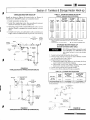
1 . Connect piping near boiler as shown in Table V and Fig-
TABLE V STEAMBOILERPIPESIZES
ures 17 or 18.
Riser
Pioe Size
Header*
SteamBoilet
H
B
A
Size
368-768
2112"
z
868-968
'24" minimumfromwaterlineto the bottomof header
2 . Connect cold water
fill supply piping close to boiler in the
condensate return piping.
3. Install steam reliefvalve in "N" tapping.
Relief valve discharge piping must be
piped near to floor or to a floor drain to
eliminate potential of severe burns.
Do not pipe where freezing couid occur.
R I D U C I N GE L B O W
n
TO
SYSTEf,I
J
1I
F I G U R E1 7
P I P I N GC O N N E C T I O N S
FORSIZE 3-7 STEAMBOILERS
24
MIN
26 1/8"
WAIER
L I NI
)
^l
l-
1I
\-
CONDENSATE
RITURN
SHORT
NIPPTE
BACK OF
BOILER
RIDU CING E L E O W
/n
TO
SYSTtM
J
1I
24
[/ lN
+
F I G U R E1 8
P I P I N GC O N N E C T I O N S
FORSIZE 8-9 STEAMBOILERS
t
T
I
CONDTNSATE
RETURN
26-7 /8"
WATIR
L I NT
SHORT
NlPPLI
BACK OF
BOILER
-11-
Equalizer
J
11|a"
11Ia"
-wllCONNECTIONS
BOILER
REPLACEMENT
STEAMSYSTEM
ONE.PIPE
t
Recommended piping for replacement boiler on older one-pipe
steam system is shown below.
Some installations may require an added water tank for additional steaming capacity. By installing two plugged tees as
shown in Figure 19, a tank can easily be added ifnecessary.
Obtain Bulletin AE 8403 from your Weil-Mclain
for tank sizing.
distributor
H E A D E RA N D S U P P L YR I S E R S
SAME SIZEAS OLD SYSTEM
- O R P E RA S H R A E
RECOMMENDATIONS
R E D U C I N GE L L
4
ELL
REDUCING
t
\,r
7
P I P I N GT O O P T I O N A L
RESERVOIR
TANK
q- --
\
t
/
N O R M A L L YP L U G G E I
NOTE:
NOTSHOWN
JOINTS
SWING
F I G U R E1 9
RECOMMENDED
PIPINGFOR REPLACEMENT
STEAMBOILER_ONE-PIPESYSTEM
-L2-
tl
EffiHook-up
Heater
V: Tankless
& Storage
Section
t
TABLEVI STEAMAND FORCEDHOT WATER
BOILERTANKLESSHEATERRATINGS
TANKLESS HEATER HOOK.UP
Install as shown in Figure 20 (water boiler) or Figure 21
(steamboiler). 2681268Vcannot use a tankless heater.
'lntermlttent
1. Install automatic mixing valve.
2. Install flow regulating valve. Size accordingto intermittent draw of heater as shown in Table VI.
3. Operating control with a small differential scaleis recommended.Install in temperature control tapping in heater
plate.
4. In hard water areas,it is advisableto softencold domestic
supplywater to tanklessheaterto preventlime build-up.
FLOW
coLD
FEGULATINGWATER
VALVE
SUPPLY
Heater
No.
Draw GPM
100oF. Average
Temp. Rlse
WATER
368/368V
468/468V
568/568V
668/668V
768t764V
868-968
E-624
E-624
E-624
E-626
E-632
E-632
3.00
3.25
3.25
3.50
4.25
4.50
2.O0
2.70
3.30
4.00
4.60
4.75
STEAM
368
468
568
668
768-968
35-S.29
35-S-29
35-S29
35,S29
3s-s-29
3.00
3.25
3.50
375
4.00
2.OO
2.70
3.30
4.00
4.60
"
IemperaIUre.
Continuous draw-no
+JACKET
.
FFONT
recovery period
HEATER
MIXED
MIN,
t
112"
sl4"
112"
112"
314"
112"
112"
E4"
314"
112"
34"
g4
314"
314
314'
314
314'
314
84"
314
314"
I
Not avarlable on 268/268V boilers
62-2-EStorageHeater cannot be used
with 268i268V thru 568/568V forced
hot water boilers or any size steam
IEE
OUTLET
Temp.
Control
Taooino
STORAGEHEATERHOOK.UP
(forced hot water boiler only)
CONTROL
,"o., ---I-I
lnlet
and
Outlet
Taooinos
ratingsbasedon 60 PSIGdomeslicwaterpressureat heater.
Werl-McLain
' Gallonsol waterDerminuteheatedlrom 40o lo 140oF.wilh 200"F boilerwater
INLE\
BRASS
ELBOW
"Continuous
Draw GPM
10 0 . F
Temp. Rise
Boilerl
Size
_t
COLD
F I G U R E2 0
TANKLESSHEATERPIPING(WATERBOILER)
boiler.
1 . Locate tank as high as possible above boiler.
2 . Vertical type storage tank can be used ifbottom oftank
can be located above top ofboiler.
3. To provide gravity circulation:
a) Horizontal supply from heater to tank must pitch upward 1 inch for each 10 feet ofpiping.
b) Horizontal return from tank to heater must pitch
downward 1 inch for each 10 feet of piping.
4. Locate return piping above storage heater.
5. Use as few elbows and pipe fittings as possible
TABLEVII STORAGEHEATERRATINGS
Boiler Size'
:/a" TEMPERATURE
668 968
668V-768V
TAPPING
180o Boiler Water
Healer Capaclty
Gallons
40o-1 40o Rise
Storage
Heater
Number
62-2-E
50 in 3 Hours
212' Boiler Water
Hester Capacily
Gallons
400-140" Rlse
70 in 3 Hours
Recommended
75-125 Gallons
StoraqeTank
50-90 Gallons
'No. 62-2-Estorageheatercannotbe usedwith 268/268Vthrough568/568Vwaterboilersor
COLD
WATER
SUPPLY
I
I
with any steamboilers.
PREssUAE
,i;*
L
lnt
E
TEMPER^TURE
A
+ }l_
!'1-
{re
F_
OP€RAI
\
r
II
t-
t
;iru?.
'gl!9!
NC
n
{t
AUTOMATIC
MIXING
VALVE
xor
COLD
F I G U R E2 1
TANKLESSHEATERPIPING(STEAMBOTLER)
-13-
,,
'F^'t
-ffi-
Installation
& Burner
Boilers-Control
Vl:Non-packaged
Section
*x
' s rurppue
(aRess)
Failure to properly install, pipe and
wire boiler controls may result in severe damage to boiler, building and
personnel.
jree (aness)
WATERBOILERCONTROLS
1. Install control where shown on tapping table, page 5.
STEAMBOILERCONTROLS
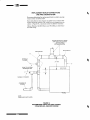
1 . Connect a low water cut-off to gauge glass tappings Kl
and K2. Refer to Figure 23. Follow instructions packed
with control. Pipe drain near the floor or floor drain.
Install the pigtail syphon, pressure gauge and steam pressure limit control' See Figure 23'
jrt
NIPPLE
(BRAss)
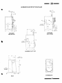
OIL BURNER
For B-68/68Vboiler:
1. Placegasketover end ofair tube.
2. Looselyscrewthree mounting bolts into boiler mounting
plate.
Mount burner.
A
HIGH LIMIT
PRESSURE
CONTROL
Tighten mounting bolts.
For A-68/68V boiler:
1
STEAM GAUGE
FoR
olxrjNreer-E
Secure universal mounting flange and gasket to burner
mounting plate. Use three bolts provided.
Position burner so it is level to 1112"tilt downward' Air
tube should be flush to 1/ainch recessedfrom inside wall of
combustion chamber.
;fstneereuu
* x g t t t P P u e- '(ennss)
f srneerELL e{,
jree
LOW WATER
C U T . O F F* 6 7 W P
FIGURE
23
STEAMCONTROLS
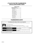
Vll: Wiring& FuelLinePiping
Section
WIRING
For your safety, turn off electrical
power supply at service entrance
panel before making any electrical
connections to avoid possible electrical shock hazard.
Wiring must comply with the National Electrical Code and
any additional national, state, or local codes.
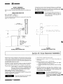
Seewiring diagram, page 15 for proper wiring.
-14-
All safetycircuit wiring must be N.E.C.Class1.
For any additional electrical safetycontrols,use No. 14 gatge
wire. Electrical supply wiring to burner should be No. 14
gaugeor heavier with fused disconnectswitch. Be sure boiler
is properly groundedat switch box.
FUELLINEPIPING
Referto separateburner manualand any local or national t/
code requirements which may apply to sizing and installing
the fuel line piping.
=
N
E.^a
I
*i3a9.
I;;
E
F
q
u
EEE
lrJ
F
UUY
o >;.
<;
F
Ez
zi
tI-_
-v*
HF
-JF
oO
Et
ae
-6
ox
OY
ZP^ EF
;Y
o
(5
5,i=
cU JH:
oiF
dl
@
s
o
$
o
U.9
tr
qr
I
-
rr:
F
d E . --
TFS:H
>Xz5{
ts6r
F
)
-RF
TZzsA
ef
tt *tf
=
fF;E=
oO
@
z
I
F
E
=
o
I
I
l
E:
o
P
OF
=F>
@ii
3za
m3
Lz
=
]o
)
UJ!H
:R
3+
9s
=t
Y6
iio
1"1
tl
l-f
9=
I
F
l^
oo
.
. O
=G
>F
=6
)
o
e
(r
UU;
o>;r
G
o
(r
o
o
(,
z
tr
=
(r
.1tr
uJ
O : F
I
fro
f@
|Jl
l
@
<u
=C
U
5
x+
t.U
J
5*3
co
OE
Ez
!go
9
J
o
-(r
trH
!!<
c)
o
LrJ
(r
EH
+
=;
Ff
oo
II
>E
F=
E
(,
TZ
OF
H
3
)Z
>P
0€
.969
q
c
=?
T;
i 1U E
Bll
@a
?z
>P
za
5
o
I
c
lJ
E6
f
o
E
>
;<
eoE
f
L
tr
E
zEU
o>
F *-G
<='- o
z=*
@-i
t
:
G
o\
-p
=
.<E
oiiF
<*!!
fir
o<
$e
rE
oooooo
: N6 N
u
0 -i :NENO
9=
fi9
o+
5
E=
e=
,
qa
ol
>H
E5
I
-
Ai
;
P
E
x
*='
6
SE E E
6
,q:
I
ouJ
Er
IIJ F
Ff
t
3\
UUY
a>;,
Eb
E
E
:o
o
>
E
9
iY-:o
.:
i;
x
-E*8E u.
:.
,=
.,
Y
9
gl.s
-r
ov
=
!E
o
:
:
6
E 8 9 ;5
=
6
E;r4
il:
iqt,E 5.
sl
26.82 ;
E:
E9EP..g
: q a#?3EE
SE' EE;EEP!
:E
E!EEEeE"
+x
9F)::y;
O
nr
"*
--
-
X
iri
P
.=6e;nen
5gE=E+#=*
-ffiAdjustments
Vlll:Final
Section
ADJUSTMENT
BURNER
WATER TREATMENT
Never use petroleum based stop-leak compounds. Water
seal deterioration will occur, resulting in leakage between sections.
Final burner adjustments must be
made using combustion test equipment to assure proper operation. DO
NOT FIRE BOILER WITHOUT WA.
TER OR SECTIONSWILL OVER.
Continual make-up water will reduce boiler life. Minerals can
buiid up in the sections, reducing heat transfer, overheating
the cast iron, and causing section failure.
HEAT.
For unusually hard water areas or low pH conditions (less
than 7.0) consult local water treatment company.
Freeze protection
(when used):
Use antifreeze especially made for hydronic systems. Inhibited propylene glycol is recommended. DO NOT use undiluted
or automotive type antifreeze.
507o solution provides maximum protection to about - 30'F.
Local codes may require a back-flow preventer or actual disconnect from city water supply.
Determine quantity according to system water content. Boiler
water content is listed on page 18.
Follow antifreeze manufacturer's instructions.
FILLINGWATERBOILER
1. Close manual air vents, drain cocks, and automatic air
vent, if used.
Z.
Allow boilers to heat to design conditions.
Using combustion test equipment, adjust burner for:
a) 0 smoke with maximum COr.
b) - 0.02 inches W.C. negative draft overfire.
SKIMMINGSTEAMBOILER
Clean newly installed steam boiler to
remove oil and grease. Failure to properly clean can result in violent fluctuations ofwater level, water passing into
steam mains, or high maintenance
costs on strainers, traps and vents. Do
il?JJ."
productt
t"
petroleum
based
with each application.
1. Provide 11/2" piping from boiler skim tapping to floor
drain.
Open automatic air vent two turns, if used.
2. Adjust waterline to midpoint of skim piping.
2 . Fill to correct system pressure. Correct pressure will vary
t).
Refer to burner manual for start-up. Adjust air band to
provide a clean yellow flame without smokey tips.
4 . a) Starting on lowest floor, open air vents one at a time
until water squirts out. Close vent.
b) Repeat with remaining vents.
Refill to correct pressure.
6 . Close, then open automatic air vent, if used, one full turn
for normal boiler operation.
FILLINGSTEAMBOILER
1. Do not fill (except for leakage tests) until boiler is ready to
be fired.
2. Fill to normal waterline, halfway up gauge glass.
3. Fire boiler to maintain a temperature below steaming
rate during skimming process.
4. Feed in water to maintain water level. Cycle burner to
maintain temperature below steaming.
5. Continue skimming until discharge is clear. This may
take several hours.
6. Drain boiler. While boiler is warm but NOT HOT, flush
all interior surfaces under full pressure until drain water
runs clear.
7. Remove skim piping and plug tapping.
3. Boiler water pH 7.0 to 8.5 is recommended.
8. Close drain cock. Fill with fresh water to waterline. Start
burner and steam for 15 rninutes to remove dissolved
gases.Stop burner.
4. Follow skimming procedure.
9. Check traps and air vents for proper operation.
-16-
G
-ffiProcedure
lX:Check-out
Section
)
PROCEDURE
CHECK.OUT
(Check-offstepsas completed.)
n
tl
Water boiler:
a. System properly filled with water?
7. Limit control set to design temperature or pressure requirements of system? Maximum limit setting
-240'F. (water boilers)-15 psi (steam boilers).
b. Air purged from system?
c. Automatic air vent, if used, open one turn?
u2
8. For n"rultiple zones, flow adjusted so it is about the
same in each zone (water boilers only)?
Steam boiler:
ii. Boiler properly filled rvith rvater?
9. Thermostat heat anticipator set properly? Refer to
wiring diagram.
b. Svstem vents operating properly'?
c. Boiler properly skimmed?
'a
6. Test ]imit control: While burner is operating, move indicator of limit control below actual boiler water temperature or pressure. Burner should go off. Circulator
should continue to operate (water boilers only). Raise
limit control above boiler water temperature or pressure and burner should reignite.
tl
Air purged lrom oil piping? Piping checked for leaks?
I'-
A
Proper draft and burner flame? Final adjustment
made with combustion test equipment?
L]
D.
Test safety controls: If boiler is equipped with a low
water cut-off or additional safety controls, test for operation as outlined by manufacturer. Burner should
be operating and should go off when controls are
tested. When safety devices are restored, burner
should reignite.
10. Boiler cycled with thermostat? Raise to highest setting. Boiler shouid go through normal start-up cycle.
Lower to lowest setting. Boiler should go off.
LI 11. Several operating cycles observed for proper operation?
L ] 12. Room thermostat set to desired temperature?
t_ 13. All instructions shipped with boiler reviewed with
owner or maintenance person, returned to envelope
and given to owner or displayed near boiler?
LJ 14. On initial start-up, check for leaks in system piping. If
found. renair at once.
Installationand ServiceCertificate
B O I L E RM O D E L
B T UI N P U T
CP NUMBER
SERIES
DATEINSTALLED
L l Installation
havebeenfollowed.
instructions
E
Check-outsequencehas beenperformed.
I
Abou" information
is certiliedto be correct.
n
receivedand leftwithowner/maintenance
lnformation
oerson
lnstaller
(Company)
(Address)
(Phone)
(lnstaller'sSignature)
-17-
[HIl-
-
X:Ratings-Data
Section
r}
@,
N E TI = B = B R A T I N G S -
iDOE HEATING
I=B=B
MBH
CAPACITY
BOITER
STTAM STEAM WATEB
BURNER
CAPACITY
MBH
WATER s0.FT. MSlt
GPH
STEAM
NUMBER
PREFIX
74.8
oo
o.70
P
268t268V
14
368
368V
0.95
0.9s
113
A,B,
P
468
468V
1.25
1.25
149
A,B,
r
568
568V
1.50
1.50
179
A,B,
P
668
668V
1.80
216
A,B,
P
2.05
2.05
246
?48
248
770
768V
A,B
868
230
2691
2691
A,B
968
2.55
298t
2981
A,8,
f
/od
84.8
JC3
14
51
51
a:
181
.t
8l
':'
218
675
111.8
SIZE
INCHES
8x8
99.1
99.1
8x8
31.3
8x8
8x8
8x8
HEIGHT
FEET
WATER
P6St''qprB-63l/
TA rt B{S
15
7.O
15
15
't5
13.3
3.3
3.3
11.2
4.9
4.9
12.4
8.6
10.2
't0.2
6.5
6.5
13.6
IJ.J
8.6
l5
'15
STEAM
(ToWalerline)
157.4
157.4
8x8
8x8
15
189.6
189.6
8x8
5
5
1.8
1.8
8 .1
8.1
14.8
8x8
184.5
215.7
215.7
8x8
8x8
5
5
3.4
3.4
9.7
9.7
to. I
840
201.8
233.9
930
223.6 2 5 9 . 1
134.3
162.0
218
1.80
(GAt.)
EOILERWATERCONTENT
l=8=RCHIMNEY
12
12
20
zt.J
17.4
20
22.9
18.6
t
Basedon standardtest proceduresprescribedby the UnitedStatesDeparlmentof Energyat combustionconditionof 130/oCOz
I
e f 1. 3 3 3 .A n a d d i t i o n aal l l o w a n c se h o u l db e m a d ef o r u n u s u apl i p i n g
e l 1. 15 . S t e a mr a t i n g sa r e b a s e do n a n a l l o w a n c o
r a t i n g sa r e b a i e d o n a p i p i n ga n d p i c k - u pa l l o w a n c o
a n d p i c k - u pl o a d s .
I B RG r o s sO u t p u t
6 8 R E A RFLUEOUTLET
L'flN)
BOILER
slzE
A
flN)
268
PACKAGEDSTEAM
PACKAGED f,R KNOCKEDOOWN
WATEROR STEAM
WATER
B
flN)
368
91lz
33/g
13c/e
468
12112
13s/e
169/s
s68
15112
63/s
19:/e
oob
18112
19s/e
22sle
21112
22sla
25qe
768
868
968
'Jacket
R E TU R N
10s/e
9tlz
25tla
24112
28slB
28114
27tlz
31 :/a
rl
-trr
^3
,iL
PACKAGED
FRoNr (wArER)
extension increases length 1 7112in
I--
|
I
Z
-ft
SKIM
TAPPING
SUPPLY
-t
PACKAGED
FRONT(STEAM)
D
^Z
WATER
L I NE
f 1 5 "m i n i m u m
heaterclearance
loE
TCONDARY
IR
TTER
,l'
ASSEMBLEDFRONT
t ll
RETURN
WATER_-+
,' 4l l I
1
ll
.l
to
-18-
-ffi68 REARFLUEOUTLET(Continued)
)
HEATERLOCATION
PACKAGED
srDE (STEAM)
PACKAGED
srDE (WATER)
ul
S T EA M
HEATER
L E F TS I D E
ASSEMBLED
-l
20
r6i 1.
.1
F-OR7,,
VENTPIPE
2"
RETURN
STEAM
1__
!
,r Tr6-
BACK
INTERMEDIATE
-19-
-wfl68VTOPFLUEOUTLET
BOILER
SIZE
a
INCHES
L'
A
B
268V+
5
91lz
5s/re
103/8
E
368V
5
9tlz
5e/rs
l3gie
468V
6
12112
I tt16
133/g
568V
o
l5tlz
I tt16
16s/e
668V
7
18tlz
T II16
19s/a
768V
7
2ltlz
Ttlta
22sla
+ 268V availableas packagedunit only
.Jacket extensionincreaseslength.l7112
in
RET URN
WATER
HEATER
SECONDARY
AIR
a)'ow
rNFRoNr
. PLATE
SHUTTER
,t'
RETURN
r- -{-
'c43 J II
-1
PACKAGED
FRONT(WATERONLY)
PACKAGED
SIDE(WATERONLY)
to
t- t*
4-?=
-{F
l-
lr'"
42+
--1 A
l.1=,
i tI
'
at_;
-L
,l ;s- f
ASSEMBLED
LEFT SIDE
-20-
P|PE
ll,
il
i '.1
t_J_-______,
l*vENr
INTERMEDIATE
BACK
!
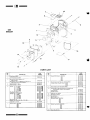
-ffiParts
Xl:Replacement
Section
I,
7-=_?
"/
68
B O I L ER
K
.///'
,{
\
6
14
--/.';
13
PARTSLIST
15
REF.
NO.
2
3
D
DESCRIPTION
PART
NUMSER
FrontSection,P-68-W(6813)
FrontS€ction.P-68'S,A or B-68-Wor S (6813)
316,60 . 2 1 6
316-60 .249
lntermediate
Section(6815)
Intermediat€
Sectionw/Lugs,A or B'868/968-Wor S (6816)
31 6-60
31 6-60
"T" BackSsction,Wide, P-68-S,A or B-68-Wor S (6818)
(€xcspt 868/968)
"T" Back Ssction,Wide w/Supply,A or B-868/968-W
or S
(6819)
thru P-768-W(6814)
Back Section,Narrow,P-268-W/P-468-W
Back Section,Wide, P-368-W(6817)
REF.
NO.
Reg Hex Nut,3/8
Washer, Pla n Type A A8
-222
-225
592-800-007
592-800-010
6
Ti€ Rod-1/2 x 81/2(P-268-W)
1/2x 10(P-368-W)
1/2x 111/2(P-468-W)
1/2x 141/2(P-568-W)
112x 17112(P-668-W\
112x 2O112(P-76A-W\
1/2x 10 (P-368-S,A or B-368-Wor S)
1i2x 13 (P-468-S,A or B-468-Wor S)
1/2x 161/4(P-568-S,A or B-568-Wor S)
1/2x 191/2(P-668-S,A or B-668-Wor S)
112x 2211a
(P-768-5,A or B-768-Wor S)
1/2x 111/2(A or B-868-Wor S)
1/2x l3 (A or B-868/968-W
or S)
112x 14112lAorB-968-Wor S)
1/2x 51/2(A or B-868/968-W
or S)
Reo. Hex Nut. 1/2-13
1/2HelicalSpring
Loclkwasher,
Tie Rod._q8 x 7112(P-268-W\
E8 x 9(P-368-W)
18 x 101h(P-468-W)
q8 x 131/2(P-568-W)
q8 x 161/4(P-668-W)
q8 x 191/2(P-768-W)
qB x 9 (P-368-S,A or B-368-w or S)
3/8 x 12 (P-468-S)
3/8 x 12112
(A or B-468-Wor S)
q8 x '15(P-568-S,A or B-568-Wor S)
E8 x 18 (P-668-S,A or B-668-Wor S)
3i8 x 21 (P-768-S,A or B-768-Wor S)
gB x 101/2(Aor 8-868W or S)
qs x !31/2(Aor 8-968W or S)
Es x 121/2(A or 8-868/968W or S)
560-234-4661
560-234-4671
560-234-4691
560-234-4714
560-234-4744
560-234-4781
560-234-4674
560-234-4681
560-234-4734
560-234-4761
560-234-4794
560-234-4691
560-234-4681
560-234-4714
560-234-4641
I
I
560-234-403t
560-234-4001
560-234-4071
560-234-4174
560-234-430t
560-234-435t
560-234-400t
560-234-408t
560-234-4124
560-234-4224
560-234-4331
560.234.4374
560-234-407I
560-234-4174
560-234-4124
I
T
438 x 1 00 x .083
Coge Seal (7'pef toinl)
591 -641,862
cleanout Plate
450,030-949
450-030-950
450-030-951
450-030-952
450-030,953
450-030,954
450-030955
8
cleanoutPlateGasket-268/368
468
568
668
768
868
968
591-22
591-22
591-22
591-22
591 22
591-22
591-22
I
Rectangular Heater Cover Plate (Steam)
Tankless Heater w/Gasket (Steam) 35-S-29
450-030-934
590-921-666
Rectangular Healer Cover Plate Gasket (Sleam)
590-317-579
RoundHeaterCoverPlale-q4" Opening(Water)
11/2o
" p e n i n g( s t e a m )
TanklessHeaterw/Gasket(water)-E-624
E-626
E-632
w/Gasket
62-E-2
Healer
Storaqe
592-243-217
592,243-216
590-921-670
590-921-675
s90-921-658
s90-921-665
316-601-234
316-601-219
316-601-228
ElaslomerSeal,6" (top)
Elastom€rSeal.3" (bottom)
PART
NUMBER
7
316-601-231
4
5
DESCRIPTION
10
1
14
15
17
I Can be purchasedat localsupplyhouse.
NOTE: Orderburnerpartsdirectlyfromburnermanufacturer.
'18
268/368
468
568
668
764
868
968
.260
.261
.262
.263
.264
.265
.266
RoundHeaterCoverPlateGasket(Wate0
s90-317-495
UniversalBurnerMountingPlateAss'y (includesburner
and insulation)
mountingplate,refractory,
FrontRefractory
Cerafeltlnsulation
343-500-540
s91-000-061
591-221-054
ObservationPortShutter
SecondaryAir Shutter
460-039-867
460-039-898
Rear Refraclory
Back RelractoryPin
RefractoryBlanket 268/368
468
568
668
768
868
968
59
59
59
59
59
59
59
59
59
ReturnPipe l\,lanifold
591-124-002
-2L-
-000-060
-000-054
-221-235
-221.230
-221-231
-221.232
-221-233
-221-234
.221-236
-um'--t2
' ;l
3ry_
68V
BO IL E R
i-
r
Oi i*'f '
'-:"
->-.=\>/
-:
'r
:_g,
t\
t
Jt,
-r)y
"",
5
l;
-16
t"t
a
\ .,,
13
?'
./
.6d
."'/
//E
,..f
15
PARTSLIST
REF.
NO.
DESCRIPTION
PAFT
NUMBER
FronlSection(6823)
316-60 1-237
2
Intermediate
Section(6825)
316,601 243
3
A or
BackSection,Wide, P-368V-W,
B-368V-W(6827)
BackSeclion,Narrow,P-468V-Wthru P768V-W,A or
B-468V-Wlhru A or B-768V-W(6824)
5
6
7
REF.
NO.
8
3 16 - 6 0 1 , 2 4 6
316-601-240
ElastomerSeal,6" (top)
Elastomerseal. 3" (bottom)
s92-800-007
592-800-010
Tie Rod-1/2 x r1/2(268V)
112x 0 (368V)
112x 11/2(468V)
112x 4112
(568V)
112x 7112
(668V)
112x r01/2
(768V)
R e g . H e x N u t , 1 it - 1 3
Lockwasher, l/2 telical Spring
'112(268V)
Tie Rod-98
x
q B x | (368v)
3/8 x 01/2(468V)
q8x
31/2(568V)
98x
61/4(668v)
g8x
91/2(768V)
Reg. Hex Nut, 3
Washer, Plain T / p eA q 8 - . 4 3 8 x1 . 0 0 x . 0 8 3
560-234-4661
560-234-4674
560-234-4691
560-234-4714
560-234-4744
560-234-4781
I
I
560-234-4031
560-234-4001
560-234-407I
560-234-4174
560-234-4301
560-234-4351
I
T
Cope Ssal (7' per joinl)
591-641-862
cleanoutPlate-268V/358V
468V
568V
668V
768V
450-030-960
450-030-961
450-030-962
450-030-963
450-030.964
13
14
lc
'16
17
'18
19
-22-
OESCRIPTION
PART
NUMBER
CleanoutPlateGaskel-268V/368V
468V
568V
668V
768V
591-22 .260
591-22 . 2 6 1
591,22 .262
591-22 263
591-22 264
FloundHeaterCoverPlale-314"Opening(Wator)
TanklessHeaterw/Gasket(Wateil-E-624
E-626
E-632
592,243217
590-921-670
590,921-675
-658
590-921
RoundHeaterCoverPlateGasket(Wale0
590-317-495
UniversalBurnerMountingPlaleAss'y (includesburner
mountingplate,refractory,and insulation)
Front Refractory
CerafeltInsulation
343-500,540
591-000-061
591-221-054
ObservationPon Shutter
SecondaryAir Shutter
460-039-867
460-039-898
Rear Relractory
Back RefractoryPin
RetractoryBlanket 268V/368V
468V
568V
668V
768V
59
59
59
59
59
59
59
VerticalFlueCollector268V/368V
468V
568V
668V
768V
450-020-100
450-020-1
01
450-020-102
450-020-1
03
450-020-104
ReturnPioe Manifold
591-124-002
-000-060
-000-054
-221"235
-221.230
-221-231
.22't-232
-221-233
U