1
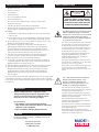
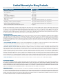
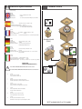
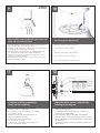
Installation and Operation Instructions
Before attempting to connect or operate this product, please
read these instructions completely.
FDW75
FusionDome Indoor Outdoor Wall or Pendant Mounted Camera Enclosure
™
FDW75C2N................IP Network Ready 7” Outdoor dome hsg w/wall mount, clear dome, with 24Vac input, Heater / Blower, fan an IP Network PTZ camera,
120 to 24Vac transformer
FDP75C2N.................IP Network Ready 7” Outdoor dome hsg w/pendant mount, clear dome, with 24Vac input, Heater / Blower, fan an IP Network PTZ camera,120 to 24Vac transformer
IFDW75CN.................IP Network Ready 7” Indoor dome hsg w/wall mount, clear dome, with 24Vac input, Heater / Blower, fan an IP Network PTZ camera,
120 to 24Vac transformer
IFDP75TN...................IP Network Ready 7” Indoor dome hsg w/pendant mount, clear dome, with 24Vac input, Heater / Blower, fan an IP Network PTZ camera,
120 to 24Vac transformer
FDW75C2NE..............IP Network Ready 7” Outdoor dome hsg w/wall mount, clear dome, with 24Vac input, Heater / Blower, fan an IP Network PTZ camera. (European Model)
FDP75C2NE..............IP Network Ready 7” Outdoor dome hsg w/pendant mount, clear dome, with 24Vac input, Heater / Blower, fan an IP Network PTZ camera. (European Model)
Pendant Mount
Moog Inc.
Sensor and Surveillance Systems
© 2013, Moog Inc. All Rights Reserved
3650 Woodhead Drive Northbrook, IL. USA 60062
+1.847.498.0700 Fax: +1.847.498.1258 www.moogS3.com
81-IN5358 013114
IMPORTANT SAFEGUARDS
1
Read these instructions.
2
Keep these instructions.
3
Heed all warnings
4
Follow all instructions.
5
Do not use this apparatus near water.
6
Clean only with damp cloth.
7
CAUTION
RISK OF ELECTRIC SHOCK
DO NOT OPEN
Do not block any of the ventilation openings. Install in accordance with the
manufacturers instructions.
8
9
SAFETY PRECAUTIONS
Cable Runs- All cable runs must be within permissible distance.
CAUTION: TO REDUCE THE RISK OF
ELECTRIC SHOCK, DO NOT REMOVE
COVER ( OR BACK). NO USER- SERVICEABLE PARTS INSIDE. REFER SEVICING
TO QUALIFIED SERVICE PERSONNEL.
Mounting - This unit must be properly and securely mounted to a supporting
structure capable of sustaining the weight of the unit.
Accordingly:
a. This installation should be made by a qualified service person and should conform
to all local codes.
b. Care should be exercised to select suitable hardware to install the unit, taking into
account both the composition of the mounting surface and the weight of the unit.
10 Do not install near any heat sources such as radiators, heat registers, stoves, or other
apparatus ( including amplifiers) that produce heat.
11 Do not defeat the safety purpose of the polarized or grounding-type plug. A
polarized plug has two blades with one wider than the other. A grounding type
plug has two blades and a third grounding prong. The wide blade or the third
prong are provided for your safety. When the provided plug does not fit into your
outlet, consult an electrician for replacement of the obsolete outlet.
12 Protect the power cord from being walked on or pinched particularly at plugs,
convenience receptacles, and the point where they exit from the apparatus.
13 Only use attachment/ accessories specified by the manufacturer.
14 Use only with a cart, stand, tripod, bracket, or table specified by the manufacturer,
or sold with the apparatus. When a cart is used, use caution when moving the cart/
apparatus combination to avoid injury from tip-over.
15 Unplug this apparatus during lighting storms or when unused for long periods of time.
16 Refer all servicing to qualified service personnel. Servicing is required when the
apparatus has been damaged in any way, such as power-supply cord or plug is
damaged, liquid has been spilled of objects have fallen into the apparatus, the
The lightning flash with an arrowhead symbol,
within an equilateral triangle, is intended to
alert the user to the presence of non-insulated
“dangerous voltage” within the product’s
enclosure that may be of sufficient magnitude
to constitute a risk to persons.
Este símbolo se piensa para alertar al usuario a la presencia
del “voltaje peligroso no-aisIado” dentro del recinto de los
productos que puede ser un riesgo de choque eléctrico.
Ce symbole est prévu pour alerter I’utilisateur à la presence
“de la tension dangereuse” non-isolée dans la clôture de
produits qui peut être un risque de choc électrique.
Dieses Symbol soll den Benutzer zum Vorhandensein der
nicht-lsolier “Gefährdungsspannung” innerhalb der
Produkteinschließung alarmieren die eine Gefahr des
elektrischen Schlages sein kann.
Este símbolo é pretendido alertar o usuário à presença “di
tensão perigosa non-isolada” dentro do cerco dos produtos
que pode ser um risco de choque elétrico.
Questo simbolo è inteso per avvertire I’utente alla presenza
“di tensione pericolosa” non-isolata all’interno della
recinzione dei prodotti che può essere un rischio di scossa
elettrica.
apparatus has been exposed to rain or moisture, does not operate normally, or
has been dropped.
Be sure to periodically examine the unit and the supporting structure to make sure that the integrity
of the installation is intact. Failure to comply with the foregoing could result in the unit separating
from the support structure and falling, with resultant damages or injury to anyone or anything struck
by the falling unit.
UNPACKING
Unpack carefully. Electronic components can be
damaged if improperly handled or dropped. If an item
appears to have been damaged in shipment, replace
it properly in its carton and notify the shipper.
Be sure to save:
1 The shipping carton and packaging material.
They are the safest material in which to make future
shipments of the equipment.
2 These Installation and Operating Instructions.
SERVICE
If technical support or service is needed, contact us at
the following number:
TECHNICAL SUPPORT
AVAILABLE 24 HOURS
1 - 800 - 554 -1124
The exclamation point within an equilateral
triangle is intended to alert the user to
presence of important operating and
maintenance (servicing) instructions in the
literature accompanying the appliance.
Este símbolo del punto del exclamation se piensa para
alertar al usuario a la presencia de instrucciones importantes
en la literatura que acompaña la aplicación.
Ce symbole de point d’exclamation est prévu pour alerter
l’utilisateur à la presence des instructions importantes dans
la littérature accompagnant l’appareil.
Dieses Ausruf Punktsymbol soll den Benutzer zum
Vorhandensein de wichtigen Anweisungen in der Literatur
alarmieren, die das Gerät begleitet.
Este símbolo do ponto do exclamation é pretendido alertar o
usuário à presença de instruções importantes na literatura
que acompanha o dispositivo.
Questo simbolo del punto del exclamaton è inteso per
avvertire l’utente alla presenza delle istruzioni importanti nella
letteratura che accompagna l'apparecchio.
MADEIN
USA
BUY AMERICA COMPLIANT • COUNTRY OF ORIGIN U.S.A.
Product Warranty Registration
Register Your Products Online
www.moogS3.com/technical-support/product-registration
Moog values your patronage. We are solely committed to providing you with the highest quality products and
superior customer service. With 3-Year and 5-Year warranties (depending on the product purchased) we stand
behind every product we sell.
See full warranty details at www.moogS3.com/technical-support/warranty-plan/
:
• Simple and Trouble-Free RMA process
• Product / software updates
• Special promotions
• Eliminate the need to archive purchase documents such as receipts, purchase orders, etc.
Limited Warranty for Moog Products
Moog - Decatur Operations, subsequently referred to as “Manufacturer,” warrants these products to be free from defects in material or workmanship as follows:
PRODUCT CATEGORY
PARTS \ LABOR
All Enclosures and Electronics
Five (5) Years
Accessory Brackets
Five (5) Years
Controllers
Three (3) Years
Power Supplies / IR Illuminators
Three (3) Years
Poles / PolEvators / CamEvator
Three (3) Years
Warrior Series™ / Q-View™
Three (3) Years
™
Three (3) Years 6 months if used in auto scan / tour operation
SView Series
™
DeputyDome , NiteTrac , Igloo Dome, PurgeDome
Three (3) Years 6 months if used in auto scan / tour operation
EXO Series™ Dome and Fixed Camera Systems*
Three (3) Years 6 months if used in auto scan / tour operation
EXO Series™ GeminEye Visible and Thermal Camera Systems
One (1) Year
™
™
™
During the labor warranty period, to repair the Product, Purchaser will either return the defective product, freight prepaid, or deliver it to Manufacturer at Moog Decatur
Operations, 2525 Park Central Boulevard, Decatur, Georgia, 30035. The Product to be repaired is to be returned in either its original carton or a similar package affording
an equal degree of protection with a RMA # (Return Materials Authorization number) displayed on the outer box or packing slip. To obtain a RMA# you must contact our
Technical Support Team at 800.554.1124, extension 101. Manufacturer will return the repaired product freight prepaid to Purchaser. Manufacturer is not obligated to
provide Purchaser with a substitute unit during the warranty period or at any time. After the applicable warranty period, Purchaser must pay all labor and/or parts charges.
The limited warranty stated in these product instructions is subject to all of the following terms and conditions.
TERMS AND CONDITIONS
1. NOTIFICATION OF CLAIMS: WARRANTY SERVICE: If Purchaser believes that the Product is defective in material or workmanship, then written notice with an explanation
of the claim shall be given promptly by Purchaser to Manufacturer. All claims for warranty service must be made within the warranty period. If after investigation,
Manufacturer determines the reported problem was not covered by the warranty, Purchaser shall pay Manufacturer for the cost of investigating the problem at its then
prevailing per incident billable rate. No repair or replacement of any Product or part thereof shall extend the warranty period of the entire Product. The specific warranty on
the repaired part only shall be in effect for a period of ninety (90) days following the repair or replacement of that part or the remaining period of the Product parts warranty,
whichever is greater.
2. EXCLUSIVE REMEDY: ACCEPTANCE: Purchaser’s exclusive remedy and Manufacturer’s sole obligation is to supply (or pay for) all labor necessary to repair any Product
found to be defective within the warranty period and to supply, at no extra charge, new or rebuilt replacements for defective parts.
3. EXCEPTIONS TO LIMITED WARRANTY: Manufacturer shall have no liability or obligation to Purchaser with respect to any Product requiring service during the warranty
period which is subjected to any of the following: abuse, improper use, negligence, accident, or acts of God (i.e., hurricanes, earthquakes), modification, failure of the
end-user to follow the directions outlined in the product instructions, failure of the end-user to follow the maintenance procedures recommended by the International Security
Industry Organization, written in product instructions, or recommended in the service manual for the Product. Furthermore, Manufacturer shall have no liability where a
schedule is specified for regular replacement or maintenance or cleaning of certain parts (based on usage) and the end-user has failed to follow such schedule; attempted
repair by non-qualified personnel; operation of the Product outside of the published environmental and electrical parameters, or if such Product’s original identification
(trademark, serial number) markings have been defaced, altered, or removed. Manufacturer excludes from warranty coverage Products sold AS IS and/or WITH ALL FAULTS
and excludes used Products which have not been sold by Manufacturer to the Purchaser. All software and accompanying documentation furnished with, or as part of the
Product is furnished “AS IS” (i.e., without any warranty of any kind), except where expressly provided otherwise in any documentation or license agreement furnished with
the Product. ANY COST ASSOCIATED WITH REMOVAL OF DEFECTIVE PRODUCT AND INSTALLATION OF REPLACEMENT PRODUCT IS NOT INCLUDED IN THIS WARRANTY.
4. PROOF OF PURCHASE: The Purchaser’s dated bill of sale must be retained as evidence of the date of purchase and to establish warranty eligibility.
DISCLAIMER OF WARRANTY
EXCEPT FOR THE FOREGOING WARRANTIES, MANUFACTURER HEREBY DISCLAIMS AND EXCLUDES ALL OTHER WARRANTIES, EXPRESS OR IMPLIED, INCLUDING, BUT
NOT LIMITED TO ANY AND/OR ALL IMPLIED WARRANTIES OF MERCHANTABILITY, FITNESS FOR A PARTICULAR PURPOSE AND/OR ANY WARRANTY WITH REGARD TO ANY
CLAIM OF INFRINGEMENT THAT MAY BE PROVIDED IN SECTION 2-312(3) OF THE UNIFORM COMMERCIAL CODE AND/OR IN ANY OTHER COMPARABLE STATE STATUTE.
MANUFACTURER HEREBY DISCLAIMS ANY REPRESENTATIONS OR WARRANTY THAT THE PRODUCT IS COMPATIBLE WITH ANY COMBINATION OF NON-MANUFACTURER
PRODUCTS OR NON-MANUFACTURER RECOMMENDED PRODUCTS PURCHASER MAY CHOOSE TO CONNECT TO THE PRODUCT.
LIMITATION OF LIABILITY
THE LIABILITY OF Manufacturer, IF ANY, AND PURCHASER’S SOLE AND EXCLUSIVE REMEDY FOR DAMAGES FOR ANY CLAIM OF ANY KIND WHATSOEVER, REGARDLESS
OF THE LEGAL THEORY AND WHETHER ARISING IN TORT OR CONTRACT, SHALL NOT BE GREATER THAN THE ACTUAL PURCHASE PRICE OF THE PRODUCT WITH RESPECT
TO WHICH SUCH CLAIM IS MADE. IN NO EVENT SHALL MANUFACTURER BE LIABLE TO PURCHASER FOR ANY SPECIAL, INDIRECT, INCIDENTAL, OR CONSEQUENTIAL
DAMAGES OF ANY KIND INCLUDING, BUT NOT LIMITED TO, COMPENSATION, REPLACEMENT LABOR COSTS, REIMBURSEMENT, OR DAMAGES ON ACCOUNT OF THE LOSS
OF PRESENT OR PROSPECTIVE PROFITS OR FOR ANY OTHER REASON WHATSOEVER.
* NOTE
Moog will repair or replace, at its option, any equipment which is damaged by transient voltage surge/spike or lightning strike (an “Occurrence”), while properly connected
to wired AC power line with protective ground. Any repair or modification of the equipment done by someone other than Moog voids the warranty.
Form 500-911 081913
!
Electrical Specifications
Power 24VAC
Class 2 Only
24 VAC
26 Watts
Accessories:
Camera Power:
Tools Required:
Contents of Box
FDW75
Heater: 25 Watts, Blower: 1 Watt
28 Watts
.100” Flat Head Screwdriver Phillips Head Screwdriver
English
Español
24 VAC
26 vatios
Accesorios:
Calentador: 25 Vatios, Soplador: 1 vatio
Energía De la Cámara fotográfica: 28 vatios
Las Herramientas Requirieron: Destornillador Principal Plano Del
100". Destornillador Principal Phillips.
24 VCA
26 watts
Accessoires :
Réchauffeur : 25 Watts, Ventilateur : 1 watt
Puissance D'Appareil-photo :
28 watts
Les Outils Ont exigé :
Tournevis Principal Plat De 100. Tournevis Principal Phillips.
Français
Deutsch
24 VAC
26 Watt
Zusatzgeräte:
Heizung: 25 Watt, Gebläse: 1 Watt.
Kamera-Energie:
28 Watt
Werkzeuge Erforderten: 100"Flacher Hauptschraubenzieher.
Kreuzkopfhauptschraubenzieher.
Pendent Model
(ONLY)
24 VAC
26 watts
Acessórios:
Calefator: 25 Watts, Ventilador: 1 watt.
Poder Da Câmera:
28 watts
Ferramentas Requeridas: Chave de fenda Principal Lisa Do 100". Chave de fenda
Principal Phillips.
Portuguese
A
24 VCA.
26 watt
Accessori: Riscaldatore: 25 Watt, Ventilatore: 1 watt.
Alimentazione Della Macchina fotografica:
28 watt
Gli Attrezzi Hanno richiesto: Cacciavite Capo Piano Del 100". Cacciavite Capo "phillips".
Italiano
B
IFDP75CFN
FDW75CFN (INDOOR ONLY)
!
Indoor Models IFDP75CN/ IFDP75CN Include NO Power Accessories
*
International Models FDW75C2NE/ FDP75C2NE Include NO Power Transformer
24 VAC
No power options provided.
Power required for camera only.
24 VAC
Ningunas opciones de la energía proporcionaron.
Energía requerida para la cámara fotográfica solamente.
24 VCA
Option de puissance n'a pas fourni.
Puissance requise pour l'appareil-photo seulement.
24 VAC
Keine Energie Wahlen stellten zur Verfügung.
Energie erfordert für nur Kamera.
24 VAC
Nenhumas opções do poder fornecidas.
Poder requerido para a câmera somente.
24 VAC
Nessun'opzione di alimentazione ha fornito.
Alimentazione richiesta per la macchina fotografica soltanto.
* NOT included with E or 12V models
1
WALL MOUNTING
2
4”-5”
Bracket is designed for 45° conduit fitting (If using the
conduit). Run wire into bracket, secure to wall.
• El soporte se diseña para la guarnición del conducto 45° (si usa el
conducto). Funcione con el alambre en el soporte seguro para
emparedar.
• La parenthèse est conçue pour l'ajustage de précision du conduit 45° (si
à l'aide du conduit). Courez le fil dans la parenthèse bloquée pour murer.
• Haltewinkel ist für Befestigung des Rohres 45° bestimmt (wenn das Rohr
verwendet wird). Lassen Sie Draht in den Haltewinkel laufen, der, um zu
ummauern sicher ist.
• O suporte é projetado para o encaixe da canalização 45° (se usando a
canalização). Funcione o fio no suporte seguro para murar.
• La staffa è progettata per il montaggio del condotto 45° (se per mezzo
del condotto). Faccia funzionare il legare nella staffa sicura per murare.
3
Secure lanyard to lanyard clip.
Trim incoming control & power wires to 4”- 5”,
for either wall or pendent bracket.
• & entrante del control del ajuste; accione los alambres a 4” - 5”, para
la pared o el soporte pendiente.
• & entrant de commande d'équilibre ; actionnez les fils à 4 » - 5 », pour
le mur ou la parenthèse en suspens.
• Ankommendes & Steuer der Ordnung; antreiben Sie Drähte bis 4“ - 5“,
entweder für Wand oder pendent Haltewinkel r.
• & entrante do controle da guarnição; pnha fios a 4” - 5”, para a
parede ou o suporte pendent.
• & ricevuto di controllo della disposizione; alimenti i legare a 4„ - 5„,
per la parete o la staffa pendent.
4
Complete ALL wiring connections.
• Asegure el acollador al clip del acollador.
• Termine TODAS LAS conexiones del cableado.
• Fixez la lanière à l'agrafe de lanière.
• Accomplissez TOUS LES raccordements de câblage.
• Befestigen Sie Abzuglinie an Abzuglinieclip.
• Schließen Sie ALLE Verdrahtungsanschlüsse ab.
• Fixe o colhedor ao grampo do colhedor.
• Termine TODAS AS conexões da fiação.
• Assicuri la cordicella alla clip della cordicella.
• Completi TUTTI I collegamenti dei collegamenti.
5
WALL MOUNTING
6
!
26 Watts
C
Important
Gasket
Must be in
place
COAX
(coax wire not supplied)
Wiring the dome can be completed by
referring to the diagram.
• Atar con alambre la bóveda puede ser terminada
refiriendo al diagrama.
• Le câblage du dôme peut être accompli en se
rapportant au diagramme.
• Das Verdrahten der Haube kann durchgeführt
werden, indem man auf das Diagramm sich bezieht.
• Wiring a abóbada pode ser terminado consultando
ao diagrama.
• Legare la cupola può essere completato riferendosi
allo schema.
7
To lock, turn clockwise.
Align large arrows.
• Alinee las flechas grandes.
• Alignez les grandes flèches.
• Richten Sie große Pfeile aus.
• Alinhe grandes setas.
• Allini le grandi frecce.
8
Secure with ¼” Allen wrench.
• Para trabarse, dar vuelta a la derecha.
• Asegure con la llave Allen del ¼”.
• Pour fermer à clef, tourner dans le sens des aiguilles d'une montre.
• Fixez clé Allen avec de ¼ ».
• Zu sich verriegeln, nach rechts drehen.
• Sichern Sie mit ¼“ Inbusschlüssel.
• Para travar, para girar no sentido horário.
• Fixe com chave Allen do ¼ de”.
• Per per chiudere, girare in senso orario.
• Fissi con chiave di Allen del ¼„.
9
FOR PENDENT/
WALL MOUNTING
10
4”-5”
Trim incoming control and power wires to 4-5” for
either wall or pendent bracket.
• Ajuste los alambres entrantes del control y de la energía a
4-5” para la pared o el soporte pendiente.
• Équilibrez les fils entrants de commande et de puissance à 4-5
» pour le mur ou la parenthèse en suspens.
• Trimmen Sie ankommende Steuer- und Energiendrähte bis
4-5“ entweder für Wand oder pendent Haltewinkel.
• Apare fios entrantes do controle e do poder a 4-5” para a
parede ou o suporte pendent.
• Assetti i legare ricevuti di potere e di controllo a 4-5„ per la
parete o la staffa pendent.
11
Secure lanyard to lanyard clip.
• Asegure el acollador al clip del acollador.
• Fixez la lanière à l'agrafe de lanière.
• Befestigen Sie Abzuglinie an Abzuglinieclip.
• Fixe o colhedor ao grampo do colhedor.
• Assicuri la cordicella alla clip della cordicella.
12
26 Watts
C
COAX
(coax wire not supplied)
Complete all wiring connections
(coax wire not supplied).
• Termine todas las conexiones del cableado
(alambre coaxil no suministrado).
• Accomplissez tous les raccordements de câblage
(fil coaxial non fourni).
• Schließen Sie alle Verdrahtungsanschlüsse ab
(koaxialer Draht nicht geliefert).
• Termine todas as conexões da fiação
(fio co-axial não fornecido).
• Completi tutti i collegamenti dei collegamenti
(legare coassiale non fornito).
Wiring the dome can be completed by
referring to the diagram.
• Atar con alambre la bóveda puede ser terminada
refiriendo al diagrama.
• Le câblage du dôme peut être accompli en se
rapportant au diagramme.
• Das Verdrahten der Haube kann durchgeführt
werden, indem man auf das Diagramm sich bezieht.
• Wiring a abóbada pode ser terminado consultando
ao diagrama.
• Legare la cupola può essere completato riferendosi
allo schema.
13
14
Important
Gasket
Must be in
place
!
Align large arrows.
To lock, turn clockwise.
• Alinee las flechas grandes.
• Para trabarse, dar vuelta a la derecha.
• Alignez les grandes flèches.
• Pour fermer à clef, tourner dans le sens des aiguilles d'une
montre.
• Richten Sie große Pfeile aus.
• Alinhe grandes setas.
• Allini le grandi frecce.
15
Secure with ¼” Allen wrench.
• Asegure con la llave Allen del ¼”.
• Fixez clé Allen avec de ¼”.
• Sichern Sie mit ¼“ Inbusschlüssel.
• Fixe com chave Allen do ¼ de”.
• Fissi con chiave di Allen del ¼”.
• Zu sich verriegeln, nach rechts drehen.
• Para travar, para girar no sentido horário.
• Per per chiudere, girare in senso orario.
16
!
To loosen - unscrew bolts ½” turn counter
clockwise.
• Para aflojar - desatornille a la derecha contrario de la vuelta
del ½ de los pernos”.
• Pour se desserrer - dans le sens des aiguilles d'une montre de
tour dévissez de boulons ½ » contre-.
• Um sich zu lösen - schrauben Sie Schraubbolzen ½“
Umdrehungs-Gegenrechtses herum ab.
• Para afrouxar - desaparafuse sentido horário contrário volta
do ½ dos parafusos da”.
• Per allentare - sviti in senso orario di girata del ½ dei bulloni„
contro.
17
RJ45
24VAC
1
2
3
4
Camera
Camera
Heater/Blower
Heater/Blower
POWER
Red
Orange
Yellow
Green
28 Watts
26 Watts
1/0
1
2
3
4
Alarm 1
Alarm 2
Alarm 3
Common
Blue
Violet
Gray
White
BNC
Make the appropriate male and female connections. Indoor model does not include pre-run cables.
• Haga las conexiones masculinas y femeninas apropiadas. El modelo de interior no incluye pre-funciona los cables.
• Établissez les rapports masculins et femelles appropriés. Le modèle d'intérieur n'inclut pas pré-courent des câbles.
• Stellen Sie die passenden männlichen und weiblichen Beziehungen her. Innenmodell schließt nicht vor-laufen lassen Kabel
ein.
• Faça as conexões masculinas e fêmeas apropriadas. O modelo indoor não inclui pre-funciona cabos.
• Faccia i collegamenti maschii e femminili adatti. Il modello dell'interno non include pre-fa funzionare i cavi.
18
19
12
Green
Yellow
Orange
Accessory
Power
,5
22
,75
20
1,0
18
1,5
16
2,5
14
4
12
6
10
MM2
AWG
Camera
Power
Red
Camera = red & orange wires to terminal
Heater/Blower = yellow & green wires to terminal.
• Cámara fotográfica = alambres rojos y anaranjados al
terminal Heater/Blower = alambres del amarillo y del verde
al terminal.
• Appareil-photo = fils rouges et oranges à la borne
Heater/Blower = fils de jaune et de vert à la borne.
• Kamera = rote u. orange Leitungen zum Anschluß
Heater/Blower = Gelb- u. Grünleitungen zum Anschluß.
• Câmera = fios vermelhos & alaranjados ao terminal
Heater/Blower = fios do amarelo & do verde ao terminal.
• Macchina fotografica = legare rossi & arancioni al terminale
Heater/Blower = legare di verde & di colore giallo
al terminale.
These
are recommended
distances
The
beam
angle may bemaximum
adjusted on
the
for
24VAC
with
a
10%
voltage
drop.
bottom of the unit.
• Éstos se recomiendan las distancias máximas para
24VAC con una gota del voltage del 10%.
• Ceux-ci sont recommandés des distances maximum
pour 24VAC avec une chute de tension de 10%.
• Diese werden maximale Abstände für 24VAC mit
einem 10% Spannungsabfall empfohlen.
• Estes são recomendados distâncias máximas para
24VAC com uma queda de tensão de 10%.
• Questi sono suggeriti distanze massime per 24VAC
con una differenza de potenziale di 10%.
12Vdc Cameras
20
12Vdc
Power
Supply
21
12Vdc
Out
12Vdc power supply for camera.
12Vdc Plug
If using 12Vdc connect plug to camera.
• Fuente de alimentación de 12 Vcc para la cámara.
• Si se utiliza 12Vdc conecte el enchufe a la cámara.
• Alimentation 12Vcc pour la caméra.
• Si vous utilisez 12Vdc branchez la fiche à la caméra.
• 12Vdc Stromversorgung für die Kamera.
• Bei Verwendung von 12 V DC Stecker auf Kamera.
• Fonte de alimentação 12Vcc para a câmera.
• Se estiver usando 12Vdc conectar plugue para a câmera.
• Alimentazione 12Vdc per telecamera.
• Se si utilizza 12Vdc collegare la presa alla telecamera.
24Vac Cameras
22
23
24Vac
If using 24Vac camera disconnect 24Vac
input to power supply and connect to camera.
• Si se utiliza la cámara 24Vac desconectar la entrada de 24
VCA a la fuente de alimentación y conectar a la cámara.
• Si vous utilisez la caméra 24Vac déconnecter entrée
24Vac à l'alimentation et connecter à la caméra.
• Bei Verwendung von 24Vac Kamera trennen 24Vac
Eingang zu Hilfsenergie und eine Verbindung zu Kamera.
• Se estiver usando câmera 24Vac desconectar entrada
24Vac a fonte de alimentação e ligar a câmera.
• Se si utilizza fotocamera 24Vac scollegare ingresso
24Vac alla rete elettrica e collegare alla fotocamera.
Electrical connection to 24Vac camera/pan tilt is
shown above. See camera mount insert for
mechanical connections.
• La conexión eléctrica a 24 V CA / cámara Pan Tilt se muestra arriba.
Vea el inserto de la cámara de conexiones mecánicas.
• Le raccordement électrique à 24Vac caméra / Pan Tilt est indiqué
ci-dessus. Voir montage de la caméra d'insertion pour des
connexions mécaniques.
• Elektrischer Anschluss an 24Vac Kamera / Pan Tilt ist oben abgebildet.
Siehe Kamerahalter Einsatz für mechanische Verbindungen.
• Conexão elétrica para 24Vac inclinação da câmera / pan é mostrada
acima. Veja Acessório de câmera de montagem para conexões mecânicas.
• Il collegamento elettrico alla fotocamera 24Vac / pan tilt è indicato sopra.
Vedi Innesto supporto per connessioni meccaniche.
24
25
Before
Tab
After
Loop the lanyard around the tab inside the
housing.
Align the arrows on the outside of the dome
and lock.
• Coloque el acollador alrededor de la lengüeta
dentro de la cubierta.
• Faites une boucle la lanière autour de l'étiquette à
l'intérieur du logement.
• Schlingen Sie die Abzuglinie um den Vorsprung
innerhalb des Gehäuses.
• Dê laços no colhedor em torno da aba dentro da
carcaça.
• Colleghi la cordicella in circuito intorno alla
linguetta all'interno dell'alloggiamento.
• Alinee las flechas en el exterior de la bóveda y
trábese.
• Alignez les flèches sur l'extérieur du dôme et
fermez à clef.
• Richten Sie die Pfeile auf der Außenseite der
Haube aus und verriegeln Sie sich.
• Alinhe as setas na parte externa da abóbada e
trave-as.
• Allinei le frecce sulla parte esterna della cupola e
blocchi.
26
27
Fasten down the dome with a Phillips
screwdriver.
Wipe the dome clean.
• Sujete abajo de la bóveda con un destornillador
Phillips.
• Attachez en bas du dôme avec un tournevis
Phillips.
• Befestigen Sie sich hinunter die Haube mit einem
Kreuzkopfschraubenzieher.
• Prenda abaixo a abóbada com uma chave de
fenda Phillips.
• Fissisi giù la cupola con un cacciavite "phillips".
• Limpie la bóveda limpia.
• Essuyez le dôme.
• Wischen Sie die Haube sauber ab.
• Limpe a abóbada limpa.
• Asciughi la cupola.
PB24 Addendum
Additional wires are provided to run power to PB24. Use with connector supplied. Run RJ45 connector
through PB24, wall mount, and connect lead from housing.
• Los alambres adicionales se proporcionan a la energía funcionada con a PB24. El uso con el conectador proveyó.
Funcione con el conectador RJ45 con PB24, emparede el montaje, y conecte el plomo de la cubierta.
• Des fils additionnels sont fournis à la puissance courue à PB24. L'utilisation avec le connecteur a fourni. Courez le
connecteur RJ45 par PB24, murez le bâti, et reliez le fil du logement.
• Zusätzliche Drähte zur Verfügung gestellt zu laufen gelassener Energie zu PB24. Gebrauch mit Verbindungsstück lieferte.
Laufen lassen Sie Verbindungsstück RJ45 durch PB24, ummauern Sie Einfassung und anschließen Sie Blei vom Gehäuse n.
• Os fios adicionais são fornecidos ao poder funcionado a PB24. O uso com conector forneceu. Funcione o conector RJ45
com PB24, mure a montagem, e conecte a ligação da carcaça.
• I legare supplementari sono forniti a potere funzionato a PB24. L'uso con il connettore ha fornito. Faccia funzionare il
connettore RJ45 con PB24, muri il supporto e colleghi il cavo da alloggiamento.
Replacement Parts List
FDW75
14
15
16
13
17
12
11
10
9
8
18
7
5
6
4
3
1
2
1
1A
2
3
4
5
5A
6
7
8
8A
9
10
11
12
13
14
15
16
N/S
N/S
N/S
PART NUMBER
RCFD7
RCFD8
RPFD7501
RPFD703
RPNET02
RPFD072
RPFD072/12
RPFD080
RP3510
RP76FD7PB2
RP70FP7PB12
RPFD040
RPFD2612
RPFD3245
RPGK3356
RP3458
RP3551
RP3606
RP3719
RP46PKH2012
RPPKE1100
RPTRAN02
DESCRIPTION
CLEAR REPLACEMENT CAPSULE
TINTED REPLACEMENT CAPSULE
LOWER TRIM RING
DOME CLAMPING RING
NETWORK HGS POWER SUPPLY
24V HEATER
12V HEATER (12VDC MODELS ONLY)
BLOWER
CAMERA BRACKET
CONNECTION PCB(24VAC)
CONNECTION PCB (12VDC)
HOUSING TOP
HOUSING TOP GASKET
WALL/PENDENT ADAPTER
WALL/PENDENT GASKET
LANYARD SET
WM11 WALL MOUNT
PENDENT MOUNT BRACKET
1 1/2 FEMALE /FEMALE COUPLING
BRACKET PACKET ASSEMBLY
ELECTRICAL PACKET ASSEMBLY
110 TO 24VAC WALL TRANSFORMER