1
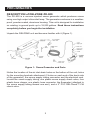
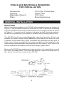
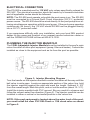
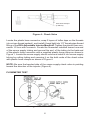
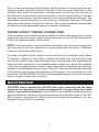
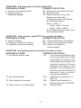
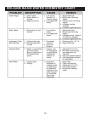
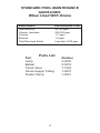
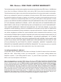
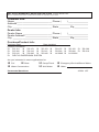
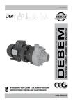
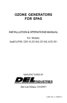
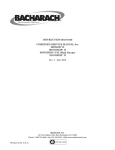
INSTALLATION & OPERATIONS MANUAL FOR ZO-900 OZONE SYSTEM FOR IN-GROUND POOLS UP TO 18,000 GALLONS MANUFACTURED BY 3428 Bullock Lane San Luis Obispo, CA 93401 800-676-1335 4-0449 Rev. A.- 052605 Copyright © 2005 DEL Ozone, Inc. IMPORTANT SAFETY INSTRUCTIONS When installing and using DELZONE® Model ZO-900, basic safety precautions should always be followed. Be sure all the electrical power is shut OFF at the main circuit breaker before installing the ZO-900. 1. READ AND FOLLOW ALL INSTRUCTIONS. 2. All permanent electrical connections should be made by a qualified electrician. 3. For cord- and plug-connected units, connect to a grounded, grounding type receptacle only. If the ZO-900 electrical connection is to be attached to the pool controls, be sure the pool controls are protected by a Ground Fault Circuit Interrupter (G.F.C.I.). If the ZO-900 is connected to an independent electrical supply, then a G.F.C.I. must be installed between the ZO-900 and the electrical supply. 4. Do not bury cord. 5. WARNING: To reduce the risk of electric shock, replace damaged cord immediately. 6. A pressure wire connector is provided on the outside of the unit to permit connection to a minimum No. 8 AWG (8.4 mm ) solid bonding conductor between this point and any metal equipment, metal enclosures of electrical equipment, metal water pipe, or conduit within five (5) feet (1.5m) of the unit as needed to comply with local requirements. lnstall at least 5 feet (1.5m) from the inside wall of the pool and one foot above the maximum water level to prevent water from contacting electrical equipment using non-metallic tubing. This product is not intended for use under the skirt of a spa or hot tub. 7. The ZO-900 must be installed in an outdoor location, or indoors in a forced air ventilated room. Install so that the orientation is as shown in Figure 1. This will provide water drainage of the generator to protect electrical components. 8. The ZO-900 lamp emits ultraviolet light which is harmful to your eyes and skin if exposed. Always have the electrical power OFF when removing the endcap from the ZO-900 and exposing the lamp. 9. Mount the ZO-900 so that it is inaccessible to anyone in the pool. Never attempt any servicing while unit is wet. 10. Follow all applicable electrical codes. 11. Plastic ozone supply tubing is supplied with the ZO-900. Never replace this tubing with metal tubing. 12. For wall mounting indoors/protected areas only. 13. Warning: Short term inhalation of high concentrations of ozone and long term inhalation of low concentrations of ozone can cause serious harmful physiological effects. Do not inhale ozone gas produced by this device. 14. SAVE THESE INSTRUCTIONS. 2 1 TABLE OF CONTENTS TABLE OF CONTENTS SAFETY INSTRUCTIONS...................................................1 TABLE OF CONTENTS.......................................................2 PRELIMINARIES.................................................................3 Description of DELZONE ZO-900 ........................................................................ 3 Tools and Materials................................................................ 4 GENERAL INSTALLATION .................................................4 Mounting................................................................................ 4 Electrical Connection............................................................. 5 Plumbing the Injector Manifold .............................................. 5 Flowmeter Test ...................................................................... 6 Ozone Supply Tubing Connection ......................................... 7 MAINTENANCE ..................................................................7 The ZO-900 Lamp ..........................................................8 Changing the ZO-900 Lamp ...........................................8 Cabinet Cleaning ...........................................................8 TROUBLE SHOOTING .......................................................8 BASIC WATER CHEMISTRY CHART...............................10 WARRANTY ......................................................................12 2 PRELIMINARIES DESCRIPTION of DELZONE ZO-900 The ZO-900 is a vacuum-injected ozone generator which produces ozone using one high output ultraviolet lamp. The generator enclosure is a weatherproof, powder coated, aluminum housing. This unit is designed for installation on existing in-ground pools up to 18,000 gallons. Read these instructions completely before you begin the installation. Unpack the DELZONE unit and become familiar with it (Figure 1). Figure 1: Ozone Generator and Parts Notice the location of the air inlet-drain holes on the bottom of the unit, holes for the mounting brackets attachment (2 holes on each end of the back side of the generator), the ozone supply tubing connector, and the electrical cord. Locate the ozone supply tubing, one plastic ozone supply check valve, four plastic hose clamps, one plastic hose connector, the flowmeter (attached to the ozone supply tubing toward one end), and a 2" PVC DELCheck™1/3# check valve. 3 TOOLS AND MATERIALS REQUIRED FOR INSTALLATION Screwdriver Scissors Adjustable Wrench Pliers PVC Pipe Cutters/Saw Teflon Tape PVC Glue Mounting Screws GENERAL INSTALLATION MOUNTING Attach mounting brackets to the ZO-900 with provided screws as shown on Figure 1. Find a suitable location to install the ZO-900. It cannot be accessible to anyone inside the pool and must be mounted in an upright position as shown in Figure 2. A second set of brackets (indicated as wall mounting brackets, located in the parts bag) is provided for optional wall mounting indoors only. The ZO-900 should be mounted above the water line if possible. If this is not possible, the ozone supply tubing must be routed above the water line with a Hartford Loop (water trap; Figure 2) between the generator and the pool. In either case, the ozone supply check valve provided must be installed in the ozone supply tubing between the generator and the injector. See Figure 4 for further installation information on the ozone supply check valve. Because the ZO-900 generates heat during operation, it is a good idea to mount the unit in a shaded area. If the mounting area is subject to blowing dust or dirt, shelter should be provided for the ZO-900. Figure 2: Installation Diagram 4 ELECTRICAL CONNECTION The ZO-900 is manufactured for 110 VAC only unless specifically ordered for 220 VAC. The electrical connection should be made by a licensed electrician and all applicable codes should be followed. NOTE: The ZO-900 must operate only while the pool pump is on. The ZO-900 must be connected to a Ground Fault Circuit Interrupter (G.F.C.I.) protected power source. The ZO-900 should be wired directly to the pool pump timer allowing simultaneous operation with the pool pump. If the pool pump operates continuously (24 hours), the 110 VAC model ZO-900 can be plugged directly into a G.F.C.I. protected outlet. If you experience difficulty with your installation, ask your local DEL product dealer for the name and location of our nearest service technician center or call the OZONE HOTLINE toll-free at 800-676-1335. PLUMBING THE INJECTOR MANIFOLD The 2 DEL Adjustable Injector Manifold must be installed in the pool’s main return line after all other pool equipment (pump, filter and heater). It should be installed as close to the equipment and as far from the pool as possible. Figure 3: Injector Mounting Diagram Turn the handle on the injector manifold counter-clockwise all the way until the ball valve is wide open. Locate an appropriate section of the return line, hold the injector manifold against the pipe and mark the length. Subtract 2- 2/3" from the overall length. Mark this point, and cut out the section (about 12- 1/3"). Install the injector manifold with PVC cement. Be very careful to observe and follow the correct water flow direction (Figure 2). The injector manifold can be installed in either a vertical or horizontal position in the return line. NOTE: If the pool equipment is located above the water level of the pool, you must install the clear PVC DELCheck TM 1/3# check valve as shown in Figure 2. 5 Gold Hose Clamps (2 Places) Figure 4: Check Valve Locate the plastic hose connector, wrap 3 layers of teflon tape on the threads (do not use thread sealant), and install it hand tight into 1/2" female pipe thread fitting of the DEL Adjustable Injector Manifold. Tighten the plastic hose connector 1/2 turn with a wrench. Locate the flowmeter installed toward one end of the ozone supply tubing and secure this end of the tubing to the barb end of the plastic hose connector with a supplied plastic hose clamp as shown in Figure 1. Locate the ozone supply check valve and install it into ozone supply tubing by cutting tubing and securing it on the both ends of the check valve with plastic hose clamps as shown in Figure 4. NOTE: Be sure the beveled side of the ozone supply check valve is pointing toward the direction of the injector (Figure 4). FLOWMETER TEST Figure 5: Flow Meter Test 6 Turn on the pool pump and slowly turn the ball valve in a clockwise direction (toward closed) until the middle of the ball in the flowmeter floats just at the indicator line. Hold the flowmeter vertically with top side up (the top side of the flowmeter is attached to the short piece of ozone supply tubing).If the ball bounces up and down, use the average of the movement as the set point. The Adjustable Injector Manifold is now correctly calibrated. Remove flowmeter assembly and connect directly to injector. Reconnect flowmeter periodically to make sure that adjustable injector is properly adjusted. OZONE SUPPLY TUBING CONNECTION If the generator is mounted above the water line attach the other end of ozone supply tubing to the ozone supply tubing connector on the ZO-900 and secure it with the supplied plastic hose clamp. NOTE: If the generator is mounted below the water line, the ozone supply tubing must be run from the generator to a point above the water line. A Hartford Loop must be used at this point. To make a Hartford Loop, simply coil the tubing into a complete circle about 6" diameter (Figure 2), and fasten it above the water line. The Hartford Loop will act as a water trap to prevent water from running back to the generator in case the check valve fails. The supplied plastic check valve should be installed in the ozone supply tubing near the loop, between the generator and the loop, and secured with plastic hose clamps (Figure 2). Be sure that the beveled side of the check valve points in the direction of the injector. Your installation is now complete. The DELZONE ZO-900 will automatically inject ozone into the pool water to keep it clean and sanitized. MAINTENANCE CAUTION: Never operate the ZO-900 with cover removed and the lamp exposed, as exposure to the Ozone lamp while it is operating can cause severe eye and skin damage! The ZO-900 is very reliable and requires very little maintenance. As long as the lamp service (red indicator) light on the ZO900 is not on, and there is sufficient air flow through the generator, you can be assured the system is working. 7 THE ZO-900 LAMP The ZO-900 lamp has a life expectancy of approximately two years. (Fluctuations in local line voltage may reduce lamp life). When the red indicator light stays on, it is time to change the lamp. CHANGING THE ZO-900 LAMP Turn off the electrical power, remove the screws holding cover of the ozone generator. Remove and set it aside. Disconnect the 4-pin electrical connector attached to the lamp. Push the lamp into the ozone chamber past the center divider. Lift the other end of the lamp out of the lamp clip. Reverse the procedure to install the new lamp. Firmly attach connector and screw on cover. NOTE: Never touch the glass portion of the DELZONE lamp with your bare hands. If this is unavoidable, be sure to wipe the lamp with a soft cloth. Fingerprints may result in lamp damage! CABINET CLEANING Clean the cabinet at the beginning of each pool season, or as needed. To do so, turn off the circuit breaker and remove the cover. Using compressed air or a vacuum cleaner, clean the interior of the unit of any accumulated dust or debris. Wipe down the outside of the cabinet with a damp cloth. After cleaning, replace the cover and reconnect to the electrical supply. GENERAL INSTALLATION There are four areas to check to determine the location of any problem: 1. The green power indicator light on the left of the unit should remain ON during operation. 2. The red lamp indicator light on the left of the unit, which should remain OFF while the unit is operating. 3. Ozone bubbles in the water. 4. The condition of the water. SYMPTOM: Green indicator light OFF PROBABLE CAUSE CORRECTIVE ACTION 1. No power to unit 1A. Check power source and cord 2. Main circuit breaker tripped 2A. Reset circuit breaker 3. G.F.C.I. tripped 3A. Reset G.F.C.I. 4. Defective electrical system 4A. Return to dealer for service/repair 8 SYMPTOM: Red and green indicator lights ON PROBABLE CAUSE CORRECTIVE ACTION 5. Lamp connection(s) loose 5A. Check and reconnect if loose. 6. Lamp burnt out 6A. Replace lamp 7. Defective Ballast 7A. Disconnect wires from the ballast and check the resistance across the ballast as indicated below: white - white - 0 black - blue - 9 ohms white - blue - infinity If the ballast checks good, then the lamp has failed. SYMPTOM: Red indicator light OFF, but no ozone bubbles PROBABLE CAUSE CORRECTIVE ACTION 8. Leak in system 8A. Check all tubing connections. 9. Tubing is kinked or crimped 9A. Check all tubing and unkink. 10. Defective electrical system 10A. Return to dealer for service/repair SYMPTOM: Everything works correctly, but water is dirty PROBABLE CAUSE CORRECTIVE ACTION 11. Excessive bather load 11A. If an extra-high bather load is unusual, water will usually clear within 24 hours; if the extra-high bather load is not unusual, continue 24 hours operation and begin a test program of increasing by a small amount the chlorine or bromine or use a non-chlorine shock treatment. 12. pH not balanced 12A. Adjust pH to between 7.2 and 7.8. 13. Total alkalinity incorrect 13A. Adjust total alkalinity to between 80 and 150 PPM. 14. Dirty, loose, or cracked filter 14A. Service filter. 9 DELQUIK BASIC WATER CHEMISTRY CHART 10 STANDARD POOL MAINTENANCE GUIDELINES: When Used With Ozone Measurement Total Alkalinity Calcium Hardness Chlorine Bromine Total Dissolved Solids Recommended Level 80-120 ppm 200-300 ppm .5-1 ppm 1-2 ppm Less than 1500 ppm Parts List Part Lamp Ballast Check Valve Ozone Supply Tubing Plastic Clamp 11 Number 5-0232 5-0218 7-1004 7-0075 7-0021 DEL Ozone • ONE YEAR LIMITED WARRANTY The limited warranty set forth below applies to products manufactured by DEL Ozone, 3428 Bullock Lane, San Luis Obispo, California 93401, and sold by DEL Ozone and its authorized dealers. This limited warranty is given only to the first retail purchaser of such products and is not transferable to any subsequent owners or purchasers of such products. DEL Ozone warrants that it or its authorized dealers will repair or replace, at its option, any part of such products proven to be defective in materials or workmanship within one (1) year of the date of retail purchase of such products ANY REPAIR OR REPLACEMENT WILL BE WARRANTED ONLY FOR THE BALANCE OF THE ORIGINAL WARRANTY PERIOD. NOTE: USE ONLY DEL AUTHORIZED REPLACEMENT PARTS. USE OF ANY OTHER PART(S) WILL AUTOMATICALLY VOID THIS WARRANTY. THIS LIMITED WARRANTY DOES NOT INCLUDE ANY OF THE FOLLOWING: (a) any labor charges for trouble-shooting, removal, or installation of such parts; (b) any repair or replacement of such parts necessitated by faulty installation, improper maintenance, improper operation, misuse, abuse, negligence, accident, fire, repair materials, and/or unauthorized accessories; (c) any such products installed without regard to required local codes and accepted trade practices; (d) ANY IMPLIED WARRANTY OF MERCHANTABILITY OR IMPLIED WARRANTY OF FITNESS FOR PARTICULAR PURPOSE, AND SUCH WARRANTIES ARE HEREBY DISCLAIMED; AND (e) DEL Ozone SHALL NOT BE LIABLE UNDER ANY CIRCUMSTANCES FOR LOSS OF USE OF SUCH PRODUCTS, LOST PROFITS, DIRECT DAMAGES, INDIRECT DAMAGES, CONSEQUENTIAL DAMAGES AND/OR INCIDENTAL DAMAGES. This warranty gives you specific legal rights. You may also have other rights which vary from state to state. TO OBTAIN WARRANTY SERVICE: Contact DEL Ozone, 3428 Bullock Lane, San Luis Obispo, CA 93401 Customer Service Number: (805) 541-1601. When filing a claim, you must provide: 1) your name, mailing address and telephone number; 2) the selling dealer’s name; 3) proof of date of purchase; 4) the date of failure; and 5) a description of the failure. After this information is provided, DEL Ozone will issue a RETURN GOODS AUTHORIZATION (RGA) NUMBER. After receiving this number, the part in question must be returned to DEL Ozone, freight prepaid, with the RGA number clearly marked on the outside of the package. All pre-authorized defective parts must be returned to DEL Ozone within thirty (30) days. Under no circumstances may any product be returned to DEL Ozone without prior authorization. You must call or write first or your returned goods shipment will be refused. Upon receipt of pre-authorized returned. goods, DEL Ozone will repair or replace, at DEL’s option, the defective product(s) and return them freight collect. To validate your warranty, fill in the enclosed warranty registration card and return it to DEL Ozone within ten (10) days of your purchase. Buyer’s acceptance of the product and use thereof constitutes acceptance of these terms. 12 DEL Ozone WARRANTY REGISTRATION CARD Product Serial Date: Fill out completely and return to DEL Ozone within ten (10) days of purchase. Customer Info: Name ___________________________ Phone ( ) ______________ Address ___________________________________________________ City ____________________________ State ________ Zip __________ Dealer Info: Dealer Name _____________________ Phone ( ) ______________ Dealer Address _____________________________________________ City ____________________________ State ________ Zip __________ Purchase/Product Info: Purchase Date: Date Installed: Product Purchased: q ZO-101 q ZO-151 q ZO-153 q ZO-155 q q ZO-302 q ZO-310 q Z0-312 q ZO-500 q q ZO-912 q ZO-940 q ZO-942 q LK-2000 q q DELFLO DISPERSION SYSTEM ZO-156 q ZO-900 q LK-2000V ZO-300 ZO-910 Are you interested in ozone applications for: q q R.V. q Boat Water Conservation Comments/Questions: q q Camp/Travel Well Water q q Emergency/Survival/Stored Water Other: 4-0001 1/97 DO NOT FORGET TO CUT OUT AND MAIL THIS CARD FOR INSTANT WARRANTY COVERAGE! DEL Ozone ATTN: Warranty Dept. 3428 Bullock Lane San Luis Obispo, CA 93401-9787