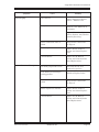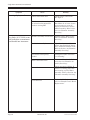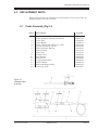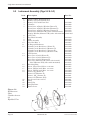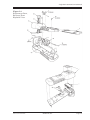
1
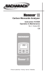
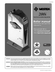
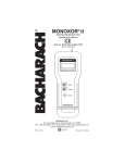
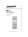
INSTRUCTION 0019-9166
COMBINED SERVICE MANUAL for:
DIOXOR® II
MONOXOR® II
MONOXOR® II H (High Range)
NONOXOR® II
Rev. 7 – May 2010
Bacharach, Inc.
621 Hunt Valley Circle, New Kensington, PA 15068
Phone: 1-800-736-4666 • Fax: 724-334-5001 • Web: www.mybacharach.com
Printed in the U,S.A.
® Bacharach, Dioxor, Monoxor, and Nonoxor are registered trademarks of Bacharach, Inc.
Copyright © Bacharach 1997-2010, all rights reserved.
A
TABLE OF CONTENTS
1.0
SERVICE MANUAL CONTENTS.................................................................4
2.0
MAINTENANCE ............................................................................................5
2.1
2.2
2.3
2.4
2.5
2.6
3.0
Opening the Case..................................................................................5
Closing the Case....................................................................................6
Cleaning........................................................................................7
Sensor Replacement..............................................................................9
Printed Circuit Board Replacement.....................................................10
Chamber Assembly Servicing..............................................................11
SENSOR CALIBRATION............................................................................12
3.1
3.2
Monoxer II CO Calibration.................................................................12
Dioxor II SO2, Monoxor II H CO, and Nonoxor II NOx Calibration...13
4.0
TROUBLESHOOTING CHART ................................................................14
5.0
REPLACEMENT PARTS.............................................................................17
5.1
5.2
5.3
5.4
Probe Assembly .................................................................................17
Instrument Assembly ..........................................................................18
Miscellaneous Parts and Accessories.................................................20
BACHARACH Sales/Service Centers...............................................20
Single Gas Instrument Service Manual
1.0
SERVICE MANUAL CONTENTS
This manual contains the following service information for the . . .
DIOXOR II (Part No. 0019-7038 & 0019-7043)
MONOXOR II (Part No. 0019-7034 & 0019-7039)
MONOXOR II H (Part No. 0019-8015)
NONOXOR II (Part No. 0019-7036 & 0019-7042).
NOTE: The 0019-7039, 0019-7042, and 0019-7043 versions of these
instruments do not contain a probe, all non-probe related functions
remain the same in this instruction.
• Instrument maintenance, which includes information on how to:
• Open and close the case
• Clean the Fan Assembly and chamber assembly area
• Replace the sensor
• Replace the Printed Circuit Board (P.C.B.)
• Service the gas-sensing chamber assembly (chamber assembly)
• Sensor calibration
• Troubleshooting chart
• Replacement parts list
GENERAL NOTE
If excessive torque is applied to the instrument's
fasteners, poor performance or damage to components
may occur.
The torque specifications are as follows:
Screws
Sensor Mounting
Motor Mounting
Chamber Sealing
Rear Cover/Case
Fan Assembly
Page 4
Bacharach, Inc.
Torque
4-8
6-10
16-20
18-24
32-40
oz. in.
oz. in.
oz. in.
oz. in.
oz. in.
Instruction 0019-9166
Single Gas Instrument Service Manual
2.0
MAINTENANCE
2.1
Opening the Case
Equipment Needed:
• Phillips-head screwdriver, No. 1
Procedure:
1. Lay the instrument face down on a workbench; then detach the metal clip
from the bottom of case and fold the elastic strap over top of the instrument
(Fig 2-1).
2. Slide off battery cover.
3. Remove batteries.
4. Using a No. 1 Phillips-head screwdriver, remove the two screws from the
rear of the case.
5. Lift up the bottom portion of the rear case and slide it forward until the case
clears the inlet port.
6. To gain better access to the components, remove the gas-sensing chamber assembly (Chamber Assembly) and the Printed Circuit Board (P.C.B.) from the
front case by pulling them straight up from the front case (Fig 2-2); then lay
these items on your workbench.
Figure 2-1.
Opening and
Closing the Case
Instruction 0019-9166
Bacharach, Inc.
Page 5
Single Gas Instrument Service Manual
2.2
Closing the Case
Equipment Needed:
• Phillips-Head Screwdriver, No. 1
Procedure:
CAUTION
When replacing the P.C.B. and chamber assembly, the P.C.B. must
be installed FIRST. The P.C.B. switches could be damaged if the
P.C.B. is installed after the chamber assembly is in place.
1. Ensure that the P.C.B. is properly positioned face down over its locating-tab
on the front case (Fig 2-2).
2. Properly position the chamber assembly between the ribs of the front case.
3. Slide the rear case over the inlet port and properly join the two case halves
together.
4. Secure the case halves to each other using the two screws removed in Section 2.1, Step 4 (Tighten to 18–24 oz. in.).
5. Reinstall the batteries (observe proper battery polarity); replace the battery
cover; and attach the elastic strap’s metal clip to the bottom of the instrument.
Figure 2-2.
P.C.B. and
Chamber Assembly
Removal and
Installation
Page 6
Bacharach, Inc.
Instruction 0019-9166
Single Gas Instrument Service Manual
2.3
Cleaning
The inside of the chamber assembly is the only part of the instrument that needs
to be cleaned. To clean the chamber assembly, proceed as follows:
Equipment Needed:
•
•
•
•
Screwdriver, No. 1 Phillips head
Screwdriver, 1/8" flat-blade
Warm soapy water
Allen Wrench, .05 in.
• Clean rags
• Cotton Swabs
• Pipe cleaners
Procedure:
1. Open the case as described in Section “2.1 Opening the Case.”
2. Using a flat-blade screwdriver, remove the three screws and nuts that secure
the Sensor to the chamber assembly; DO NOT remove the sensor wires.
Then remove the Sensor along with its O-ring and Membrane from the
chamber assembly.
3. Using a No. 1 Phillips-head screwdriver, disassemble the chamber assembly
by removing the two screws and nuts that secure the Chamber to the Motor
Assembly
(Fig 2-3).
NOTE: Do not remove the Fan Assembly unless it's absolutely necessary for cleaning or repair purposes.
4. If it is necessary to remove the Fan Assembly, first loosen the set screw on
the Fan Assembly with the .05 in. Allen wrench, and then pull off the assembly.
NOTE: It is not necessary to disassemble the Motor Assembly. If
motor replacement is required, refer to Section 2.6, Step 5.
5. Clean the Fan Assembly, Chamber & Motor Assembly (see Fig 2-3) using
cotton swabs and clean rags dampened with warm, soapy water. After cleaning, dry all parts with clean dry rags and cotton swabs.
NOTE: Replace, DO NOT CLEAN, the Membrane (Fig 2-2) if dirty.
6. Clean the Chamber’s inlet and outlet ports using pipe cleaners dipped in
warm, soapy water. After cleaning, dry them with clean dry pipe cleaners.
7. Reassemble the chamber assembly as follows:
NOTE: DO NOT overtighten any screws; damage to plastic parts
will result.
Instruction 0019-9166
Bacharach, Inc.
Page 7
Single Gas Instrument Service Manual
a. If disassembled, push the Fan Assembly onto the Motor shaft until it seats
(Fig 2-3). Be sure the set screw (Fig 2-3A) is not screwed in so far that it
prevents the adapter from seating fully. Tighten the set screw to approximately 32–40 ounce-inches using the .05 in. Allen wrench. Spin the Fan
Assembly to be sure it will run in the chamber.
b. Mate and secure the Chamber and Motor Assembly together with the
two screws and nuts removed in Step 3 (Tighten to 16–20 oz. in.).
8. Reinstall the Membrane (mesh side toward the chamber assembly), O-ring,
and Sensor on the chamber assembly (Fig 2-2); then secure the Sensor using
the three screws and nuts removed in Step 2 (Tighten to 4–8 oz. in.).
9. Close the case as per Section “2.2 Closing the Case.”
Figure 2-3.
Chamber Assembly, Exploded
View
Figure 2-3A.
Fan-blade assembly set screw
Page 8
Bacharach, Inc.
Instruction 0019-9166
Single Gas Instrument Service Manual
2.4
Sensor Replacement
When the instrument can no longer be spanned, as described in Section “3.0 Sensor Calibration,” the Sensor has reached the end of its useful life, and should be
replaced. The life of a Sensor is typically two years. The Sensor may also need
to be replaced if the instrument will not zero properly, or if erratic gas readings
occur. Refer to Section “4.0 Troubleshooting Chart.”
Equipment Needed (Refer to Section “5.0 Replacement Parts” for Part
Nos.):
•
•
•
•
Phillips-head screwdriver, No. 1
Nutdriver, 4mm (5/32")
Screwdriver, 1/8" flat blade
O-Ring and Membrane, if required
Procedure:
•
•
•
•
•
Replacement Sensor:
Dioxor II - SO2
Monoxor II - CO
Nonoxor II - NOX
Monoxor II H - CO
WARNING!
Burn hazard! The Sensors contain corrosive chemicals,
DO NOT puncture or take the sensors apart.
1. Open the case as described in Section “2.1 Opening the Case.”
2. Using a nutdriver, loosen the nuts that secure the sensor wires to the Sensor terminals R, S and C; then remove the wires. If the Sensor has pin and
socket connections, simply pull the sockets from the sensor pins.
3. Using a flat-blade screwdriver, remove the three screws and nuts that secure
the Sensor to the chamber assembly; then remove the Sensor along with its
O-ring and Membrane from the chamber assembly.
4. Remove and discard of the old Sensor in accordance with local and federal
regulations. DO NOT discard the sensor’s O-ring and Membrane, unless you
intend to replace these items.
NOTE: Replace the O-ring if it looks deformed, and replace the
Membrane if it is contaminated with oil or dirt. We recommend
that both the O-ring and Membrane be replaced at the same time.
5. Remove the new Sensor from its shipping canister. Do not remove the shorting wire (across the R & S terminals) from the Sensor (SO2 & CO only, the
NOX does not have a shorting wire) until you are ready to make the electrical
connection.
6. Position the Membrane, O-ring, and new Sensor on the chamber assembly
as per Fig 2-2. Ensure that the sensor terminals are positioned as shown.
Secure these items to the chamber assembly using the screws and nuts removed in Step 3 (Torque to 4–8 oz. in.). DO NOT overtighten the screws!
7. Remove the shorting wire from the R & S terminals (SO2 & CO only). Connect the blue (S), red (R), and black (C) wires from the P.C.B. to their associated sensor terminals (See Fig 2-4). If the Sensor uses nuts to secure the
Sensor wires, DO NOT overtighten these connections!
8. Close the case as per Section “2.2 Closing the Case.”
9. Calibrate the new Sensor as per Section “3.0 Sensor Calibration.”
Instruction 0019-9166
Bacharach, Inc.
Page 9
Single Gas Instrument Service Manual
2.5
Printed Circuit Board (P.C.B.) Replacement
Equipment Needed (Refer to Section “5.0 Replacement Parts” for Part
Nos.):
• Phillips-head screwdriver, No. 1
• Printed Circuit Board (P.C.B.)
Procedure:
1. Open the case as described in Section “2.1 Opening the Case.”
2. Unplug the motor connector from the P.C.B.
3. Unplug the sensor connector from the P.C.B.
NOTE: (For SO2 & CO Sensors only) If the Sensor is not going to
be immediately plugged into the new P.C.B., place a shorting wire
between sensor terminals R and S.
4. Remove the Switch Covers from the old P.C.B. and place them on the new
P.C.B., then replace the old P.C.B. with the new one.
5. Plug the motor connector into the P.C.B.
6. Remove the shorting wire from sensor terminals R & S (if installed); then
plug the sensor connector into the P.C.B.
7. Close the case as per Section 2.2 Closing the Case.”
8. Calibrate the Sensor with the new P.C.B. as per Section “3.0 Sensor Calibration.”
9. Discard the old P.C.B.
Figure 2-4.
Sensor & Motor
Wiring Diagram
Page 10
Bacharach, Inc.
Instruction 0019-9166
Single Gas Instrument Service Manual
2.6
Chamber Assembly Servicing
To disassemble the chamber assembly, proceed as follows:
Equipment Needed (Refer to Section “5.0 Replacement Parts” for Part
Nos.):
•
•
•
•
Screwdriver, Phillips head, No. 1
Screwdriver, 1/8" flat-blade
Allen Wrench, .05 in.
Replacement pump parts, as required
Procedure:
1. Open the case as described in Section “2.1 Opening the Case.”
2. Using a flat-blade screwdriver, remove the three screws and nuts that secure
the Sensor to the chamber assembly; DO NOT remove the sensor wires.
Then remove the Sensor along with its O-ring and Membrane from the
chamber assembly.
3. Using a No. 1 Phillips-head screwdriver, disassemble the Chamber from the
Motor Assembly (Fig 2-3).
4. To remove the Fan Assembly, refer to Section 2.3, Step 4.
5. If Motor replacement is required:
a. Unplug the motor connector from the circuit board and discard the Motor
Assembly.
b. Install a new Motor Assembly and connect the motor connector to the
circuit board.
NOTE: A newly installed Motor must be broken in by running it
for at least 30 minutes. A Motor not broken in may cause erratic
display readings.
6. Reassemble the chamber assembly with any replacement parts using Section
2.3, Step 7.
7. Reinstall the Membrane, O-ring, and Sensor using Section 2.3, Step 8.
8. Close the case as per Section “2.2 Closing the Case.”
Instruction 0019-9166
Bacharach, Inc.
Page 11
Single Gas Instrument Service Manual
3.0
SENSOR CALIBRATION
3.1 Monoxor II CO Calibration
The following calibrates the MONOXOR II to a known concentration of carbon
monoxide.
Equipment Needed (Refer to Section “5.0 Replacement Parts” for Part
Nos.):
• Calibration Kit
• Carbon Monoxide Gas Cylinder, 500 ppm
• Potentiometer adjustment tool
Procedure:
WARNING!
Perform this procedure in a well ventilated area. CO is toxic!
1. Assemble the calibration equipment by connecting the Carbon Monoxide Gas
Cylinder and the components of the Calibration Kit together as shown in Fig
3-1.
NOTE: DO NOT attach the calibration setup to the instrument at this
time.
2. Zero the instrument as follows:
a. Ensure instrument will be sampling CO-free (fresh) air in the following
steps.
NOTE: An indication that the instrument was not zeroed in fresh air
is when a large negative CO display appears when the instrument is
moved into another area.
b. Set front panel POWER switch to ON.
Figure 3-1.
Calibration Kit
Setup
Page 12
Bacharach, Inc.
Instruction 0019-9166
Single Gas Instrument Service Manual
Important! Do not proceed with this calibration procedure if the instrument’s “LO BAT”
indicator is on. We recommend that the instrument be calibrated with a fresh set of batteries.
c.
Wait until the instrument’s CO display settles down (approximately 1 minute); then, using
a potentiometer adjustment tool, turn the front panel ADJUST potentiometer (Fig 3-2) until
the display shows 0 ±3 ppm. The display shows negative numbers for zeroing purposes.
Figure 3-2.
ADJUST &
CO Span
Adjustments
3. Connect the CO discharge hose of the calibration equipment to the Monoxor's probe tip; then
open the CO cylinder regulator valve and adjust the regulator for a flowmeter indication of 1
to 2 SCFH.
4. Allow gas to flow for 2 minutes.
5. Read the detected CO level on the instrument’s LCD. Then using a potentiometer adjustment
tool, adjust the CO SPAN potentiometer until the LCD reading matches the gas cylinder’s
concentration value within ±5 ppm.
6. Shut off the regulator and remove the CO discharge hose from the gas inlet port. Then while
observing the displayed CO level, allow the instrument to run until the CO reading drops to
zero.
NOTE: If after 5 minutes the CO reading stabilizes at some value other than zero, readjust the
ADJUST potentiometer for an LCD indica
tion of ±3 ppm.
7. Set front panel POWER switch to OFF.
8. Disassemble the calibration-equipment setup and store the components in the calibration kit’s
carrying case.
3.2
Dioxor SO2, Monoxor II H CO, and Nonoxor NOX Calibration
The presence of SO2 and NOX gas in small amounts, and CO gas in larger amounts, can be very toxic.
Calibration at a Bacharach Sales/Service Center is recommended (See Section “5.4 Bacharach Sales/
Service Centers” to find the nearest center). If you have a facility that is properly equipped to handle
toxic gas (i.e.. fume hoods, self contained breathing apparatus etc.), we would be glad to suggest a
calibration method.
Instruction 0019-9166
Bacharach, Inc.
Page 13
Single Gas Instrument Service Manual
4.0
TROUBLESHOOTING CHART
Symptom
No display when unit is
switched on
Backlight won't light
Unit doesn't respond to gas
(e.g., from calibration gas)
LCD segments missing
Page 14
Cause
Remedy
Batteries dead
Replace batteries with four
fresh “C” Alkaline cells.
Batteries installed backwards
Insert batteries correctly.
Wait at least one minute before switching on unit to allow
its PTC resistor to cool.
P.C.B. defective
Replace P.C.B. Refer to
Section “2.5 Printed Circuit
Board Replacement.”
Backlight or its switch is defective
Replace P.C.B. Refer to
Section “2.5 Printed Circuit
Board Replacement.”
Sensor connections loose or
broken
Check Sensor connections
(Fig. 2-2).
Sensor Membrane blocked with
water or dirt
Remove Sensor and replace
its Membrane. See Fig. 2-2.
Sensor depleted or defective
Replace Sensor. Refer to
Section “2.4 Sensor Replacement.”
P.C.B. defective
Replace P.C.B. Refer to
Section “2.5 Printed Circuit
Board Replacement.”
LCD loose or defective
Carefully re-seat LCD in its
socket. If segments are still
missing, replace LCD.
P.C.B. defective
Replace P.C.B. Refer to
Section “2.5 Printed Circuit
Board Replacement.”
Bacharach, Inc.
Instruction 0019-9166
Single Gas Instrument Service Manual
Symptom
Erratic display
Cause
Remedy
Low batteries
Replace batteries with four
fresh “C” Alkaline cells.
Faulty Motor
Break in a new Motor for at
30 minutes.
Replace Motor Assembly.
Refer to Section “2.6 Chamber
Assembly Servicing.”
Unit won't zero and/or span
Instruction 0019-9166
Sensor connections loose or
broken
Check Sensor connections.
See Fig 2-2.
Sensor depleted or defective
Replace Sensor. Refer to
Section “2.4 Sensor Replacement.”
P.C.B. defective
Replace P.C.B. Refer to
Section “2.5 Printed Circuit
Board Replacement.”
Too much gas present to zero
Move unit into an area
known to be gas free.
Probe kinked or blocked preventing gas flow
Unkink or Replace Probe.
Sensor connections loose or
broken
Check Sensor connections.
See Fig 2-2.
Sensor depleted or defective
Replace Sensor. Refer to
Section “2.4 Sensor Replacement.”
P.C.B. defective
Replace P.C.B. Refer to
Section “2.5 Printed Circuit
Board Replacement.”
Bacharach, Inc.
Page 15
Single Gas Instrument Service Manual
Symptom
Bouncing display > ± 3 counts
Cause
Sensor connections loose
Motor has excessive arcing in
its carbon brush/commutator
interface causing RFI
Very little (<0.25" H2O) or no Chamber assembly screws loose
draft indication on manometer
dead headed into instrument
Page 16
Remedy
Check Sensor connections.
See Fig 2-2.
Run Motor for at least 3 hours
to wear away arc spots. If
display still bounces, replace
Motor Assembly. Refer to Section “2.6 Chamber Assembly
Servicing.”
Tighten screws. Refer to Section “2.6 Chamber Assembly
Servicing.”
Fan-blade Assembly loose
Open chamber assembly and
ensure that Fan-blade Assembly is mounted on Motor shaft.
Refer to Section “2.6 Chamber
Assembly Servicing.”
Inlet and/or outlet port(s)
blocked
Clean ports. Refer to Section
“2.3 Cleaning.”
Motor connections loose
Reconnect Motor leads. Refer
to Section "2.6 Chamber Assembly Servicing."
Motor defective
Check operation of Motor. If
motor is receiving power but
isn’t turning, replace Motor
Assembly. Refer to Section “2.6
Chamber Assembly Servicing.”
P.C.B. defective
Replace P.C.B. Refer to Section “2.5 Printed Circuit Board
Replacement.”
Bacharach, Inc.
Instruction 0019-9166
Single Gas Instrument Service Manual
5.0
REPLACEMENT PARTS
Replacement parts for the instrument are listed below. Please refer to the appropriate figure(s) for part locations.
5.1
Probe Assembly (Fig 5-1)
Item
1
-2
3
4
5
6
7
8
9
10
11
12
13
14
15
Description
Part No.
Probe Assembly, Standard
Probe Assembly, Flexible (not shown)
Probe Tube
Probe Handle
Screw, Phillips head, M3 x .5 x 8 mm
Tubing, 5/16 OD X 3/16 ID
Filter Saturator Bushing
Filter Packing
Filter Tube
Front Ferrule
Rear Ferrule
Knurled Nut
Compression Fitting
Barbed Fitting
Extended Adapter Block
Connector Tube
0019-3076
0019-3104
0019-3073
0019-3017
0501-3806
0003-6109
0011-0074
0011-0121
0011-0130
0003-2024
0003-2025
0003-2023
0003-2021
0003-6164
0019-3072
0011-0070
Figure 5-1.
Standard Probe
Assembly
Instruction 0019-9166
Bacharach, Inc.
Page 17
Single Gas Instrument Service Manual
5.2
Instrument Assembly (Figs 5-2 & 5-3)
Item
1
2
3
4
5
6
7
8
9
10
11
12
13
14
15
16
17
18
19
20
21
22
23
24
Description
Part No.
Adapter, Motor Shaft 0024-0412
Battery Clip, push on 0004-3113
Battery Cover with Foam Pad
0019-3029
Chamber
0019-3090
Front Cover w/Display Window (Dioxor II)
0019-3079
Front Cover w/Display Window (Monoxor II)
0019-3055
Front Cover w/Display Window (Nonoxor II)
0019-3078
Front Cover (Monoxor II H) (order with 0019-0437) 0019-3014
Display Window (Monoxor II H) (order with 0019-3014)0019-0437
(Not Used)
Fan-Blade Assembly
0019-3013
LCD
0004-3700
Motor Assembly
0019-3063
Nut, Hex M2 x .4
0502-0007
O-Ring and Membrane
0024-0520
Printed Circuit Board Assy. (Dioxor II)
0019-3022
Printed Circuit Board Assy. (Monoxor II)
0019-3012
Printed Circuit Board Assy. (Nonoxor II)
0019-3020
Printed Circuit Board Assy. (Monoxor II H)
0019-3094
PTC Resistor
0204-9427
Rear Case w/ Label (Dioxor II)
0019-3082
Rear Case w/ Label (Monoxor II)
0019-3053
Rear Case w/ Label (Nonoxor II)
0019-3081
Rear Case (Monoxor II H) (order with 51-2347)
0019-3008
Label (Monoxor II H) (order with 0019-3008)
0051-2347
Retaining Ring
0002-2675
Screw, Cheese head, M2 x .4 x 30 mm
0501-3807
Screw, Phillips head, M2 x .4 x 6 mm
0501-3803
Screw, Phillips head, M3 x .5 x 8 mm
0501-3806
Sensor, SO2 (Dioxor II)
0019-8002
Sensor, CO (Monoxor II)
0024-0498
Sensor, ,NOX (Nonoxor II)
0019-8001
Sensor, CO (Monoxor II H)
0019-8016
Set Screw, #4-40 x 1/8 LG
0002-0001
Strap
0019-3028
Strap Clip
0019-3030
Strap Retainer
0019-3027
Switch Cover
0019-3021
Figure 5-2.
Replacement
Parts,
Chamber Assembly
Exploded View
Page 18
Bacharach, Inc.
Instruction 0019-9166
Single Gas Instrument Service Manual
Figure 5-3.
Replacement Parts,
Back and Front
Exploded Views
Instruction 0019-9166
Bacharach, Inc.
Page 19
5.3
Miscellaneous Parts and Accessories
Description
Calibration Kit
Carbon Monoxide Gas Cylinder, 500 ppm
Potentiometer adjustment tool
Custom Carrying Case (1 Instrument)
Custom Carrying Case (2 Instrument)
Instruction Manual, (Dioxor II)
Instruction Manual, (Monoxor II)
Instruction Manual, (Nonoxor II)
Instruction Manual, (Monoxor II H)
Calibration Card
Service Manual, (This Manual)
Label, Carrying Case
Probe Stop (for Securing ¼ Probe in a Flue or Stack)
Warranty Card
5.4
BACHARACH Sales/Service Centers
United States
Bacharach, Inc.
621 Hunt Valley Circle
New Kensington, PA 15068
Phone: 724-334-5051
Fax: 724-334-5723
E-mail: [email protected]
Canada
Bacharach of Canada, Inc.
20 Amber St. Unit #7
Markham, Ontario L3R SP4
Canada
Phone: 905-470-8985
Fax: 905-470-8963
Email: [email protected]
Part No.
0024-7059
0024-0492
0006-9456
0019-0377
0019-3040
0019-9121
0019-9113
0019-9120
0019-9180
0019-9150
0019-9166
0019-3077
0024-0434
0006-8825