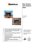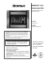
1
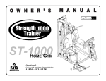
M38DV-ST (MH) Conversion Kits Manufactured/ Mobile Home Approved Fireplace RCV708 Conversion to LP RCV808 Conversion to Natural Gas This appliance may be installed as an OEM installation in a manufactured (mobile) home and must be installed in accordance with the manufacturer's instructions and the manufactured home construction and safety standard, Title 24 CFR, Part 3280 or Standard for Installation in Mobile Homes, CAN / CSA Z240 MH. This appliance is only for use with the type(s) of gas indicated on the rating plate. A conversion kit is supplied with the appliance. Warning: If the information in these instructions is not followed exactly, a fire or explosion may result causing property damage, personal injury or loss of life. Do not store or use gasoline or other flammable vapors and liquids in the vicinity of this or any other appliance. What To Do If You Smell Gas: • Do not try to light any appliance. • Do not touch any electrical switch; do not use any phone in your building. • Immediately call your gas supplier from a neighbor's phone. Follow the gas supplier's instructions. • If you cannot reach your gas supplier, call the fire department. Installation and service must be performed by a qualified installer, service agency or the gas supplier. Check local codes and read all instructions prior to installation. Leave this manual with the owner. M38DV-ST (MH) Gas Conversion Kit Table Of Contents General Information.................................................................. 2 Parts list..................................................................................... 2 A.Conversion General Information This gas conversion kit contains the necessary components for field conversion of an approved Montigo fireplace from Natural Gas (NG) to Liquid Propane (LP), or from LP to NG. See this kit for use with the following manufactured (mobile) home models: 1. Before you begin......................................................... 3 M38DV-ST (MH) 2. Ember Burner.............................................................. 3 3. Main Gas Regulator.................................................... 3 4. Pilot Assembly............................................................. 3 5. Main Burner................................................................ 4 A manufactured (mobile) home OEM installation in the United States must conform with the Manufactured Home Construction and Safety Standard, Title 24 CFR, Part 3280, or, when such a standard is not applicable, the Standard for Manufactured Home Installations, ANSI / NCSBCS A225.1. In Canada, the installation must conform to the Standard for Gas Equipped Recreational Vehicles and Mobile Housing, CSA Z240.4. B. Check the Gas Pressure....................................................... 4 C. Adjusting the Pilot Burner................................................... 4 Operation.................................................................................... 5 The installation of this unit must also conform with local codes or, in the absence of local codes, with the American National Fuel Gas Code, ANSI Z223.1, or the Canadian Installation Code, CAN / CGA B149. WARNING! This conversion kit shall be installed by a qualified service agency in accordance with the manufacturer's instructions and all applicable codes and requirements of the authority having jurisdiction. If the information in these instructions is not followed exactly, a fire, explosion or production of carbon monoxide may result causing property damage, personal injury or loss of life. The qualified service agency is responsible for the proper installation of this kit. The installation is not proper and complete until the operation of the converted appliance is checked as specified in the manufacturer's instructions supplied with this kit. Parts List Page Quantity Description 2 Sleeves (main burner) 1 Pilot burner orifice 1 Ember burner orifice 1 Main burner orifice 1 Label for rating plate indicating conversion 1 Label for gas control valve indicating conversion P/N XG0634 M38DV-ST (MH) Gas Conversion Kit Gas Conversion Instructions A. Conversion Pilot Assembly: CAUTION - Before you begin: 1. Shut off gas at the shut-off valve and disconnect the electrical supply (if used). 2. Remove the glass door as shown in the installation instructions and remove the logs. Flip down the lower trims to access the Ember Burner: 3. Disconnect the 1/4" tubing from the fitting on the underside of the pan base. Disconnect the fitting from the inlet side of the gas control valve. 4. Spin off the coupling just above the tee. The gas valve assembly will drop out of the way, allowing access to the coupling. 5. Uncrew the coupling assembly from the pan base. The orifice is located at top end of coupling. Unscrew it and install the orifice from the package marked 'Ember Burner Orifice' in this kit to convert to the new gas. Figure 2. Sit 820 Convertible Valve. 9. Remove pilot hood/ orifice cap by pulling it off the pilot assembly. The cap will snap off with slight pressure; the orifice must be removed with an allen key. (See Figure 4) 10. Install the new orifice from the package marked 'Pilot Orifice' in Main Gas Control Regulator: Figure 1a. Accessing the ember burner orifice. Figure 3. The Pilot Assembly. this kit to convert to the pilot to the new gas. Tighten the orifice securely with an allen key. Re-attach the pilot hood, making sure the notch in the hood lines up with the tab on the pilot assembly. Figure 1b. Changing the ember burner orifice. 6. Before re-assembling the gas tubing, the gas valve must be converted to operate on the new gas. Change the regulator on the SIT Nova gas valve. Note: This fireplace has a flip-over regulator, and needs no extra parts to convert. 7. To convert from one gas to another, simply unscrew the regulator, turn over and reinstall. One face of regulator is stamped NG, the other is marked LPG. The outer face of screw will indicate the correct gas. Figure 4. The Pilot Assembly, with cap off. The pilot hood will snap off; the orifice must be removed with an allen key. 8. Reassemble the gas fittings. P/N XG0634 Page M38DV-ST (MH) Gas Conversion Kit Gas Conversion Instructions B. Checking the Gas Pressure Main Burner 11. Remove cover plate on both ends of the main (center) burner and remove main burner tube. (See figure 5) 12. Loosen the set screws at each end of the burner tube. Slide the sleeves out of each end of the tube and replace them with the ones from the package marked 'Main Burner Sleeves' in this kit. (See Inset, Figure 6.) Re-tighten the set screws. 13. Remove the orifices from the orifice holder at each end and replace them with the new orifices from the package marked 'Main Burner Orifices' in this kit. (See Figure 6.) Make sure the Orifices are tightened securely to prevent gas leaks. 17. To check the Inlet and Manifold gas pressures, use a Water Column Pressure Gauge with 5/16" dia. tubing. Make sure the gas shut-off valve is closed, then attach the gauge to the Manifold Pressure Test Connection by loosening the screw shown in Figure 7. The tubing must be tight in the connection to prevent gas leaks. Measure the Manifold Pressure and compare the value against the chart below. Power Generator Pilot Adjustment Screw Wall Switch 14. Re-install the main burner, making sure you center the burner between the two orifices. Ensure that the burner's flame ports are pointed 90 degrees to the horizontal. Secure the burner by re-attaching both cover plates. Checking Your Conversion Inlet Pressure Manifold Pressure Test Connection Figure 7. Sit Nova 820 gas valve. Manifold Pressure (min.) Inlet Pressure (min.- max.) Natural Gas Liquid Propane 3.5" W.C. 10" W.C. 5.5" - 14" W.C. 11" - 14" W.C. " W.C. = inches water column 18. Turn off the fireplace and close the shutoff valve. Remove the test gauge. Re-tighten the test connection screw to prevent gas leakage. Figure 5. Main Burner. 19. Repeat the procedure for the Inlet Pressure. 20. If the pressure readings are not within the limits set out, contact the factory. If the pressure readings are correct, ensure that both test connection screws are tightened securely, to prevent a gas leak. C. Pilot Burner Adjustment Inset. Remove screw to release sleeve. 21.Locate the Pilot Adjustment Screw. (See figure 7) 22.Adjust pilot screw to provide properly sized flame. To increase the flame, turn the screw counterclockwise. To decrease the flame, turn it clockwise. (The flame should impinge on the thermocouple and thermopile, as shown in Figure 8) Figure 6. Changing main burner orifice. 15. Leak test using a soap solution with main burner turned on. Coat pipe and tubing joints, gasket etc. with soap solution. Bubbles indicate leaks. Tighten any areas where the bubbles appear until the bubbling stops completely. 16. Light the fireplace pilot, and turn the gas control knob to the ON position. Ensure all three burners light properly. 6. Re-Assembly Replace the logs, re-install the door and the door surround. Page Figure 8. Pilot Burner P/N XG0634 M38DV-ST (MH) Gas Conversion Kit Operating Instructions For Your Safety - READ BEFORE LIGHTING: WARNING: If you do not follow these instructions exactly, a fire or explosion may result causing property damage, personal injury or loss of life. A. This appliance has a pilot which must be lighted by hand. When lighting the pilot, follow these instructions exactly. B. BEFORE LIGHTING smell all around the appliance area for gas. Be sure to smell next to the floor because some gas is heavier than air and will settle on the floor. What To Do If You Smell Gas: Do not try to light any appliance. Do not touch any electrical switch; do not use any phone in your building. Immediately call your gas supplier from a neighbour's phone. Follow the gas supplier's instructions. If you cannot reach your gas supplier, call the Fire Department. C. Use only your hand to push in or turn the gas control knob. Never use tools. If the knob will not push in or turn by hand, don't try to repair it, call a qualified service technician. Force or attempt to repair may result in a fire or explosion. D. Do not use this appliance if any part has been under water. Immediately call a qualified service technician to inspect the appliance and to replace any part of the control system, and any gas control which has been under water. Lighting Instructions: 1. 2. 3. 4. STOP! Read the safety information above on this label. Flip down the lower trims. Push in gas control knob and turn clockwise to "OFF." Wait five (5) minutes to clear out any gas. Smell for gas, including near the floor. If you then smell gas, STOP! Follow "B" in the safety information above on this label. If you don't smell gas, go to the next step. 5. Locate pilot burner (See illustration at right.) and follow steps below. 6. Turn knob on gas control counterclockwise to "PI- Gas Control Knob (Shown in "Pilot" postion.) NOTE: Knob cannot be turned from "PILOT" to "OFF" unless knob is pushed in slightly. Do not force. LOT." 7. Push in gas control knob completely and hold. Light with Piezo Igniter button. Continue to hold the control knob in for about (1) minute after the pilot is lit. Release the knob and it will pop back up. Pilot should remain lit. If it goes out repeat steps 3 through 8. If knob does not pop up when released. Stop and immediately call your service technician or gas supplier. If the pilot will not stay lit after several tries, turn the gas control knob to "OFF" and call your service technician or gas supplier. 8. Push in gas control knob and turn counterclockwise to "ON." 9. Flip up the lower trim. 10.Turn on remote switch to ignite fire. To Turn Off Gas To Appliance: 1. Turn off remote switch. 2. Flip down the lower trim. P/N XG0634 3. Push in gas control knob slightly and turn to "Off". Do not force. 4. Flip up the lower trim. clockwise Page XG0634 Rev. 03 - 01/2002 Canadian Heating Products Inc. Montigo Del Ray Corp. Surrey, BC V3W 2V6 Ferndale, WA 98248