1
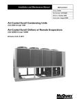
Installation, Operation and Maintenance Manual
IOMM ACZ/AGZ-3
Group: Chiller
Part Number: 330411901
Effective: October 2004
Supersedes: IOMM ACZ/AGZ-2
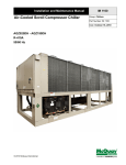
Air-Cooled Scroll Condensing Units
ACZ 030B through 155B
Air-Cooled Scroll Chillers w/ Remote Evaporators
AGZ 026BM through 130BM
60 Hertz, R-22
Table of Contents
Introduction .................................................... 3
General Description .................................................... 3
Inspection.................................................................... 3
Nomenclature .............................................................. 3
Installation ...................................................... 4
Handling...................................................................... 4
Location ...................................................................... 5
Sound Isolation ......................................................... 12
Vibration Isolators..................................................... 12
Ambient Temperature and Water Flow Limitations... 14
Water Piping (Model AGZ-BM) ............................... 14
ACZ Compressor Staging ......................................... 21
Remote Evaporator Refrigerant Piping ..................... 21
Evaporator Flow and Pressure Drop ......................... 22
Wind Baffles and Hail Guards .................................. 24
Table of Contents ...................................................... 91
Overview................................................................... 92
ACZ-B Inputs/Outputs .............................................. 92
Setpoints ................................................................... 94
Logging..................................................................... 96
Control Logic............................................................ 96
Unit Mode Selection ................................................. 97
Compressor Control .................................................. 97
Condenser Fan Control ........................................... 100
Optional VFD Low Ambient Fan Control............... 102
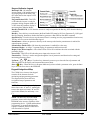
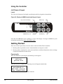
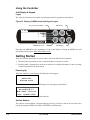
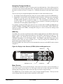
Using the Controller................................................ 112
Screen Definitions................................................... 115
Start-up........................................................ 123
Electrical Data Standard Ambient.............. 31
Pre Start-up ............................................................. 123
Start-Up................................................................... 123
Shutdown ................................................................ 124
Water Piping Checkout ........................................... 124
Refrigerant Piping Checkout................................... 124
Electrical Check Out ............................................... 125
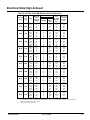
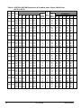
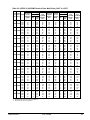
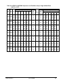
Electrical Data High Ambient ..................... 41
Operation .................................................... 125
Physical Data ................................................ 26
Dimensional Data ......................................... 50
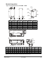
Remote Evaporators.................................................. 53
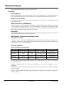
Optional Features ......................................... 54
AGZ MicroTech II¥
¥ Controller.................. 57
Table of Contents ...................................................... 57
Overview................................................................... 58
AGZ-B Inputs/Outputs.............................................. 58
Logging ..................................................................... 62
Control Logic ............................................................ 63
Chilled Water Pump Control ..................................... 64
Compressor Control .................................................. 64
Standard Condenser Fan Control .............................. 68
Optional VFD Low Ambient Fan Control ................. 69
Using the Controller.................................................. 78
Screen Definitions:.................................................... 81
View Menus .............................................................. 81
ACZ Microtech II
Controller .................. 91
Hot Gas Bypass (Optional) ..................................... 125
VFD Low Ambient Control (Optional) ................... 126
Filter-Driers (AGZ-BM) ......................................... 126
System Adjustment.................................................. 126
Liquid Line Sight Glass and Moisture Indicator ..... 126
Refrigerant Charging............................................... 126
Thermostatic Expansion Valve................................ 126
Crankcase Heaters................................................... 127
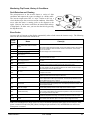
Unit Maintenance ....................................... 128
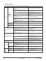
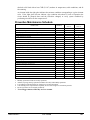
Preventive Maintenance Schedule .......................... 129
Service ......................................................... 130
Liquid Line Solenoid Valve .................................... 130
Remote Evaporator (AGZ-BM Only) ..................... 131
Refrigerant Charging............................................... 131
Warranty Statement ................................... 132
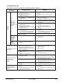
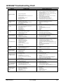
ACZ/AGZ Troubleshooting Chart............ 133
"McQuay" is a registered trademark of McQuay International
2004 McQuay International
Illustrations and data cover McQuay International products at the time of publication and we reserve the right to
make changes in design and construction at anytime without notice.
2
ACZ / AGZ-BM
IOMM ACZ/AGZ-3
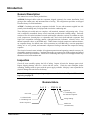
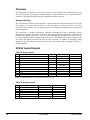
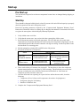
Introduction
General Description
This manual covers two similar product lines:
AGZ-BM, Packaged chiller with the evaporator shipped separately for remote installation, field
piping to the outdoor unit, and interconnection of wiring. The refrigeration specialties are shipped
from the factory for field installation.
ACZ-BC, Condensing unit with no evaporator included. For use with customer supplied low side
(usually an air-handling unit), field piped and wired to the condensing unit.
These McQuay air-cooled units are complete, self-contained, automatic refrigerating units. Every
unit is completely assembled, factory wired, tested and provided with a holding charge. Each unit
consists of two air-cooled condenser sections with integral subcooler sections, two tandem or triple
scroll compressors, (brazed-plate or replaceable tube, dual circuit shell-and-tube evaporator and
liquid line components including manual, sight-glass/moisture indicators, solenoid valves, and
thermal expansion valves on AGZ-BM only). Other features include compressor crankcase heaters,
an evaporator heater for chilled water freeze protection (on AGZ-BM only), one-time pumpdown
during “on” or “off” periods, and automatic compressor lead-lag to alternate the compressor starting
sequence.
The electrical control center includes all equipment protection and operating controls necessary for
dependable automatic operation. Condenser fan motors are protected in all three phases and started
by their own three-pole contactors. Model ACZ condensing units require a field-supplied multi-step
thermostat wired to the outdoor unit.
Inspection
Check all items carefully against the bill of lading. Inspect all units for damage upon arrival.
Report shipping damage and file a claim with the carrier. Check the unit nameplate before
unloading, making certain it agrees with the power supply available. McQuay is not responsible for
physical damage after unit leaves the factory.
Note: Unit shipping and operating weights are available in the Physical Data tables
beginning on page 26.
Nomenclature
A G Z - XXX B M
Application
C= Condensing Unit
M= Remote Evaporator
Air-Cooled
G=Global Chiller
C=Condensing Unit
Design Vintage
Scroll Compressor
IOMM ACZ/AGZ-3
Model Size
(Nominal Tons)
ACZ / AGZ-BM
3
Installation
Note: Installation is to be performed by qualified personnel who are familiar with local
codes and regulations.
WARNING
Sharp edges on unit and coil surfaces are a potential hazard to personal safety. Avoid
contact with them.
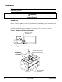
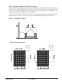
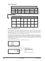
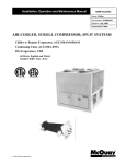
Handling
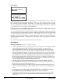
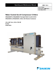
Be careful to avoid rough handling of the unit. Do not push or pull the unit from anything other than
the base. Block the pushing vehicle away from the unit to prevent damage to the sheet metal cabinet
and end frame (see Figure 1).
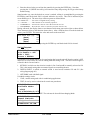
To lift the unit, 2 1/2" (64mm) diameter lifting tabs are provided on the base of the unit. Arrange
spreader bars and cables to prevent damage to the condenser coils or cabinet (see Figure 2).
Figure 1, Suggested Pushing Arrangement
Blocking is required
across full width
Figure 2, Suggested Lifting Arrangement
Spreader bars
required
(use caution)
Number of fans may vary
from this diagram. The lifting
method will remain the same.
All rigging locations
must be used.
4
ACZ / AGZ-BM
IOMM ACZ/AGZ-3
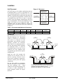
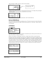
Location
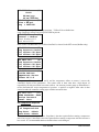
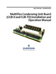
Figure 3, Clearances
Unit Placement
ACZ/AGZ units are for outdoor applications and can
be mounted either on a roof or at ground level. For
roof mounted applications, install the unit on a steel
channel or I-beam frame to support the unit above the
roof. For ground level applications, install the unit on
a substantial base that will not settle. A one-piece
concrete slab with footings extended below the frost
line is recommended. Be sure the foundation is level
within 1/2"(13mm) over its length and width. The
foundation must be strong enough to support the
weights listed in the Physical Data Tables beginning
on page 26.
SEE TABLE BELOW
DIMENSION “A”
4 FT. (1220mm)
CLEARANCE FOR
SERVICE ACCESS
4 FT. (1220)
CLEARANCE FOR
SERVICE ACCESS
SEE TABLE BELOW
DIMENSION “A”
Table 1, Recommended Minimum Clearances
ACZ-BC
Model Sizes
030B – 080B
090B – 155B
AGZ-BM
Model Size
026B – 070B
075B – 130B
Coil Side “A”
ft (m)
4 (1.2)
6 (1.8)
“B”
ft (m)
8 (2.4)
12 (3.6)
“C”
ft (m)
6 (1.8)
8 (2.4)
End Opposite
Controls ft (m)
4 (1.2)
4 (1.2)
Control Panel End
ft. (m)
4 (1.2)
4 (1.2)
Clearances
Do not block the flow of air to and
from the condenser coil. Restricting
airflow or allowing air recirculation
will result in a decrease in unit
performance and efficiency because
discharge pressures are increased.
There must be no obstruction above
the unit that would deflect discharge
air downward where it could be
recirculated back to the inlet of the
condenser coil. The condenser fans
are propeller type and will not operate
with ductwork.
Install the unit with enough side
clearance for air entrance to the coil
and for servicing. Provide service
access to the evaporator, compressors,
electrical control panel and piping
components.
AIR
DISCHARGE
AIR FLOW
AIR FLOW
IOMM ACZ/AGZ-3
AIR FLOW
“B”
The recommended minimum side clearance between two units
is dimension “B’ in table on this page.
AIR
DISCHARGE
AIR FLOW
AIR FLOW
“C”
Do not allow debris to accumulate
near the unit where it could be drawn
into the condenser coil.
Keep
condenser coils and fan discharge free
of snow or other obstructions to
permit adequate airflow for proper
operation.
AIR
DISCHARGE
“C”
The unit must not be installed in a pit or enclosure that is
deeper or taller than the height of the unit unless extra space
is provided. The minimum clearance on each
side of the unit is dimension “C” in table on this page.
ACZ / AGZ-BM
5
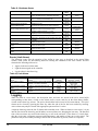
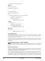
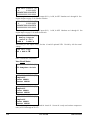
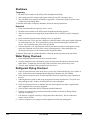
Restricted Air Flow
General
The clearances required for design-life operation of ACZ/AGZ air-cooled units are described in the
previous section. Occasionally, these clearances cannot be maintained due to site restrictions, such
as units being too close together, or a fence or wall restricting airflow, or both.
The McQuay ACZ/AGZ units have several features that can mitigate the problems attributable to
restricted airflow.
•
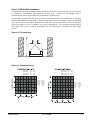
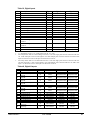
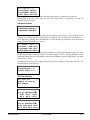
The condenser section is configured as shown below. This configuration allows inlet air for
these coils to come in from either side. A vertical coil and its adjacent angled coil are
manifolded together to serve one refrigerant circuit.
•
The MicroTech II control is proactive in response to “off-design conditions”. In the case of
single or compounded influences restricting airflow to the unit, the microprocessor will act to
keep the compressor(s) running (possibly at reduced capacity) rather than allowing a shut-off on
high discharge pressure.
•
The MicroTech II control can be programmed to sequence the compressors in the most
advantageous way. For example, in the diagram shown below, it might be desirable to program
circuit #1 to be the lag circuit (last circuit to reach full load) during periods of high ambient
temperatures.
Building
Figure 4, Coil and Fan Arrangement
Circuit #1
Circuit #2
NOTE: Models ACZ 030 to 045 and AGZ 026 to 035 do not have an interior slanted coil.
The following sections discuss the most common situations of condenser air restriction and give
capacity and power adjustment factors for each. Note that in unusually severe conditions, the
MicroTech II controller would adjust the unit operation to remain online until a less severe
condition is reached.
6
ACZ / AGZ-BM
IOMM ACZ/AGZ-3
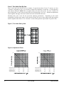
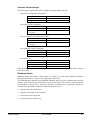
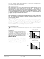
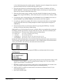
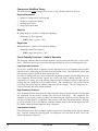
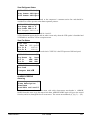
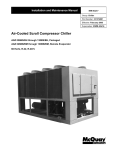
Case 1, Building or Wall on One Side of One Unit
The existence of a screening wall, or the wall of a building, in close proximity to an air-cooled unit is
common in both rooftop and ground level applications. Hot air recirculation on the coils adjoining the wall
will increase compressor discharge pressure, decreasing capacity and increasing power consumption. Only
the compressor(s) connected to these coils will be affected.
When close to a wall, place chillers on the north or east-side of them. Have prevailing winds blowing
parallel to the unit’s long axis. The worst case is to have wind blowing hot discharge air into the wall.
Figure 5, Unit Adjacent to Wall
H
D
Figure 6, Adjustment Factors
3.0
ACZ
ACZ
090-155 030-080
ACZ
ACZ
090-155 030-080
AGZ
AGZ
075-130 026-070
AGZ
AGZ
075-130 026-070
4.5 ft.
(1.4m)
3.5 ft.
(1.0m)
4.5 ft.
(1.4m)
3.5 ft.
(1.0m)
6 ft.
(1.8m)
4 ft.
(1.2m)
8 ft.
(2.4m)
6 ft.
(1.8m)
3.0
2.0
1.0
6 ft.
(1.8m)
4 ft.
(1.2m)
.5
8 ft.
(2.4m)
6 ft.
(1.8m)
0
IOMM ACZ/AGZ-3
4.0
2.0
0
ACZ / AGZ-BM
7
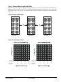
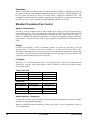
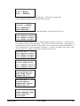
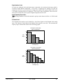
Case 2, Two Units Side By Side
Two or more units sited side by side are common. If spaced closer than 12 feet (3.7 meters), or 8 feet
(2.5meters), depending on size, it is necessary to adjust the performance of each unit. Circuits adjoining
each other are affected. NOTE: This case applies only to two units side by side. See Case 3 for three or
more parallel units. If one of the two units also has a wall adjoining it, see Case 1. Add the two adjustment
factors together and apply to the unit located between the wall and the other unit.
Mounting units end to end will not necessitate adjusting performance. Depending on the actual
arrangement, sufficient space must be left between the units for access to the control panel door opening
and/or evaporator tube removal. See “Clearance” section of this guide for requirements for specific units.
Figure 7, Two Units Side by Side
Figure 8, Adjustment Factor
3.0
6.0
2.0
4.0
1.0
2.0
0
8
0
AGZ 075-130 9
ACZ 090-155 (2.7)
10
(3.0)
11
(3.3)
12
(3.6)
AGZ 075-130 9
ACZ 090-155 (2.7)
10
(3.0)
11
(3.3)
12
(3.6)
AGZ 026-070 6.5
ACZ 030-080 (2.0)
7
(2.1)
7.5
(2.2)
8
(2.4)
AGZ 026-070 6.5
ACZ 030-080 (2.0)
7
(2.1)
7.5
(2.2)
8
(2.4)
ACZ / AGZ-BM
IOMM ACZ/AGZ-3
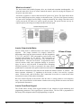
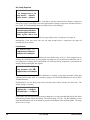
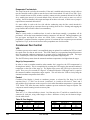
Case 3, Three or More Units Side By Side
When three or more units are side by side, the outside units (1 and 3 in this case) are influenced by the
middle unit only on their inside circuits. Their adjustment factors will be the same as Case 2. All inside
units (only number 2 in this case) are influenced on both sides and must be adjusted by the factors shown
below.
Figure 9, Three or More Units
Chiller 1
Chiller 2
Chiller 3
Figure 10, Adjustment Factor
4.0
8.0
3.0
6.0
2.0
4.0
1.0
2.0
0
0
AGZ 075-130
ACZ 090-155
15
(4.6)
16
(4.9)
17
(5.2)
18
(5.5)
AGZ 075-130
ACZ 090-155
15
(4.6)
16
(4.9)
17
(5.2)
18
(5.5)
AGZ 026-070
ACZ 030-080
11
(3.3)
12
(3.7)
13
(4.0)
14
(4.3)
AGZ 026-070
ACZ 030-080
11
(3.3)
12
(3.7)
13
(4.0)
14
(4.3)
IOMM ACZ/AGZ-3
ACZ / AGZ-BM
9
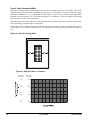
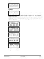
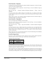
Case 4, Open Screening Walls
Decorative screening walls are often used to help conceal a unit either on grade or on a rooftop. These walls
should be designed such that the combination of their open area and distance from the unit do not require
performance adjustment. It is assumed that the wall height is equal to or less than the unit height when
mounted on its base support. This is usually satisfactory for concealment. If the wall height is greater than
the unit height, see Case 5, Pit Installation.
The distance from the ends of the unit to the end walls must be sufficient for service, opening control panel
doors, and pulling evaporator tubes, as applicable.
If each side wall is a different distance from the unit, the distances can be averaged, providing either wall is
not less than 8 feet (2.4 meters) from the unit. For example, do not average 4 feet and 20 feet to equal 12
feet.
Figure 11, Open Screening Walls
Figure 12, Wall Free Area vs. Distance
AGZ 026-070
ACZ 030-080
AGZ 075-130
ACZ 090-155
4
(1.2)
6
(1.8)
3.5
(1.0)
5
(2.0)
3.0
(0.9)
4
(1.2)
2.5
(0.7)
3
(0.9)
0
10
10
20
ACZ / AGZ-BM
30
40
50
IOMM ACZ/AGZ-3
Case 5, Pit/Solid Wall Installation
Pit installations can cause operating problems and great care should be exercised if they are to be used on
an installation. Recirculation and restriction can both occur. A solid wall surrounding a unit is
substantially the same as a pit and the data presented here should be used.
Steel grating is sometimes used to cover a pit to prevent accidental falls or trips into the pit. The grating
material and installation design must be strong enough to prevent such accidents, yet provide abundant
open area or serious recirculation problems will occur. Have any pit installation reviewed by McQuay
application engineers prior to installation for air-flow characteristics. The installation design engineer
must approve the work to avoid an unreasonable risk of accident and is responsible for final design
criteria.
Figure 13, Pit Installation
Figure 14, Adjustment Factor
AGZ 026-070
ACZ 030-080
D=4
(1.4)
D=5
(2.0)
AGZ 026-070
ACZ 030-080
D=4
(1.4)
D=5
(2.0)
AGZ 075-130
ACZ 090-155
D=6
(1.8)
D=8
(2.4)
AGZ 075-130
ACZ 090-155
D=6
(1.8)
D=8
(2.4)
AGZ
AGZ
075-130 026-070
ACZ
ACZ
090-155 030-080
D=10
D=7
(3.1)
(2.1)
IOMM ACZ/AGZ-3
ACZ / AGZ-BM
AGZ
AGZ
075-130 026-070
ACZ
ACZ
090-155 030-080
D=10
D=7
(3.1)
(2.1)
11
Sound Isolation
The low sound level of the ACZ/AGZ units is suitable for most applications. When additional sound
reduction is necessary, locate the unit away from sound sensitive areas. Avoid locations beneath
windows, or between structures where normal operating sounds can be objectionable. Reduce
structurally transmitted sound by isolating refrigerant lines, electrical conduit and the unit itself.
Use wall sleeves and rubber isolated piping hangers to reduce transmission of water, refrigerant, or
pump noise into occupied spaces. Use flexible electrical conduit to isolate sound transmission
through electrical conduit. Spring isolators are effective in reducing the low amplitude sound
generated by scroll compressors and for unit isolation in sound sensitive areas.
Vibration Isolators
Vibration isolator springs are recommended for all roof-mounted installations, or wherever vibration
transmission is a consideration. Some form of isolator is also recommended for slab installations,
primarily to keep the unit base from resting its entire length directly on the slab.
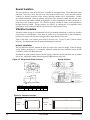
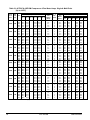
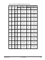
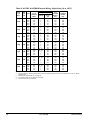
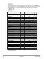
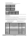
Table 2 and Table 3 list isolator point loads for all unit sizes. Figure 15 and 16 shows isolator
locations. See Dimensional Data for detailed mounting hole location.
Isolator Installation
The unit should be initially installed on shims or blocks at the listed free height. When all piping,
wiring, flushing, charging, etc., is completed, adjust the springs upward to load them and to provide
clearance to remove the shims or blocks.
Installation of spring isolators requires flexible piping connections and at least three feet of conduit
flex tie-ins. Piping and conduit must be supported independently of the unit.
Figure 15, Neoprene-in-Shear Isolators
Color Code
Gray
Black, Red
L
5.5
6.25
W
3.37
4.62
H
1.75
1.62
B
0.5
0.5
C
4.12
5.0
Spring Isolators
D
0.56
0.56
Figure 16, Isolator Locations,
4/6 FAN UNIT
8 FAN UNIT
3
4
CONTROL
PANEL
5
6
1
2
3
CONTROL
PANEL
1
12
4
2
ACZ / AGZ-BM
IOMM ACZ/AGZ-3
Table 2, Isolator Loads At Each Mounting Location (With Aluminum Fins)
ACZ-B
Model
AGZ-BM
Model
ACZ 030
AGZ 026
ACZ 035
AGZ 030
ACZ 040
ACZ 045
ACZ 050
AGZ 035
AGZ 040
AGZ 045
ACZ 055
AGZ 050
ACZ 060
AGZ 055
ACZ 065
AGZ 060
ACZ 070
AGZ 065
ACZ 080
AGZ 070
Shipping
Wt
Operating.
Wt
Loc. 1
Loc. 2
Loc. 3
Loc. 4
Total
(1) Add’l for
Copper Fins
lbs
3550
3600
1227
901
849
623
3600
72
kg
1608
1631
556
408
385
282
1631
32
lbs
3550
3600
1227
901
849
623
3600
72
kg
1608
1631
556
408
385
282
1631
32
lbs
3550
3600
1227
901
849
623
3600
72
kg
1608
1631
556
408
385
282
1631
32
lbs
3550
3610
1261
872
873
604
3610
72
kg
1608
1635
571
395
395
274
1635
32
lbs
3590
3650
1275
881
883
611
3650
72
kg
1626
1653
578
399
400
277
1653
32
lbs
3730
3800
1295
951
896
658
3800
119
kg
1690
1721
587
431
406
298
1721
54
lbs
3780
3850
1303
1016
860
671
3850
119
kg
1712
1744
590
460
390
304
1744
54
lbs
3820
4040
1367
1066
903
704
4040
142
kg
1730
1830
619
483
409
319
1830
65
lbs
3970
4070
1305
1146
862
757
4070
142
kg
1798
1844
591
519
390
343
1844
65
lbs
4080
4180
1278
1192
885
825
4180
217
kg
1848
1894
579
540
401
374
1894
99
NOTE (1): Additional weight for copper coils is per mounting location.
Table 3, Isolator Loads At Each Mounting Location (With Aluminum Fins)
ACZ
Model
AGZ-BM
Model
ACZ090
AGZ 075
ACZ100
AGZ 085
ACZ110
AGZ 090
ACZ120
AGZ 100
ACZ130
AGZ 110
ACZ140
AGZ 120
ACZ155
AGZ 130
Shipping Operating
Loc 1
Wt.
Wt.
lbs
5510
5630
1649
Loc 2
Loc 3
Loc 4
Loc 5
Loc 6
1166
1649
1166
-
-
(1)
Add’l
for
TOTAL
Copper
Fins
5630
217
kg
2496
2550
747
528
747
528
-
-
2550
99
lbs
5670
5790
1734
1227
1657
1172
-
-
5790
217
kg
2569
2623
786
556
751
531
-
-
2623
99
lbs
5830
5950
1770
1205
1770
1205
-
-
5950
217
kg
2641
2695
802
546
802
546
-
-
2695
99
lbs
6820
6970
1323
1188
1053
1265
1135
1006
6970
289
kg
3089
3157
599
538
477
573
514
456
3157
131
lbs
7080
7230
1396
1205
1014
1396
1205
1014
7230
289
kg
lbs
kg
3207
7360
3334
3275
7480
3388
632
1477
669
546
1275
578
459
1073
486
632
1411
639
546
1218
552
459
1026
465
3275
7480
3388
131
289
131
lbs
7640
7760
1555
1293
1032
1555
1293
1032
7760
289
kg
3461
3515
704
586
467
704
586
467
3515
131
NOTE (1): Additional weight for copper coils is per mounting location.
Table 4, Isolator Kit Numbers
ACZ-B Model
030 - 040
045 - 065
070
080
090 - 110
120, 130
140, 155
AGZ-BM Model
026 - 035
040 - 060
065
070
075 - 090
100, 110
120, 130
Spring Kit Part No.
330349601
330349602
330349603
330349604
330349608
330349610
330349611
R-I-S Kit Part No.
330349701
330349701
330349703
330349703
330349706
330349707
330349708
IOMM ACZ/AGZ-3
ACZ / AGZ-BM
13
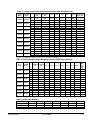
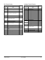
Table 5, Isolator Locations
ACZ-BS, AGZ-BM Less Evaporator Units
ACZ- AGZBM
BS
Model Model
Operating
Weight
lbs
kg
Neoprene-In-Shear Mountings
Spring-Flex Mountings
1
2
3
4
5
6
3
4 (1)
030
026
3600
1631
Black
Gray
Gray
Green
-
-
Orange Purple
1
2
Red
Orange
5
6
035
030
3600
1631
Black
Gray
Gray
Green
-
-
Orange Purple
Red
Orange
040
035
-
-
3600
1631
Black
Gray
Gray
Green
-
-
Orange Purple
Red
Orange
-
-
045
040
3610
1635
Black
Gray
Gray
Green
-
-
Orange Purple
Purple Orange
-
-
050
045
3650
1653
Black
Gray
Gray
Green
-
-
Orange Purple
Purple Orange
-
-
055
050
3800
1721
Black
Gray
Gray
Green
-
-
Orange Purple
Purple Orange
-
-
060
055
3850
1744
Black
Gray
Gray
Green
-
-
Orange Purple
Purple Orange
-
-
065
060
4040
1830
Black
Gray
Gray
Green
-
-
Orange Purple
Purple Orange
-
-
070
065
4070
1844
Black
Black
Gray
Gray
-
-
Orange Purple
Purple
Red
-
-
080
070
4180
1894
Black
Black
Gray
Gray
-
-
Orange Orange Purple
Red
-
-
090
075
5630
2550
Red
Black
Red
Black
-
-
Green Orange Green Orange
-
-
100
085
5790
2623
Red
Black
Red
Black
-
-
Green Orange Green Orange
-
-
110
090
5950
2695
Red
Black
Red
Black
-
-
Green Orange Green Orange
-
-
120
100
6970
3157
Black
Black
Black
Black
Black
Black
Orange Orange Purple Orange Orange Purple
130
110
7230
3275
Black
Black
Black
Black
Black
Black
Orange Orange Purple Orange Orange Purple
140
120
7480
3388
Red
Black
Black
Red
Black
Black
Green Orange Purple
Green Orange Purple
155
130
7760
3515
Red
Black
Black
Red
Black
Black
Green Orange Purple
Green Orange Purple
NOTE (1): Position #4 is a CP-1, single spring isolator for ACZ 030 to 065 and AGZ 026 to 060. All others are CP-2,
two spring.
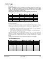
Ambient Temperature and Water Flow Limitations
ACZ/AGZ units are designed to operate in ambient temperatures as shown in the following table.
Table 6, Unit Maximum Operating Ambient Temperature
Unit Model
Standard Controls
w/ Low Ambient VFD
Control Option
w/ Low Ambient VFD Control
Plus High Ambient Panel Option
AGZ 026B – 130B
ACZ 030B – 155B
115°F
105°F
125°F
The VFD Low Ambient Control Option imposes an additional heat load on the control panel
limiting operation to 105°F ambient temperature. The addition of the High Ambient Panel
Option allows operation to 125°F ambient temperature.
Compressor loading and unloading is adaptively determined by system load, ambient air
temperature, and other inputs to the MicroTech control algorithms. An optional low ambient fan
VFD option allows operation down to 0°F (-18°C). The minimum ambient temperature is based
on still conditions where the wind is not greater than five mph. Greater wind velocities will
result in reduced discharge pressure, increasing the minimum operating ambient temperature.
Field-installed hail/wind guards are available to allow the chiller to operate effectively down to
the ambient temperature for which it was designed.
Evaporator flow rates can be found on page 23. Operation below the minimum values can result
in laminar flow causing freeze-up problems, scaling and poor control. Flow rates above the
maximum values will result in unacceptable pressure drops and can cause excessive erosion,
potentially leading to failure.
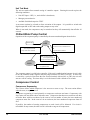
Water Piping (Model AGZ-BM)
Local authorities can supply the installer with the proper building and safety codes required for
safe and proper installation.
Install piping with minimum bends and changes in elevation to minimize pressure drop. The
following issues must be considered when designing and installing water piping:
14
ACZ / AGZ-BM
IOMM ACZ/AGZ-3
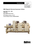
1. Vibration eliminators to reduce vibration and noise transmission to the building.
2. Shutoff valves are required to isolate the unit from the piping system during unit servicing.
3. Manual or automatic air vent valves at the high points of the system. Drains must be
installed at the lowest points in the system.
4. Adequate system water pressure must be maintained (expansion tank or regulating valve).
5. Temperature and pressure indicators located at the unit are required to aid in unit servicing.
6. A strainer or other means of removing foreign matter from the water before it enters the
pump must be installed. Place the strainer far enough upstream to prevent cavitation at the
pump inlet (consult pump manufacturer for recommendations). The use of a strainer will
prolong pump life and keep system performance up.
7. A strainer must be installed in the water line before the inlet of the evaporator. This will help
prevent foreign material from entering and decreasing the evaporator performance.
8. If the unit is used as a replacement chiller, flush the system thoroughly before unit
installation. Regular water analysis and chemical water treatment for the evaporator loop is
recommended immediately at equipment start-up.
9. The total water volume in the system should be sufficient to prevent frequent “on-off”
cycling. Turnover rate should not be less than 4 minutes for normal variable cooling loads.
10. When glycol is added to the water system for freeze protection, the refrigerant suction
pressure will be lower, cooling performance less, and water side pressure drop greater. If the
percentage of glycol is high, or if propylene is used instead of ethylene glycol, the added
pressure drop and loss of performance could be substantial. When Glycol or Ice are selected
as Unit Mode, the MicroTech controller will automatically reset the available range for the
Leaving Water Temperature, Freezestat and Evaporator Pressure settings.
Reset the freezestat setting to approximately 4 to 5 degrees F (2.3 to 2.8 degrees C) below the
leaving chilled water setpoint temperature. See the section titled “Glycol Solutions” for
additional information concerning glycol.
11. Perform a preliminary leak check before insulating the piping and filling the system.
12. Piping insulation should include a vapor barrier to prevent condensation and possible damage
to the building structure from water dripping.
Figure 17, AGZ 075BM – AGZ 130BM, Typical Field Evaporator Water Piping
THERMOWELL
T
INLET
T
IOMM ACZ/AGZ-3
ACZ / AGZ-BM
15
Figure 18, AGZ 026BM - AGZ 070BM, Typical Field Evaporator Water Piping
T
Air
Vent
Strainer
Inlet
Isolation
Valves
Vibration
Eliminators
P
Outlet
Flow
Switch
T
Thermowell
Drain
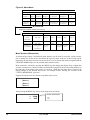
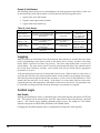
Flow Switch (Model AGZ-BM)
Mount a water flow switch in the leaving water line of the remote water chiller to shut down the unit
when water flow is interrupted. A flow switch is an equipment protection control and should never
be used to cycle a unit.
A flow switch is available from McQuay (part number 017503300). It is a “paddle” type switch and
adaptable to any pipe size from 2” (51 mm) to 6” (152 mm) nominal. Certain minimum flow rates
are required to close the switch and are listed in Table 7. Installation should be as shown in Figure
19. Connect the normally open contacts of the flow switch in the unit control center at terminals 44
and 61. There is also a set of normally closed contacts on the switch that can be used for an
indicator light or an alarm to indicate when a “no flow” condition exists. Freeze protect any flow
switch that is installed outdoors. Manufacturer’s instructions included with the switch should be
followed. NOTE: Differential pressure switches are not recommended for outdoor installation.
Table 7, Flow Switch Minimum/Maximum Flow Rates
Nominal Pipe Size
Inches (mm)
2 (50.8)
2 1/2 (63.50
3 (76.20
4 (101.6)
5 (127.0)
6 (152.4)
Minimum Required Flow To
Activate Switch - gpm (l/m)
13.7 (51.8)
17.9 (67.8)
24.2 (91.6)
35.3 (134.0)
48.6 (184.0)
60.3 (228.0)
Maximum Flow Rate
gpm (l/m)
105 (397.4)
149 (564.0)
230 (870.6)
397 (1502.7)
654 (2475.4)
900 (3406.5)
Note: See pressure drop table on page 23 for minimum and maximum flow through the evaporator.
Figure 19, Flow Switch Installation
Flow direction marked on switch
1" (25mm) NPT flow switch connection
Tee
Water Connections
Bring water piping to the evaporator through the side between the vertical supports. Provide taps for
the connection of pressure gauges and thermometers in the inlet and outlet lines. Check the inlet and
outlet labels on the unit against the certified drawings supplied on the job and be sure the water
piping is hooked up correctly. Contact the McQuay sales office if any discrepancies exist.
16
ACZ / AGZ-BM
IOMM ACZ/AGZ-3
Variable Speed Pumping
Variable water flow involves lowering the water flow through the evaporator as the load decreases.
McQuay chillers are designed for this duty provided that the rate of change in water flow is slow and
the minimum and maximum flow rates for the vessel are not exceeded.
The recommended maximum change in water flow is 10 percent of the change per minute.
The water flow through the vessel must remain between the minimum and maximum values listed
on page 23. If flow drops below the minimum allowable, large reductions in heat transfer can occur.
If the flow exceeds the maximum rate, excessive pressure drop and tube erosion can occur.
System Water Volume Considerations
All chillers need adequate time to recognize a load change, respond to the change and stabilize
without short cycling the compressor. The water volume in the system and the size of the piping
loop is a critical consideration. Good engineering practice is to have a minimum water volume of
four times the flow rate (GPM) for comfort cooling applications. For process applications where the
load can change quickly, contact the local McQuay sales office for recommendations. A water
storage tank (provided by others) can be required to increase the system water volume in some
systems.
Since there are many other factors that can influence performance, systems can successfully operate
below these suggestions. However, as the water volume decreases below these suggestions, the
possibility of problems increases. We believe that these guidelines should be an industry standard
and not just recommendations from McQuay.
Glycol Solutions
The use of a glycol/water mixture in the evaporator to prevent freezing will reduce system capacity
and efficiency and increase pressure drop. The system capacity, required glycol solution flow rate,
and pressure drop with glycol can be calculated using the following formulas and tables.
1. Capacity – Multiply the capacity based on water by the Capacity correction factor from Table 8
through Table 11.
2. Flow – Multiply the water evaporator flow by the Flow correction factor from Table 8 through
Table 11 to determine the increased evaporator flow due to glycol.
If the flow is unknown, it can be calculated from the following equation:
Glycol Flow (gpm) =
24 × Tons Capacity ( glycol )
Delta − T
× Flow Correction Factor
3. Pressure drop -- Multiply the water pressure drop from page 23 by Pressure Drop correction
factor from Table 8 through Table 11. High concentrations of propylene glycol at low
temperatures can cause unacceptably high-pressure drops.
4. Power -- Multiply the water system power by Power correction factor from Table 8 through
Table 11.
Test coolant with a clean, accurate glycol solution hydrometer (similar to that found in service
stations) to determine the freezing point. Obtain percent glycol from the freezing point table below.
It is recommended that a minimum of 25% solution by weight be used for protection against
corrosion or that additional compatible inhibitors be added.
IOMM ACZ/AGZ-3
ACZ / AGZ-BM
17
CAUTION
Do not use an automotive grade antifreeze. Industrial grade glycols must be used.
Automotive antifreeze contains inhibitors which will cause plating on the copper tubes
within the chiller evaporator. The type and handling of glycol used must be consistent
with local codes.
Table 8, Ethylene Glycol Factors for Models AGZ 026BM to 070BM
% E.G.
10
20
30
40
50
Freeze Point
o
F
26
18
7
-7
-28
o
C
-3.3
-7.8
-13.9
-21.7
-33.3
Capacity
Power
Flow
PD
0.998
0.993
0.987
0.980
0.973
0.998
0.997
0.995
0.992
0.991
1.036
1.060
1.092
1.132
1.182
1.097
1.226
1.369
1.557
1.791
Table 9, Propylene Glycol Factors for Models AGZ 026BM to 070BM
% P.G.
10
20
30
40
50
Freeze Point
o
F
26
19
9
-5
-27
o
C
-3.3
-7.2
-12.8
-20.6
-32.8
Capacity
Power
Flow
PD
0.995
0.987
0.978
0.964
0.952
0.997
0.995
0.992
0.987
0.983
1.016
1.032
1.057
1.092
1.140
1.100
1.211
1.380
1.703
2.251
Table 10, Ethylene Glycol Factors for Models AGZ 075BM to 130BM
% E.G.
10
20
30
40
50
Freeze Point
o
F
26
18
7
-7
-28
o
C
-3.3
-7.8
-13.9
-21.7
-33.3
Capacity
Power
Flow
PD
0.994
0.982
0.970
0.955
0.939
0.998
0.995
0.992
0.987
0.983
1.038
1.063
1.095
1.134
1.184
1.101
1.224
1.358
1.536
1.755
Table 11, Propylene Glycol Factors for Models AGZ 075BM to 130BM
% P.G.
10
20
30
40
50
Freeze Point
o
F
26
19
9
-5
-27
o
C
-3.3
-7.2
-12.8
-20.6
-32.8
Capacity
Power
Flow
PD
0.988
0.972
0.951
0.926
0.906
0.996
0.992
0.987
0.979
0.974
1.019
1.035
1.059
1.095
1.142
1.097
1.201
1.351
1.598
2.039
Altitude Correction Factors
Performance tables are based at sea level. Elevations other than sea level affect the performance of
the unit. The decreased air density will reduce condenser capacity, consequently reducing the unit's
performance. For performance at elevations other than sea level refer to Table 12 or Table 13.
18
ACZ / AGZ-BM
IOMM ACZ/AGZ-3
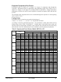
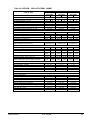
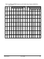
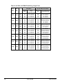
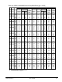
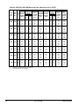
Evaporator Temperature Drop Factors
Performance tables are based on a 10 degree F (5 degree C) temperature drop through the
evaporator. Adjustment factors for applications with temperature ranges from 6 degree F to 16
degree F (3.3 degree C to 8.9 degree C) are found in Table 12 and Table 13. Ranges outside these
temperatures can affect the control system's capability to maintain acceptable control and must not
be used.
The maximum water temperature that can be circulated through the evaporator in a non-operating
mode is 100°F (37.8°C).
Fouling Factor
Performance tables are based on water with a fouling factor of:
2
0.0001 ft × hr × ° F / BTU
or
2
(0.0176m × °C / kW ) per ARI 550/590-98.
As fouling is increased, performance decreases. For performance at other than 0.0001 (0.0176)
fouling factor, refer to Table 12 and Table 13. Foreign matter in the chilled water system will
adversely affect the heat transfer capability of the evaporator and could increase the pressure drop
and reduce the water flow. Maintain proper water treatment to provide optimum unit operation.
Table 12, Capacity and Power Derates, Models AGZ 026 to 070
Altitude
Sea
Level
2000 feet
4000 feet
6000 feet
8000 feet
IOMM ACZ/AGZ-3
Fouling Factor
Chilled Water
Delta T
0.0001 (0.0176)
0.00025 (0.044)
0.00075 (0.132)
0.00175 (0.308)
°F
°C
Cap.
Power
Cap.
Power
Cap.
Power
Cap.
Power
6
3.3
0.978
0.993
0.975
0.991
0.963
0.987
0.940
0.980
8
4.4
0.989
0.996
0.986
0.994
0.973
0.990
0.950
0.983
10
5.6
1.000
1.000
0.996
0.999
0.984
0.994
0.961
0.987
12
6.7
1.009
1.003
1.005
1.001
0.993
0.997
0.969
0.990
14
7.7
1.018
1.004
1.014
1.003
1.002
0.999
0.978
0.991
16
8.9
1.025
1.007
1.021
1.006
1.009
1.001
0.985
0.994
6
3.3
0.977
1.001
0.973
1.000
0.961
0.996
0.938
0.989
8
4.4
0.987
1.006
0.984
1.004
0.971
1.000
0.948
0.993
10
5.6
0.998
1.009
0.995
1.007
0.982
1.003
0.959
0.996
12
6.7
1.007
1.011
1.004
1.010
0.991
1.006
0.967
0.998
14
7.7
1.014
1.014
1.011
1.013
0.998
1.009
0.974
1.001
16
8.9
1.022
1.016
1.018
1.014
1.005
1.010
0.981
1.003
6
3.3
0.973
1.011
0.970
1.010
0.957
1.006
0.935
0.998
8
4.4
0.984
1.014
0.980
1.013
0.968
1.009
0.945
1.001
10
5.6
0.995
1.019
0.991
1.017
0.979
1.013
0.955
1.005
12
6.7
1.004
1.021
1.000
1.020
0.987
1.016
0.964
1.008
14
7.7
1.011
1.024
1.007
1.023
0.994
1.018
0.971
1.011
16
8.9
1.018
1.027
1.014
1.026
1.002
1.021
0.978
1.014
6
3.3
0.969
1.021
0.966
1.020
0.954
1.016
0.931
1.008
8
4.4
0.980
1.026
0.977
1.024
0.964
1.020
0.942
1.013
10
5.6
0.989
1.029
0.986
1.027
0.973
1.023
0.950
1.015
12
6.7
0.998
1.033
0.995
1.031
0.982
1.027
0.959
1.020
14
7.7
1.007
1.036
1.004
1.034
0.991
1.030
0.967
1.022
16
8.9
1.014
1.037
1.011
1.036
0.998
1.031
0.974
1.024
6
3.3
0.964
1.034
0.961
1.033
0.949
1.028
0.926
1.021
8
4.4
0.975
1.037
0.971
1.036
0.959
1.031
0.936
1.024
10
5.6
0.986
1.041
0.982
1.040
0.970
1.036
0.947
1.028
12
6.7
0.995
1.044
0.991
1.043
0.979
1.038
0.955
1.031
14
7.7
1.002
1.047
0.998
1.046
0.986
1.041
0.962
1.034
16
8.9
1.009
1.050
1.005
1.049
0.993
1.044
0.969
1.037
ACZ / AGZ-BM
19
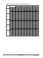
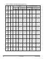
Table 13, Capacity and Power Derates, Models AGZ 075 to 130
Altitude
Sea
Level
2000 feet
4000 feet
6000 feet
8000 feet
20
Fouling Factor
Chilled Water
Delta T
0.0001 (0.0176)
0.00025 (0.044)
0.00075 (0.132)
0.00175 (0.308)
°F
°C
Cap.
Power
Cap.
Power
Cap.
Power
Cap.
Power
6
3.3
0.990
0.997
0.976
0.994
0.937
0.983
0.868
0.964
8
4.4
0.994
0.998
0.981
0.995
0.942
0.984
0.872
0.965
10
5.6
1.000
1.000
0.987
0.996
0.947
0.986
0.877
0.967
12
6.7
1.005
1.001
0.991
0.997
0.951
0.986
0.881
0.968
14
7.7
1.009
1.002
0.995
0.998
0.955
0.987
0.884
0.968
16
8.9
1.013
1.004
1.000
1.000
0.960
0.989
0.889
0.970
6
3.3
0.987
1.005
0.974
1.002
0.934
0.991
0.865
0.972
8
4.4
0.992
1.006
0.979
1.003
0.940
0.992
0.870
0.973
10
5.6
0.997
1.008
0.984
1.004
0.944
0.994
0.875
0.975
12
6.7
1.002
1.009
0.989
1.005
0.949
0.994
0.879
0.975
14
7.7
1.007
1.011
0.993
1.007
0.953
0.996
0.883
0.977
16
8.9
1.011
1.012
0.998
1.008
0.958
0.997
0.887
0.978
6
3.3
0.985
1.014
0.972
1.010
0.933
0.999
0.864
0.980
8
4.4
0.991
1.015
0.977
1.012
0.938
1.001
0.869
0.981
10
5.6
0.995
1.016
0.982
1.013
0.943
1.002
0.873
0.982
12
6.7
1.000
1.018
0.987
1.014
0.947
1.003
0.877
0.984
14
6.8
1.005
1.019
0.991
1.015
0.951
1.004
0.881
0.985
16
8.9
1.009
1.021
0.995
1.017
0.955
1.006
0.884
0.987
6
3.3
0.982
1.023
0.969
1.020
0.930
1.009
0.861
0.989
8
4.4
0.988
1.025
0.975
1.022
0.935
1.010
0.866
0.991
10
5.6
0.992
1.026
0.979
1.022
0.940
1.011
0.870
0.992
12
6.7
0.997
1.028
0.984
1.024
0.944
1.013
0.875
0.994
14
7.7
1.002
1.029
0.989
1.025
0.949
1.014
0.879
0.995
16
8.9
1.006
1.031
0.992
1.027
0.952
1.016
0.882
0.996
6
3.3
0.979
1.034
0.966
1.031
0.927
1.019
0.859
1.000
8
4.4
0.984
1.036
0.971
1.032
0.932
1.021
0.863
1.002
10
5.6
0.990
1.037
0.976
1.033
0.937
1.022
0.868
1.002
12
6.7
0.993
1.039
0.980
1.035
0.941
1.024
0.871
1.004
14
7.7
0.998
1.041
0.985
1.037
0.945
1.026
0.875
1.006
16
8.9
1.003
1.041
0.990
1.038
0.950
1.026
0.879
1.007
ACZ / AGZ-BM
IOMM ACZ/AGZ-3
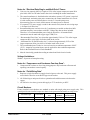
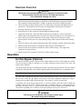
ACZ Compressor Staging
Temperature control for the evaporator is provided by the installer through a field supplied and
wired temperature controller. The field supplied staging signals are field wired to the Microtech II
controller that correspondingly activates and deactivates the scroll compressors. The field supplied
temperature controller is required to close normally-open 24 volt contacts on a demand for cooling.
These closure signals are field wired to the terminal strip (TB3) in the condensing unit. Refer to the
field wiring diagram (page 49) for details. The following control staging is required:
Condensing Unit Model
ACZ-030B through 110B
ACZ-120B through 155B
Number of
Capacity Steps
4
6
Number of Required
Contact Closure Signals
4
6
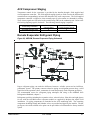
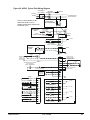
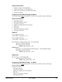
Remote Evaporator Refrigerant Piping
Figure 20, AGZ-BM, Remote Evaporator Piping Schematic
Proper refrigerant piping can make the difference between a reliable system and an inefficient,
problematic system. The primary concerns related to piping are refrigerant pressure drop, a solid
liquid feed to the expansion valves, continuous oil return and properly sized refrigerant specialties.
The recommended source for refrigerant piping techniques and sizing is the ASHRAE 2002
Refrigeration Handbook, chapter 2.
Refrigerant specialties including the expansion valves, solenoid valves, filter-drier and sight glasses
for use with the AGZ-BM remote evaporator models are supplied by McQuay but require field
installation. No piping components are furnished on the ACZ condensing units. The remaining
components including fittings and Schrader valves are provided and piped by the installer. The hot
gas bypass valve with solenoid valve option can be provided as a field-installed or factory installed
option.
IOMM ACZ/AGZ-3
ACZ / AGZ-BM
21
The condensing unit section has a liquid line shut-off valve and a suction shut-off valve provided as
standard. A holding charge of R-22 is provided for the evaporator (AGZ-BM) and the outdoor
section. The installer must properly evacuate the piping system and provide the operating charge of
R22. Refer to the piping schematic drawing on page 21 for additional details.
Although conflicting piping recommendations can be found in different sources, McQuay offers the
following recommendations for these controversial issues.
The use of double risers for vertical gas risers is generally not required and should be used only as a
last resort to maintain the minimum refrigerant flow to carry oil up the vertical risers. Slightly
downsizing the vertical riser is a preferable option to providing double risers.
Slope the refrigerant lines 1” per 10 feet of horizontal run in the direction of refrigerant flow to
assist oil return.
Resist using hot gas bypass for applications when operation in ambient temperature below 40
degrees is expected. This recommendation helps to maintain adequate condensing pressures and
liquid refrigerant at the expansion valve when condenser capacities are at their maximum.
Pressure drops in the refrigerant lines should be maintained at or below the ASHRAE
recommendations and line lengths should be made as short as possible. Exceeding these
recommendations will decrease performance and could impact reliability.
Small traps should be provided at the base of each major vertical gas riser to assist in the collection
of oil. If vertical risers exceed more than 25 feet, install a small trap at the midpoint and at a
maximum of 20 foot intervals.
Use caution in sizing the liquid line in applications where the evaporator is above the outdoor
section. The weight of the liquid refrigerant in the vertical column will decrease the pressure at the
top of the riser (approximately 0.5 psi per foot of vertical rise) allowing some of the refrigerant to
flash to a gas. Adequate refrigerant subcooling is needed at the outdoor section to prevent large
volumes of refrigerant gas at the expansion valve.
The piping systems should always extend above the highest component in the refrigeration system
before dropping down to make the final refrigerant connections to components. This practice will
hinder the draining of condensed refrigerant to the lower component when normal shutdown
procedures do not occur (such as a power failure).
Pumpdown
The pumpdown capacity of ACZ/AGZ units is given in the Physical Data Tables. Care should be
exercised to include all equipment and lines when calculating the system charge relative to the unit’s
pumpdown capacity. The AGZ-BM remote evaporators have an insignificant operating charge.
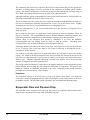
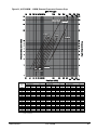
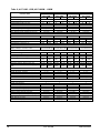
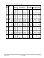
Evaporator Flow and Pressure Drop
The AGZ-BM remote evaporator flow rate must fall between the minimum and maximum values
shown in the evaporator pressure drop table on the following page.
22
ACZ / AGZ-BM
IOMM ACZ/AGZ-3
Figure 21, AGZ 026BM – 130BM, Remote Evaporator Pressure Drop
075-085-090
120-130
026-030
035
040
050
045
AGZ Unit
Model
026B
030B
035B
040B
045B
050B
055B
060B
065B
070B
075B
085B
090B
100B
110B
120B
130B
060
100-110
065-070
055
Minimum
Inch-Pound
S.I.
gpm
DP ft.
lps
DP kpa
41
1.6
2.6
4.7
45
1.9
2.9
5.7
50
1.9
3.1
5.6
58
1.9
3.6
5.7
64
1.8
4.0
5.4
71
1.8
4.4
5.4
78
1.8
4.9
5.3
86
1.7
5.4
5.2
92
1.6
5.8
4.9
98
1.9
6.2
5.6
111
5.6
7.0
16.5
119
6.3
7.5
18.9
128
7.2
8.1
21.4
146
2.6
9.2
7.7
161
3.1
10.2
9.2
180
3.5
11.3
10.4
194
4.1
12.2
12.1
Nominal
Inch-Pound
S.I.
gpm
DP ft.
lps
DP kpa
65
3.9
4.1
11.6
72
4.7
4.6
14.1
80
4.6
5.0
13.8
92
4.7
5.8
14.0
102
4.5
6.4
13.4
113
4.5
7.1
13.3
125
4.4
7.9
13.0
137
4.3
8.6
12.8
147
4.1
9.3
12.1
157
4.6
9.9
13.7
177
12.5
11.2
37.4
191
14.3
12.1
42.7
205
16.2
12.9
48.4
234
6.1
14.8
18.2
258
7.3
16.3
21.7
288
8.9
18.1
26.5
311
10.4
19.6
30.9
Maximum
Inch-Pound
S.I.
gpm
DP ft.
lps
DP kpa
109
10.4
6.9
30.9
121
12.7
7.6
37.8
133
12.4
8.4
36.9
154
12.6
9.7
37.5
170
12.1
10.7
35.9
188
12.0
11.9
35.7
209
11.7
13.2
34.8
228
11.5
14.4
34.2
246
10.9
15.5
32.5
262
12.3
16.5
36.8
295
30.4
18.6
90.7
318
34.8
20.1
103.6
342
39.4
21.6
117.3
390
15.5
24.6
46.2
430
18.5
27.1
55.1
479
24.6
30.2
73.4
518
28.7
32.7
85.6
NOTE: Minimum and maximum flows are established to ensure the Delta-T for each unit size falls within the 6 - 16°F range for
proper unit control.
IOMM ACZ/AGZ-3
ACZ / AGZ-BM
23
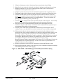
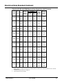
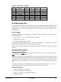
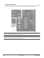
Wind Baffles and Hail Guards
Wind Baffles/Hail Guards are a field-installed option that is used to stabilize unit operation in high wind
areas and to assist in operation at low ambient temperatures. Figure 22 is a sketch of a typical panel
assembly on an ACZ/AGZ unit. The actual number of panels and parts will vary by model size. The
parts are shown in the table below and referenced by balloon numbers.
Figure 22, Installation Sequence
Rib Attachment (First)
RIB FLANGES ON THE END
MUST POINT TO CENTER
OF COIL TO HAVE A FINISHED
LOOK. INTERIOR RIB FLANGES
CAN POINT IN ANY DIRECTION.
UNIT VERTICAL COIL
ATTACH ALL RIBS TO
COIL VERTICAL CHANNELS.
Front Panel Attachment (Second)
PLACE FRONT "A" AND
FASTEN TO BOTH SIDES
E
UNIT VERTICAL COIL
D
C
B
2
PLACE FRONT "B" BY LAPPING
OVER "A" AND REPEAT
ATTACHMENT PROCEDURE.
A
1
3
Top Panel Attachment (Last)
E
ATTACH TOP "A" AT HORIZONTAL COIL CHANNEL FIRST.
THIS WILL SQUARE THE PANEL.
OVERLAP THE FRONT PANEL FLANGE.
UNIT VERTICAL COIL
D
C
B
A
ATTACH LEFT SIDE SECOND.
OVERLAP PANEL "B" OVER PANEL "A"
AND REPEAT ATTACHMENT PROCEDURE.
24
ACZ / AGZ-BM
IOMM ACZ/AGZ-3
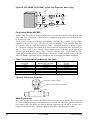
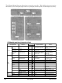
Table 14, Packing List
Description
Vertical Support Rib
Top Cover
Front Panel
¼ - 20 x ½” Screw (Place in Poly Bag)
Part Number
074758501
330409401
330409501
046093807
Bubble Number
1
2
3
Figure 23, Components
TOP
REAR (AGAINST UNIT)
VERTICAL SUPPORT RIB
TOP COVER
FRONT PANEL
Top Panel, Install Last
Overlap the Front panel
Front Panel, Install Second
Rib, Install First
IOMM ACZ/AGZ-3
ACZ / AGZ-BM
25
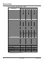
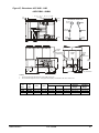
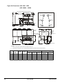
Physical Data
Table 15, ACZ 030B - 040B, AGZ 026BM – 035BM
PHYSICAL DATA
BASIC DATA
ACZ 030B,
AGZ 026BM
Ckt.1
Number Of Refrigerant Circuits
MODEL NUMBER
ACZ 035B
AGZ 030BM
Ckt.2
Ckt.1
2
ACZ 040B
AGZ 035BM
Ckt.2
Ckt.1
Ckt.2
2
2
Unit Operating Charge, R-22, Lbs.
22
22
22
27
27
27
Unit Operating Charge, R-22, kg
10
10
10
12
12
12
Cabinet Dimensions, LxWxH, In.
94.4 x 88.0 x 100.4
Cabinet Dimensions, LxWxH, (mm)
2398 x 2235 x 2550 2398 x 2235 x 2550 2398 x 2235 x 2550
94.4 x 88.0 x 100.4
94.4 x 88.0 x 100.4
Unit Operating Weight, Lb (kg)
3600 (1634)
3600 (1634)
3600 (1634)
Unit Shipping Weight, Lb (kg)
Add'l. Weight If Copper Finned Coils, Lb.
(kg)
3550 (1612)
3550 (1612)
3550 (1612)
284 (129)
284 (129)
284 (129)
Tandem Scrolls
Tandem Scrolls
Tandem Scrolls
COMPRESSORS
Type
Nominal tonnage of each Compressor
Number Of Compressors per Circuit
7.5
7.5
7.5
9.0
9.0
9.0
2
2
2
2
2
2
Oil Charge Per Compressor, Oz.
140
140
140
140
140
140
Oil Charge Per Compressor, (g)
(496)
(496)
(496)
(496)
(496)
(496)
CAPACITY REDUCTION STEPS - PERCENT OF COMPRESSOR DISPLACEMENT
Staging, 4 Stages, Circuit #1 in Lead
0-25-50-75-100
0-23-50-73-100
0-25-50-75-100
Staging, 4 Stages, Circuit #2 in Lead
0-25-50-75-100
0-27-50-77-100
0-25-50-75-100
CONDENSERS - HIGH EFFICIENCY FIN AND TUBE TYPE WITH INTEGRAL SUBCOOLING
Coil Face Area Sq. Ft.
26.3
26.3
26.3
26.3
26.3
Coil Face Area, (M2)
2.4
2.4
2.4
2.4
2.4
2.4
Fins Per Inch x Rows Deep
50x75.6
1270 x
1920
16 x 3
50x75.6
1270 x
1920
16 x 3
50x75.6
1270 x
1920
16 x 3
50x75.6
1270 x
1920
16 x 3
50x75.6
1270 x
1920
16 x 3
50x75.6
1270 x
1920
16 x 3
Pumpdown Capacity, 90% Full Lbs. (kg)
Maximum Relief Valve Pressure Setting,
psig (kPa)
49 (22)
450
(3103)
49 (22)
450
(3103)
49 (22)
450
(3103)
49 (22)
450
(3103)
49 (22)
450
(3103)
49 (22)
450
(3103)
Finned Height x Finned Length, In.
Finned Height x Finned Length, (mm)
26.3
CONDENSER FANS - DIRECT DRIVE PROPELLER TYPE
Number Of Fans - Fan Diameter, In. (mm)
Number Of Motors - HP (kW) (2)
Fan And Motor RPM, 60Hz
60 Hz Fan Tip Speed, FPM (M/Sec)
60 Hz Total Unit Airflow, CFM (M3/sec)
4 – 30 (762)
4 – 30 (762)
4 – 30 (762)
4 – 1.0
4 – 1.0
4 – 1.0
1140
1140
1140
8950 (4224)
8950 (4224)
8950 (4224)
24,316 (11,478)
24,316 (11,478)
24,316 (11,478)
1
2
5.0 (18.9)
363 (2503)
450 (3102)
3 (76)
Field
Field
1
2
5.7 (21.4)
363 (2503)
450 (3102)
3 (76)
Field
Field
REMOTE EVAPORATOR - BRAZED PLATE (AGZ-BM ONLY)
Number of Evaporators
1
Number of Refrigerant Circuits
2
Water Volume, Gallons, (L)
4.3 (16.4)
Maximum Water Pressure, psig (kPa)
363 (2503)
Max. Refrig. Working Pressure, psig (kPa)
450 (3102)
Water Inlet / Outlet Victaulic Conn. In. (mm)
3 (76)
Drain - NPT int., In. (mm)
Field
Vent - NPT int., In. (mm)
Field
NOTES:
1.
Nominal capacity based on 95°F ambient air and 50°F SST.
2.
Except for 380V/60 & 575V/60, HP = 2.0
26
ACZ / AGZ-BM
IOMM ACZ/AGZ-3
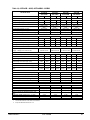
Table 16, ACZ 045B - 060B, AGZ 040BM – 055BM
PHYSICAL DATA
MODEL NUMBER
ACZ 050B
ACZ 055B
AGZ 045BM
AGZ 050BM
ACZ 045B
AGZ 040BM
BASIC DATA
Ckt.1
Number Of Refrigerant Circuits
Ckt.1
Ckt.2
2
Ckt.1
Ckt.2
Ckt.1
2
ACZ 060B
AGZ 055BM
Ckt.2
2
Ckt.2
2
Unit Operating Charge, R-22, lbs.
31
31
37
37
37
37
44
44
Unit Operating Charge, R-22, kg
14
14
17
17
17
17
20
20
Cabinet Dimensions, LxWxH, in.
Cabinet Dimensions, LxWxH, (mm)
Unit Operating Weight, Lbs. (kg)
94.4 x 88.0 x 100.4 94.4 x 88.0 x 100.4 94.4 x 88.0 x 100.4 94.4 x 88.0 x 100.4
2398 x 2235 x
2398 x 2235 x
2398 x 2235 x
2398 x 2235 x
2250
2250
2250
2250
3610 (1639)
3650 (1657)
3800 (1725)
3850 (1748)
Unit Shipping Weight, Lbs. (kg)
3550 (1612)
3590 (1630)
3730 (1693)
3780 (1716)
288 (130)
288 (130)
476 (130)
476 (130)
Type
Tandem Scrolls
Tandem Scrolls
Tandem Scrolls
Tandem Scrolls
Nominal tonnage of each Compressor
10.0
10.0
13.0
13.0
Add'l. Weight If Copper Finned Coils, lbs. (kg)
COMPRESSORS
Number Of Compressors per Circuit
10.0
13.0
13.0
15.0
2
2
2
2
2
2
2
2
Oil Charge Per Compressor, oz.
140
140
140
140
140
140
140
140
Oil Charge Per Compressor, (g)
(496)
(496)
(496)
(496)
(496)
(496)
(496)
(496)
CAPACITY REDUCTION STEPS - PERCENT OF COMPRESSOR DISPLACEMENT
Staging, 4 Stages, Circuit #1 in Lead
Staging, 4 Stages, Circuit #2 in Lead
0-25-50-75-100
0-25-50-75-100
0-22-50-46-100
0-28-50-85-100
0-25-50-75-100
0-25-50-75-100
0-25-50-75-100
0-25-50-75-100
CONDENSERS - HIGH EFFICIENCY FIN AND TUBE TYPE WITH INTEGRAL SUBCOOLING
Coil Face Area, sq. ft. (Note 1)
26.3
26.3
44.1
44.1
44.1
44.1
44.1
Coil Face Area (sq. M)
2.4
2.4
4.1
4.1
4.1
4.1
4.1
4.1
42x75.6
1067 x
1920
16 x 2
42x75.6
1067 x
1920
16 x 3
42x75.6
1067 x
1920
16 x 3
60(27)
450
(3103)
82 (37)
450
(3103)
82 (37)
450
(3103)
Finned Height x Finned Length, in.
Fins Per Inch x Rows Deep
50x75.6
1270 x
1920
16 x 3
50x75.6 42x75.6 42x75.6 42x75.6
1270 x 1067 x 1067 x 1067 x
1920
1920
1920
1920
16 x 3
16 x 2
16 x 2
16 x 2
Pumpdown Capacity, 90% Full Lbs. (kg)
Maximum Relief Valve Pressure Setting, psig
(kPa)
49 (22)
450
(3103)
49 (22)
450
(3103)
Finned Height x Finned Length, (mm)
60(27)
450
(3103)
60(27)
450
(3103)
60(27)
450
(3103)
44.1
CONDENSER FANS - DIRECT DRIVE PROPELLER TYPE
Number Of Fans - Fan Diameter, in. (mm)
Number Of Motors - HP (kW) (Note 2))
Fan And Motor RPM, 60Hz
60 Hz Fan Tip Speed, FPM (m/sec)
60 Hz Total Unit Airflow, CFM (m3/sec)
4 – 30 (762)
4 – 30 (762)
4 – 30 (762)
4 – 30 (762)
4 – 1.5
4 – 1.5
4 – 1.5
4 – 1.5
1140
1140
1140
1140
8950 (4224)
8950 (4224)
8950 (4224)
8950 (4224)
39,600 (18,692)
39,600 (18,692)
37,228 (17,572)
37,228 (17,572)
1
2
7.2 (27.3)
363 (2503)
1
2
8.1 (30.7)
363 (2503)
1
2
9.2 (34.9)
363 (2503)
450 (3102)
450 (3102)
450 (3102)
3 (76)
Field
Field
3 (76)
Field
Field
3 (76)
Field
Field
REMOTE EVAPORATOR - BRAZED PLATE (AGZ-BM ONLY)
Number of Evaporators
1
Number of Refrigerant Circuits
2
Water Volume, Gallons, (L)
6.3 (23.9)
Maximum Water Pressure, psig (kPa)
363 (2503)
Maximum Refrigerant Working Pressure, psig
450 (3102)
(kPa)
Water Inlet / Outlet Victaulic Conn., in. (mm)
3 (76)
Drain - NPT int., in. (mm)
Field
Vent - NPT int., in. (mm)
Field
NOTES:
1.
The AGZ 040 condenser is the same as the AGZ 045.
2.
Except for 380V/60 & 575V/60, HP = 2.0
IOMM ACZ/AGZ-3
ACZ / AGZ-BM
27
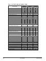
Table 17, ACZ 065B - 080B, AGZ 060BM – 070BM
PHYSICAL DATA
ACZ 065B
AGZ 060BM
BASIC DATA
Ckt.1
Number Of Refrigerant Circuits
Ckt.2
MODEL NUMBER
ACZ 070B
AGZ 065BM
Ckt.1
2
Ckt.2
ACZ 080B
AGZ 070BM
Ckt.1
2
Ckt.2
2
Unit Operating Charge, R-22, lbs.
44
44
50
57
57
57
Unit Operating Charge, R-22, kg
20
20
23
26
26
26
Cabinet Dimensions, LxWxH, in.
94.4 x 88.0 x 100.4 94.4 x 88.0 x 100.4 94.4 x 88.0 x 100.4
2398 x 2235 x
2398 x 2235 x
2398 x 2235 x
2550
2550
2550
4040 (1834)
4070 (1848)
4180 (1898)
Cabinet Dimensions, LxWxH, (mm)
Unit Operating Weight, Lbs. (kg)
Unit Shipping Weight, Lbs. (kg)
3820 (1734)
3970 (1802)
4080 (1852)
476 (216)
568 (258)
568 (258)
Type
Tandem Scrolls
Tandem Scrolls
Nominal tonnage of each Compressor
15.0
15.0
Add'l Weight If Copper Finned Coils, lbs. (kg)
COMPRESSORS
Number Of Compressors per Circuit
15.0
Tandem Scrolls
15 / 20
15 / 20
15 / 20
2
2
2
2
2
2
Oil Charge Per Compressor, oz.
140
140
140
140 /148 140 /148 140 /148
Oil Charge Per Compressor, (g)
(496)
(496)
(496)
496/ 525 496/ 525 496/ 525
CAPACITY REDUCTION STEPS - PERCENT OF COMPRESSOR DISPLACEMENT
Staging, 4 Stages, Circuit #1 in Lead
Staging, 4 Stages, Circuit #2 in Lead
0-25-50-75-100
0-25-50-75-100
0-23-46-77-100
0-31-46-69-100
0-25-50-75-100
0-25-50-75-100
CONDENSERS - HIGH EFFICIENCY FIN AND TUBE TYPE WITH INTEGRAL SUBCOOLING
Coil Face Area, sq. ft.
44.1
44.1
52.6
52.6
52.6
52.6
Coil Face Area, (m2)
4.1
4.1
4.9
4.9
4.9
4.9
Finned Height x Finned Length, in.
42x75.6
1067 x
1920
16 x 3
Finned Height x Finned Length, (mm)
Fins Per Inch x Rows Deep
Pumpdown Capacity, 90% Full Lbs. (kg)
Maximum Relief Valve Pressure Setting, psig
(kPa)
82 (37
450
(3103)
42x75.6 100x75.6 100x75.6 100x75.6 100x75.6
1067 x 2540 x 2540 x 2540 x
2540 x
1920
1920
1920
1920
1920
16 x 3
16 x 3
16 x 3
16 x 3
16 x 3
82 (37
450
(3103)
98 (44
450
(3103)
98 (44
450
(3103)
98 (44
450
(3103)
98 (44
450
(3103)
CONDENSER FANS - DIRECT DRIVE PROPELLER TYPE
Number Of Fans - Fan Diameter, in. (mm)
Number Of Motors - HP (kW) (1)
Fan And Motor RPM, 60Hz
60 Hz Fan Tip Speed, FPM (m/sec)
60 Hz Total Unit Airflow, CFM (m3/sec)
4 – 30 (762)
4 – 30 (762)
4 – 30 (762)
4 – 1.5
4 – 2.0
4 – 2.0
1140
1140
1140
8950 (4224)
8950 (4224)
8950 (4224)
37,228 (17,572
43,452 (20,510)
43,452 (20,510)
1
2
11.2 (42.5)
363 (2503)
450 (3102)
3 (76)
Field
Field
1
2
11.2 (42.5)
363 (2503)
450 (3102)
3 (76)
Field
Field
REMOTE EVAPORATOR - BRAZED PLATE (AGZ-BM ONLY)
Number of Evaporators
1
Number of Refrigerant Circuits
2
Water Volume, Gallons, (L)
9.2 (34.9)
Maximum Water Pressure, psig (kPa)
363 (2503)
Maximum Refrigerant Working Press., psig (kPa)
450 (3102)
Water Inlet / Outlet Victaulic Conn., in. (mm)
3 (76)
Drain - NPT int, in. (mm)
Field
Vent - NPT int, in. (mm)
Field
NOTE: Except for 380V/60 & 575V/60, HP = 2.0
28
ACZ / AGZ-BM
IOMM ACZ/AGZ-3
Table 18, ACZ 090B - 110B, AGZ 075BM – 090BM
PHYSICAL DATA
ACZ 090B
AGZ 075BM
Ckt.1
Ckt.2
2
56
56
25
25
134.9 x 88.0 x 100.4
3426 x 2235 x 2550
5630 (2556)
5510 (2502)
870 (395)
MODEL NUMBER
ACZ 100B
AGZ 085BM
Ckt.1
Ckt.2
2
56
66
25
30
134.9 x 88.0 x 100.4
3426 x 2235 x 2550
5790 (2629)
5670 (2574)
870 (395)
ACZ 110B
AGZ 090BM
Ckt.1
Ckt.2
2
66
66
30
30
134.9 x 88.0 x 100.4
3426 x 2235 x 2550
5950 (2701)
5830 (2647)
870 (395)
1
2
14.0 x 5.2
356 x 1585
25 (95)
152 (1047)
300 (2066)
5 (127)
0.5 (12.7)
0.5 (12.7)
1
2
14.0 x 5.2
356 x 1585
25 (95)
152 (1047)
300 (2066)
5 (127)
0.5 (12.7)
0.5 (12.7)
BASIC DATA
Number Of Refrigerant Circuits
Unit Operating Charge, R-22, lbs.
Unit Operating Charge, R-22, (kg)
Cabinet Dimensions, LxWxH, in.
Cabinet Dimensions, LxWxH, (mm)
Unit Operating Weight, Lbs. (kg)
Unit Shipping Weight, Lbs. (kg)
Add'l Weight If Copper Finned Coils, lbs. (kg)
COMPRESSORS
Type
Tandem Scrolls
Tandem Scrolls
Tandem Scrolls
Nominal tonnage of each Compressor
20.0
20.0
20.0
25.0
25.0
25.0
Number Of Compressors per Circuit
2
2
2
2
2
2
Oil Charge Per Compressor, oz.
148
148
148
200
200
200
Oil Charge Per Compressor, (g)
(525)
(525)
(525)
(709)
(709)
(709)
CAPACITY REDUCTION STEPS - PERCENT OF COMPRESSOR DISPLACEMENT
Staging, 4 Stages, Circuit #1 in Lead
0-25-50-75-100
0-22-50-72-100
0-25-50-75-100
Staging, 4 Stages, Circuit #2 in Lead
0-25-50-75-100
0-28-50-78-100
0-25-50-75-100
CONDENSERS - HIGH EFFICIENCY FIN AND TUBE TYPE WITH INTEGRAL SUBCOOLING
Coil Face Area, sq. ft.
78.8
78.8
78.8
78.8
78.8
78.8
Coil Face Area, (m2)
7.3
7.3
7.3
7.3
7.3
7.3
Finned Height x Finned Length, in.
50 x113.4 50 x113.4 50 x113.4 50 x113.4 50 x113.4 50 x113.4
1270 x
1270 x
1270 x
1270 x
1270 x
1270 x
Finned Height x Finned Length, (mm)
2880
2880
2880
2880
2880
2880
Fins Per Inch x Rows Deep
16 x 3
16 x 3
16 x 3
16 x 3
16 x 3
16 x 3
Pumpdown Capacity, 90% Full Lbs. (kg)
147 (67) 147 (67) 147 (67) 147 (67) 147 (67) 147 (67)
450
450
450
450
450
450
Maximum Relief Valve Pressure Setting, psig (kPa)
(3103)
(3103)
(3103)
(3103)
(3103)
(3103)
CONDENSER FANS - DIRECT DRIVE PROPELLER TYPE
Number Of Fans - Fan Diameter, in. (mm)
6 – 30 (762)
6 – 30 (762)
6 – 30 (762)
Number Of Motors - HP (kW)
6 – 2.0
6 – 2.0
6 – 2.0
Fan And Motor RPM, 60Hz
1140
1140
1140
60 Hz Fan Tip Speed, FPM (m/sec)
8950 (4224)
8950 (4224)
8950 (4224)
60 Hz Total Unit Airflow, CFM (m3/sec)
65,178 (30,765)
65,178 (30,765)
65,178 (30,765)
REMOTE EVAPORATOR - SHELL AND TUBE (AGZ-BM ONLY)
Number of Evaporators
1
Number of Refrigerant Circuits
2
Diameter, in. - Length, ft.
14.0 x 5.2
Diameter, (mm) – Length, (mm)
356 x 1585
Water Volume, Gallons, (L)
25 (95)
Maximum Water Pressure, psig (kPa)
152 (1047)
Maximum Refrigerant Working Pressure, psig (kPa)
300 (2066)
Water Inlet / Outlet Victaulic Connections, in. (mm)
5 (127)
Drain - NPT int, in. (mm)
0.5 (12.7)
Vent - NPT int, in. (mm)
0.5 (12.7)
IOMM ACZ/AGZ-3
ACZ / AGZ-BM
29
Table 19, ACZ 120B - 155B, AGZ 100BM – 130BM
PHYSICAL DATA
ACZ 120B
AGZ 100BM
Ckt.1
Ckt.2
2
72
82
33
37
173.1 x 88.0 x 100.4
4397 x 2235 x 2550
6970 (3164
6820 (3096)
1155 (524)
MODEL NUMBER
ACZ 130B
ACZ 140B
AGZ 110BM
AGZ 120BM
Ckt.1
Ckt.2
Ckt.1
Ckt.2
2
2
82
82
82
99
37
37
37
45
173.1 x 88.0 x 100.4 173.1 x 88.0 x 100.4
4397 x 2235 x 2550 4397 x 2235 x 2550
7230 (3282)
7480 (3396)
7080 (3214)
7360 (3341)
1155 (524)
1155 (524)
BASIC DATA
Number Of Refrigerant Circuits
Unit Operating Charge, R-22, lbs.
Unit Operating Charge, R-22, (kg)
Cabinet Dimensions, LxWxH, in.
Cabinet Dimensions, LxWxH, (mm)
Unit Operating Weight, Lbs. (kg)
Unit Shipping Weight, Lbs. (kg)
Add'l. Weight If Copper Finned Coils, lbs. (kg)
COMPRESSORS
Type
Trio Scrolls
Trio Scrolls
Nominal tonnage of each Compressor
15.0
20.0
20.0
20.0
Number Of Compressors per Circuit
3
3
3
3
Oil Charge Per Compressor, oz.
140
148
148
148
Oil Charge Per Compressor, (g)
(496)
(525)
(525)
(525)
CAPACITY REDUCTION STEPS - PERCENT OF COMPRESSOR DISPLACEMENT
Staging, 6 Stages, Circuit #1 in Lead
0-14-33-48-67-81-100 0-17-33-50-67-83-100
Staging, 6 Stages, Circuit #2 in Lead
0-19-33-52-67-86-100 0-17-33-50-67-83-100
CONDENSERS - HIGH EFFICIENCY FIN AND TUBE TYPE WITH INTEGRAL SUBCOOLING
Coil Face Area, sq. ft.
105.3
105.3
105.3
105.3
Coil Face Area, (m2)
9.8
9.8
9.8
9.8
Finned Height x Finned Length, in.
50 x151.6 50 x151.6 50 x151.6 50 x151.6
1270 x
1270 x
1270 x
1270 x
Finned Height x Finned Length, (mm)
3851
3851
3851
3851
Fins Per Inch x Rows Deep
16 x 3
16 x 3
16 x 3
16 x 3
Pumpdown Capacity, 90% Full Lbs. (kg)
196 (89) 196 (89) 196 (89) 196 (89)
Maximum Relief Valve Pressure Setting, psig
450
450
450
450
(kPa)
(3103)
(3103)
(3103)
(3103)
CONDENSER FANS - DIRECT DRIVE PROPELLER TYPE
Number Of Fans - Fan Diameter, in. (mm)
8 – 30 (762)
8 – 30 (762)
Number Of Motors - HP (kW)
8 – 2.0
8 – 2.0
Fan And Motor RPM, 60Hz
1140
1140
60 Hz Fan Tip Speed, FPM (m/sec)
8950 (4224)
8950 (4224)
60 Hz Total Unit Airflow, CFM (m3/sec)
86,904 (41,020)
86,904 (41,020)
REMOTE EVAPORATOR - SHELL AND TUBE (AGZ-BM ONLY)
Number of Evaporators
1
Number of Refrigerant Circuits
2
Diameter, in. - Length, ft.
12.8 x 7.9
Diameter, (mm) – Length, (mm)
324 x 2408
Water Volume, Gallons, (L)
34 (127)
Maximum Water Pressure, psig (kPa)
152 (1047)
Maximum Refrigerant Working Press., psig (kPa)
300 (2066)
Water Inlet / Outlet Victaulic Conn., in. (mm)
5 (127)
Drain - NPT int., in. (mm)
0.5 (12.7)
Vent - NPT int., in. (mm)
0.5 (12.7)
30
ACZ / AGZ-BM
1
2
12.8 x 7.9
324 x 2408
34 (127)
152 (1047)
300 (2066)
5 (127)
0.5 (12.7)
0.5 (12.7)
Trio Scrolls
20.0
25.0
3
3
148
200
(525)
(709)
ACZ 155B
AGZ 130BM
Ckt.1
Ckt.2
2
99
99
45
45
173.1 x 88.0 x 100.4
4397 x 2235 x 2550
7760 (3523)
7640 (3469)
1155 (524)
Trio Scrolls
25.0
25.0
3
3
200
200
(709)
(709)
0-15-33-48-67-81-100 0-17-33-50-67-83-100
0-19-33-52-67-86-100 0-17-33-50-67-83-100
105.3
105.3
105.3
105.3
9.8
9.8
9.8
9.8
50 x151.6 50 x151.6 50 x151.6 50 x151.6
1270 x
1270 x
1270 x
1270 x
3851
3851
3851
3851
16 x 3
16 x 3
16 x 3
16 x 3
196 (89) 196 (89) 196 (89) 196 (89)
450
450
450
450
(3103)
(3103)
(3103)
(3103)
8 – 30 (762)
8 – 2.0
1140
8950 (4224)
86,904 (41,020)
8 – 30 (762)
8 – 2.0
1140
8950 (4224)
86,904 (41,020)
1
2
14.0 x 8.0
356 x 2438
40 (150)
152 (1047)
300 (2066)
5 (127)
0.5 (12.7)
0.5 (12.7)
1,
2
14.0 x 8.0
356 x 2438
40 (150)
152 (1047)
300 (2066)
5 (127)
0.5 (12.7)
0.5 (12.7)
IOMM ACZ/AGZ-3
Electrical Data Standard Ambient
Table 20, ACZ BC & AGZ BM Electrical Data, Single Point (105°F & below)
ACZ
Unit
Size
AGZ
Unit
Size
030B
026B
035B
030B
040B
035B
045B
040B
050B
045B
055B
050B
060B
055B
065B
060B
070B
065B
080B
070B
Volts
Minimum
Circuit
Ampacity
(MCA)
208
230
380
460
575
208
230
380
460
575
208
230
380
460
575
208
230
380
460
575
208
230
380
460
575
208
230
380
460
575
208
230
380
460
575
208
230
380
460
575
208
230
380
460
575
208
230
380
460
575
133
126
80
68
52
146
143
88
74
58
158
150
96
79
64
167
167
113
81
70
184
184
121
94
78
199
199
127
104
86
221
214
145
108
96
248
228
156
112
105
281
281
162
124
109
301
301
168
130
112
Power Supply
Field Wire
Wire
Quantity
Gauge
75C
3
1/0
3
#1
3
#4
3
#4
3
#6
3
1/0
3
1/0
3
#3
3
#4
3
#6
3
2/0
3
1/0
3
#3
3
#4
3
#6
3
2/0
3
2/0
3
#2
3
#4
3
#4
3
3/0
3
3/0
3
#1
3
#3
3
#4
3
3/0
3
3/0
3
#1
3
#2
3
#3
3
4/0
3
4/0
3
1/0
3
#2
3
#3
3
250
3
4/0
3
2/0
3
#2
3
#2
3
300
3
300
3
2/0
3
#1
3
#2
3
350
3
350
3
2/0
3
#1
3
#2
Recomm’d.
Fuse
Or HACR
Breaker
Size
150
150
90
80
60
175
175
100
80
70
175
175
110
90
70
200
200
125
90
80
225
225
125
110
90
225
225
150
125
100
250
250
175
125
110
300
250
175
150
125
350
350
200
150
125
350
350
200
150
125
Max. Fuse
Or HACR
Breaker
Size
150
150
90
80
60
175
175
100
90
70
175
175
110
90
70
200
200
125
90
80
225
225
125
110
90
225
225
150
125
100
250
250
175
125
110
300
250
175
150
125
350
350
200
150
125
350
350
200
150
125
NOTES:
1. Units operating in ambient temperatures of 95°F (35°C) and above must use the Maximum Fuse or HACR
Breaker size.
2. All Electrical Data notes are on page 47.
3. Conduit hubs are not provided.
IOMM ACZ/AGZ-3
ACZ / AGZ-BM
31
Table 21, ACZ BC & AGZ BM Compressor & Fan Motor Amps, Single & Multi-Point
(Up to 105°F)
ACZ
Unit
Size
AGZ
Unit
Size
030B
026B
035B
030B
040B
035B
045B
040B
050B
045B
055B
050B
060B
055B
065B
060B
070B
065B
080B
070B
All Electrical
32
Rated Load Amps
Compressors
Volts
No. 1
208
25.7
230
24.2
380
14.9
460
13.4
575
9.3
208
25.7
230
24.2
380
14.9
460
13.4
575
9.3
208
31.8
230
29.9
380
18.6
460
16.0
575
12.2
208
33.8
230
33.8
380
22.8
460
16.5
575
13.7
208
33.8
230
33.8
380
22.8
460
16.5
575
13.7
208
41.4
230
41.4
380
26.0
460
21.8
575
17.3
208
41.0
230
41.0
380
26.0
460
21.8
575
17.3
208
52.8
230
48.1
380
32.7
460
23.7
575
21.8
208
52.8
230
52.8
380
32.7
460
23.7
575
21.8
208
52.8
230
52.8
380
32.7
460
23.7
575
21.8
Data notes are
F.L.Amps
Fan
No. 3 No. 5 No. 2 No. 4 No. 6 Motors
(Each)
25.7
24.2
14.9
13.4
9.3
25.7
24.2
14.9
13.4
9.3
31.8
29.9
18.6
16.0
12.2
33.8
33.8
22.8
16.5
13.7
33.8
33.8
22.8
16.5
13.7
41.4
41.4
26.0
21.8
17.3
41.0
41.0
26.0
21.8
17.3
52.8
48.1
32.7
23.7
21.8
52.8
52.8
32.7
23.7
21.8
73.1
73.1
38.2
30.1
25.2
on page
47
25.7
24.2
14.9
13.4
9.3
31.8
31.8
18.6
16.0
12.2
31.8
29.9
18.6
16.0
12.2
33.8
33.8
22.8
16.5
13.7
41.4
41.4
26.0
21.8
17.3
41.4
41.4
26.0
21.8
17.3
51.3
48.1
33.8
23.7
21.8
52.8
48.1
32.7
23.7
21.8
52.8
52.8
32.7
23.7
21.8
52.8
52.8
32.7
23.7
21.8
25.7
24.2
14.9
13.4
9.3
31.8
31.8
18.6
16.0
12.2
31.8
29.9
18.6
16.0
12.2
33.8
33.8
22.8
16.5
13.7
41.4
41.4
26.0
21.8
17.3
41.4
41.4
26.0
21.8
17.3
51.3
48.1
33.8
23.7
21.8
52.8
48.1
32.7
23.7
21.8
73.1
73.1
38.2
30.1
25.2
73.1
73.1
38.2
30.1
25.2
-
5.8
5.8
4.1
2.8
3.0
5.8
5.8
4.1
2.8
3.0
5.8
5.8
4.1
2.8
3.0
5.8
5.8
4.1
2.8
3.0
5.8
5.8
4.1
2.8
3.0
5.8
5.8
4.1
2.8
3.0
5.8
5.8
4.1
2.8
3.0
5.8
5.8
4.1
2.8
3.0
7.8
7.8
4.1
3.6
3.0
7.8
7.8
4.1
3.6
3.0
ACZ / AGZ-BM
No. Of
Fan
Motors
4
4
4
4
4
4
4
4
4
4
4
4
4
4
4
4
4
4
4
4
4
4
4
4
4
4
4
4
4
4
4
4
4
4
4
4
4
4
4
4
4
4
4
4
4
4
4
4
4
4
Locked Rotor Amps
Compressors
Across-The-Line
Fan
Motors
(Each)
No.1
23.3
26.1
20.0
13.0
14.0
23.3
26.1
20.0
13.0
14.0
23.3
26.1
20.0
13.0
14.0
23.3
26.1
20.0
13.0
14.0
23.3
26.1
20.0
13.0
14.0
23.3
26.1
20.0
13.0
14.0
23.3
26.1
20.0
13.0
14.0
23.3
26.1
20.0
13.0
14.0
31.7
35.6
20.0
17.8
14.0
31.7
35.6
20.0
17.8
14.0
189
189
112
99
74
189
189
112
99
74
232
232
144
125
100
278
278
151
127
100
278
278
151
127
100
350
350
195
158
125
350
350
195
158
125
425
425
239
187
148
425
425
239
187
148
425
425
239
187
148
No. 3 No. 5
189
189
112
99
74
189
189
112
99
74
232
232
144
125
100
278
278
151
127
100
278
278
151
127
100
350
350
195
158
125
350
350
195
158
125
425
425
239
187
148
425
425
239
187
148
505
505
280
225
180
-
No.2
No.4
No. 6
189
189
112
99
74
232
232
144
125
100
232
232
144
125
100
278
278
151
127
100
350
350
195
158
125
350
350
195
158
125
425
425
239
187
148
425
425
239
187
148
425
425
239
187
148
425
425
239
187
148
189
189
112
99
74
232
232
144
125
100
232
232
144
125
100
278
278
151
127
100
350
350
195
158
125
350
350
195
158
125
425
425
239
187
148
425
425
239
187
148
505
505
280
225
180
505
505
280
225
180
-
IOMM ACZ/AGZ-3
Table 22, ACZ BC & AGZ BM Field Wiring, Single Point
ACZ
Unit
Size
AGZ
Unit
Size
030B
026B
035B
030B
040B
035B
045B
040B
050B
045B
055B
050B
060B
055B
065B
060B
070B
065B
080B
070B
All Electrical Data
IOMM ACZ/AGZ-3
Wiring to Standard
Power Block
Volts
Connector Wire
Terminal
Range
Amps
(Copper Wire Only)
208
175
14 GA – 2/0
230
175
14 GA – 2/0
380
175
14 GA – 2/0
460
175
14 GA – 2/0
575
175
14 GA – 2/0
208
380
#4 – 500 kcmil
230
380
#4 – 500 kcmil
380
175
14 GA – 2/0
460
175
14 GA – 2/0
575
175
14 GA – 2/0
208
380
#4 – 500 kcmil
230
380
#4 – 500 kcmil
380
175
14 GA – 2/0
460
175
14 GA – 2/0
575
175
14 GA – 2/0
208
380
#4 – 500 kcmil
230
380
#4 – 500 kcmil
380
175
14 GA – 2/0
460
175
14 GA – 2/0
575
175
14 GA – 2/0
208
380
#4 – 500 kcmil
230
380
#4 – 500 kcmil
380
175
14 GA – 2/0
460
175
14 GA – 2/0
575
175
14 GA – 2/0
208
380
#4 – 500 kcmil
230
380
#4 – 500 kcmil
380
175
14 GA – 2/0
460
175
14 GA – 2/0
575
175
14 GA – 2/0
208
380
#4 – 500 kcmil
230
380
#4 – 500 kcmil
380
175
14 GA – 2/0
460
175
14 GA – 2/0
575
175
14 GA – 2/0
208
380
#4 – 500 kcmil
230
380
#4 – 500 kcmil
380
380
#4 – 500 kcmil
460
175
14 GA – 2/0
575
175
14 GA – 2/0
208
380
#4 – 500 kcmil
230
380
#4 – 500 kcmil
380
380
#4 – 500 kcmil
460
175
14 GA – 2/0
575
175
14 GA – 2/0
208
380
#4 – 500 kcmil
230
380
#4 – 500 kcmil
380
380
#4 – 500 kcmil
460
380
#4 – 500 kcmil
575
175
14 GA – 2/0
notes are on page 47.
ACZ / AGZ-BM
Wiring to Optional
Non-Fused Disconnect Switch
Connector Wire
Disconnect
Range
Size
(Copper Wire Only)
225
# 4 - 300 kcmil
225
# 4 - 300 kcmil
150
# 4 - 300 kcmil
150
# 4 - 300 kcmil
150
# 4 - 300 kcmil
225
# 4 - 300 kcmil
225
# 4 - 300 kcmil
150
# 4 - 300 kcmil
150
# 4 - 300 kcmil
150
# 4 - 300 kcmil
225
# 4 - 300 kcmil
225
# 4 - 300 kcmil
150
# 4 - 300 kcmil
150
# 4 - 300 kcmil
150
# 4 - 300 kcmil
225
# 4 - 300 kcmil
225
# 4 - 300 kcmil
150
# 4 - 300 kcmil
150
# 4 - 300 kcmil
150
# 4 - 300 kcmil
225
# 4 - 300 kcmil
225
# 4 - 300 kcmil
150
# 4 - 300 kcmil
150
# 4 - 300 kcmil
150
# 4 - 300 kcmil
250
#6 - 350 kcmil
250
#6 - 350 kcmil
150
# 4 - 300 kcmil
150
# 4 - 300 kcmil
150
# 4 - 300 kcmil
400
250 kcmil -500 kcmil
400
250 kcmil -500 kcmil
250
#6 - 350 kcmil
150
# 4 - 300 kcmil
150
# 4 - 300 kcmil
400
250 kcmil -500 kcmil
400
250 kcmil -500 kcmil
250
#6 - 350 kcmil
150
# 4 - 300 kcmil
150
# 4 - 300 kcmil
400
250 kcmil -500 kcmil
400
250 kcmil -500 kcmil
250
#6 - 350 kcmil
250
# 4 - 300 kcmil
150
# 4 - 300 kcmil
400
250 kcmil -500 kcmil
400
250 kcmil -500 kcmil
250
#6 - 350 kcmil
250
# 4 - 300 kcmil
150
# 4 - 300 kcmil
33
Table 23, ACZ BC & AGZ BM Electrical Wiring, Single Point (Up to 105°F)
ACZ
Unit
Size
AGZ
Unit
Size
090B
075B
100B
085B
110B
090B
120B
100B
130B
110B
140B
120B
155B
130B
Volts
Minimum
Circuit
Ampacity
(MCA)
208
230
380
460
575
208
230
380
460
575
208
230
380
460
575
208
230
380
460
575
208
230
380
460
575
208
230
380
460
575
208
230
380
460
575
358
358
187
150
125
380
380
219
171
136
414
414
248
188
146
463
463
260
199
171
528
528
282
220
182
613
613
323
248
198
613
613
361
273
212
Power Supply
Field Wire
Wire
Quantity
Gauge
75C
6
4/0
6
4/0
3
3/0
3
1/0
3
#1
6
250
6
250
3
250
3
2/0
3
1/0
6
300
6
300
3
250
3
3/0
3
1/0
6
350
6
300
3
300
3
3/0
3
2/0
6 - (2)
300
6 - (2)
300
3
300
3
4/0
3
3/0
6 - (2)
350
6 - (2)
350
3
400
3
250
3
3/0
6 - (2)
350
6 - (2)
350
6
4/0
3
300
3
4/0
Recomm’d.
Fuse
Or HACR
Breaker
Size
400
400
225
175
150
450
450
250
200
150
500
500
300
225
175
500
500
300
225
175
600
600
300
250
200
700
700
350
250
225
700
700
400
300
225
Max. Fuse
Or HACR
Breaker
Size
400
400
225
175
150
450
450
250
200
150
500
500
300
225
175
500
500
300
225
175
600
600
300
250
200
700
700
350
250
225
700
700
400
300
225
NOTES:
1. Units operating in ambient temperatures of 95°F (35°C) and above must use the Maximum Fuse or HACR
Breaker size.
2. All Electrical Data notes are on page 47.
3. (2) indicates that two conduits are required.
4. Conduit hubs are not supplied.
34
ACZ / AGZ-BM
IOMM ACZ/AGZ-3
Table 24, ACZ BC & AGZ BM Compressor and Fan Motor Amps, Single and Multi-Point
(Up to 105°F)
ACZ
Unit
Size
AGZ
Unit
Size
Rated Load Amps
Compressors
Volts
No. 1 No. 3 No. 5 No. 2 No. 4 No. 6
208
73.1
230
73.1
090B 075B
380
38.2
460
30.1
575
25.2
208
73.1
230
73.1
100B 085B
380
38.2
460
30.1
575
25.2
208
86.4
230
86.4
110B 090B
380
52.5
460
39.0
575
30.0
208
52.8
230
52.8
120B 100B
380
32.7
460
23.7
575
21.8
208
74.5
230
74.5
130B 110B
380
39.8
460
30.6
575
25.2
208
87.9
230
87.9
140B 120B
380
39.8
460
30.6
575
25.2
208
88.0
230
88.0
155B 130B
380
52.5
460
39.0
575
30.0
All Electrical Data notes are
IOMM ACZ/AGZ-3
73.1
73.1
38.2
30.1
25.2
73.1
73.1
38.2
30.1
25.2
86.4
86.4
52.5
39.0
30.0
52.8 52.8
52.8 52.8
32.7 32.7
23.7 23.7
21.8 21.8
74.5 74.5
74.5 74.5
39.8 39.8
30.6 30.6
25.2 25.2
87.9 87.9
87.9 87.9
39.8 39.8
30.6 30.6
25.2 25.2
88.0 88.0
88.0 88.0
52.5 52.5
39.0 39.0
30.0 30.0
on page 47
73.1
73.1
38.2
30.1
25.2
83.3
83.3
52.5
39.0
30.0
86.4
86.4
52.5
39.0
30.0
74.5
74.5
39.8
30.6
25.2
74.5
74.5
39.8
30.6
25.2
88.0
88.0
52.5
39.0
30.0
88.0
88.0
52.5
39.0
30.0
73.1
73.1
38.2
30.1
25.2
83.3
83.3
52.5
39.0
30.0
86.4
86.4
52.5
39.0
30.0
74.5
74.5
39.8
30.6
25.2
74.5
74.5
39.8
30.6
25.2
88.0
88.0
52.5
39.0
30.0
88.0
88.0
52.5
39.0
30.0
74.5
74.5
39.8
30.6
25.2
74.5
74.5
39.8
30.6
25.2
88.0
88.0
52.5
39.0
30.0
88.0
88.0
52.5
39.0
30.0
Locked Rotor Amps
F.L. No. Of
Compressors
Fan
Amps
Across-The-Line
Fan
Fan Motors Motors
(Each) No.1 No. 3 No. 5 No.2 No.4
Motors
(Each)
7.8
6
31.7
505
505
505
505
7.8
6
35.6
505
505
505
505
4.1
6
20.0
280
280
280
280
3.6
6
17.8
225
225
225
225
3.0
6
14.0
180
180
180
180
7.8
6
31.7
505
505
500
500
7.8
6
35.6
505
505
500
500
4.1
6
20.0
280
280
305
305
3.6
6
17.8
225
225
250
250
3.0
6
14.0
180
180
198
198
7.8
6
31.7
500
500
500
500
7.8
6
35.6
500
500
500
500
4.1
6
20.0
305
305
305
305
3.6
6
17.8
250
250
250
250
3.0
6
14.0
198
198
198
198
7.8
8
31.7
425
425
425
505
505
7.8
8
35.6
425
425
425
505
505
4.1
8
20.0
239
239
239
280
280
3.6
8
17.8
187
187
187
225
225
3.0
8
14.0
148
148
148
180
180
7.8
8
31.7
505
505
505
505
505
7.8
8
35.6
505
505
505
505
505
4.1
8
20.0
280
280
280
280
280
3.6
8
17.8
225
225
225
225
225
3.0
8
14.0
180
180
180
180
180
7.8
8
31.7
505
505
505
500
500
7.8
8
35.6
505
505
505
500
500
4.1
8
20.0
280
280
280
305
305
3.6
8
17.8
225
225
225
250
250
3.0
8
14.0
180
180
180
198
198
7.8
8
31.7
500
500
500
500
500
7.8
8
35.6
500
500
500
500
500
4.1
8
20.0
305
305
305
305
305
3.6
8
17.8
250
250
250
250
250
3.0
8
14.0
198
198
198
198
198
ACZ / AGZ-BM
No. 6
505
505
280
225
180
505
505
280
225
180
500
500
305
250
198
500
500
305
250
198
35
Table 25, ACZ BC & AGZ BM Field Wiring, Single Point
ACZ
Unit
Size
AGZ
Unit
Size
090B
075B
100B
085B
110B
090B
120B
100B
130B
110B
140B
120B
155B
130B
All Electrical Data
36
Wiring to Standard
Power Block
Volts
Connector Wire
Terminal
Range
Amps
(Copper Wire Only)
208
760
2 GA – 500 kcmil
230
760
2 GA – 500 kcmil
380
380
#4 – 500 kcmil
460
380
#4 – 500 kcmil
575
380
#4 – 500 kcmil
208
760
2 GA – 500 kcmil
230
760
2 GA – 500 kcmil
380
380
#4 – 500 kcmil
460
380
#4 – 500 kcmil
575
380
#4 – 500 kcmil
208
760
2 GA – 500 kcmil
230
760
2 GA – 500 kcmil
380
380
#4 – 500 kcmil
460
380
#4 – 500 kcmil
575
380
#4 – 500 kcmil
208
760
2 GA – 500 kcmil
230
760
2 GA – 500 kcmil
380
380
#4 – 500 kcmil
460
380
#4 – 500 kcmil
575
380
#4 – 500 kcmil
208
760
2 GA – 500 kcmil
230
760
2 GA – 500 kcmil
380
380
#4 – 500 kcmil
460
380
#4 – 500 kcmil
575
380
#4 – 500 kcmil
208
760
2 GA – 500 kcmil
230
760
2 GA – 500 kcmil
380
380
#4 – 500 kcmil
460
380
#4 – 500 kcmil
575
380
#4 – 500 kcmil
208
760
2 GA – 500 kcmil
230
760
2 GA – 500 kcmil
380
760
2 GA – 500 kcmil
460
380
#4 – 500 kcmil
575
380
#4 – 500 kcmil
notes are on page 47.
ACZ / AGZ-BM
Wiring to Optional
Non-Fused Disconnect Switch
Disconnect Connector Wire Range
Size
(Copper Wire Only)
600
600
250
250
250
600
600
400
250
250
600
600
400
250
250
600
600
400
400
250
800
800
400
400
400
800
800
400
400
400
800
800
600
400
400
(2) 250 kcmil -500 kcmil
(2) 250 kcmil -500 kcmil
#6 - 350 kcmil
#6 - 350 kcmil
#6 - 350 kcmil
(2) 250 kcmil -500 kcmil
(2) 250 kcmil -500 kcmil
250 kcmil -500 kcmil
#6 - 350 kcmil
#6 - 350 kcmil
(2) 250 kcmil -500 kcmil
(2) 250 kcmil -500 kcmil
250 kcmil -500 kcmil
#6 - 350 kcmil
#6 - 350 kcmil
(2) 250 kcmil -500 kcmil
(2) 250 kcmil -500 kcmil
250 kcmil -500 kcmil
250 kcmil -500 kcmil
#6 - 350 kcmil
(2) 250 kcmil -500 kcmil
(2) 250 kcmil -500 kcmil
250 kcmil -500 kcmil
(2) 3/0-250 kcmil
(2) 3/0-250 kcmil
(2) 250 kcmil -500 kcmil
(2) 250 kcmil -500 kcmil
250 kcmil -500 kcmil
250 kcmil -500 kcmil
(2) 3/0-250 kcmil
(2) 250 kcmil -500 kcmil
(2) 250 kcmil -500 kcmil
(2) 3/0-250 kcmil
250 kcmil -500 kcmil
(2) 3/0-250 kcmil
IOMM ACZ/AGZ-3
Table 26, ACZ BC & AGZ BM Electrical Data, Multi-Point (Up to 105°F)
ACZ
Unit
Size
AGZ
Unit
Size
030B 026B
035B 030B
040B 035B
045B 040B
050B 045B
055B 050B
060B 055B
065B 060B
070B 065B
080B 070B
Volts
208
230
380
460
575
208
230
380
460
575
208
230
380
460
575
208
230
380
460
575
208
230
380
460
575
208
230
380
460
575
208
230
380
460
575
208
230
380
460
575
208
230
380
460
575
208
230
380
460
575
Electrical Circuit #1
Electrical Circuit #2
Max.
Recomm’d
Power
Supply
Power
Supply Recomm’d
Max. Fuse Minimum
Minimum
Fuse
Fuse
Fuse
Field
Wire
Field
Wire
Circuit
or HACR
Circuit
or HACR or HACR
or HACR
Breaker Ampacity
Ampacity
Wire
Wire
Breaker
Breaker
Breaker
Qty
Qty
(MCA)
Size
(MCA)
Gauge
Gauge
Size
Size
Size
70
3
#4
80
90
70
3
#4
80
90
66
3
#4
80
90
66
3
#4
80
90
42
3
#8
50
50
42
3
#8
50
50
36
3
#8
45
45
36
3
#8
45
45
27
3
#10
35
35
27
3
#10
35
35
70
3
#4
80
90
83
3
#4
100
110
66
3
#4
80
90
83
3
#4
100
100
42
3
#8
50
50
50
3
#8
60
60
36
3
#8
45
45
42
3
#8
50
50
27
3
#10
35
35
34
3
#10
40
45
83
3
#4
100
110
83
3
#4
100
110
79
3
#4
100
100
79
3
#4
100
100
50
3
#8
60
60
50
3
#8
60
60
42
3
#8
50
50
42
3
#8
50
50
34
3
#10
40
45
34
3
#10
40
45
88
3
#3
110
110
88
3
#3
110
110
88
3
#3
110
100
88
3
#3
110
100
60
3
#6
70
80
60
3
#6
70
80
43
3
#8
50
50
43
3
#8
50
50
37
3
#8
45
50
37
3
#8
45
50
88
3
#3
110
110
105
3
#2
125
125
88
3
#3
110
110
105
3
#2
125
125
60
3
#6
70
80
67
3
#4
80
80
43
3
#8
50
50
55
3
#6
70
70
37
3
#8
45
50
45
3
#8
50
60
105
3
#2
125
125
105
3
#2
125
125
105
3
#2
125
125
105
3
#2
125
125
67
3
#4
80
80
67
3
#4
80
80
55
3
#6
70
70
55
3
#6
70
70
45
3
#8
50
60
45
3
#8
50
60
105
3
#2
125
125
130
3
#1
150
175
105
3
#2
125
125
120
3
#1
150
150
67
3
#4
80
80
82
3
#3
100
110
55
3
#6
70
70
59
3
#6
70
80
45
3
#8
50
60
55
3
#6
70
70
130
3
#1
150
175
130
3
#1
150
175
120
3
#1
150
150
120
3
#1
150
150
82
3
#3
100
110
82
3
#3
100
110
59
3
#6
70
80
59
3
#6
70
80
55
3
#6
70
70
55
3
#6
70
70
135
3
1/0
175
175
160
3
2/0
200
225
135
3
1/0
175
175
160
3
2/0
200
225
82
3
#4
100
110
89
3
#3
110
125
61
3
#6
70
80
69
3
#4
90
100
55
3
#6
70
70
59
3
#6
70
80
160
3
2/0
200
225
160
3
2/0
200
225
160
3
2/0
200
225
160
3
2/0
200
225
89
3
#3
110
125
89
3
#3
110
125
69
3
#4
90
100
69
3
#4
90
100
59
3
#6
70
80
59
3
#6
70
80
NOTES:
1. All Electrical Data notes are on page 47.
2. Conduit hubs are not supplied.
IOMM ACZ/AGZ-3
ACZ / AGZ-BM
37
Table 27, ACZ BC & AGZ BM Field Wiring, Multi-Point
ACZ
Unit
Size
AGZ
Unit
Size
Wiring to Standard
Power Block
Volts
Terminal
Amps
Cir #1
Cir #2
208
175
175
230
175
175
380
175
175
030B
026B
460
175
175
575
175
175
208
175
175
230
175
175
380
175
175
035B
030B
460
175
175
575
175
175
208
175
175
230
175
175
380
175
175
040B
035B
460
175
175
575
175
175
208
175
175
230
175
175
380
175
175
045B
040B
460
175
175
575
175
175
208
175
175
230
175
175
380
175
175
050B
045B
460
175
175
575
175
175
208
175
175
230
175
175
380
175
175
055B
050B
460
175
175
575
175
175
208
175
175
230
175
175
380
175
175
060B
055B
460
175
175
575
175
175
208
175
175
230
175
175
380
175
175
065B
060B
460
175
175
575
175
175
208
380
380
230
380
380
380
175
175
070B
065B
460
175
175
575
175
175
208
380
380
230
380
380
380
175
175
080B
070B
460
175
175
575
175
175
All Electrical Data notes are on page 47.
38
Wiring to Optional
Non-Fused Disconnect Switch
Connector Wire Range
(Copper Wire Only)
Cir #1
14 GA – 2/0
14 GA – 2/0
14 GA – 2/0
14 GA – 2/0
14 GA – 2/0
14 GA – 2/0
14 GA – 2/0
14 GA – 2/0
14 GA – 2/0
14 GA – 2/0
14 GA – 2/0
14 GA – 2/0
14 GA – 2/0
14 GA – 2/0
14 GA – 2/0
14 GA – 2/0
14 GA – 2/0
14 GA – 2/0
14 GA – 2/0
14 GA – 2/0
14 GA – 2/0
14 GA – 2/0
14 GA – 2/0
14 GA – 2/0
14 GA – 2/0
14 GA – 2/0
14 GA – 2/0
14 GA – 2/0
14 GA – 2/0
14 GA – 2/0
14 GA – 2/0
14 GA – 2/0
14 GA – 2/0
14 GA – 2/0
14 GA – 2/0
14 GA – 2/0
14 GA – 2/0
14 GA – 2/0
14 GA – 2/0
14 GA – 2/0
#4 – 500 kcmil
#4 – 500 kcmil
14 GA – 2/0
14 GA – 2/0
14 GA – 2/0
#4 – 500 kcmil
#4 – 500 kcmil
14 GA – 2/0
14 GA – 2/0
14 GA – 2/0
Cir #2
14 GA – 2/0
14 GA – 2/0
14 GA – 2/0
14 GA – 2/0
14 GA – 2/0
14 GA – 2/0
14 GA – 2/0
14 GA – 2/0
14 GA – 2/0
14 GA – 2/0
14 GA – 2/0
14 GA – 2/0
14 GA – 2/0
14 GA – 2/0
14 GA – 2/0
14 GA – 2/0
14 GA – 2/0
14 GA – 2/0
14 GA – 2/0
14 GA – 2/0
14 GA – 2/0
14 GA – 2/0
14 GA – 2/0
14 GA – 2/0
14 GA – 2/0
14 GA – 2/0
14 GA – 2/0
14 GA – 2/0
14 GA – 2/0
14 GA – 2/0
14 GA – 2/0
14 GA – 2/0
14 GA – 2/0
14 GA – 2/0
14 GA – 2/0
14 GA – 2/0
14 GA – 2/0
14 GA – 2/0
14 GA – 2/0
14 GA – 2/0
#4 – 500 kcmil
#4 – 500 kcmil
14 GA – 2/0
14 GA – 2/0
14 GA – 2/0
#4 – 500 kcmil
#4 – 500 kcmil
14 GA – 2/0
14 GA – 2/0
14 GA – 2/0
ACZ / AGZ-BM
Disconnect Size
Cir #1
150
150
150
150
150
150
150
150
150
150
150
150
150
150
150
150
150
150
150
150
150
150
150
150
150
150
150
150
150
150
150
150
150
150
150
150
150
150
150
150
225
225
150
150
150
225
225
150
150
150
Cir #2
150
150
150
150
150
150
150
150
150
150
150
150
150
150
150
150
150
150
150
150
150
150
150
150
150
150
150
150
150
150
150
150
150
150
150
150
150
150
150
150
225
225
150
150
150
225
225
150
150
150
Connector Wire Range
(Copper Wire Only)
Cir #1
#14 - 1/0
#14 - 1/0
#14 - 1/0
#14 - 1/0
#14 - 1/0
#14 - 1/0
#14 - 1/0
#14 - 1/0
#14 - 1/0
#14 - 1/0
#14 - 1/0
#14 - 1/0
#14 - 1/0
#14 - 1/0
#14 - 1/0
#14 - 1/0
#14 - 1/0
#14 - 1/0
#14 - 1/0
#14 - 1/0
#14 - 1/0
#14 - 1/0
#14 - 1/0
#14 - 1/0
#14 - 1/0
#14 - 1/0
#14 - 1/0
#14 - 1/0
#14 - 1/0
#14 - 1/0
#14 - 1/0
#14 - 1/0
#14 - 1/0
#14 - 1/0
#14 - 1/0
#14 - 1/0
#14 - 1/0
#14 - 1/0
#14 - 1/0
#14 - 1/0
#4 – 300 kcmil
#4 – 300 kcmil
#14 - 1/0
#14 - 1/0
#14 - 1/0
#4 – 300 kcmil
#4 – 300 kcmil
#14 - 1/0
#14 - 1/0
#14 - 1/0
Cir #2
#14 - 1/0
#14 - 1/0
#14 - 1/0
#14 - 1/0
#14 - 1/0
#14 - 1/0
#14 - 1/0
#14 - 1/0
#14 - 1/0
#14 - 1/0
#14 - 1/0
#14 - 1/0
#14 - 1/0
#14 - 1/0
#14 - 1/0
#14 - 1/0
#14 - 1/0
#14 - 1/0
#14 - 1/0
#14 - 1/0
#14 - 1/0
#14 - 1/0
#14 - 1/0
#14 - 1/0
#14 - 1/0
#14 - 1/0
#14 - 1/0
#14 - 1/0
#14 - 1/0
#14 - 1/0
#14 - 1/0
#14 - 1/0
#14 - 1/0
#14 - 1/0
#14 - 1/0
#14 - 1/0
#14 - 1/0
#14 - 1/0
#14 - 1/0
#14 - 1/0
#4 – 300 kcmil
#4 – 300 kcmil
#14 - 1/0
#14 - 1/0
#14 - 1/0
#4 – 300 kcmil
#4 – 300 kcmil
#14 - 1/0
#14 - 1/0
#14 - 1/0
IOMM ACZ/AGZ-3
Table 28, ACZ BC & AGZ BM Field Wiring Data
ACZ
Unit
Size
AGZ
Unit
Size
Wiring to Standard
Power Block
Volts
Terminal
Amps
Cir #1 Cir #2
208
380
380
230
380
380
380
175
175
090B
075B
460
175
175
575
175
175
208
380
380
230
380
380
380
175
175
100B
085B
460
175
175
575
175
175
208
380
380
230
380
380
380
175
175
110B
090B
460
175
175
575
175
175
208
380
380
230
380
380
380
175
175
120B
100B
460
175
175
575
175
175
208
380
380
230
380
380
380
380
380
130B
110B
460
380
380
575
175
175
208
380
380
230
380
380
380
380
380
140B
120B
460
380
380
575
175
175
208
380
380
230
380
380
380
380
380
155B
130B
460
380
380
575
175
175
All Electrical Data notes are on page 47.
IOMM ACZ/AGZ-3
Wiring to Optional
Non-Fused Disconnect Switch
Connector Wire Range
(Copper Wire Only)
Cir #1
#4 – 500 kcmil
#4 – 500 kcmil
14 GA – 2/0
14 GA – 2/0
14 GA – 2/0
#4 – 500 kcmil
#4 – 500 kcmil
14 GA – 2/0
14 GA – 2/0
14 GA – 2/0
#4 – 500 kcmil
#4 – 500 kcmil
14 GA – 2/0
14 GA – 2/0
14 GA – 2/0
#4 – 500 kcmil
#4 – 500 kcmil
14 GA – 2/0
14 GA – 2/0
14 GA – 2/0
#4 – 500 kcmil
#4 – 500 kcmil
#4 – 500 kcmil
#4 – 500 kcmil
14 GA – 2/0
#4 – 500 kcmil
#4 – 500 kcmil
#4 – 500 kcmil
#4 – 500 kcmil
14 GA – 2/0
#4 – 500 kcmil
#4 – 500 kcmil
#4 – 500 kcmil
#4 – 500 kcmil
14 GA – 2/0
Cir #2
#4 – 500 kcmil
#4 – 500 kcmil
14 GA – 2/0
14 GA – 2/0
14 GA – 2/0
#4 – 500 kcmil
#4 – 500 kcmil
14 GA – 2/0
14 GA – 2/0
14 GA – 2/0
#4 – 500 kcmil
#4 – 500 kcmil
14 GA – 2/0
14 GA – 2/0
14 GA – 2/0
#4 – 500 kcmil
#4 – 500 kcmil
14 GA – 2/0
14 GA – 2/0
14 GA – 2/0
#4 – 500 kcmil
#4 – 500 kcmil
#4 – 500 kcmil
#4 – 500 kcmil
14 GA – 2/0
#4 – 500 kcmil
#4 – 500 kcmil
#4 – 500 kcmil
#4 – 500 kcmil
14 GA – 2/0
#4 – 500 kcmil
#4 – 500 kcmil
#4 – 500 kcmil
#4 – 500 kcmil
14 GA – 2/0
ACZ / AGZ-BM
Disconnect Size
Cir #1
250
250
250
150
150
250
250
250
150
150
250
250
250
150
150
250
250
150
150
150
400
400
250
250
150
400
400
250
250
150
400
400
250
250
150
Cir #2
250
250
250
150
150
250
250
250
150
150
250
250
250
150
150
400
400
250
250
150
400
400
250
250
150
400
400
250
250
150
400
400
250
250
150
Connector Wire Range
(Copper Wire Only)
Cir #1
#4 – 300 kcmil
#4 – 300 kcmil
#4 – 300 kcmil
#14 - 1/0
#14 - 1/0
#4 – 300 kcmil
#4 – 300 kcmil
#4 – 300 kcmil
#14 - 1/0
#14 - 1/0
#4 – 300 kcmil
#4 – 300 kcmil
#4 – 300 kcmil
#14 - 1/0
#14 - 1/0
#4 – 300 kcmil
#4 – 300 kcmil
#14 - 1/0
#14 - 1/0
#14 - 1/0
250 – 500
250 – 500
#4 – k300 ilkcmil
#4 – 300 kcmil
#14 - 1/0
250 – 500
250 – 500
#4 – k300 ilkcmil
#4 – 300 kcmil
#14 - 1/0
250 – 500
250 – 500
#4 – k300 ilkcmil
#4 – 300 kcmil
#14 - 1/0
Cir #2
#4 – 300 kcmil
#4 – 300 kcmil
#4 – 300 kcmil
#14 - 1/0
#14 - 1/0
#4 – 300 kcmil
#4 – 300 kcmil
#4 – 300 kcmil
#14 - 1/0
#14 - 1/0
#4 – 300 kcmil
#4 – 300 kcmil
#4 – 300 kcmil
#14 - 1/0
#14 - 1/0
250 – 500 kcmil
250 - 500 kcmil
#4 – 300 kcmil
#4 – 300 kcmil
#14 - 1/0
250 – 500 kcmil
250 - 500kcmil
#4 - 300kcmil
#4 - 300kcmil
#14 - 1/0
250 - 500 kcmil
250 – 500 kcmil
#4 – 300 kcmil
#4 – 300 kcmil
#14 - 1/0
250 – 500 kcmil
250 – 500 kcmil
#4 – 300 kcmil
#4 – 300 kcmil
#14 - 1/0
39
Table 29, ACZ BC & AGZ BM Electrical Data, Multi-Point (Up to 105°F)
Electrical Circuit #1
Electrical Circuit #2
Power
Power
Max.
Recomm’d
Recomm’d
Supply
Supply
Max. Fuse Minimum
Minimum
ACZ AGZ
Fuse
Fuse
Fuse
Unit Volts Circuit
Circuit
or HACR
Field Wire
Field Wire
Unit
or HACR or HACR
or HACR
Breaker Ampacity
Ampacity
Wire
Wire
Size Size
Breaker
Breaker
Breaker
(MCA)
Size
(MCA)
Qty Gauge
Qty Gauge
Size
Size
Size
75C
75C
208
188
3
3/0
225
250
188
3
3/0
225
250
230
188
3
3/0
225
250
188
3
3/0
225
250
090B 075B 380
98
3
#3
110
125
98
3
#3
110
125
460
79
3
#4
90
110
79
3
#4
90
110
575
66
3
#4
80
90
66
3
#4
80
90
208
188
3
3/0
225
250
218
3
4/0
250
300
230
188
3
3/0
225
250
218
3
4/0
250
250
100B 085B 380
98
3
#3
110
125
130
3
#1
150
175
460
79
3
#4
90
110
99
3
#3
125
125
575
66
3
#4
80
90
77
3
#4
90
100
208
218
3
4/0
250
300
218
3
4/0
250
300
230
218
3
4/0
250
250
218
3
4/0
250
250
110B 090B 380
130
3
#1
150
175
130
3
#1
150
175
460
99
3
#3
125
125
99
3
#3
125
125
575
77
3
#4
90
100
77
3
#4
90
100
208
203
3
4/0
250
250
273
3
300
300
300
230
203
3
3/0
225
225
273
3
300
300
300
120B 100B 380
123
3
#1
150
150
146
3
1/0
175
200
460
92
3
#3
110
110
114
3
#1
150
175
575
83
3
#4
100
100
94
3
#3
110
125
208
273
3
300
300
300
273
3
300
300
300
230
273
3
300
300
300
273
3
300
300
300
130B 110B 380
146
3
1/0
175
175
146
3
1/0
175
175
460
114
3
#1
125
125
114
3
#1
125
125
575
94
3
#3
110
110
94
3
#3
110
110
208
317
3
300
400
400
317
3
400
400
400
230
317
3
300
400
400
318
3
400
400
400
140B 120B 380
146
3
1/0
175
175
187
3
2/0
225
225
460
114
3
#1
125
125
141
3
1/0
175
175
575
94
3
#3
110
110
110
3
#2
125
125
208
317
3
400
400
400
317
3
400
400
400
230
318
3
400
400
400
318
3
400
400
400
155B 130B 380
187
3
2/0
225
225
187
3
2/0
225
225
460
141
3
1/0
175
175
141
3
1/0
175
175
575
110
3
#2
125
125
110
3
#2
125
125
NOTES:
1.
All Electrical Data notes are on page 47.
2.
Conduit hubs are not supplied.
40
ACZ / AGZ-BM
IOMM ACZ/AGZ-3
Electrical Data High Ambient
Table 30, ACZ BC & AGZ BM Electrical Data, Single Point
ACZ Unit
Size
AGZ
Unit
Size
030B
026B
035B
030B
040B
035B
045B
040B
050B
045B
055B
050B
060B
055B
065B
060B
070B
065B
080B
070B
Volts
Minimum
Circuit
Ampacity
(MCA)
208
230
380
460
575
208
230
380
460
575
208
230
380
460
575
208
230
380
460
575
208
230
380
460
575
208
230
380
460
575
208
230
380
460
575
208
230
380
460
575
208
230
380
460
575
208
230
380
460
575
147
133
80
68
53
158
144
88
74
59
168
155
96
80
64
187
167
113
84
70
207
188
123
94
78
226
207
132
104
86
249
229
147
115
96
270
248
160
124
105
303
282
164
138
115
323
304
172
150
123
Power Supply
Field Wire
Wire
Quantity
Gauge
75C
3
1/0
3
1/0
3
#4
3
#4
3
#6
3
2/0
3
1/0
3
#3
3
#4
3
#6
3
2/0
3
2/0
3
#3
3
#4
3
#6
3
3/0
3
2/0
3
#2
3
#4
3
#4
3
4/0
3
3/0
3
#1
3
#3
3
#4
3
4/0
3
3/0
3
1/0
3
#2
3
#3
3
250
3
4/0
3
1/0
3
#2
3
#3
3
300
3
250
3
2/0
3
#1
3
#2
3
350
3
300
3
2/0
3
1/0
3
#2
3
400
3
350
3
2/0
3
1/0
3
#1
Recomm’d.
Fuse
Or HACR
Breaker
Size
Max. Fuse
Or HACR
Breaker
Size
175
150
90
80
60
175
175
100
90
70
200
175
110
90
70
200
200
125
90
80
225
225
125
110
90
225
225
150
125
100
250
250
175
125
110
300
250
175
150
125
350
350
200
175
125
400
350
200
175
150
175
150
90
80
60
175
175
100
90
70
200
175
110
90
70
200
200
125
90
80
225
225
125
110
90
225
225
150
125
100
250
250
175
125
110
300
250
175
150
125
350
350
200
175
125
400
350
200
175
150
NOTES:
1.
Units operating in ambient temperatures above 95°F (35°C) must use the Maximum Fuse or HACR Breaker size
2.
All Electrical Data notes are on page 47.
3.
Conduit hubs are not provided.
IOMM ACZ/AGZ-3
ACZ / AGZ-BM
41
Table 31, ACZ BC & AGZ BM Compressor & Fan Motor Amps, Single & Multi-Point
(106°F to 125°F)
ACZ
Unit
Size
AGZ
Unit
Size
030B
026B
035B
030B
040B
035B
045B
040B
050B
045B
055B
050B
060B
055B
065B
060B
070B
065B
080B
070B
All Electrical
42
Rated Load Amps
Compressors
No.
R.L.Amps
F.L.Amps
of
Volts
Fan
Fan
Fan
No. 1 No. 3 No. 5 No. 2 No. 4 No. 6 Motors Motors Motors
No.1
(Each)
(Each)
208
29.0 29.0
230
25.7 25.7
380
14.9 14.9
460
13.4 13.4
575
9.5
9.5
208
29.0 29.0
230
25.7 25.7
380
14.9 14.9
460
13.4 13.4
575
9.5
9.5
208
34.0 34.0
230
30.9 30.9
380
18.6 18.6
460
16.2 16.2
575
12.2 12.2
208
38.5 38.5
230
33.8 33.8
380
22.8 22.8
460
17.0 17.0
575
13.7 13.7
208
38.5 38.5
230
33.8 33.8
380
22.8 22.8
460
17.0 17.0
575
13.7 13.7
208
47.6 47.6
230
43.3 43.3
380
27.2 27.2
460
21.8 21.8
575
17.3 17.3
208
47.6 47.6
230
43.3 43.3
380
27.2 27.2
460
21.8 21.8
575
17.3 17.3
208
58.1 58.1
230
52.8 52.8
380
33.8 33.8
460
26.5 26.5
575
21.8 21.8
208
58.1 58.1
230
52.8 52.8
380
32.7 32.7
460
25.5 25.5
575
21.8 21.8
208
58.1 78.0
230
52.8 74.1
380
32.7 39.8
460
25.5 37.5
575
21.8 29.9
Data notes are on page 47.
29.0
25.7
14.9
13.4
9.5
34.0
30.9
18.6
16.2
12.2
34.0
30.9
18.6
16.2
12.2
38.5
33.8
22.8
17.0
13.7
47.6
43.3
27.2
21.8
17.3
47.6
43.3
27.2
21.8
17.3
58.1
52.8
33.8
26.5
21.8
58.1
52.8
33.8
26.5
21.8
58.1
52.8
32.7
25.5
21.8
58.1
52.8
32.7
25.5
21.8
29.0
25.7
14.9
13.4
9.5
34.0
30.9
18.6
16.2
12.2
34.0
30.9
18.6
16.2
12.2
38.5
33.8
22.8
17.0
13.7
47.6
43.3
27.2
21.8
17.3
47.6
43.3
27.2
21.8
17.3
58.1
52.8
33.8
26.5
21.8
58.1
52.8
33.8
26.5
21.8
78.0
74.1
39.8
37.5
29.9
78.0
74.1
39.8
37.5
29.9
-
5.8
5.8
4.1
2.8
3.0
5.8
5.8
4.1
2.8
3.0
5.8
5.8
4.1
2.8
3.0
5.8
5.8
4.1
2.8
3.0
5.8
5.8
4.1
2.8
3.0
5.8
5.8
4.1
2.8
3.0
5.8
5.8
4.1
2.8
3.0
5.8
5.8
4.1
2.8
3.0
7.8
7.8
4.1
3.6
3.0
7.8
7.8
4.1
3.6
3.0
ACZ / AGZ-BM
4
4
4
4
4
4
4
4
4
4
4
4
4
4
4
4
4
4
4
4
4
4
4
4
4
4
4
4
4
4
4
4
4
4
4
4
4
4
4
4
4
4
4
4
4
4
4
4
4
4
23.3
26.1
20.0
13.0
14.0
23.3
26.1
20.0
13.0
14.0
23.3
26.1
20.0
13.0
14.0
23.3
26.1
20.0
13.0
14.0
23.3
26.1
20.0
13.0
14.0
23.3
26.1
20.0
13.0
14.0
23.3
26.1
20.0
13.0
14.0
23.3
26.1
20.0
13.0
14.0
31.7
35.6
20.0
17.8
14.0
31.7
35.6
20.0
17.8
14.0
189
189
112
99
74
189
189
112
99
74
232
232
144
125
100
278
278
151
127
100
278
278
151
127
100
350
350
195
158
125
350
350
195
158
125
425
425
239
187
148
425
425
239
187
148
425
425
239
187
148
Locked Rotor Amps
Compressors
Across-The-Line
No. 3 No. 5
189
189
112
99
74
189
189
112
99
74
232
232
144
125
100
278
278
151
127
100
278
278
151
127
100
350
350
195
158
125
350
350
195
158
125
425
425
239
187
148
425
425
239
187
148
505
505
280
225
180
-
No.2
No.4
No. 6
189
189
112
99
74
232
232
144
125
100
232
232
144
125
100
278
278
151
127
100
350
350
195
158
125
350
350
195
158
125
425
425
239
187
148
425
425
239
187
148
425
425
239
187
148
425
425
239
187
148
189
189
112
99
74
232
232
144
125
100
232
232
144
125
100
278
278
151
127
100
350
350
195
158
125
350
350
195
158
125
425
425
239
187
148
425
425
239
187
148
505
505
280
225
180
505
505
280
225
180
-
IOMM ACZ/AGZ-3
Table 32, ACZ BC & AGZ BM Electrical Data, Multi-Point (106°F to 125°F)
ACZ
Unit
Size
AGZ
Unit
Size
030B 026B
035B 030B
040B 035B
045B 040B
050B 045B
055B 050B
060B 055B
065B 060B
070B 065B
080B 070B
Volts
208
230
380
460
575
208
230
380
460
575
208
230
380
460
575
208
230
380
460
575
208
230
380
460
575
208
230
380
460
575
208
230
380
460
575
208
230
380
460
575
208
230
380
460
575
208
230
380
460
575
Electrical Circuit #1
Electrical Circuit #2
Power Supply Recomm’d
Power Supply Recomm’d
Max.
Max. Fuse Minimum
Minimum
Fuse
Fuse
Fuse
Field
Wire
Field
Wire
Circuit
or HACR
Circuit
or HACR or HACR
Wire
Wire or HACR
Breaker Ampacity
Ampacity
Breaker
Breaker
Breaker
Qty
Qty
Gauge
Gauge
(MCA)
Size
(MCA)
Size
Size
Size
75C
75C
77
3
#4
90
100
77
3
#4
90
100
70
3
#4
80
90
70
3
#4
80
90
42
3
#8
50
50
40
3
#8
50
50
36
3
#8
45
45
36
3
#8
45
45
27
3
#10
35
35
27
3
#10
35
35
77
3
#4
90
100
88
3
#3
100
110
70
3
#4
80
90
81
3
#4
100
110
42
3
#8
50
50
50
3
#8
60
60
36
3
#8
45
45
42
3
#8
50
50
27
3
#10
35
35
34
3
#10
45
45
88
3
#3
100
110
88
3
#3
100
110
81
3
#4
100
110
81
3
#4
100
110
50
3
#8
60
60
50
3
#8
60
60
42
3
#8
50
50
42
3
#8
50
50
34
3
#10
45
45
34
3
#10
45
45
98
3
#3
125
125
98
3
#3
125
125
88
3
#3
110
110
88
3
#3
110
110
60
3
#6
70
80
60
3
#6
70
80
44
3
#8
50
60
44
3
#8
50
60
37
3
#8
45
50
37
3
#8
45
50
98
3
#3
125
125
119
3
#1
150
150
88
3
#3
110
110
109
3
#2
125
150
60
3
#6
70
80
70
3
#4
80
90
44
3
#8
50
60
55
3
#6
70
70
37
3
#8
45
50
45
3
#8
60
60
119
3
#1
150
150
119
3
#1
150
150
109
3
#2
125
150
109
3
#2
125
150
70
3
#4
80
90
70
3
#4
80
90
55
3
#6
70
70
55
3
#6
70
70
45
3
#8
60
60
45
3
#8
60
60
119
3
#1
150
150
142
3
1/0
175
200
109
3
#2
125
150
130
3
#1
175
175
70
3
#4
80
90
84
3
#4
100
110
55
3
#6
70
70
65
3
#4
80
90
45
3
#8
60
60
55
3
#6
70
70
142
3
1/0
175
200
142
3
1/0
175
200
130
3
#1
175
175
130
3
#1
175
175
84
3
#4
100
110
84
3
#4
100
110
65
3
#4
80
90
65
3
#4
80
90
55
3
#6
70
70
55
3
#6
70
70
146
3
1/0
175
200
171
3
2/0
225
225
134
3
1/0
175
175
161
3
2/0
200
225
82
3
#4
100
110
91
3
#3
110
125
67
3
#6
80
90
80
3
#4
100
110
55
3
#6
70
70
65
3
#6
90
90
171
3
2/0
225
225
171
3
2/0
225
225
161
3
2/0
200
225
161
3
2/0
200
225
91
3
#3
110
125
91
3
#3
110
125
80
3
#4
100
110
80
3
#4
100
110
65
3
#6
90
90
65
3
#6
90
90
Notes:
1. All Electrical Data notes are on page 47.
2. Conduit hubs are not supplied.
IOMM ACZ/AGZ-3
ACZ / AGZ-BM
43
Table 33, ACZ BC & AGZ BM Electrical Data, Single Point (Above 105°F)
ACZ
Unit
Size
AGZ
Unit
Size
090B
075B
100B
085B
110B
090B
120B
100B
130B
110B
140B
120B
155B
130B
Volts
Minimum
Circuit
Ampacity
(MCA)
208
230
380
460
575
208
230
380
460
575
208
230
380
460
575
208
230
380
460
575
208
230
380
460
575
208
230
380
460
575
208
230
380
460
575
378
362
194
187
145
398
382
234
200
151
416
401
270
211
157
522
462
273
230
187
612
526
307
263
211
612
571
352
286
219
613
613
393
307
228
Power Supply
Field Wire
Wire
Quantity
Gauge
75C
6
250
6
4/0
3
3/0
3
3/0
3
1/0
6
250
6
250
3
250
3
4/0
3
1/0
6
300
6
350
3
300
3
4/0
3
2/0
6
400
6
350
3
300
3
4/0
3
3/0
6 - (2)
350
6 - (2)
300
3
350
3
300
3
4/0
6 - (2)
350
6 - (2)
350
6 - (2)
4/0
3
350
3
4/0
6 - (2)
350
6 - (2)
350
6
250
3
350
3
250
Recomm’d.
Fuse
Or HACR
Breaker
Size
450
400
225
225
175
450
450
250
225
175
500
450
300
250
175
600
500
300
250
200
700
600
350
300
225
700
600
400
300
250
700
700
450
350
250
Max. Fuse
Or HACR
Breaker
Size
450
400
225
225
175
450
450
250
225
175
500
450
300
250
175
600
500
300
250
200
700
600
350
300
225
700
600
400
300
250
700
700
450
350
250
NOTES:
1. Units operating in ambient temperatures of 95°F (35°C) and above must use the Maximum Fuse or HACR
Breaker size.
2. All Electrical Data notes are on page 47.
3. (2) in column with wire qty. indicates that two conduits are required.
4. Conduit hubs are not supplied.
44
ACZ / AGZ-BM
IOMM ACZ/AGZ-3
Table 34, ACZ BC & AGZ BM Compressor and Fan Motor Amps, Single & Multi-Point
(106°F to 125°F
ACZ
Unit
Size
AGZ
Unit
Size
090B
075B
100B
085B
110B
090B
120B
100B
130B
110B
140B
120B
155B
130B
All Electrical
Rated Load Amps
Compressors
No.
R.L.Amps
F.L.Amps
of
Volts
Fan
Fan
Fan
No. 1 No. 3 No. 5 No. 2 No. 4 No. 6 Motors Motors Motors
(Each)
(Each)
208
78.0 78.0
230
74.1 74.1
380
39.8 39.8
460
38.8 38.8
575
29.9 29.9
208
78.0 78.0
230
74.1 74.1
380
39.8 39.8
460
38.8 38.8
575
29.9 29.9
208
86.9 86.9
230
83.3 83.3
380
57.6 57.6
460
44.5 44.5
575
32.5 32.5
208
58.1 58.1 58.1
230
52.8 52.8 52.8
380
32.7 32.7 32.7
460
25.5 25.5 25.5
575
21.8 21.8 21.8
208
87.9 87.9 87.9
230
74.2 74.2 74.2
380
43.8 43.8 43.8
460
37.5 37.5 37.5
575
29.9 29.9 29.9
208
87.9 87.9 87.9
230
74.2 74.2 74.2
380
43.8 43.8 43.8
460
37.5 37.5 37.5
575
29.9 29.9 29.9
208
88.0 88.0 88.0
230
88.0 88.0 88.0
380
57.6 57.6 57.6
460
44.5 44.5 44.5
575
32.5 32.5 32.5
Data notes are on page 47.
IOMM ACZ/AGZ-3
78.0
74.1
39.8
38.8
29.9
86.9
83.3
57.6
44.5
32.5
86.9
83.3
57.6
44.5
32.5
87.9
74.2
43.8
37.5
29.9
87.9
74.2
43.8
37.5
29.9
88.0
88.0
57.6
44.5
32.5
88.0
88.0
57.6
44.5
32.5
78.0
74.1
39.8
38.8
29.9
86.9
83.3
57.6
44.5
32.5
86.9
83.3
57.6
44.5
32.5
87.9
74.2
43.8
37.5
29.9
87.9
74.2
43.8
37.5
29.9
88.0
88.0
57.6
44.5
32.5
88.0
88.0
57.6
44.5
32.5
87.9
74.2
43.8
37.5
29.9
87.9
74.2
43.8
37.5
29.9
88.0
88.0
57.6
44.5
32.5
88.0
88.0
57.6
44.5
32.5
7.8
7.8
4.1
3.6
3.0
7.8
7.8
4.1
3.6
3.0
7.8
7.8
4.1
3.6
3.0
7.8
7.8
4.1
3.6
3.0
7.8
7.8
4.1
3.6
3.0
7.8
7.8
4.1
3.6
3.0
7.8
7.8
4.1
3.6
3.0
ACZ / AGZ-BM
6
6
6
6
6
6
6
6
6
6
6
6
6
6
6
8
8
8
8
8
8
8
8
8
8
8
8
8
8
8
8
8
8
8
8
31.7
35.6
20.0
17.8
14.0
31.7
35.6
20.0
17.8
14.0
31.7
35.6
20.0
17.8
14.0
31.7
35.6
20.0
17.8
14.0
31.7
35.6
20.0
17.8
14.0
31.7
35.6
20.0
17.8
14.0
31.7
35.6
20.0
17.8
14.0
Locked Rotor Amps
Compressors
Across-The-Line
No.1
505
505
280
225
180
505
505
280
225
180
500
500
305
250
198
425
425
239
187
148
505
505
280
225
180
505
505
280
225
180
500
500
305
250
198
No. 3 No. 5
505
505
280
225
180
505
505
280
225
180
500
500
305
250
198
425
425
239
187
148
505
505
280
225
180
505
505
280
225
180
500
500
305
250
198
425
425
239
187
148
505
505
280
225
180
505
505
280
225
180
500
500
305
250
198
No.2
No.4
No. 6
505
505
280
225
180
500
500
305
250
198
500
500
305
250
198
505
505
280
225
180
505
505
280
225
180
500
500
305
250
198
500
500
305
250
198
505
505
280
225
180
500
500
305
250
198
500
500
305
250
198
505
505
280
225
180
505
505
280
225
180
500
500
305
250
198
500
500
305
250
198
505
505
280
225
180
505
505
280
225
180
500
500
305
250
198
500
500
305
250
198
45
Table 35, ACZ BC & AGZ BM Electrical Data, Multi-Point (106°F)
Electrical Circuit #1
Electrical Circuit #2
Power
Power
Max.
Recomm’d
Recomm’d
ACZ AGZ
Supply
Supply
Max. Fuse Minimum
Minimum
Fuse
Fuse
Fuse
Unit Unit Volts Circuit
Circuit
or HACR
Field Wire
Field Wire
or HACR or HACR
or HACR
Size Size
Breaker Ampacity
Ampacity
Wire
Wire
Breaker
Breaker
Breaker
(MCA)
Size
(MCA)
Qty Gauge
Qty Gauge
Size
Size
Size
75C
75C
208
199
3
3/0
225
250
199
3
3/0
225
250
230
190
3
3/0
225
250
190
3
3/0
225
250
090B 075B 380
102
3
#2
125
125
102
3
#2
125
125
460
99
3
#3
110
125
99
3
#3
110
125
575
76
3
#4
90
100
76
3
#4
90
100
208
199
3
3/0
225
250
219
3
4/0
250
300
230
190
3
3/0
225
250
211
3
4/0
250
250
100B 085B 380
102
3
#2
125
125
142
3
1/0
175
175
460
99
3
#3
110
125
111
3
#2
125
150
575
76
3
#4
90
100
83
3
#3
100
110
208
219
3
4/0
250
300
219
3
4/0
250
300
230
211
3
4/0
250
250
211
3
4/0
250
250
110B 090B 380
142
3
1/0
175
175
142
3
1/0
175
175
460
111
3
#2
125
150
111
3
#2
125
150
575
83
3
#3
100
110
83
3
#3
100
110
208
220
3
4/0
250
250
317
3
400
350
400
230
203
3
4/0
225
250
272
3
300
300
300
120B 100B 380
123
3
#1
150
150
159
3
2/0
175
200
460
101
3
#2
110
125
136
3
1/0
150
175
575
83
3
#4
100
100
109
3
#2
125
125
208
317
3
400
350
400
317
3
400
350
400
230
272
3
300
300
300
272
3
300
300
300
130B 110B 380
159
3
2/0
175
200
159
3
2/0
175
200
460
136
3
1/0
150
175
136
3
1/0
150
175
575
109
3
#2
125
125
109
3
#2
125
125
208
317
3
400
400
400
317
3
400
400
400
230
272
3
300
300
300
317
3
400
400
400
140B 120B 380
159
3
2/0
200
200
204
3
4/0
250
250
460
136
3
1/0
175
175
159
3
2/0
200
200
575
109
3
#2
125
125
118
3
#1
150
150
208
317
3
400
400
400
317
3
400
400
400
230
317
3
400
400
400
317
3
400
400
400
155B 130B 380
204
3
4/0
250
250
204
3
4/0
250
250
460
159
3
2/0
200
200
159
3
2/0
200
200
575
118
3
#1
150
150
118
3
#1
150
150
NOTES:
1.
All Electrical Data notes are on page 47.
2.
Conduit hubs are not supplied.
46
ACZ / AGZ-BM
IOMM ACZ/AGZ-3
Notes for “Electrical Data Single- and Multi-Point” Power:
1. Unit wire size ampacity (MCA) is equal to 125% of the largest compressor-motor RLA
plus 100% of RLA of all other loads in the circuit including the control transformer.
2. The control transformer is furnished on the unit and no separate 115V power is required.
For both single- and multi-point power connections, the control transformer is in circuit
#1 with control power wired from there to circuit #2. In multi-point power,
disconnecting power to circuit will disconnect all control power to the unit.
3. If a separate 115V power supply is used for the control circuit, then the wire sizing amps
is 10 amps for all unit sizes.
4. Recommended power lead wire sizes for 3 conductors per conduit are based on 100%
conductor ampacity in accordance with NEC. Voltage drop has not been included.
Therefore, it is recommended that power leads be kept short. All terminal block
connections must be made with copper (type THW) wire.
5. “Recommended Fuse Sizes” are selected at approximately 150% to 175% of the largest
compressor RLA, plus 100% of all other loads in the circuit.
6. “Maximum Fuse or HACR breaker size” is selected at approximately 225% of the
largest compressor RLA, plus 100% of all other loads in the circuit.
7. The recommended power lead wire sizes are based on an ambient temperature of 86°F
(30°C). Ampacity correction factors must be applied for other ambient temperatures.
Refer to the National Electrical Code Handbook.
8. Must be electrically grounded according to national and local electrical codes.
Voltage Limitations:
Within ± 10 percent of nameplate rating.
Notes for “Compressor and Condenser Fan Amp Draw”:
1. Compressor RLA values are for wiring sizing purposes only but do not reflect normal
operating current draw at rated capacity.
Notes for “Field Wiring Data”
1. Requires a single disconnect to supply electrical power to the unit. This power supply
must either be fused or use an HACR type circuit breaker.
2. All field wiring to unit power block or optional non-fused disconnect switch must be
copper.
3. All field wire size values given in table apply to 75°C rated wire per NEC.
Circuit Breakers
Factory installed circuit breakers are standard on units with single point power supply only. This
option provides unit installed compressor short circuit protection and makes servicing easier.
IOMM ACZ/AGZ-3
Connection Type
Power Block
Single Point (Standard)
Multi-Point (Optional)
Std
Std
Disconnect
Swt.
Opt.
Opt.
ACZ / AGZ-BM
Circuit
Breakers
Std
Not Avail.
High Short
Circuit Current
Opt
Opt.
47
Figure 24, AGZ-BM, Typical Field Wiring Diagram
DISCONNECT
(BY OTHERS)
UNIT MAIN
TERMINAL BLOCK
GND LUG
3 PHASE
TO COMPRESSOR(S)
AND FAN MOTORS
POWER
NOTE: ALL FIELD WIRING TO BE
INSTALLED AS NEC CLASS 1
WIRING SYSTEM WITH CONDUCTOR
RATED 600 VOLTS
FIELD SUPPLIED
OPTION
FUSED CONTROL
CIRCUIT TRANSFORMER
120 VAC
DISCONNECT
(BY OTHERS)
TB1-20
N
10A
FUSE
120VAC
CONTROL POWER
(BY OTHERS)
TB1
CONTROL
CIRCUIT
FUSE
1
2
35
120 VAC
N
33
CHW PUMP RELAY
(BY OTHERS)
120 VAC 1.0 AMP MAX
ALARM BELL
OPTION
FACTORY SUPPLIED ALARM
FIELD WIRED
CONTROLLER
120 VAC
34
ALARM BELL RELAY
32
TIME
CLOCK
REMOTE STOP SWITCH
(BY OTHERS)
TB2
ON
52
IF REMOTE STOP
CONTROL IS USED,
REMOVE LEAD 585
FROM TERM. 52
TO 72.
585
72
MANUAL
OFF
ALARM BELL
RELAY
43
COM
NO
BELL
AUTO
ICE MODE SWITCH
(BY OTHERS)
GND
OFF
AUTO
1
83
ON
2
ALARM BELL OPTION
54
74
MANUAL
CHW FLOW SWITCH
---MANDATORY–(BY OTHERS)
44
NOR. OPEN PUMP AUX.
CONTACTS (OPTIONAL)
61
4-20MA FOR
EVAP. WATER RESET
(BY OTHERS)
+
4-20MA FOR
DEMAND LIMIT
(BY OTHERS)
+
68
-
69
70
-
71
GND
LESS EVAPORATOR ONLY
24 VAC
91
93
N
LIQUID LINE #1 SOLENOID
24 VAC 1.5 AMP MAX
24 VAC
92
93
DWG. 330423101 REV.0A
48
N
LIQUID LINE #2 SOLENOID
24 VAC 1.5 AMP MAX
ACZ / AGZ-BM
IOMM ACZ/AGZ-3
Figure 25, ACZ-B, Typical Field Wiring Diagram
DISCONNECT
(BY OTHERS)
UNIT MAIN
TERMINAL BLOCK
GND LUG
3 PHASE
TO COMPRESSOR(S)
AND FAN MOTORS
POWER
NOTE: ALL FIELD WIRING TO BE
INSTALLED AS NEC CLASS 1
WIRING SYSTEM WITH CONDUCTOR
RATED 600 VOLTS
FIELD SUPPLIED
OPTION
N
FUSED CONTROL
CIRCUIT TRANSFORMER
120 VAC
DISCONNECT
(BY OTHERS)
TB1-20
10A
FUSE
120VAC
CONTROL POWER
TB1
CONTROL
CIRCUIT
FUSE
1
(BY OTHERS)
2
120 VAC
35
N
33
OPTIONAL DX EVAP FAN RELAY
(BY OTHERS)
120 VAC 1.0 AMP MAX
FACTORY SUPPLIED ALARM
FIELD WIRED
CONTROLLER
ALARM BELL
OPTION
34
120 VAC
ALARM BELL RELAY
32
TIME
CLOCK
GND
AUTO OFF
TB2
REMOTE
STOP
SWITCH
ON
52
(BY OTHERS)
MANUAL
585
IF REMOTE STOP
CONTROL IS USED,
REMOVE LEAD 585
FROM TERM. 52 TO 72.
ALARM BELL
RELAY
72
FLOW SWITCH, BY OTHERS
AIR - OPTIONAL
WATER - MANDATORY
43
BELL
1
83
44
NOR. OPEN PUMP/FAN AUX.
CONTACTS (OPTIONAL)
COM
NO
2 ALARM BELL OPTION
JUMPER IF FLOW SWITCH
INPUT NOT USED
61
4-20MA FOR
DEMAND LIMIT
(BY OTHERS)
+
50
-
70
STAGE 1
71
TB3
GND
101
LESS EVAPORATOR ONLY
STAGE 2
102
STAGE 3
104
LIQUID LINE #1 SOLENOID
24 VAC 1.5 AMP MAX.
93
106
107
93
N
24 VAC
92
105
STAGE 4
24 VAC
91
103
N
LIQUID LINE #2 SOLENOID
24 VAC 1.5 AMP MAX.
24 VAC
95
STAGE 5
108
97
109
STAGE 6
HOT GAS BYPASS #1 SOLENOID
24 VAC 1.0 AMP MAX.
110
24 VAC
96
111
112
N
97
N
HOT GAS BYPASS #2 SOLENOID
24 VAC 1.0 AMP MAX.
DWG. 330423201 REV.0C
IOMM ACZ/AGZ-3
ACZ / AGZ-BM
49
Dimensional Data
Figure 26, Dimensions: ACZ 030B - 080B
AGZ 026BM – 070BM
ISOLATOR LOCATIONS ON BOTTOM OF RAIL
67.8 (1721)
COMPRESSOR COMPRESSOR
CIRCUIT #1
CIRCUIT #2
13.3 (338)
13.3 (338)
REFRIGERANT CONNECTIONS
SUCTION
LINE #2
SUCTION
LINE #1
HOT GAS
BYPASS #1
HOT GAS
BYPASS #2
LIQUID
LINE #1
25.0
(636)
LIQUID
LINE #2
2.0
(51)
8.9 (226)
51.2 (1301)
CONTROL
PANEL
CONTROL
PANEL
POWER
ENTRY
POINT
0.875
KNOCK OUT
FIELD CONTROL
CONNECTION
100.4
(2550)
SUCTION
CONN.
Y
43.8
(1111)
25.8
(656)
16.7
424)
19.9
(506)
HOT GAS
CONN.
LIQUID
CONN.
19.9
(507)
25.1
(637)
9.1
(231)
Z
14.3 (364)
6.4 (162)
X
DWG. #3305196-R03
88.0 (2335)
94.4 (2397)
NOTES:
1. Hail and wind guards add 20 inches to the width of each side.
2. Be sure that the expansion valves’ sensing bulb and capillary are attached to the correct suction line.
50
ACZ-B
Unit Size
AGZ-BM
Unit Size
Liquid
Conn.
Suction
Conn.
030B
035B
040B
045B
050B
055B
060B
065B
070B
080B
026BM
030BM
035BM
040BM
045BM
050BM
055BM
060BM
065BM
070BM
(2) 1 3/8
(2) 1 3/8
(2) 1 3/8
(2) 1 3/8
(2) 1 3/8
(2) 1 3/8
(2) 1 3/8
(2) 1 3/8
(2) 1 3/8
(2) 1 3/8
(2) 2 1/8
(2) 2 1/8
(2) 2 1/8
(2) 2 1/8
(2) 2 1/8
(2) 2 5/8
(2) 2 5/8
(2) 2 5/8
(2) 2 5/8
(2) 2 5/8
Center of Gravity in. (mm)
X
Y
Z
36 (914)
36 (914)
36 (914)
36 (914)
36 (914)
36 (914)
35 (889)
35 (889)
35 (889)
36 (914)
ACZ / AGZ-BM
42 (1067)
42 (1067)
42 (1067)
41 (1041)
41 (1041)
42 (1067)
42 (1067)
42 (1067)
43 (1092)
44 (1118)
42 (1067)
42 (1067)
42 (1067)
41 (1041)
41 (1041)
42 (1067)
43 (1092)
43 (1092)
45 (1143)
46 (1168)
Weights lbs. (kg)
Shipping
Operating
3550 (1610)
3550 (1610)
3550 (1610)
3550 (1610)
3590 (1628)
3730 (1692)
3780 (1715)
3820 (1733)
3970 (1801)
4080 (1851)
3600 (1633)
3600 (1633)
3600 (1633)
3610 (1637)
3650 (1656)
3800 (1724)
3850 (1746)
4040 (1833)
4070 (1846)
4180 (1896)
IOMM ACZ/AGZ-3
Figure 27, Dimensions: ACZ 090B - 110B
AGZ 075BM – 090BM
ISOLATOR LOCATIONS ON BOTTOM OF RAIL
110.1 (2797)
12.4
(315)
COMPRESSORS CIRC #2
12.4 (315)
REFRIGERANT CONNECTIONS
2.0 (51)
SUCTION
LINE #2
53.7
(1365)
SUCTION
LINE #1
HOT GAS
BYPASS #2
47.9
(1218)
40.0
(1017)
34.3
(870)
2.0 (51)
51.3 (1304)
HOT GAS
BYPASS #1
LIQUID
LINE #2
LIQUID
LINE #1
COMPRESSORS CIRC #1
CONTROL
PANEL
POWER
ENTRY
POINT
0.875
KNOCK OUTS
CONTROL
PANEL
FIELD CONTROL
CONNECTION
100.4
(2550)
Y
28.5
(724)
6.4
(162)
28.5
(724)
Z
88.0 (2235)
134.7 (3421)
14.4 (364)
X
Dwg. #3305025-R3
NOTES:
1. Hail and wind guards add 20 inches to the width of each side.
2. Be sure that the expansion valves’ sensing bulb and capillary are attached to the correct suction line.
ACZ-B
Unit
Size
AGZ-BM
Unit
Size
Liquid
Conn.
Suction
Conn.
090B
100B
110B
075BM
085BM
090BM
(2) 1 3/8
(2) 1 3/8
(2) 1 3/8
(2) 3 1/8
(2) 3 1/8
(2) 3 1/8
IOMM ACZ/AGZ-3
Center of Gravity Inches (mm)
X
Y
Z
44 (1118)
43 (1092)
44 (1118)
46 (1168)
44 (1118)
41 (1041)
58 (1473)
58 (1473)
57 (1448)
ACZ / AGZ-BM
Weights Lbs. (kg)
Shipping
Operating
Weight
Weight
5510 (2499)
5630 (2554)
5670 (2572)
5790 (2626)
5830 (5830)
5950 (2699)
51
Figure 28, Dimensions: ACZ 120B - 155B
AGZ 100BM – 130BM
ISOLATOR LOCATIONS ON BOTTOM OF RAIL
67.8 (1721)
67.8 (1721)
12.4
COMPRESSORS CIRC #2 (315)
25.2
(640)
REFRIGERANT CONNECTIONS
2.0
(51)
53.73
(1364.7)
48.00
(1319.2)
39.95
(1014.7)
34.22
(869.2)
SUCTION
LINE #2
SUCTION
LINE #1
HOT GAS
BYPASS #2
HOT GAS
BYPASS #1
2.0
(51)
LIQUID
LINE #2
COMPRESSORS CIRC #1
82.4 (2093)
LIQUID
LINE #1
CONTROL
PANEL
CONTROL
PANEL
FIELD CONTROL
CONNECTION
17.6
(447)
23.9
(114)
POWER
ENTRY
POINT
0.875
KNOCK OUTS
100.4
(2550)
Y
9.0
(229)
43.8
(1111)
6.4(1624)
23.9
(114)
Z
X
88.0 (2235)
14.4 (365)
DWG. #3305026
173.1 (4396)
NOTES:
1. Hail and wind guards add 20 inches to the width of each side.
2. Be sure that the expansion valves’ sensing bulb and capillary are attached to the correct suction line.
52
ACZ-B
Unit
Size
AGZ-BM
Unit
Size
Liquid
Conn.
Suction
Conn.
120B
100BM
(2) 1 3/8
130B
110BM
140B
120BM
155B
130BM
Center of Gravity Inches (mm)
Weights Lbs. (kg)
Shipping
Operating
Weight
Weight
X
Y
Z
(2) 3 1/8
43 (1092)
46 (1168)
75 (1905)
6820 (3094)
6970 (3162)
(2) 1 3/8
(2) 3 1/8
44 (1118)
46 (1168)
73 (1854)
7080 (3211)
7230 (3280)
(2) 1 3/8
(2) 3 1/8
43 (1092)
63 (1600)
73 (1854)
7360 (3338)
7480 (3393)
(2) 1 3/8
(2) 3 1/8
44 (1118)
40 (1016)
71 (1803)
7640 (3466)
7760 (3520)
ACZ / AGZ-BM
IOMM ACZ/AGZ-3
Remote Evaporators
Figure 29, Remote Evaporators, AGZ 026BM – 130BM
8.3
(211)
=
=
Suction
Circuit #2
Suction
Circuit #1
.85
(22)
W1
Inlet
32.9
(838)
Liquid
Circuit #1
1.9
(49)
M10x25
.67 (17)
11.4 (290)
13.5 (342)
AGZ
Model
026
030
035
040
045
050
055
060
065
070
.87 (22)
1.9 (49)
Liquid Line
Conn. Brazed, in
1.375
1.375
1.375
1.375
1.375
1.375
1.375
1.375
1.375
1.375
.87 (22)
1.9 (49)
A
Suction Line Conn.
Brazed, in (S).
2.125
2.125
2.125
2.125
2.125
2.125
2.125
2.625
2.625
2.625
W2
Outlet
Liquid
Circuit #2
Temp Sensor
Temp. Sensor
NPT, in. (TS)
0.75
0.75
0.75
0.75
0.75
0.75
0.75
0.75
0.75
0.75
Victaulic Water
Conn. In. (W)
3.0
3.0
3.0
3.0
3.0
3.0
3.0
3.0
3.0
3.0
Dimension
“A” in. (mm)
8.3 (210)
8.3 (210)
9.2 (233)
10.5 (267)
11.8 (300)
13.1 (336)
15.0 (380)
16.7 (425)
19.0 (481)
19.0 (481)
E
OUTLET
1/2” NPTF
CONNECTION
TEMP SENSOR
1/2” NPTF
INLET
B
1/4" NPTF (QTY 2)
A
C
D
VENT & DRAIN
1/2" NPTF
CIRCUIT 2
SUCTION
OUT
CIRCUIT 1
SUCTION
L
IN
F
CIRCUIT 1
LIQUID
H
K
.59" DIA. HOLES
(QTY. 4)
AGZ
Model
075
085
090
100
110
120
130
CIRCUIT 2
LIQUID
I
G
J
A
B
C
D
E
F
G
H
I
J
K
L
6.6
6.6
6.6
6.4
6.4
6.8
6.8
3.9
3.9
3.9
3.9
3.9
4.0
4.0
52.2
52.2
52.2
85.2
85.2
84.0
84.0
61.9
61.9
61.9
94.6
94.6
95.5
95.5
16.0
16.0
16.0
15.3
15.3
16.5
16.5
13.5
13.5
13.5
12.8
12.8
14.0
14.0
9.7
9.7
9.7
11.0
11.0
11.9
11.9
9.5
9.5
9.5
10.2
10.2
10.2
10.2
10.2
10.2
10.2
12.6
12.6
12.6
12.6
11.4
11.4
11.4
13.8
13.8
13.8
13.8
42.2
42.2
42.2
72.1
72.1
72.1
72.1
17.7
17.7
17.7
17.8
17.8
18.4
18.4
W
(Water)
(2) 5.0
(2) 5.0
(2) 5.0
(2) 5.0
(2) 5.0
(2) 8.0
(2) 8.0
S
(Suction)
(2) 3.125
(2) 3.125
(2) 3.125
(2) 3.125
(2) 3.125
(2) 3.125
(2) 3.125
L
(Liquid)
(2) 1.375
(2) 1.375
(2) 1.375
(2) 1.375
(2) 1.375
(2) 1.375
(2) 1.375
NOTE: Water connections are victaulic sized in inches. Refrigerant connections are IDS sized in inches.
IOMM ACZ/AGZ-3
ACZ / AGZ-BM
53
Optional Features
Any of the following options can be included on a unit:
Controls
Hot Gas Bypass
Hot gas bypass permits unit operation down to 10% of full load capacity. This option includes a
factory-mounted hot gas bypass valve, solenoid valve, and manual shutoff valve for each circuit.
Head Pressure Control
Fan VFD low ambient control allows unit operation down to 0°F (-18°C). (Not available on 380
volt, 60 Hertz units.)
Water Flow Switch (AGZ-BM only)
(P/N 017503300) A water flow switch is available for field installation in the chilled water piping to
avoid evaporator freeze-up under low or no flow conditions. Terminals are provided in the unit
control center for field hook-up of the water flow switch. If this option is not ordered with the unit,
then a field supplied water flow switch must be installed.
Alarm Bell
Field-installed and wired to the control panel to provide remote indication of unit alarm condition.
See Field Wiring Diagram for connection locations.
BAS Interface (Protocol Selectability Feature)
Connection to Chiller
Connection to the chiller for all Building Automation System (BAS) protocols will be at the unit
controller. An interface card, depending on the protocol being used, can be factory-installed in the
unit controller (or it can be field-installed).
Protocols Supported
Table 36, Standard Protocol Data
Protocol
BACnet/IP or
BACnet/Ethernet
Physical Layer
Data Rate
Controller
2
Ethernet 10 Base-T
10 Megabits/sec
pCO Unit Controller
BACnet MSTP
RS-485
(TBD)
pCO2 Unit Controller
LONW ORKS
FTT-10A
78kbits/sec
pCO2 Unit Controller
Modbus RTU?
RS-485or RS-232
(TBD)
pCO2 Unit Controller
Other
Reference ED 15057:
BACnet PICS
Reference ED 15057:
BACnet PICS
LONMARK Chiller
Functional Profile
Note: For additional information on the protocol data available through the BACnet or
LONWORKS communications modules reference ED 15062, MicroTech II Chiller Unit Controller
Protocol Information.
Modbus – When selected, the ident number and baud rate can also be changed to suit the
application.
LONWORKS – When selected, the ident number and baud rate setpoints are not available. Baud rate
is locked at 4800.
BACnet – When selected, the ident number and baud rate setpoints are not available. Baud rate is
locked at 19200.
54
ACZ / AGZ-BM
IOMM ACZ/AGZ-3
The interface kits on the MicroTech II controller are as follows:
• BACnet Kit P/N 350147404: BACnet/IP, BACnet MS/TP, or BACnet Ethernet
• LONWORKS Kit P/N 350147401: LonTalk (FTT-10A)
• Modbus RTU
The following functions are available through the BAS where possible. Exact capabilities can vary
depending on the protocol in use.
•
Enable/Disable chiller operation by setting the Unit Enable setpoint.
•
Select the operating mode by setting the Unit Mode setpoint.
•
Set the Cool LWT and Ice LWT setpoints.
•
Read all digital and analog I/O values.
•
Read Enable status of chiller.
•
Read current operating mode and status (state) of chiller.
• Send a description of each alarm when it occurs.
Reference documents ED 15057, ED 15062 and ED 15063 can be obtained from the local McQuay
sales office, or they can also be found on www.mcquay.com under Product Information > (chiller
type) > Control Integration.
The following are trademarks or registered trademarks of their respective companies: BACnet
from the American Society of Heating, Refrigerating and Air-Conditioning Engineers, Inc., LonTalk,
LONMARK and LONWORKS from Echelon Corporation, and Modbus from Schneider Electric.
Unit
Vibration Isolators
Spring or neoprene-in-shear vibration isolators are available for field installation to reduce vibration
transmission through the unit base. See page 12 for detailed information on their installation.
Protective Base Guards
Optional factory installed vinyl-coated welded wire base guards provide all-around lower unit
protection on ground level installations. Coil guards are standard.
Copper Fin Condenser Coils
Copper fin condenser coils are available as an option on all models.
Black Fin Coils
Aluminum fin stock precoated with a phenolic coating with 1000 hour salt spray resistance (ASTM
B117-90).
Coated Fins
Copper or aluminum fins coated with ElectroFin baked epoxy protective coating with 3000+ hour
salt spray resistance (ASTM B117-90).
Evaporator Insulation (AGZ-BM only)
Double insulation thickness (total of 1 ½ inch) for high humidity areas or low fluid temperatures.
Sound Reduction
Acoustical blankets are factory-installed on each compressor.
Hail and Wind Guards
A field-mounted option shipped as a kit including panels, fasteners, and instructions. See page 24
for further information.
IOMM ACZ/AGZ-3
ACZ / AGZ-BM
55
Refrigerant Specialties Kit
Required on AGZ-BM Remote Evaporator units consisting of thermal expansion valve, solenoid
valve, sight glass and filter-drier (sealed on Models 026 to 070, replaceable core on Models 075 to
130).
Electrical
Multi-Point Electrical Connection
Provides a power connection to each of the unit’s two electrical circuits.
Disconnect Switch with Through-the-Door Handle
A factory or field-installed option for service use, nonfused disconnect switch (mounted inside the
power section of the control box) with a through-the-door handle is available with single and multipoint power supply.
Phase Loss/Voltage Protection
Phase loss with under/over voltage protection and multiple LED indication of fault type is available
as a factory-installed option to guard against compressor motor burnout.
Convenience Outlet
10.0 amp, 115 volt outlet located in control panel to provide power for servicing unit.
Ground Fault Protection
Protects equipment from damage from line-to-ground fault currents less than those required for
conductor protection.
High Short Circuit Current Protection
Provides control panel protection against short circuit currents per following table:
Voltage
208
240
460
600
Current (kA)
120
100
65
25
High Ambient Control Panel
Consists of exhaust fan with rain hood, two inlet screens with filters, necessary controls and wiring
to allow operation to 125°F. The option can be factory or field-installed as a kit. Must be used for:
• Ambient temperatures above 105°F (40°C) with fan VFD (low ambient option)
• Ambient temperatures above 115°F (46°C) with standard FanTrol control.
56
ACZ / AGZ-BM
IOMM ACZ/AGZ-3
AGZ MicroTech II¥
¥ Controller
Software Version AGZD20101A
Table of Contents
Overview .............................................................................58
Inputs/Outputs ................................................................58
Setpoints ........................................................................60
Shutdown Alarms ...........................................................61
Limit Alarms ..................................................................62
Control Logic. ................................................................63
Compressor Control .......................................................64
Condenser Fan Control ...................................................68
Using the Controller.............................................................77
Getting Started .....................................................................78
Menu Screens .................................................................78
Menu Matrix...................................................................80
View Screens Defined.....................................................81
Alarm Screens Defined ...................................................84
Set Screens Defined........................................................84
IOMM ACZ/AGZ-3
ACZ / AGZ-BM
57
Overview
MicroTech II controller’s state-of-the-art design not only permits the chiller to run more efficiently,
but also simplifies troubleshooting if a system failure occurs. Every MicroTech II controller is
programmed and tested prior to shipment to facilitate start-up.
The AGZ-AM controller software is identical to the software used in the AGZ-AS packaged chiller.
Some field wiring is required between the remote evaporator and the outdoor unit.
Operator-friendly
The MicroTech II controller menu structure is separated into three distinct categories that provide
the operator or service technician with a full description of current unit status, control parameters,
and alarms. Security protection prevents unauthorized changing of the setpoints and control
parameters.
The MicroTech II control continuously performs self-diagnostic checks, monitoring system
temperatures, pressures and protection devices, and will automatically shut down a compressor or
the entire unit should a fault occur. The cause of the shutdown will be retained in memory and can
be easily displayed in plain English for operator review. The MicroTech II chiller controller will
also retain and display that the date/time the fault occurred. In addition to displaying alarm
diagnostics, the MicroTech II chiller controller also provides the operator with a warning of limit
(pre-alarm) conditions.
AGZ-B Inputs/Outputs
Table 37, Analog Inputs
No.
1
2
3
Description
Evaporator Refrigerant Pressure #1
Evaporator Refrigerant Pressure #2
Condenser Refrigerant Pressure #1
Type
C1
C2
C1
4
Leaving Evaporator Water Temperature
UT
5
Outside Ambient Temperature
UT
6
7
8
Condenser Refrigerant Pressure #2
Reset of Leaving Water Temperature
Demand Limit
C2
UT
UT
9
Compressor Suction Temperature #1
C1
10
Compressor Suction Temperature #2
C2
Signal Source
0.1 to 0.9 VDC
0.1 to 0.9 VDC
0.1 to 0.9 VDC
NTC Thermister
(10k@25°C)
NTC Thermister
(10k@25°C)
0.1 to 0.9 VDC
4-20 mA Current
4-20 mA Current
NTC Thermister
(10k@25°C)
NTC Thermister
(10k@25°C)
Range
0 to 132 psi
0 to 132 psi
3.6 to 410 psi
-58 to 212°F
-58 to 212°F
3.6 to 410 psi
0-(10 to 80°F)
0-100 % Load
-58 to 212°F
-58 to 212°F
NOTE: C1 = Refrigerant Circuit #1, C2 = Refrigerant Circuit #2, UT = Unit
Table 38, Analog Outputs
No.
1
2
58
Description
Fan #1 VFD
Fan #2 VFD
ACZ / AGZ-BM
Output Signal
0 to 10 VDC
0 to 10 VDC
Range
20 to 60 Hz
20 to 60 Hz
IOMM ACZ/AGZ-3
Table 39, Digital Inputs
#
1
2
3
4
5
6
7
8
9
10
11
12
13
14
15
16
17
18
Description
Unit OFF Switch
Pump Down Switch #1
Evaporator Water Flow Switch
Open
Open
Pump Down Switch #2
Open
Open
Phase Voltage Fault #1 (See Note 1)
Phase Voltage Fault #2 (See Note 1)
Ground Fault Prot. #1 (See Note 2 Below)
Ground Fault Prot. #2 (See Note 2 Below)
Remote Start/Stop
Open
Mechanical High Pressure/Motor Protect
Circuit 1
Mechanical High Pressure/Motor Protect
Circuit 2
Ice Mode Switch
Open
Type
UT
C1
UT
Signal
0 VAC (Disable)
0 VAC (Disable)
0 VAC (No Flow)
Signal
24 VAC (Enable)
24 VAC (Enable)
24 VAC (Flow)
C2
0 VAC (Disable)
24 VAC (Enable)
C1
C2
C1
C2
UT
0 VAC (Fault)
0 VAC (Fault)
0 VAC (Fault)
0 VAC (Fault)
0 VAC (Disable)
24 VAC (No Fault)
24 VAC (No Fault)
24 VAC (No Fault)
24 VAC (No Fault)
24 VAC (Enable)
C2
0 VAC (Fault)
24 VAC (No Fault)
C2
0 VAC (Fault)
24 VAC (No Fault)
UT
0 VAC (Cool)
24 VAC (Ice)
NOTES:
1. C1 = Refrigerant Circuit #1, C2 = Refrigerant Circuit #2, UT = Unit
2. See Safety Alarms Table for “Phase Voltage Protection”. Units with single point electrical connection will have
one PVM with Inputs 9 and 10 wired together. Units with multiple point connection will have two PVM’s with
Input 9 for Electrical Circuit #1 and Input 10 for Electrical Circuit #2.
3. See Safety Alarms Table for “Ground Fault Protection”. Units with single point electrical connection will have
one GFP with Inputs 11 and 12 wired together. Units with multiple point connection will have two GFP’s with
Input 11 for Electrical Circuit #1 and Input 12 for Electrical Circuit #2.
Table 40, Digital Outputs
No.
1
2
3
4
5
6
7
8
9
10
11
12
13
14
15
16
17
18
IOMM ACZ/AGZ-3
Description
Alarm
Evaporator Water Pump
Motor Control Relay #1 =
Compr#1
Motor Control Relay #2 =
Compr#2
Motor Control Relay #3 =
Compr#3
Motor Control Relay #4 =
Compr#4
Liquid Line #1
Motor Control Relay #5 =
Compr#5
Motor Control Relay #6 =
Compr#6
Condenser Fan #1
Condenser Fan #2
Liquid Line #2
Condenser Fan #3
Hot Gas Bypass #1
Hot Gas Bypass #2
Condenser Fan #4
Condenser Fan #5 ( on 8
Fans Only)
Condenser Fan #6 ( on 8
Fans Only)
Type
C1,C2,UT
UT
Load
Alarm Indicator
Pump Contactor
Output OFF
Alarm OFF
Pump OFF
Output ON
Alarm ON
Pump ON
C1
Starter
Compressor OFF
Compressor ON
C2
Starter
Compressor OFF
Compressor ON
C1
Starter
Compressor OFF
Compressor ON
C2
Starter
Compressor OFF
Compressor ON
C1
Solenoid
Cooling OFF
Cooling ON
C1
Starter
Compressor OFF
Compressor ON
C2
Starter
Compressor OFF
Compressor ON
C1
C2
C2
C1
C1
C2
C2
Fan Contactor
Fan Contactor
Solenoid
Fan Contactor
Solenoid
Solenoid
Fan Contactor
Fan OFF
Fan OFF
Cooling OFF
Fan OFF
Cooling OFF
Cooling OFF
Fan OFF
Fan ON
Fan ON
Cooling ON
Fan ON
Cooling ON
Cooling ON
Fan ON
C1
Fan Contactor
Fan OFF
Fan ON
C2
Fan Contactor
Fan OFF
Fan ON
ACZ / AGZ-BM
59
Setpoints
The setpoints shown in Table 41 are battery-backed and remembered during power off, are factory
set to the Default value, and can be adjusted within the values shown in Range.
The PW (password) column indicates the password. Passwords are as follows:
O = Operator =0100
M = Manager=2001
Table 41, Setpoints
Description
Default
Range
PW
Unit Enable
Unit Mode
OFF
COOL
OFF, ON
COOL, COOL w/Glycol, ICE w/Glycol, TEST
O
O
DIGITAL
INPUT
KEYPAD, BAS, DIGITAL INPUT
O
COOL
COOL, COOL w/GLYCOL, COOL/ICE w/GLYCOL,
ICE w/GLYCOL. TEST
M
Control source
Available Modes
Display Units
Language
Protocol
Ident number (Modbus only)
Baud rate (Modbus only)
Cool LWT
Ice LWT
Evap Delta T
Startup Delta T
Stop Delta T
Max Pulldown Rate
Evap Recirculate Timer
Low Ambient Lockout
Demand Limit
* Multipoint Power
Compressor
* Number of Compressors
Stage Up Delay
Stage Down Delay
Start-Start
Stop-Start
Clear Cycle Timers
Alarms
Low Evap Pressure-Hold
Low Evap Pressure-Unload
High Condenser Stage Down
High Condenser Pressure
Evaporator Water Freeze
* Phase Voltage Protection
* Ground Fault Protection
Evap Flow Proof
Condenser Fans
VFD Enable
* Number of Fans
Stage Up 2 Deadband
Stage Up 3 Deadband
Stage Up 4 Deadband
Stage Down 0 Deadband
Stage Down 1 Deadband
Stage Down 2 Deadband
Stage Down 3 Deadband
VFD Max Speed
VFD Min Speed
Sat Condenser Temp Target
Forced Fan 1
Forced Fan 2
Forced Fan 3
Modbus
001
9600
44. 0°F
40. 0°F
10. 0°F
5.0°F
0.5°F
1.0°F
30
35 °F
No
No
BACnet, LonWorks, MODBUS
001-999
1200,2400,4800,9600,19200
20.0(40.0) to 60.0 °F
20.0 to 40.0 °F
6.0 to 16.0 °F
1.0 to 10.0 °F
0.5 to 3.0°F
0.5 to 5.0 °F
15 to 300 sec
–2(35) to 60 °F
No,Yes
No,Yes
**
**
M
M
M
O
O
O
O
O
M
M
M
M
M
4
120
30
15 min
5 min
No
4,6
90 to 240 sec
20 to 60 sec
10 to 60 min
3 to 20 min
No,Yes
M
M
M
M
M
M
59 psi
59 psi
370 psi
385 psi
38.0 °F
No
No
5 sec
31 to 65 psi
31 to 65 psi
365 to 380 psi
385 to 390 psi
18(37) to 42 °F
No,Yes
No,Yes
3 to 30 sec
M
M
M
M
M
M
M
M
No
4
8
10
12
15
7
6
5
100%
25%
100
1
2
3
No,Yes
4,6,8
1 to 20 oF
1 to 20 oF
1 to 20 oF
1 to 20 oF
1 to 20 oF
1 to 20 oF
1 to 20 oF
90 to 110%
25 to 60%
90 to 130 °F
1 to # Fans Per Circuit
1 to # Fans Per Circuit
1 to # Fans Per Circuit
M
M
M
M
M
M
M
M
M
M
M
M
M
M
M
(*) These items are factory set prior to shipment.
(**) Not currently selectable.
60
ACZ / AGZ-BM
IOMM ACZ/AGZ-3
Automatic Adjusted Ranges
The following are setpoints that will be limited based on the option selected.
Evaporator Leaving Water Temperature
Mode
Unit Mode = Cool
Unit Mode = Cool w/Glycol
Range
40 to 60°F
20 to 60°F
Evaporator Freeze Temperature
Mode
Unit Mode = Cool
Unit Mode = Cool w/Glycol,
Ice w/Glycol
Range
37 to 42°F
18 to 42°F
Low Evaporator Pressure Hold and Unload
Mode
Unit Mode = Cool
Unit Mode = Cool w/Glycol,
Ice w/Glycol
Range
55 to 65 Psig
31 to 65 Psig
Low Ambient Lockout Temperature
VFD
Range
35 – 60°F
-2 – 60°F
Number of Fans
4
6
8
Range
1 – 2 fans
1 – 3 fans
1 – 4 fans
VFD = N
VFD = Y
Forced Fan 1,2,3
When the number of fans setting is changed, the forced fan setpoints will default to values as shown
in the above table.
Shutdown Alarms
Shutdown alarms (also know as “Stop Alarms” or “Safeties”) execute rapid compressor shutdown
and require manual reset. They are also logged in the Alarm Log.
The following table identifies each equipment shutdown alarm, gives the condition that causes the
alarm to occur, and states the action taken because of the alarm. If the alarm is auto-clearing, the
reset condition is shown below. Otherwise, the alarm is manually reset, requiring the operator to
clear the alarm. All shutdown alarms do the following while active:
•
Appear in the active alarm menu
•
Light the alarm signal on the controller
•
Activate the alarm output NO1
•
Log the alarm in the Alarm Log
IOMM ACZ/AGZ-3
ACZ / AGZ-BM
61
Table 42, Shutdown Alarms
High Condenser Pressure
Condenser Press > High Condenser Pressure SP
Mechanical High Condenser
Pressure/Motor Protect
Digital Input = Off
On Power Up: Delay 150 Sec. before checking
Action
Taken
Rapid Stop
Unit
Rapid Stop
Circuit
Rapid Stop
Circuit
Rapid Stop
Circuit
Phase Voltage Protection (opt.)
If Phase Voltage Protection = Y, Then
Digital Input Off= Phase/Voltage Problem
Rapid Stop
Circuit
Ground Fault Protection (opt.)
If Phase Voltage Protection = Y, Then
Digital Input Off= Phase/Voltage Problem
Re-Start Fault
Re-Start = Third Time
Evap. Freeze Protect
Evap LWT < Evaporator Freeze SP AND Unit state
= enable
Rapid Stop
Circuit
Rapid Stop
Circuit
Rapid Stop
Unit
Normal Stop
Unit
Rapid Stop
Circuit
Rapid Stop
Circuit
Normal Stop
Unit
Description
Occurs When:
Evap Pump State = RUN AND Evap Flow Digital
Input = No Flow for time > Evap Flow Proof SP
Evaporator Press < Low Evap Pressure SP for
time > Low Evap Pressure Delay SP
No Evaporator Water Flow
Low Evaporator Pressure
Leaving Evap. Water Temp.
Sensor Fault
Evaporator Pressure Sensor
Fault
Condenser Pressure Sensor
Fault
Outside Ambient Temp. Sensor
Fault
Sensor shorted or open
Sensor shorted or open
Sensor shorted or open
Sensor shorted or open
Reset
Evap flow switch
closes
Manual
Manual
Manual
Phase/Voltage
Input returns to
normal
Manual
Manual
Manual
Manual
Manual
Manual
Manual
NOTE: SP=SetPoint
Events (Limit Alarms)
The following events limit the operation of the chiller in some way, as described in the Action Taken
column. These events are auto-clearing based on reaching the conditions in the reset column. All limit
alarms do the following while active:
•
•
•
Appear in the active alarm menu
Light the alarm signal on the controller
Log the alarm in the Alarm Log.
Table 43, Limit Alarms
Description
Condenser Pressure Stage
Down
Low Ambient Lockout
Occurs When:
Pressure > High Condenser Stage Down
setpoint
Any compressor is running AND Outside
Ambient < Low Amb Lockout SP
Action Taken
Shutoff
Stage #2
Shutoff Stages #1
& #2
Low Evaporator Pressure –
Hold
Low Evaporator Pressure –
Unload
Pressure < Low Evap Pressure–Hold
setpoint
Pressure < Low Evap Pressure–Unload
setpoint
Hold @
Stage 1
Shutoff
Stage 2
Reset
Condenser Press drops
below (SP – 100psi)
Outside Ambient > Low
Amb Lockout
(SP + 5ºF)
Evap Press rises above
(SP + 8psi)
Evap Press rises above
(SP + 10 psi)
NOTE: SP = Setpoint
Logging
When an alarm or event occurs, the description, date, and time are stored in the active alarm buffer
corresponding to that alarm, viewed on the Alarm Active screens, and also in the alarm history buffer,
viewed on the Alarm Log screens. The active alarm buffers hold a record of all current alarms. The active
alarms can be cleared by pressing the Enter key when the end of the list has been reached by scrolling.
Active alarms may only be cleared if the appropriate password level is active.
A separate alarm log stores the last 25 alarms and events that occur. When an alarm or event occurs, it is put
into the first slot in the alarm log, and all others are moved down one, dropping the last entry. The date and
time of the occurrence are stored in the alarm log, as well as the unit state. If the alarm is a circuit alarm,
then the circuit state, refrigerant pressures and temperatures, and number of fans on are also stored. The
parameters may be accessed by scrolling to the last line on the alarm log screen (similar to a setpoint).
62
ACZ / AGZ-BM
IOMM ACZ/AGZ-3
Control Logic
Unit Enable
Enabling and disabling the chiller is controlled by the Unit Enable Setpoint, with options of OFF
and ON. This setpoint can be altered by the Unit Off Input, Digital Input, keypad entry, or BAS
request. The Control Source setpoint determines which source can change the Unit Enable setpoint
with options of DIGITAL INPUT, KEYPAD, or BAS.
Changing the Unit Enable Setpoint can be accomplished according to the following table.
Table 44, Unit Enable Conditions
Unit Off
Input
OFF
x
ON
ON
ON
ON
On
ON
Control Source
Setpoint
x
SWITCHES
SWITCHES
KEYPAD
KEYPAD
NETWORK
NETWORK
NETWORK
Remote Input
Keypad Entry
BAS Request
Enable
x
OFF
ON
X
X
x
OFF
ON
x
x
x
OFF
ON
x
x
x
x
x
x
x
x
OFF
x
ON
OFF
OFF
ON
OFF
ON
OFF
OFF
ON
NOTE: An “x” indicates that the value is ignored.
Unit Mode Selection
The overall operating mode of the chiller is set by the Unit Mode Setpoint with options of COOL,
COOL w/Glycol, ICE w/Glycol, and TEST. This mode setting can be altered by the keypad, BAS,
and Mode input. Changes to the Unit Mode Setpoint are controlled by two additional setpoints:
•
Available Modes Setpoint: Determines the operational modes available at any time with options
of COOL, COOL w/Glycol, COOL/ICE w/Glycol, and TEST.
•
Control Source Setpoint: Determines the source that can change the Unit Mode Setpoint with
options of DIGITAL INPUT, KEYPAD, or BAS.
When the Control source is set to KEYPAD, the Unit Mode stays at its previous setting until
changed by the operator. When the Control source is set to BAS, the most recent BAS mode request
goes into effect even if it changed while the Control source was set to KEYPAD or DIGITAL
INPUTS.
Changing the Unit Mode Setpoint can be accomplished according to the following table.
Table 45, Unit Mode Selection
Control Source
Setpoint
Mode
Input
Keypad Entry
BAS
Request
Available Modes
Setpoint
x
x
x
x
COOL
COOL
x
x
x
x
COOL w/Glycol
COOL w/Glycol
SWITCHES
OFF
x
x
COOL/ICE w/Glycol
COOL w/Glycol
SWITCHES
ON
x
x
COOL/ICE w/Glycol
ICE w/Glycol
KEYPAD
x
COOL w/Glycol
x
COOL/ICE w/Glycol
COOL w/Glycol
KEYPAD
x
ICE w/Glycol
x
COOL/ICE w/Glycol
ICE w/Glycol
NETWORK
x
x
COOL
COOL/ICE w/Glycol
COOL w/Glycol
Unit Mode
NETWORK
x
x
ICE
COOL/ICE w/Glycol
ICE w/Glycol
x
x
x
x
ICE w/Glycol
ICE w/Glycol
x
x
x
x
TEST
TEST
NOTE: An “x” indicates that the value is ignored.
IOMM ACZ/AGZ-3
ACZ / AGZ-BM
63
Unit Test Mode
The unit test mode allows manual testing of controller outputs. Entering this mode requires the
following conditions:
•
Unit OFF input = OFF (i.e., entire chiller is shut down).
•
Manager password active.
•
Available Unit Mode setpoint = TEST.
A test menu can then be selected to allow activation of the outputs. It is possible to switch each
digital output ON or OFF and set the analog outputs to any value.
When in test mode, the compressors may be turned on but they will automatically shut off after 10
seconds.
Chilled Water Pump Control
Operation of the evaporator pump is controlled by the state-transition diagram shown below.
Power ON
OFF
TEST: Unit State = AUTO AND
At least one circuit is enabled for start
TEST: Unit State=OFF &
All Comp State=OFF &
NO Evap water freeze condition
OR
Evap water freeze condition
TEST: Unit State=OFF &
All Comp State=OFF &
NO Evap water freeze condition
RUN
START
TEST: Flow OK for
Evap Recirc Time
The evaporator pump is cycled by the controller. If the unit is enabled and at least one circuit is able
to run, the controller sends a signal to start the pump (terminals #33 and #35 on TB1). If water flow
is sensed for a period of time from the flow switch (terminals #44 and #61 on TB1), the unit will
start at a call for cooling. This time delay is set in Set menu #5 with a default of 30 seconds.
Compressor Control
Compressor Sequencing
This section defines which compressor is the next one to start or stop. The next section defines
when the start, or stop, is to occur.
Compressor sequencing is based primarily on compressor run-hours and starts. Compressors with
fewer starts will start before those with more starts. Compressors that have more run-hours will shut
off before those with less run-hours. In the event of a tie on number of starts, the lower numbered
compressor starts first. In the event of a tie on run-hours, the lower numbered compressor shuts off
first.
If possible, the number of running compressors on each circuit will be balanced. If a circuit is
unavailable for any reason, the other circuit is allowed to stage on all compressors.
64
ACZ / AGZ-BM
IOMM ACZ/AGZ-3
Required Parameters
•
•
•
•
Number of starts for all compressors
Number of run-hours for all compressors
Status of all compressors (Available/Unavailable)
Compressor number
Compressor Start/Stop Timing-Cool Mode
This section defines when a compressor is to start, or stop, and the scenario for doing so.
Required Parameters
1.
2.
3.
4.
5.
6.
7.
8.
Start Delta setpoint
Max Pulldown Rate setpoint
Evap Delta T setpoint
Number of Compressors/Circuit setpoint
LWT error
LWT Slope
Number of compressors running
Interstage timer status
Stage Up
For 2 compressors/circuit:
Control band = Evap Delta T x .25
For 3 compressors/circuit:
Control band = Evap Delta T x .17
IF [LWT Error > Startup_Delta_T_SP + 0.5(Control band)
AND No Compressors Running
AND Stage Up Timer Expired]
THEN Stage_Up_Now = YES
OR ELSE, IF
[LWT Error > 0.5(Control band) AND LWT Slope <= Max Pulldown setpoint
AND Stage Up Timer Expired]
THEN Stage_Up_Now = YES
Stage Down
IF [LWT Error < -0.5(Control band)
AND Stage Down Timer Expires]
THEN Stage_Down_Now = YES
Compressor Start/Stop Timing – Ice Mode
This section defines when a compressor is to start, or stop, and the scenario for doing so.
Required Parameters
Start Delta setpoint
Evap Delta T setpoint
Number of Compressors/Circuit setpoint
LWT error
Number of compressors running
Interstage timer status
IOMM ACZ/AGZ-3
ACZ / AGZ-BM
65
Ice timer status (12 hours between starts)
Stage Up
For 2 compressors/circuit:
Control band = Evap Delta T x .3
For 3 compressors/circuit:
Control band = Evap Delta T x .2
IF
[LWT Error > Startup_Delta_T_SP + 0.5(Control band)
AND Number Comps Running = 0
AND Ice Timer Expired]
THEN Stage_Up_Now = YES
ELSE IF
[LWT Error > 0
AND Number Comps Running > 0
AND Stage Up Timer Expired]
THEN Stage_Up_Now = YES
Stage Down
IF LWT Error < 0
THEN Stage_Down_Now = YES
Leaving Water Reset
The leaving water reset input uses a 4-20mA signal to reset the leaving water setpoint to a higher
value. The adjustment varies linearly from 0 degrees F to 10 degrees F, with a reset of 0 for a 4mA
signal and a reset of 10 for a 20mA signal.
At all times, the active leaving water setpoint is limited to a maximum of 60°F. The reset remains
proportional within the 10 degree band, but the setpoint will simply stop resetting when it reaches
the maximum.
Circuit Capacity Overrides – Limits of Operation
The following conditions override the automatic capacity control when the chiller is in COOL mode
or ICE mode. These overrides keep a circuit from entering a condition in which it is not designed to
run.
Low Evaporator Pressure
If a circuit is running, and the evaporator pressure drops below the Low Evaporator Pressure-Hold
setpoint, no more compressors will be allowed to start on that circuit. This limit is active until the
evaporator pressure reaches the hold setpoint plus 8 psi.
If a circuit is running with two or three compressors on, and the evaporator pressure drops below the
Low Evaporator Pressure-Unload setpoint, the circuit will begin reducing capacity. If two
compressors are running, one of the running compressors will be stopped. If three compressors are
running, then one compressor will be stopped initially. Ten seconds later, if the pressure has not
66
ACZ / AGZ-BM
IOMM ACZ/AGZ-3
risen above the unload setpoint, another compressor will be stopped. The last compressor on a
circuit will not stop due to the unload condition.
High Condenser Pressure
If the discharge pressure rises above the High Condenser Pressure Unload setpoint, and more than
one compressor on the circuit is running, the circuit will stage down. One compressor will
shutdown as soon as the pressure rises above the unload setpoint, and if two remain running, then
one more will shut down 10 seconds later, if the pressure is still above the unload setpoint. No stage
up will be allowed on the circuit until the condenser pressure drops to the unload setpoint, less 100
psi, and the outdoor ambient temperature drops 5 degrees F.
Low Ambient Lockout
If the OAT drops below the low ambient lockout setpoint, then all running circuits will do a normal
stop. Once the lockout has been triggered, no compressors will start until the OAT rises to the
lockout setpoint plus 5 degrees F.
High Ambient Limit
On units not configured with multi-point power connections, the maximum load amps could be
exceeded at high ambient temperatures. If all circuit 1 compressors are running or all but one
compressor on circuit 1, power connection is single point, and the OAT is greater than 116°F, circuit
2 is limited to running all but one compressor. The circuit 2 status will indicate if this is the case.
This action will allow the unit to operate at higher temperatures than 116°F.
Unit Capacity Overrides
The following conditions override the automatic capacity control when the chiller is in COOL mode
only.
Limit Signal vs. Max Stage
(with 4 compressors)
Demand Limit
The maximum unit capacity can be limited by a 4-to20 mA signal on the Demand Limit analog input.
This function is only enabled if the Demand Limit
setpoint is set to ON. The maximum unit capacity
stage is determined as shown in the following graphs:
4
3
Max
Stage
2
1
Maximum LWT Rate
The maximum rate at which the leaving water
temperature can drop is limited at all times by the
Maximum Rate setpoint. If the rate exceeds this
setpoint, no more compressors will be started until
the pulldown rate is less than the setpoint.
0.0
25.0
50.0
75.0
Limit Signal (%)
100.0
Limit Signal vs. Max Stage
(with 6 compressors)
6
5
4
Max
Stage
3
2
1
0
0
IOMM ACZ/AGZ-3
ACZ / AGZ-BM
16.7
33.3 50.0 66.7
Limit Signal (%)
83.3 100.0
67
Pumpdown
When a circuit reaches a condition where it needs to shut down normally, a pumpdown cycle will be
performed. All but the lowest numbered running compressor will shut off. During pumpdown, the
hot gas bypass and liquid line valves are closed, while a compressor continues to run. The
pumpdown is complete when the evaporator pressure is less than the low evaporator pressure unload
setpoint, less 15 psi, or the circuit has been in the pumpdown state for 60 seconds.
Standard Condenser Fan Control
Stage Up Compensation
In order to create a smoother transition when another fan is staged on, the VFD compensates by
slowing down initially. This is accomplished by adding the new fan stage up deadband to the VFD
target. The higher target causes the VFD logic to decrease fan speed. Then, every 10 seconds, 0.5
degree F is subtracted from the VFD target until it is equal to the saturated condenser temperature
target setpoint. This will allow the VFD to slowly bring the saturated condenser temperature back
down.
Fantrol
Condenser Fans Staging is based on condenser pressure as selected by Fan Stage On & Off
setpoints. Fans 1, 3, 5, and 7 are for circuit 1, and fans 2, 4, 6, and 8 are for circuit 2. Fans 1 and 2
start with the first compressor on the respective circuit when the ambient temperature is greater than
75°F. Below 75°F, these fans start when the condenser pressure gets up to the stage on setpoint. The
compressor must be running in order to run any fans.
Fan Stages
There are 2, 3, or 4 fans available per circuit. On 8 fan units, fans 5/7 and 6/8 are controlled by one
contactor for each pair, using virtual stages to allow a difference of only one fan between stages.
See the tables below:
4 and 6 Fan Units
Stage (3-Fan)
1
2
3
Fans On Cir. 1
1
1,3
1,3,5
Fans On Cir. 2
2
2,4
2,4,6
Fans On Cir 1
1
1,3
1,5,7
1,3,5,7
Fans On Cir. 2
2
2,4
2,6,8
2,4,6,8
8 Fan Units
Stage (2&4-Fan)
1
2
3
4
Normal Operation - Staging Up
At startup, the first fan will start when the saturated condenser temperature rises above the target.
After this, the stage up deadbands apply.
When the saturated condenser temperature is above the Target + the active deadband, a Stage Up
error is accumulated.
68
ACZ / AGZ-BM
IOMM ACZ/AGZ-3
Stage Up Error Step
deadband).
= Saturated Condenser Refrigerant temperature – (Target + Stage Up
The Stage Up Error Step is added to Stage Up Accumulator once every Stage Up Error Delay
seconds. When Stage Up Error Accumulator is greater than the Stage Up Error Setpoint another
stage is started.
When a stage up occurs or the saturated condenser temperature falls back within the Stage Up
deadband the Stage Up Accumulator is reset to zero.
Normal Operation - Staging Down
There are four Stage Down deadbands, one for each stage.
When the saturated condenser refrigerant temperature is below the Target – the active deadband, a
Stage Down error is accumulated.
Stage Down Error Step = (Target − Stage Down deadband) − Saturated Condenser Refrigerant
temperature.
The Stage Down Error Step is added to Stage Down Accumulator once every Stage Down Error
Delay Second. When the Stage Down Error Accumulator is greater than the Stage Down Error
Setpoint, another stage of condenser fans turns off. The last stage on will not shut off until the
circuit is in an off state.
When a stage down occurs, or the saturated temperature rises back within the Stage Down deadband,
the Stage Down Error Accumulator is reset to zero.
Forced Fan Stage At Start
Fans may be started simultaneously with the compressor based on outdoor ambient temperature.
When the compressor starts, a Fantrol stage is forced based on the following table.
Table 46, Forced Fan Staging
Fantrol Stage At Start
> 75 oF
Forced Fan 1 SP
> 90 oF
Forced Fan 2 SP
> 105 oF
Forced Fan 3 SP
Up to four fans may be forced on when the compressor starts. If the unit has the Optional Low
Ambient VFD option, then only three fans can start with the compressor, and the VFD will start
normally when the saturated condenser temperature is higher than the target.
After forcing fans on, the saturated condenser temperature may temporarily stay below the target by
some amount. In order to keep these fans from staging off, no stage down error can be accumulated
until either the OAT drops below 75oF, or the saturated condenser temperature goes above the target.
Optional VFD Low Ambient Fan Control
Low ambient air temperature fan control is accomplished by using the optional Low Ambient VFD
to control the speed of the first fan on each circuit. This VFD control uses a proportional integral
function to drive the saturated condenser temperature to a target value by changing the fan speed.
The target value is normally the same as the saturated condenser temperature target setpoint.
The fan VFD always starts when the saturated condenser temperature rises higher than the target.
IOMM ACZ/AGZ-3
ACZ / AGZ-BM
69
What is an Inverter?
The term inverter and variable-frequency drive are related and somewhat interchangeable. An
electronic motor drive for an AC motor controls the motor’s speed by varying the frequency of
the power sent to the motor.
An inverter, in general, is a device that converts DC power to AC power. The figure below shows
how the variable-frequency drive employs an internal inverter. The drive first converts incoming
AC power to DC through a rectifier bridge, creating an internal DC bus voltage. Then the inverter
circuit converts the DC back to AC again to power the motor. The special inverter can vary its
output frequency and voltage according to the desired motor speed.
Inverter Output to the Motor
The AC motor must be connected only to the inverter’s output
terminals.
The output terminals are uniquely labeled (to
differentiate them from the input terminals) with the designations
U/T1, V/T2, and W/T3. This corresponds to typical motor lead
connection designations T1, T2, and T3. The consequence of
swapping any two of the three connections is the reversal of the
motor direction. This must not be done. In applications where
reversed rotation could cause equipment damage or personnel
injury, be sure to verify direction of rotation before attempting
full-speed operation. For safety to personnel, the motor chassis
ground must be connected to the ground connection at the bottom of the inverter housing.
Notice the three connections to the motor do not include one marked “Neutral” or “Return.” The
motor represents a balanced “Y” impedance to the inverter, so there is no need for a separate
return. In other words, each of the three “Hot” connections serves also as a return for the other
connections, because of their phase relationship.
Do not to switch off power to the inverter while the motor is running (unless it is an emergency
stop). Also, do not install or use disconnect switches in the wiring from the inverter to the motor
(except thermal disconnect).
Inverter Front Panel Keypad
The CR100 Series inverter front keypad contains all the elements for both monitoring and
programming parameters. The keypad layout is pictured below. The fan VFD is programmed in
the factory before shipment and no field programming is required.
70
ACZ / AGZ-BM
IOMM ACZ/AGZ-3
Key and Indicator Legend
Run/Stop LED - ON when the
inverter output is ON and the motor is
developing torque (Run Mode), and
OFF when the inverter output is OFF
(Stop Mode).
Program/Monitor LED - This LED
is ON when the inverter is ready for
parameter editing (Program Mode). It
is OFF when the parameter display is
monitoring data (Monitor Mode).
Run Key Enable LED - is ON when the inverter is ready to respond to the Run key, OFF when the Run key
is disabled.
Run Key - Press this key to run the motor (the Run Enable LED must be ON first). Parameter F_04, Keypad
Run Key Routing, determines whether the Run key generates a Run FWD or Run REV command.
Stop/Reset Key - Press this key to stop the motor when it is running (uses the programmed deceleration rate).
This key will also reset an alarm that has tripped.
Potentiometer -Allows an operator to directly set the motor speed when the potentiometer is enabled for
output frequency control.
Potentiometer Enable LED - ON when the potentiometer is enabled for value entry.
Parameter Display - A 4-digit, 7-segment display for parameters and function codes.
Display Units, Hertz/Amperes - One of these LEDs will be ON to indicate the units associated with the
parameter display.
Power LED - This LED is ON when the power input to the inverter is ON.
Function Key - This key is used to navigate through the lists of parameters and functions for setting and
monitoring parameter values.
2
) Keys - Use these keys alternately to move up or down the lists of parameter and
Up/Down ( 1 ,
functions shown in the display, and increment/decrement values.
Store (
) Key - When the unit is in Program Mode and you have edited a parameter value, press the Store
key to write the new value to the EEPROM.
Keypad Navigational Map
The CR100 Series inverter front keypad
contains all the elements for both
monitoring and programming parameters.
The diagram below shows the basic
navigational map of parameters and
functions.
NOTE: The inverter 7-segment display
shows lower case “b” and “d,” meaning the
same as the upper case letters “B” and “D”
used in this manual (for uniformity “A to
F”).
NOTE: The Store Key saves the edited
parameter (shown in the display) to the
EEPROM in the inverter, regardless of the
programming device. Upload and download
of parameters is accomplished through a
separate command—do not confuse Store
with Download or Upload.
IOMM ACZ/AGZ-3
ACZ / AGZ-BM
71
Troubleshooting Tips
The table below lists typical symptoms and the corresponding solution(s).
Symptom Condition
Probable Cause
• Is the frequency command source A_01 parameter
setting correct?
• Is the Run command source A-02 parameter setting
correct?
• Is power being supplied to terminals [L1], [L2], and
[L3/N]? If so, the POWER lamp should be ON.
• Is there an error code E X X displayed?
The inverter
outputs [U], [V],
[W] are not
supplying voltage.
The motor
will not run.
Inverter outputs
[U], [V], [W] are
supplying voltage.
The optional
remote operator is
used (SRW).
The direction of the motor is
reversed.
• Are the signals to the intelligent input terminals
correct?
• Is the Run Command active?
Is the {FW] terminal (or [RV]) connected to [P24] (via
switch, etc.)
• Has the frequency setting for F_01 been set greater
than zero?
• Are the control circuit terminals [H], [O], and [L]
connected to the potentiometer?
• Is the RS (reset) function or FRS (free-run stop)
function ON?
• Is the motor load too heavy?
Inverter data
is not correct.
A parameter
will not
change after
an edit
(reverts to old
setting).
72
No downloads
have occurred.
A download to
the inverter was
attempted.
True for certain
parameters.
True for all
parameters.
• Set the parameter for F_01 to a safe, non-zero
value.
• If the potentiometer is the frequency setting source,
verify voltage at [O] > 0V.
• Turn OFF the command(s).
• Reduce load, and test the motor independently.
• Check the operator type setting.
• Are the connections of output terminals [U/T1], [V/T2],
and [W/T3] correct?
• Is the phase sequence of the motor forward or
reverse with respect to [U/T1], [V/T2], and [W/T3]?
• Are the control terminals [FW] and [RW] wired
correctly?
• Make connections according to the phase sequence
of the motor. In general:
FWD = U-V-W, and
REV = U-W-V.
• Is the load too heavy?
• Is the inverter internally limiting the output frequency?
The RPM of the motor does not
match the inverter output
frequency setting.
• Check terminals [L1], [L2], and [L3/N], then [U/T1],
[V/T2], and [W/T3].
• Turn ON the power supply or check fuses.
• Press the Func. key and determine the error type.
Eliminate the error cause, then clear the error
(Reset).
• Verify the terminal functions for C_01 – C_05 are
correct.
• Turn ON Run Command enable.
• Supply 24V to {FW] or [RV] terminal, if configured.
• Are the operational settings between the remote
operator and the inverter unit correct?
• Is parameter F_04 properly set?
• If using the analog input, is the current or voltage at
[O] or [OI]?
The motor speed will not reach
the target frequency (desired
speed).
Solution
• Make sure the parameter setting A-01 is correct.
• Make sure the parameter setting A-02 is correct.
• Is the maximum frequency setting A_04 correct?
• Does the monitor function D_01 display the expected
output frequency?
• Was power turned OFF after a parameter edit but
before pressing the Store key?
• Edits to data are permanently stores at power down.
Was the time from power OFF to power ON less than
six seconds?
• Was the power turned OFF within six seconds after
the display changed from REMT to INV?
• Is the inverter in Run Mode? Some parameters
cannot be edited during Run Mode.
• If you’re using the [SFT] intelligent input (software lock
function)is the [SFT] input ON?
ACZ / AGZ-BM
• Use terminal [FW] for forward, and [RV] for reverse.
• Set motor direction in F_04.
• Reduce the load.
• Heavy loads activate the overload restriction feature
(reduces output as needed).
• Reduce the load
• Heavy loads activate the overload restriction feature
(reduces output as needed).
• Check max frequency setting (A_04).
• Check frequency upper limit setting (A_61).
• Verify the V/f settings match motor specification.
• Make sure all scaling (such as A_11 to A_14) is
properly set.
• Edit the data and press the Store key once.
• Wait six seconds or more before turning power OFF
after editing data.
• Copy data to the inverter again, and keep power ON
for six seconds or more after copying.
• Put inverter in Stop Mode (press the Stop/reset
key). Then edit the parameter.
• Change the state of the SFT input, and check the
B_31 parameter (SFT mode).
IOMM ACZ/AGZ-3
Monitoring Trip Events, History. & Conditions
Fault Detection and Clearing
The microprocessor in the inverter detects a variety of fault
conditions and captures the event, recording it in a history table.
The inverter output turns OFF, or “trips” similar to the way a
circuit breaker trips due to an over-current condition. Most faults
occur when the motor is running (refer to the diagram to the
right). However, the inverter could have an internal fault and trip
in Stop Mode. In either case, you can clear the fault by pressing
the Stop/Reset key.
Error Codes
An error code will appear on the display automatically when a fault causes the inverter to trip. The following
table lists the cause associated with the error.
Error
Code
Name
E01
Over current event while at constant
speed
E02
E03
Over current event during deceleration
E04
Over current event during
other conditions
E05
Overload protection
E07
Over voltage protection
E08
EEPROM error
E09
Under-voltage error
E11
E22
CPU error
E12
External trip
E13
USP
E14
Ground fault
E15
Input over-voltage
E21
Inverter thermal trip
E35
Thermistor
---U
Under-voltage (brownout) with output
shutoff
Over current event during acceleration
Cause(s)
The inverter output was short-circuited, or the motor shaft is locked or has a heavy
load. These conditions cause excessive current for the inverter, so the inverter
output is turned OFF.
The dual-voltage motor is wired incorrectly.
When a motor overload is detected by the electronic thermal function, the inverter
trips and turns OFF its output.
When the DC bus voltage exceeds a threshold, due to regenerative energy from
the motor.
When the built-in EEPROM memory has problems due to noise or excessive
temperature, the inverter trips and turns OFF its output to the motor.
A decrease of internal DC bus voltage below a threshold results in a control circuit
fault This condition can also generate excessive motor heat or cause low torque.
The inverter trips and turns OFF its output.
A malfunction in the built-in CPU has occurred, so the inverter trips and turns OFF
its output to the motor.
A signal on an intelligent input terminal configured as EXT has occurred. The
inverter trips and turns OFF the output to the motor.
When the Unattended Start Protection (LJSP) is enabled, an error occurred when
power is applied while a Run signal is present. The inverter trips and does not go
into Run Mode until the error is cleared.
The inverter is protected by the detection of ground faults between the inverter
output and the motor during powerup tests. This feature protects the inverter, and
does not protect humans.
When the input voltage is higher than the specified value, it is detected 100
seconds after powerup and the inverter trips and turns OFF its output.
When the inverter internal temperature is above the threshold, the thermal sensor
in the inverter module detects the excessive temperature of the power devices and
trips, turning the inverter output OFF.
When a thermistor is connected to terminals {5} and [CM1] and the inverter has
sensed the temperature is too high, the inverter trips and turns OFF the output.
Due to low input voltage, the inverter turns its output OFF and tries to restart. If it
fails to restart, then the alarm trips to record the under-voltage error event.
Note: If an EEPROM error (E08) occurs, be sure to confirm the parameter data values are still correct. If the
power is turned OFF while the [RS] (Reset) intelligent input terminal is ON, an EEPROM error will occur
when power is restored.
IOMM ACZ/AGZ-3
ACZ / AGZ-BM
73
Trip History and Inverter Status
Always find the cause of the fault
before clearing it. When a fault occurs,
the inverter stores important performance data at the moment of the fault.
To access the data, use the monitor
functions (D_xx) and select D_08 for
details about the present fault (En), or
the error code for the past two trip
events (E n-1) and E n-2) using the D_09
Trip History function.
The following Monitor Menu map
shows how to access the error codes.
When fault(s) exist, you can review
their details by first selecting the proper
function: D_08 displays current trip
data, and D09 displays trip history.
VFD Monthly and Yearly Inspection Chart
Item Inspected
Overall
Main
circuit
Display
74
Inspection Method
Criteria
Ambient temperature
between – 10 to 40°C, noncondensing
Stable environment for
electronic controls
200V class:
200 to 240V 50/60 Hz
400V class:
380 to 460V 50/60 Hz
Ambient
environment
Extreme Temperatures &
humidity
Thermometer, hygrometer
Major devices
Abnormal noise &
vibration
Visual & aural
Power supply
voltage
Voltage tolerance
Digital volt meter, measure
between inverter terminals
[L1], [L2], [L3}
Ground Insulation
Adequate resistance
Digital volt meter, GND to
terminals
Mounting
No loose screws
Torque wrench
Components
Housing
Terminal block
Smoothing
capacitor
Overheating
Dirt, dust
Secure connections
Thermal trip events
Visual
Visual
M3: 0.5 – 0.6 Nm
M4: 0.98 – 1.3 Nm
M5: 1.5 – 2.0 Nm
No trip events
Vacuum dust & dirt
No abnormalities
Leading, swelling
Visual
No abnormalities
Relay(s)
Chattering
Aural
Resistors
Cracks or discoloring
Visual
Noise
Dust
No order, discoloring,
corrosion
No leaks or deformation
Legibility
Power down, manually rotate
Visual
Single click when switching
ON or OFF
Use Ohm meter to check
braking resistors
Rotation must be smooth
Vacuum to clean
Visual
No abnormalities
Visual
Visual
Undistorted appearance
All LED segments work
Cooling fan
Control
circuit
Frequency
Month Year
Check for ...
Overall
Capacitor
LEDs
ACZ / AGZ-BM
5 Meg. Ohms or greater
IOMM ACZ/AGZ-3
Important Messages
WARNING
WARNING HIGH VOLTAGE: Motor control equipment and electronic controllers are
connected to hazardous line voltages. When servicing drives and electronic controllers,
there may be exposed components with housings or protrusions at or above line potential.
Extreme care should be taken to protect against shock.
Stand on an insulating pad and make it a habit to use only one hand when checking
components. Always work with another person in case an emergency occurs. Disconnect
power before checking controllers or performing maintenance. Be sure equipment is
properly grounded. Wear safety glasses whenever working on electronic controllers or
rotating machinery.
WARNING
Wait at least five (5) minutes after turning OFF the input power supply before performing
maintenance or an inspection. Otherwise, there is the danger of electric shock.
Introduction
This end of this section lists the parameters for the CR100 series inverters and the values as programmed in the
factory.
Unit identification
Parameter Settings for Keypad Entry
Main Profile Parameters
“F” Group Parameters
Function
Name
Code
F_01
F_02
F_03
F_04
IOMM ACZ/AGZ-3
McQuay
Setting
Output Frequency Setting
Acceleration (1)
Deceleration (1)
Keypad Run Key Routing
0.0
10.0
10.0
00
ACZ / AGZ-BM
75
Standard Functions
“A” Group Parameters
Function
Code
76
Name
McQuay
Setting
“A” Group Parameters
Function
Name
Code
McQuay
Setting
A_01
A_02
A_03
Frequency source setting
Run command source setting
Base frequency setting
01
01
60.0
A_53
A_54
DC braking wait time
DC braking force during deceleration
0.0
0
A_55
DC braking time during deceleration
0.0
A_04
Maximum frequency setting
60.0
A_61
Frequency upper limit setting
0.0
A_11
O-L input active range start frequency
0
A_62
Frequency lower limit setting
0.0
A_12
O-L input active range end frequency
0
A_13
O-L input active range start voltage
0
Jump (center) frequency setting
0.0
A_14
O-L input active range end voltage
100
A_15
O-L input start frequency enable
01
External frequency filter time constant
8
Jump (hysteresis) frequency width
setting
0.5
A_16
A_63
A_65
A_67
A_64
A_66
A_68
A_20
Multi-speed 0 setting
0
A_71
PID Enable
00
A_21
Multi-speed 1 setting
0
A_72
PID proportional gain
1.0
A_22
Multi-speed 2 setting
0
A_73
PID integral time constant
1.0
A_23
Multi-speed 3 setting
0
A_74
PID derivative gain
0.0
A_24
Multi-speed 4 setting
0
A_75
PV scale conversion
1.00
A_25
Multi-speed 5 setting
0
A_76
PV source setting
A_26
Multi-speed 6 setting
0
A_81
AVR function select
00
A_27
Multi-speed 7 setting
0
A_82
AVR voltage select
230/460
A_28
Multi-speed 8 setting
0
A_92
Second acceleration time setting
15.0
A_29
Multi-speed 9 setting
0
A_93
Second deceleration time setting
15.0
A_30
Multi-speed 10 setting
0
A_94
00
A_31
Multi-speed 11 setting
0
Select method to switch to second
accel/decel profile
A_32
Multi-speed 12 setting
0
A_95
Acc1 to Acc2 frequency transition point
0.0
Dec1 to Dec2 frequency transition
point
0.0
00
A_33
Multi-speed 13 setting
0
A_96
A_34
Multi-speed 14 setting
0
A_97
Acceleration curve selection
00
A_35
Multi-speed 15 setting
0
A_98
Deceleration curve selection
00
A_38
Jog frequency setting
1.0
A_39
Jog stop mode
00
A_41
Torque boost method selection
00
A_42
Manual torque boost value
11
A_43
Manual torque boost frequency
adjustment
A_44
V/f characteristic curve selection
00
A_45
V/f gain setting
100
A_51
DC braking enable
00
A_52
DC braking frequency setting
0.5
10.0
ACZ / AGZ-BM
IOMM ACZ/AGZ-3
Intelligent Terminal Functions
Fine Tuning Functions
“B” Group Parameters
Function
Code
B_01
B_02
B_03
B_12
Name
Selection of automatic restart
Allowable under-voltage power failure
time
Retry wait time before motor restart
Level of electronic thermal setting
McQuay
Setting
00
1.0
“C” Group Parameters
Function
Code
Name
McQuay
Setting
C_01
C_02
C_03
Terminal [1] function
Terminal [2] function
Terminal [3] function
00
01
16
1.0
C_04
Terminal [4] function
13
Rated
current for
each
inverter
C_05
Terminal [5] function
18
C_11
Terminal [1] active state
00
C_12
Terminal [2] active state
00
C_13
Terminal [3] active state
00
B_13
Electronic thermal characteristic
01
C_14
Terminal [4] active state
B_21
Overload restriction operation mode
01
01
C_15
Terminal [5] active state
00
Rated
current x
1.25
C_21
Terminal [11] function
01
C_22
Terminal [12] function
00
C_23
[FM] signal selection
00
Terminal [11] active state (-FU)
00
B_22
Overload restriction setting
B_23
Deceleration rate at overload restriction
1.0
B_31
Software lock mode selection
01
C_31
B_32
Reactive current setting
Rated
current x
0.58
C_32
B_81
{FM] terminal analog meter adjustment
80
B_82
Start frequency adjustment
0.5
B_83
Carrier frequency setting
5.0
B_84
Initialization mode (parameters or trip
history)
00
B_85
Country code for initialization
B_86
Frequency scaling conversion factor
02
1.0
B_87
STOP key enable
00
B_88
Restart mode after FRS
00
B_89
Data select for digital op. OPE-J
01
IOMM ACZ/AGZ-3
Reserved (-FE / FR)
Terminal [12] active state (-FU)
00
Terminal [11] active state (-FE / FR)
C_33
Alarm relay terminal active state
C_41
Overload level setting
C_42
Frequency arrival setting for accel
0.0
C_43
Arrival frequency setting for decel
0.0
C_44
PID deviation level setting
3.0
C_91
Debug mode enable
00
ACZ / AGZ-BM
01
Inverter
rated
current
77
Using the Controller
4x20 Display & Keypad
Layout
The 4-line by 20-character/line liquid crystal display and 6-key keypad are shown below.
Figure 30, Display (in MENU mode) and Keypad Layout
Key-to-Screen Pathway
MENU Key
Air Conditioning
< ALARM
VIEW
<
SET
<
ARROW Keys (4)
ENTER Key
Note that each ARROW key has a pathway to a line in the display. Pressing an ARROW key will
activate the associated line when in the MENU mode.
Getting Started
There are two basic procedures to learn in order to utilize the MicroTech II controller:
1. Knowing where a particular screen is located and how to navigate to reach it.
2. Knowing what is contained in a menu screen and how to read that information or how to change
a setpoint contained in the menu screen.
Powering Up
When the controller is powering up, the following screen appears:
selftest
please wait
When the self test is complete, the following screen will appear automatically:
McQuay
MicroTech II
ACZ-Dual Circuit
Ver: AGZD20101A
Ver: is the software version install in the controller.
78
ACZ / AGZ-BM
IOMM ACZ/AGZ-3
Version Number
The software version number is displayed during power up (see above) and can be accessed at any
time by pressing the MENU Key and the ENTER Key simultaneously.
Navigating Through the Menus
The menus are arranged in a matrix of screens across a top horizontal row. Some of these top-level
screens have sub-screens located under them. The general content of each screen and its location in
the matrix are shown in Figure 32 on page 80. A detailed description of each menu begins on page
81.
There are two ways to navigate through the menu matrix to reach a desired menu screen.
1. Scroll Mode: Scroll through the matrix from one screen to another using the four ARROW keys.
2. Menu Mode: Use shortcuts to work through the matrix hierarchy. From any menu screen,
pressing the MENU key will take you to the top level of the hierarchy. The display will show
ALARM, VIEW, and SET as shown in Figure 30. This corresponds to the second row of
screens on Figure 32. One of these groups of screens can then be selected by pressing the key
connected to it via the pathway shown in Figure 30.
For example, selecting ALARM will go the next row of menus under ALARM (ALARM LOG or
ACTIVE ALARM). Selecting VIEW will go the next level of screens under VIEW (VIEW UNIT
STATUS or VIEW UNIT TEMP). Selecting SET will go to a series of screens for looking at and
changing setpoints.
MENU Key
The MENU key is used to switch between the shortcut method (known as the MENU mode and as
shown in Figure 30) and scrolling method (known as the SCROLL mode shown in Figure 31). The
MENU mode is the shortcut to specific groups of menus used for checking ALARMS, for
VIEWING information, or to SET setpoint values. The SCROLL mode allows the user to move
about the matrix (from one menu to another, one at a time) by using the four ARROW keys. A
typical menu screen is shown in Figure 31.
Pressing the MENU key from any menu screen will automatically return you to the MENU mode as
shown in Figure 30.
Figure 31, Display in the Shortcut (SCROLL) Mode and Keypad Layout
MENU Key
Air Conditioning
VIEW UNIT STATUS
Unit = COOL
Compr. #1/#2=OFF/OFF
Evap Pump = RUN
ARROW Keys (4)
ENTER Key
Menu Screens
The menus are shown in the controller display. Each menu screen shows specific information; in
some cases menus are used only to view the status of the unit, in some cases they are used for
checking and clearing alarms, and in some cases they are used to set setpoint values.
The ARROW keys on the controller can be used to navigate through the menus. The keys are also
used to change numerical setpoint values contained in certain menus.
IOMM ACZ/AGZ-3
ACZ / AGZ-BM
79
Figure 32, Menu Matrix
"MENU"
"VIEW" MENUS
VIEW UNIT
VIEW UNIT VIEW CIR #1 VIEW CIR #2
VIEW REFRIG CIR VIEW REFRIG CIR
VIEW FAN S
STATUS (1)
TEMP (1)
STATUS (1)
STATUS (1)
#1 STATUS (1)
#2 STATUS (1)
(1)
VIEW UNIT
TEMP (2)
VIEW UNIT
VIEW CIR #1 VIEW CIR #2
STATUS (5)
STATUS (4)
STATUS (4)
VIEW REFRIG CIR VIEW REFRIG CIR
#1 STATUS (3)
#2 STATUS (2)
VIEW FAN S
(3)
⇐ Continued ⇐
(Right side of matrix continued from above)
"ALARM" MENUS
"SET" MENUS
ALARM LOG
ACTIVE ALARM (1)
SET UNIT
SET COMP SET ALARM
SET FANS
TEST
(LAST)
TYPE, TIME
SPs, (1)
SPs (1)
LIMITS (1)
SP(1)
UNIT (1)
ALARM LOG
ACTIVE ALARM (2)
SET COMP
(NEXT TO LAST)
TYPE, TIME
ALARM LOG
ACTIVE ALARM
SET UNIT
SET ALARM
SET FANS
TEST
LAST 25 SHOWN (n)
SPs, (13)
LIMITS (4)
SP (3)
UNIT (6)
TYPE, TIME
SPs (2)
CLEAR/VIEW
Menu Structure (Hierarchical)
As discussed previously, a hierarchical menu structure can be used to access the various screens.
One to twenty-five levels can be used below the top-level menu, with two or three being typical.
Optionally, the last menu selection can access one of a set of screens that can be navigated with the
UP/DOWN ARROW keys (see the scrolled menu structure below).
Menu selection is initiated by pressing the MENU key that changes the display from a regular data
screen to a menu screen. Menu selections are then made using the arrow keys according to labels on
the right side of the display (the arrows are ignored). When the last menu item is selected, the
display changes to the selected data screen. An example follows showing the selection of the
“VIEW COMPRESSOR” (n) screen.
Suppose the initial screen is as below or any other menu screen:
ALARM LOG
(data)
(data)
(data)
After pressing the MENU key, the top level menu screen will show:
< ALARM
< VIEW
<
SET
80
RIGHT ARROW KEY
ACZ / AGZ-BM
IOMM ACZ/AGZ-3
After pressing the “VIEW” menu key, a menu screen will show:
VIEW
<
UNIT
< COMPRESSOR
< REFRIGRANT
<
FANS
UP ARROW KEY
Selection of any of these will advance to the appropriate data menu. For example, after pressing the
“REFRIGERANT” menu button, the selected data screen will show:
VIEW REFRIG
PSI
SAT EVAP XXX.X
SAT COND XXX.X
°F
XX.X
XX.X
The ARROW keys will automatically return to the “scroll” mode at this time.
Screen Definitions:
This section contains information on each menu screen. The menu screens are in order of the matrix
in Figure 32, going from left to right and then down when there are sub-menus. Many menus are
self-explanatory.
View Menus
View Unit Status
VIEW UNIT STATUS (1)
Off:Unit Switch
Cool Stage=0
Evap Pump=Off
Unit states can be OFF, AUTO, and ALARM as determined by the authority: Switch, Remote, etc.
VIEW UNIT STATUS (2)
Demand Limit= Stg X
Network Limit=Stg X
VIEW UNIT STATUS (3)
Stg Up Delay=XXXXsec
Stg Dn Delay=XXXXsec
Ice Delay=
XXh XXm
Ice Delay only appears when in the ICE mode.
VIEW UNIT STATUS (4)
D.O.
111111111
123456789012345678
111111111111111111
This menu gives the status of digital outputs (D.O.), 1=ON, 0=OFF. Numbers are 1 through 18. See
Table 40, Digital Outputs, on page 59 for number reference.
IOMM ACZ/AGZ-3
ACZ / AGZ-BM
81
VIEW UNIT STATUS (5)
D.I.
111111111
123456789012345678
111111111111111111
This menu gives the status of digital inputs (D.I.). 1=ON, 0=OFF. Numbers are 1 through 18. See
Table 39, Digital Inputs, on page 59 for number reference.
VIEW UNIT
Analog
(volts
1=XXX.X
STATUS (6)
Outputs
X 100)
2=XXX.X
This menu give the output voltage for fans #1 and #2 optional VFD. Divide by 100 for actual
voltage.
View Unit Temperatures
VIEW UNIT TEMP
(1)
Evap LWT = XXX.X °F
OAT = XXX.X °F
LWT Target = XX.X °F
OAT = Outside Air Temperature.
VIEW UNIT TEMP
(2)
LWT Pulldn=XX.X °F/m
Control Band=XX.X °F
View Circuit Status
The following four screens are duplicated for circuit # 2. Units with two compressors per
circuit (AGZ 026 through AGZ 090) will not have screen #4 present. Circuit 1 has compressor
#1, #3, (#5), circuit 2 has compressor #2, #4, (#6).
VIEW CIR1 STATUS (1)
Off:Pumpdown Switch
VIEW CIR1 STATUS (2)
Comp1=Off
Hours= XXXXX
Starts= XXXXX
VIEW CIR1 STATUS (3)
Comp3=Off
Hours= XXXXX
Starts= XXXXX
82
ACZ / AGZ-BM
IOMM ACZ/AGZ-3
VIEW CIR1 STATUS (4)
Comp5=Off
Hours= XXXXX
Starts= XXXXX
View Refrigerant Screens
The following three screens are duplicated for circuit #2:
VIEW REFRG CIR 1 (1)
Evap Press= XXX.Xpsi
Cond Press= XXX.Xpsi
VIEW REFRG CIR 1 (2)
Sat Evap= XXX.X oF
Sat Cond= XXX.X oF
VFD Target= XXX.X oF
VIEW REFRG
Suct Temp=
Superheat=
Evap Appr=
CIR 1 (3)
XXX.X oF
XXX.X oF
XX.X oF
Evap Appr (evaporator approach) is the difference between the leaving fluid temperature and the
saturated evaporator temperature. It is an indication of the evaporator efficiency; an increasing
approach temperature indicates decreasing heat transfer efficiency, at the same load point.
View Fan Screens
VIEW FANS
Fans On
Cir 1= X
Cir 2= X
(1)
VFD Speed
XXX.X%
XXX.X%
VIEW FANS
Stg Error
Cir 1=
Cir 2=
Up
XXX
XXX
(2)
Down
XXX
XXX
VIEW FANS
(3)
Sat Cond
Target= XXX.X°°F
See explanation of fan operation on page 68.
IOMM ACZ/AGZ-3
ACZ / AGZ-BM
83
ALARM MENUS
Alarm Log
Alarm Log
(X)
Alarm Description
Time/Date
Data:Edit and scroll
The last 25 alarms, either shutdown or limit, are shown in this menu with earlier alarm menus stored
under it. ARROW DOWN from this menu will go to the next-to-last alarm, ARROW DOWN again
will go to the second from last, and so on through the last 25 occurrences. The screens are
numbered (1), (2), (3),....(X).
Active Alarm
Alarm Active
Alarm Description
Time/Date
.
Alarm Active
No more alarms
Press ENTER to clear
all active alarms
If the unit is off on a shutdown alarm, or running but in a limit alarm condition, the cause, date/time,
and UNIT STATUS will appear in the ALARM ACTIVE screen. The remote alarm relay will close,
and a red light will appear behind the LEFT button. The light will go out when the fault is cleared.
If there is a simultaneous occurrence of more than one alarm, the others will appear in additional
screens below this one, accessed by the DOWN ARROW.
If an alarm occurs, press the MENU button, then the LEFT button for ALARM, and then the left
button again to reach the ALARM ACTIVE screen.
The cause of the alarm must be remedied before attempting to clear the alarm. To clear the alarm(s),
scroll down to the last screen (bottom screen above) and press ENTER. The SET UNIT SPs screen
will appear and the password will be asked for. Press ENTER and the cursor will flash in the
password field. Press the UP button to scroll the numbers up to the required password. Press
ENTER to enter the password. Then return to the ALARM ACTIVE screen and press ENTER to
clear the alarm.
If other faults have appeared, they will all be cleared at the same time.
SET MENUS
Changing setpoints; setpoints are changed as follows:
1. A password must be entered before attempting to change any setpoint. Two four-digit passwords
provide OPERATOR and MANAGER levels of access to setpoints. The passwords are
preprogrammed into the controller. The Operator Password is 0100, the Manager Password is
2001. Either password must be entered using the ENTER PASSWORD screen (15) before a
protected setting can be changed. The quickest way to reach screen (15) is to press the MENU
key, then press SET (UP Arrow Key), then press the UP Arrow key, which will go to screen (15).
Press ENTER to reach the numerical field, hold the UP Arrow key to scroll the numbers up to
the desired password, then press ENTER. The word “Operator” or “Manager” will appear next
84
ACZ / AGZ-BM
IOMM ACZ/AGZ-3
to Level when the password is entered properly. Setpoints can now be changed. Once entered, a
password remains valid for 15 minutes after the last key-press.
2. Select the desired menu by scrolling through SET menus with the UP, DOWN, LEFT and
RIGHT ARROWS. Alternatively, press the MENU button, select the type of setpoint desired,
then scroll up or down to the desired menu screen.
3. When the desired menu screen is reached, select the desired field within the menu by moving
between lines using the ENTER key. Some fields may not be accessible due to settings in other
menus.
4. If a numerical value is being changed, use the INCREMENT key (UP ARROW) to increase or
the DECREMENT key (DOWN ARROW) to decrease the value of the setpoint.
5. If a word type setpoint (for example, YES or NO) is to be selected, the choices are pre-loaded
into the menu and selected by scrolling through the available setpoint options using the UP
ARROW key.
6. Enter the desired value or word into the controller by pressing the ENTER key. Note that
pressing <D will go to the factory default setting.
Stated another way, once the desired set screen is reached, editing is accomplished by pressing the
ENTER key until the desired field is selected within the set screen. This field is indicated by the
cursor blinking on it. The arrow keys will then operate as defined below.
<D
<C
<+
<−
DEFAULT ......... Set value to original factory setting
CANCEL ........... Not currently operative
INCREMENT..... Increase the value or select the next item in a list.
DECREMENT.... Decrease the value or select the previous item in a list.
During edit mode, the display shows a two-character-wide menu pane on the right as shown below.
These characters relate to the functions shown above. After a field has been set to the desired new
values, press ENTER. This enters the value and scrolls to the next field.
SET UNIT SPs (X)
(data)
(data)
(data)
<D
<C
<+
<-
Additional fields can be edited by pressing the ENTER key until the desired field is selected.
Unit Setpoints
SET UNIT SPs (1)
Unit Enable=OFF
Mode=COOL
Source=KEYPAD
Unit Enable is an external signal, or a keypad setting, that keeps the unit off when the setting is OFF,
and allows it to run if there is a call for cooling when the setting is ON. The source for the
signal is selected in the 4th line and can be:
1. KEYPAD, in which case the selection is made in line 2 and would normally be selected as ON.
This is the normal setting when no external signals are controlling the unit.
2. DIGITAL INPUT, in which an external switch is wired across terminals #25 and #35. (See
wiring diagram page 48).
3. BAS, used with BAS signal.
IOMM ACZ/AGZ-3
ACZ / AGZ-BM
85
Unit Mode settings can be:
1. COOL, normal setting used with chilled water air-condition applications.
2. COOL w/GLYCOL, used with low temperature glycol applications. It allows a lower LWT
setpoint to be used.
3. ICE w/GLYCOL, used with ice storage systems, allows changing from chilled glycol operation
to lower temperature ICE operation. In ICE, the unit runs at full load until the ICE setpoint is
reached, at which time the unit shuts off. A three-position switch wired to terminals #28 and
#38 initiates the change from glycol cooling to making ice. (See wiring diagram on page 48.)
4. TEST, for use by service technician for certain test procedures.
SET UNIT SPs (2)
Available Modes
=COOL w/Glycol
Set w/ FP Switch Off
Available Modes settings can be COOL, COOL w/Glycol, ICE w/Glycol, or TEST as selected from
the available modes imbedded in the menu. The 4th line is a reminder that the ON/OFF switch on
the front panel (FP) must be in the OFF position before the MODE can be changed. This prevents a
mode change while the unit is operating.
SET UNIT SPs (3)
Evap LWT = XX.X°°F
Ice LWT = XX.X°°F
SET UNIT SPs (4)
EvapDeltaT= XX.X°°F
StartDelta= XX.X°°F
Stop Delta = XX.X°°F
See the Compressor Control section beginning on page 64 for explanation.
SET UNIT SPs
(5)
Max Pulldn=X.X°°F/min
Evap Recirc=XXX sec
LowAmbLock= XX.X°°F
SET UNIT SPs
(6)
Demand Limit=No
Multipoint Power=No
SET UNIT SPs (7)
CLOCK
dd/mmm/yyyy
hh:mm:weekday
86
ACZ / AGZ-BM
IOMM ACZ/AGZ-3
SET UNIT SPs (8)
Units = °F/psi
Lang = ENGLISH
Units settings are only °F/psi at the present time. °C/kPa will be available later.
Lang (Language) settings can be only ENGLISH at present.
SET UNIT SPs (9)
Protocol = MODBUS
Ident Number=001
Baud Rate=9600
Ident Number and Baud Rate are in effect when BAS is selected in the SET screen.
SET UNIT SPs
(10)
Evap Pressure Sensor
Cir1 Offset= XX.Xpsi
Cir2 Offset= XX.Xpsi
The pressure offsets on menus 10 and 11 and the temperature offsets on menus 12, 13 and 14 correct
the controller's display of the parameters. The sensors used in these units have a high degree of
repeatability but may need initial correction (offset). An accurate pressure gauge or thermometer is
used to determine the correct temperature or pressure. A positive or negative offset value is then
entered to make the controller reading agree with the measured value.
SET UNIT SPs
(11)
Cond Pressure Sensor
Cir1 Offset= XX.Xpsi
Cir2 Offset= XX.Xpsi
SET UNIT SPs
(12)
Suction Temp Sensor
Cir 1 Offset= XX.X oF
Cir 2 Offset= XX.X oF
SET UNIT SPs
(13)
Leaving Evaporator
Water Temp Sensor
Offset= XX.X oF
SET UNIT SPs
(14)
Outside Ambient
Temperature Sensor
Offset= XX.X oF
SET UNIT SPs (15)
ENTER PASSWORD XXXX
Active Password
Level:None
IOMM ACZ/AGZ-3
ACZ / AGZ-BM
87
Set Comp Setpoints
SET COMP SPs (1)
# of Compressors =X
Stop-Start =XXmin
Start-Start =XXmin
This menu sets the anti-recycle timers. Stop-Start is the time required before starting a compressor
after it has stopped. Start-Start is the time required before starting a compressor after the last time it
has started. It is recommended that these default values not be changed.
SET COMP SPs (2)
InterStageUp=XXXsec
InterStageDn=XXXsec
Clear Cycle Tmrs =no
InterStageUp is the time delay since the last stage change before a compressor can stage on.
InterStageDn is the time delay since the last stage change before a compressor can stage off
normally (not by an alarm).
Limit Alarms
SET ALARM LMTS (1)
LowEvPrHold=XXXpsi
LowEvPrUnld=XXXpsi
The LowEvPrHold and LowEvPrUnld have the same default value of 59 psi. If two compressors are
running, the LowEvPrUnld is in effect and the lag compressor will be shut off to unload the unit. If
one compressor is running, the LowEvPrHold is in effect and the lag compressor is prevented from
starting, thereby holding the unit capacity.
SET ALARM LMTS (2)
Evap Freeze= XX.X°°F
EvapFlowProof=XXXsec
Evap Freeze (the unit freeze protection shutdown) is actually a stop alarm and shuts off the unit
when the LWT reaches 36°F. It is cleared by going to the CLEAR ALARM menu in the ACTIVE
ALARM hierarchy.
EvapFlowProof is a time delay on the flow switch trip that reduces nuisance low flow trips. The
default setting is 5 seconds.
SET ALARM LMTS (3)
HighCondPr = XXXpsi
HiCondStgDn = XXXpsi
HighCondPr (the unit high-discharge-pressure shutdown) is a stop alarm that shuts off the unit when
the discharge pressure reaches the setting. The default setting is 385 psi. The HiCondStDn is a limit
alarm that unloads the unit in an attempt to prevent total shutdown from the HighCondPr. The stage
down is set at 370 psi.
88
ACZ / AGZ-BM
IOMM ACZ/AGZ-3
SET ALARM LMTS (4)
PhaseVoltage=YES/NO
GroundFault=YES/NO
Fan Stages
SET FANS SPs (1)
Number of Fans = X
Fan VFD = YES/NO
The Number of Fans line tells the controller the number of fans on the unit. The UP ARROW
toggles between 4, 6 and 8.
Fan VFD tells the controller whether the optional low ambient fan VFD is installed in the unit. The
UP ARROW toggles between YES and NO. The setting changes the range available: YES = -2°F to
60°F, NO = 35°F to 60°F.
SET FANS SPs
(2)
Stg Up Deadband(°°F)
Stg2 Stg3 Stg4
XX.X XX.X XX.X
SET FANS SPs
(3)
Stg Dn Deadband(°°F)
Stg0 Stg1 Stg2 Stg3
XX.X XX.X XX.X XX.X
SET FANS SPs
(4)
VFD Min Speed= XX%
VFD Max Speed= XXX%
SET FANS SPs
(5)
Cond Sat Temp Target
Setpoint= XXX.X °F
SET FANS SPs
(6)
# Fans On At Startup
>75°°F >90°°F >105°°F
1
2
3
IOMM ACZ/AGZ-3
ACZ / AGZ-BM
89
TEST MENUS
The field test screens are only available when the unit is in TEST mode. Using these screens, any
digital output can be controlled manually.
TEST UNIT
(1)
Alarm Signal=Off
EvapWaterPump=Off
TEST UNIT
(2)
Liq Line Sol 1=Off
Compressor HG1=Off
1=Off 3=Off 5=Off
TEST UNIT
(3)
Liq Line Sol 2=Off
Compressor HG2=Off
2=Off 4=Off 6=Off
TEST UNIT
Fan 1= Off
Fan 3= Off
Fan 5/7= Off
(4)
TEST UNIT
Fan 2= Off
Fan 4= Off
Fan 6/8= Off
(5)
TEST UNIT
(6)
Fan VFD 1= 000.0%
Fan VFD 2= 000.0%
90
ACZ / AGZ-BM
IOMM ACZ/AGZ-3
ACZ Microtech II
Controller
Software Version ACZD20101A
Table of Contents
Overview .............................................................................92
Inputs/Outputs ................................................................92
Setpoints ........................................................................94
Shutdown Alarms ...........................................................95
Limit Alarms ..................................................................96
Control Logic. ................................................................96
Compressor Control .......................................................97
Condenser Fan Control .................................................100
Using the Controller...........................................................102
Getting Started ................................................................... 112
Menu Screens ............................................................... 113
Menu Matrix................................................................. 114
View Screens Defined................................................... 115
Alarm Screens Defined ................................................. 117
Set Screens Defined...................................................... 118
IOMM ACZ/AGZ-3
ACZ / AGZ-BM
91
Overview
The MicroTech II controller’s state-of-the-art design not only permits the condensing unit to run
more efficiently, but also simplifies troubleshooting if a system failure occurs. Every MicroTech II
controller is programmed and tested prior to shipment to facilitate start-up.
Operator-friendly
The MicroTech II controller menu structure is separated into three distinct categories that provide
the operator or service technician with a 1) full description of current unit status, 2) control
parameters, and 3) alarms. Security protection prevents unauthorized changing of the setpoints and
control parameters.
The MicroTech II control continuously performs self-diagnostic checks, monitoring system
temperatures, pressures and protection devices, and will automatically shut down a compressor or
the entire unit should a fault occur. The cause of the shutdown will be retained in memory and can
be easily displayed in plain English for operator review. The MicroTech II chiller controller will
also retain and display the date/time that the fault occurred. In addition to displaying alarm
diagnostics, the MicroTech II controller also provides the operator with a warning of limit (prealarm) conditions.
ACZ-B Inputs/Outputs
Table 47, Analog Inputs
#
Description
Type
Signal Source
Range
0 to 132 psi
1
Evaporator Refrigerant Pressure #1
C1
0.1 to 0.9 VDC
2
Evaporator Refrigerant Pressure #2
C2
0.1 to 0.9 VDC
0 to 132 psi
3
Condenser Refrigerant Pressure #1
C1
0.1 to 0.9 VDC
3.6 to 410 psi
4
Open
5
Outside Ambient Temperature
UT
6
Condenser Refrigerant Pressure #2
7
Open
8
Demand Limit
9
Open
10
Open
C2
NTC Thermister
(10k@25°C)
0.1 to 0.9 VDC
3.6 to 410 psi
UT
4-20 mA Current
0-100 % Load
-58 to 212°F
NOTE: C1 = Refrigerant Circuit #1, C2 = Refrigerant Circuit #2, UT = Unit
Table 48. Analog Outputs
92
#
Description
Output Signal
Range
1
Fan #1 VFD
0 to 10 VDC
20 to 60 Hz
2
Fan #2 VFD
0 to 10 VDC
20 to 60 Hz
3
Open
4
Open
5
Open
6
Open
ACZ / AGZ-BM
IOMM ACZ/AGZ-3
Table 49, Digital Inputs
#
Description
Type
Signal
Signal
1
Unit Switch
UT
0 VAC (Stop)
24 VAC (Auto)
2
Pump Down Switch #1
C1
0 VAC (Stop)
24 VAC (Start)
3
Evaporator Flow Switch
UT
0 VAC (No Flow)
24 VAC (Flow)
4
Stage #1
C1
0 VAC (Off)
24 VAC (On)
5
Stage #2
C2
0 VAC (Off)
24 VAC (On)
6
Pump Down Switch #2
C2
0 VAC (Stop)
24 VAC (Start)
7
Stage #3
C1
0 VAC (Off)
24 VAC (On)
8
Stage #4
C2
0 VAC (Off)
24 VAC (On)
9
Phase Voltage Fault #1 (See Note 1 Below)
C1
0 VAC (Fault)
24 VAC (No Fault)
10
Phase Voltage Fault #2 (See Note 1 Below)
C2
0 VAC (Fault)
24 VAC (No Fault)
11
Ground Fault Prot. #1 (See Note 2 Below)
C1
0 VAC (Fault)
24 VAC (No Fault)
12
Ground Fault Prot. #2 (See Note 2 Below)
C2
0 VAC (Fault)
24 VAC (No Fault)
13
Remote Start/Stop
UT
0 VAC (Stop)
24 VAC (Start)
14
Stage #5
C1
0 VAC (Off)
24 VAC (On)
15
Mechanical High Pressure #1
C2
0 VAC (High Pressure/Off)
24 VAC (OK )
16
Mechanical High Pressure #2
C2
0 VAC (High Pressure/Off)
24 VAC (OK )
17
Stage #6
C2
0 VAC (Off)
24 VAC (On)
18
Open
NOTES:
1.
C1 = Refrigerant Circuit #1, C2 = Refrigerant Circuit #2, UT = Unit
2.
See Safety Alarms Table for “Phase Voltage Protection”. Units with single point electrical connection will have one
PVM with Inputs 9 and 10 wired together. Units with multiple point connection will have two PVM’s with Input 9 for
Electrical Circuit #1 and Input 10 for Electrical Circuit #2.
3.
See Safety Alarms Table for “Ground Fault Protection”. Units with single point electrical connection will have one
GFP with Inputs 11 and 12 wired together. Units with multiple point connection will have two GFP’s with Input 11
for Electrical Circuit #1 and Input 12 for Electrical Circuit #2.
Table 50, Digital Outputs
#
1
Description
Alarm
Type
C1,C2,
UT
UT
Load
Output OFF
Output ON
Alarm Indicator
Alarm OFF
Alarm ON
2
Evaporator Fan Relay
Pump Contactor
Pump OFF
Pump ON
3
Motor Control Relay #1 = Compr#1
C1
Starter
Compressor OFF
Compressor ON
4
Motor Control Relay #2 = Compr#2
C2
Starter
Compressor OFF
Compressor ON
5
Motor Control Relay #3 = Compr#3
C1
Starter
Compressor OFF
Compressor ON
6
Motor Control Relay #4 = Compr#4
C2
Starter
Compressor OFF
Compressor ON
7
Liquid Line #1
C1
Solenoid
Cooling OFF
Cooling ON
8
Motor Control Relay #5 = Compr#5
C1
Starter
Compressor OFF
Compressor ON
9
Motor Control Relay #6 = Compr#6
C2
Starter
Compressor OFF
Compressor ON
10
Condenser Fan #1
C1
Fan Contactor
Fan OFF
Fan ON
11
Condenser Fan #2
C2
Fan Contactor
Fan OFF
Fan ON
12
Liquid Line #2
C2
Solenoid
Cooling OFF
Cooling ON
13
Condenser Fan #3
C1
Fan Contactor
Fan OFF
Fan ON
14
Hot Gas Bypass #1
C1
Solenoid
Cooling OFF
Cooling ON
15
Hot Gas Bypass #2
C2
Solenoid
Cooling OFF
Cooling ON
16
Condenser Fan #4
C2
Fan Contactor
Fan OFF
Fan ON
17
Condenser Fan #5 (–8 Fans Only)
C1
Fan Contactor
Fan OFF
Fan ON
18
Condenser Fan #6 (–8 Fans Only)
C2
Fan Contactor
Fan OFF
Fan ON
IOMM ACZ/AGZ-3
ACZ / AGZ-BM
93
Setpoints
The following parameters are remembered during power off, are factory set to the Default value,
and can be adjusted to any value in the Range column. The PW (password) column indicates the
password that must be active in order to change the setpoint. Password codes are as follows:
O = Operator 0100
M = Manager 2001
Table 51, Setpoints
Description
Unit
Unit Enable
Control source
Available Modes
Default
Range
PW
OFF
DIGITAL
INPUT
OFF, ON
KEYPAD, BAS,
DIGITAL INPUT
COOL
TEST
O
COOL
O
M
** Display Units
** Language
Protocol
Ident number (Modbus only)
Baud rate (Modbus only)
Low Ambient Lockout
Demand Limit
* Multipoint Power
Modbus
001
9600
35 °F
No
No
BACnet, LonWorks, MODBUS
001-999
1200,2400,4800,9600,19200
–2(35) to 60 °F
No,Yes
No,Yes
M
M
M
M
M
M
Compressor
* Number of Compressors
Stage Up Delay
Stage Down Delay
Start-Start
Stop-Start
Clear Cycle Timers
4
120
30
15 min
5 min
No
4,6
90 to 240 sec
20 to 60 sec
10 to 60 min
3 to 20 min
No,Yes
M
M
M
M
M
M
Alarms
Low Evap Pressure-Hold
Low Evap Pressure-Unload
High Condenser Stage Down
High Condenser Pressure
* Phase Voltage Protection
* Ground Fault Protection
Evap Flow Proof
59 psi
59 psi
370 psi
385 psi
No
No
5 sec
31 to 65 psi
31 to 65 psi
365 to 380 psi
385 to 390 psi
No,Yes
No,Yes
3 to 30 sec
M
M
M
M
M
M
M
Condenser Fans
VFD Enable
* Number of Fans
Stage 2 On Deadband
Stage 3 On Deadband
Stage 4 On Deadband
Stage 2 Off Deadband
Stage 3 Off Deadband
Stage 4 Off Deadband
VFD Max Speed
VFD Min Speed
Sat Condenser Temp Target
Forced Fan 1
Forced Fan 2
Forced Fan 3
No
4
8
11
14
7
6
5
100%
25%
110
1
2
3
No,Yes
4,6,8
1 to 20 oF
1 to 20 oF
1 to 20 oF
1 to 20 oF
1 to 20 oF
1 to 20 oF
90 to 110%
25 to 100%
90 to 130 °F
1 to # Fans Per Circuit
1 to # Fans Per Circuit
1 to # Fans Per Circuit
M
M
M
M
M
M
M
M
M
M
M
M
M
M
* Set at factory prior to shipment
** Not currently selectable
94
ACZ / AGZ-BM
IOMM ACZ/AGZ-3
Automatic Adjusted Ranges
The following are setpoints that are limited based on the option selected.
Table 52, Low Ambient Lockout Temperature
VFD
Range
VFD = N
35 – 60°F
VFD = Y
-2 – 60°F
Table 53, Forced Fan 1,2,3
Number of fans
Range
4
1 – 2 fans
6
1 – 3 fans
8
1 – 4 fans
Table 54, Forced Fan Stage Defaults
Number of Fans Setpoint
4
6
8
Forced Fan 1
1
1
1
Forced Fan 2
1
1
2
Forced Fan 3
2
2
3
When the number of fans setting is changed, the forced fan setpoints will default to values as shown
in the above table.
Shutdown Alarms
Shutdown alarms (also know as “Stop Alarms” or “Safeties”) execute rapid compressor shutdown
and require manual reset. They are also logged in the Alarm Log.
The following table identifies each shutdown alarm, gives the condition that causes the alarm to
occur, and states the action taken because of the alarm. If the alarm is auto-clearing, the reset
condition is shown below. Otherwise, the alarm is manually reset, requiring the operator to clear the
alarm. All shutdown alarms do the following while active:
Appear in the active alarm menu
Activate the alarm output NO1
Light the alarm signal on the controller
Log the alarm in the Alarm Log.
Table 55, Shutdown Alarms
Description
No Evaporator Flow
Occurs When:
Action Taken
Reset
Evap Fan State = RUN AND Evap Flow Digital
Input = No Flow for time > Evap Flow Proof SP
Rapid Stop Unit
Manual
Low Evaporator
Pressure
High Condenser
Pressure
Mechanical High
Condenser
Pressure/Motor
Protect
Evaporator Press < Low Evap Pressure SP for time >
Phase Voltage
Protection (opt.)
If Phase Voltage Protection = Y, Then
Ground Fault
Protection (opt.)
Low Ambient Re-Start
Fault
Evaporator Pressure
Sensor Fault
Condenser Pressure
Sensor Fault
Outside Ambient
Temp. Sensor Fault
IOMM ACZ/AGZ-3
Low Evap Pressure Delay SP
Condenser Press > High Condenser Pressure SP
Digital Input = Off
On Power Up: Delay 150 Sec. before checking
Digital Input Off= Phase/Voltage Problem
If Phase Voltage Protection = Y, Then
Digital Input Off= Phase/Voltage Problem
Failed low ambient start for third consecutive time
Sensor shorted or open
Sensor shorted or open
Sensor shorted or open
ACZ / AGZ-BM
Rapid Stop
Circuit
Rapid Stop
Circuit
Manual
Manual
Rapid Stop
Circuit
Manual
Rapid Stop
Circuit
Phase/Voltage
Input returns to
normal
Rapid Stop
Circuit
Rapid Stop
Circuit
Rapid Stop
Circuit
Rapid Stop
Circuit
Normal Stop
Unit
Manual
Manual
Manual
Manual
Manual
95
Events (Limit Alarms)
The following alarms do not cause a rapid shutdown, but limit operation of the chiller in some way
as described in the Action Taken column. All limit alarms do the following while active:
•
Appear in the active alarm menu
•
Light the alarm signal on the controller
•
Log the alarm in the Alarm Log.
Table 56, Limit Alarms
Description
High Condenser
Pressure Stage Down
Low Evaporator
Pressure – Hold
Low Evaporator
Pressure – Unload
Can’t Pumpdown
Occurs When:
Any Comp on Circuit Running AND
Pressure > High Condenser Stage
Down setpoint
One Comp Running on Circuit AND
Pressure < Low Evap Pressure–
Hold setpoint
Both Comp Running on Circuit AND
Pressure < Low Evap Pressure–
Unload setpoint
Circuit State = Pumpdown for more
than 60 sec
Action Taken
Reset
Stage off one compressor
on the circuit
Condenser Press
drops below
(SP – 100psi) AND
OAT drops 5oF
CT
Inhibit staging on of
additional compressors on
the circuit
Evap Press rises
above (SP + 8psi)
CT
Stage off one compressor
on the circuit
Shut off circuit
Evap Press rises
above (SP + 10 psi +
CT
Stage Up Delta T)
Circuit shutdown
CT
NOTE: UT = entire Unit (Both Circuits), CT = that Circuit Only
Logging
When a shutdown or limit alarm occurs, the description, date, and time are stored in the active alarm
buffer corresponding to that alarm (viewed on the Alarm Active screens), and also in the alarm
history buffer (viewed on the Alarm Log screens). The active alarm buffers hold a record of all
current alarms. The active alarms can be cleared by pressing the Edit (Enter) key when the end of
the list has been reached by scrolling. Active alarms may only be cleared after the appropriate
password level is active.
A separate alarm log stores the last 25 alarms and events to occur. When an alarm or event occurs, it
is put into the first slot in the alarm log and all others are moved down one, dropping the last entry.
The alarm log stores the date and time of the occurrence, as well as a list of other parameters. These
include unit state and OAT for all alarms. If the alarm is a circuit alarm, then the circuit state,
refrigerant pressures and temperatures, and number of fans on are also stored. The parameters may
be accessed by scrolling to the last line on the alarm log screen (similar to a setpoint).
Control Logic
Unit Enable
Enabling and disabling the chiller is controlled by the Unit Enable Setpoint with options of OFF and
ON. This setpoint can be altered by the Unit OFF input, Remote input, Keypad entry, and BAS
request. The Control Source SetPoint determines which sources can change the Unit Enable
Setpoint with options of SWITCHES, KEYPAD or NETWORK (BAS).
Changing the Unit Enable Setpoint can be accomplished according to the following table.
96
ACZ / AGZ-BM
IOMM ACZ/AGZ-3
Table 57, Unit Enable Conditions
Unit Off
Input
Control Source
Setpoint
Remote
Input
Keypad
Entry
BAS
Request
Unit Enable
OFF
x
x
x
x
OFF
x
SWITCHES
OFF
x
x
OFF
ON
SWITCHES
ON
x
x
ON
ON
KEYPAD
x
OFF
x
OFF
ON
KEYPAD
x
ON
x
ON
ON
NETWORK
x
x
OFF
OFF
ON
NETWORK
OFF
x
x
OFF
ON
NETWORK
ON
x
ON
ON
NOTE: An “x” indicates that the value is ignored.
Unit Mode Selection
The operating mode of the condensing unit is set by the Available Mode Setpoint with options of
COOL and TEST. COOL mode is the standard mode of operation. TEST is a field test mode,
accessible only with the manager password. The unit test mode allows manual control of each
digital output.
Unit Test Mode
The unit test mode allows manual testing of controller outputs. Entering this mode requires the
following conditions:
•
Unit OFF input = OFF (i.e., the entire chiller is shut down).
•
Manager password active.
• Available Unit Mode setpoint = TEST
A test menu can then be selected to allow activation of the outputs. It is possible to switch each
digital output ON or OFF and set the analog outputs to any value.
When in test mode, the compressors may be turned on, but they will automatically shut off after 10
seconds.
Compressor Control
Compressor Sequencing
This section defines which compressor is the next one to start or stop. The next section defines
when the start, or stop, is to occur.
Compressor sequencing is based primarily on compressor run-hours and starts. Compressors with
fewer starts will start before those with more starts. Compressors that have more run-hours will shut
off before those with less run-hours. In the event of a tie on number of starts, the lower numbered
compressor starts first. In the event of a tie on run-hours, the lower numbered compressor shuts off
first.
If possible, the number of running compressors on each circuit will be balanced. If a circuit is
unavailable for any reason, the other circuit is allowed to stage on all compressors.
Required Parameters
1.
2.
3.
4.
IOMM ACZ/AGZ-3
Number of starts for all compressors
Number of run hours for all compressors
Status of all compressors (Available/Unavailable)
Compressor number
ACZ / AGZ-BM
97
Compressor Start/Stop Timing
This section defines when a compressor is to start, or stop, and the scenario for doing so.
Required Parameters
1.
2.
3.
4.
Number of Compressors/Circuit setpoint
Number of compressors running
Interstage timer status
Stage request input status
Stage Up
IF [Stage Request > Number of Compressors Running
AND Stage Up Timer Expired]
THEN Stage_Up_Now = YES
Stage Down
IF [Stage Request < Number of Compressors Running
AND Stage Down Timer Expires]
THEN Stage_Down_Now = YES
Circuit Capacity Overrides – Limits of Operation
The following conditions shall override the automatic capacity control when the unit is in the COOL
mode. These overrides keep a circuit from entering a condition in which it is not designed to run.
Low Evaporator Pressure
If a circuit is running and the evaporator pressure drops below the Low Evaporator Pressure-Hold
setpoint, no more compressors will be allowed to start on that circuit. This limit shall be active until
the evaporator pressure reaches the hold setpoint plus 8 psi.
If a circuit is running with two or three compressors on and the evaporator pressure drops below the
Low Evaporator Pressure-Unload setpoint, the circuit will begin reducing capacity. If two
compressors are running, one of the running compressors will be stopped. If three compressors are
running, then one compressor will be stopped initially. Ten seconds later, if the pressure has not
risen above the unload setpoint, another compressor will be stopped. The last compressor on a
circuit will not stop due to the unload condition.
High Condenser Pressure
If the discharge pressure rises above the High Condenser Pressure Unload setpoint and more than
one compressor on the circuit is running, the circuit will stage down. One compressor will
shutdown as soon as the pressure rises above the unload setpoint, and if two remain running, then
one more will shut down 10 seconds later if the pressure is still above the unload setpoint. No stage
up will be allowed on the circuit until the condenser pressure drops to the unload setpoint less 100
psi, and the outdoor ambient temperature drops 5 degrees F.
Low Ambient Lockout
If the OAT drops below the low ambient lockout setpoint, then all running circuits will do a normal
stop. Once the lockout has been triggered, no compressors will start until the OAT rises to the
lockout setpoint plus 5 degrees F.
98
ACZ / AGZ-BM
IOMM ACZ/AGZ-3
High Ambient Limit
On units not configured with multi-point power connections, the maximum load amps could be
exceeded at high ambient temperatures. If all circuit 1 compressors are running or all but one
compressor on circuit 1, power connection is single point, and the OAT is greater than 116°F, circuit
2 is limited to running all but one compressor. The circuit 2 status will indicate if this is the case.
This action will allow the unit to operate at higher temperatures than 116°F.
Unit Capacity Overrides
The following conditions override the automatic capacity control when the chiller is in COOL mode
only.
Demand Limit
The maximum unit capacity can be limited by a 4-to-20 mA signal on the Demand Limit analog
input. This function is only enabled if the Demand Limit setpoint is set to ON. The maximum unit
capacity stage is determined as shown in the following graphs:
Limit Signal vs. Max Stage
(with 4 compressors)
4
3
Max
Stage
2
1
0.0
25.0
50.0
75.0
Limit Signal (%)
100.0
Limit Signal vs. Max Stage
(with 6 compressors)
6
5
4
Max
Stage
3
2
1
0
0
IOMM ACZ/AGZ-3
16.7
33.3 50.0 66.7
Limit Signal (%)
ACZ / AGZ-BM
83.3 100.0
99
Evaporator Fan Interlock
The Evap Fan can be cycled by the controller. If the unit is enabled and at least one circuit is able to
run, the controller sends a signal to start the fan (wired from terminals #33 and #35 on TB1). If airflow is sensed from an air flow switch or auxiliary contact (wired to terminals #44 and #61 on TB1)
for a settable time interval (10 second default value), the unit will be ready to start at a call for
cooling. On DX air handlers, this output and input do not have to be used, in which case a jumper is
required across terminals #44 and #61.
If a water chiller is used as the low side with the condensing unit, the flow switch interlock is
mandatory to help avoid an evaporator freeze-up resulting from no flow. Starting and stopping the
pump from the MicroTech II control is not mandatory.
Pumpdown
When a circuit reaches a condition where it needs to shut down normally, a pumpdown will be
performed. All but the lowest numbered running compressor will shut off. During pumpdown, the
hot gas bypass and liquid line valves are closed, while a compressor continues to run. The
pumpdown is complete when the evaporator pressure is less than the low evaporator pressure unload
setpoint less 15 psi, or the circuit has been in the pumpdown state for 60 seconds.
Condenser Fan Control
VFD
Condenser pressure trim control is accomplished using an optional low ambient fan VFD to control
the speed of the first fan on each circuit. This VFD control uses a proportional integral function to
drive the saturated condenser temperature to a target value by changing the fan speed. The target
value is normally the same as the saturated condenser temperature target setpoint.
The fan VFD always starts when the saturated condenser temperature rises higher than the target.
Stage Up Compensation
In order to create a smoother transition when another fan is staged on, the VFD compensates by
slowing down initially. This is accomplished by resetting the VFD target to the saturated condenser
temperature at the time of the stage up. The higher target causes the VFD logic to decrease fan
speed. Then, every five seconds, 0.5 degree F is subtracted from the VFD target until it is equal to
the saturated condenser temperature target setpoint. This will allow the VFD to slowly bring the
saturated condenser temperature back down.
Fantrol
Condenser Fans Staging is based on condenser pressure as selected by Fan Stage On & Off
setpoints. Fans 1, 3, 5, and 7 are for circuit 1, and fans 2, 4, 6, and 8 are for circuit 2. Fans 1 and 2
start with the first compressor on the respective circuit when the ambient temperature is greater than
75°F. Below 75°F, these fans start when the condenser pressure reaches the stage-on setpoint. The
compressor must be running in order to run any fans.
Fan Stages
There are 2, 3, or 4 fans available per circuit. On 8 fan units, fans 5/7 and 6/8 are controlled by one
contactor for each pair, using virtual stages to allow a difference of only one fan between stages.
See the tables below:
Table 58, Fan Staging
4 and 6 Fan Units
100
8 Fan Units
Stage
Fans On Cir 1
Fans On Cir 2
Stage
Fans On Cir 1
Fans On Cir 2
1
1
2
2
1,3
2,4
2
1,3
2,4
3
1,5,7
2,6,8
3
1,3,5
2,4,6
4
1,3,5,7
2,4,6,8
ACZ / AGZ-BM
IOMM ACZ/AGZ-3
Normal Operation - Staging Up
At startup, the first fan will start when the saturated condenser temperature rises above the target.
After this, the stage up deadbands apply.
When the saturated condenser temperature is above the Target + the active deadband, a Stage Up
error is accumulated.
Stage Up Error Step
deadband)
= Saturated Condenser Refrigerant temperature – (Target + Stage Up
The Stage Up Error Step is added to Stage Up Accumulator once every Stage Up Error Delay
seconds. When the Stage Up Error Accumulator is greater than the Stage Up Error Setpoint, another
stage is started.
When a stage up occurs, or the saturated condenser temperature falls back within the Stage Up
deadband, the Stage Up Accumulator is reset to zero.
Normal Operation - Staging Down
There are four Stage Down deadbands, one for each stage.
When the saturated condenser refrigerant temperature is below the Target – the active deadband, a
Stage Down error is accumulated.
Stage Down Error Step = (Target − Stage Down deadband) − Saturated Condenser Refrigerant
temperature
The Stage Down Error Step is added to Stage Down Accumulator once every Stage Down Error
Delay seconds. When the Stage Down Error Accumulator is greater than the Stage Down Error
Setpoint, another stage of condenser fans turns off. The last stage on will not shut off until the
circuit is in an off state.
When a stage down occurs, or the saturated temperature rises back within the Stage Down deadband,
the Stage Down Error Accumulator is reset to zero.
Forced Fan Stage At Start
Fans may be started simultaneously with the compressor based on outdoor ambient temperature.
When the compressor starts, a Fantrol stage is forced based on the following table.
Table 59, Forced Fan at Start
OAT
o
Fantrol Stage At Start
> 75 F
Forced Fan 1 SP
> 90 oF
Forced Fan 2 SP
> 105 oF
Forced Fan 3 SP
Up to four fans may be forced on when the compressor starts. If the unit has the VFD option, then
only three fans can start with the compressor, and the VFD will start normally when the saturated
condenser temperature is higher than the target.
After forcing fans on, the saturated condenser temperature may temporarily stay below the target by
some amount. In order to keep these fans from staging off, no stage down error can be accumulated
until either the OAT drops below 75oF, or the saturated condenser temperature goes above the target.
IOMM ACZ/AGZ-3
ACZ / AGZ-BM
101
Optional VFD Low Ambient Fan Control
Low ambient air temperature fan control is accomplished by using the Optional Low Ambient VFD
to control the speed of the first fan on each circuit. This VFD control uses a proportional integral
function to drive the saturated condenser temperature to a target value by changing the fan speed.
The target value is normally the same as the saturated condenser temperature target setpoint.
The fan VFD always starts when the saturated condenser temperature rises higher than the target.
What is an Inverter?
The term inverter and variable-frequency drive are related and somewhat interchangeable. An
electronic motor drive for an AC motor controls the motor’s speed by varying the frequency of the
power sent to the motor.
An inverter, in general, is a device that converts DC power to AC power. The figure below shows
how the variable-frequency drive employs an internal inverter. The drive first converts incoming AC
power to DC through a rectifier bridge, creating an internal DC bus voltage. Then the inverter circuit
converts the DC back to AC again to power the motor. The special inverter can vary its output
frequency and voltage according to the desired motor speed.
Inverter Output to the Motor
The AC motor must be connected only to the inverter’s output
terminals.
The output terminals are uniquely labeled (to
differentiate them from the input terminals) with the designations
U/T1, V/T2, and W/T3. This corresponds to typical motor lead
connection designations T1, T2, and T3. The consequence of
swapping any two of the three connections is the reversal of the
motor direction. This must not be done. In applications where
reversed rotation could cause equipment damage or personnel
injury, be sure to verify direction of rotation before attempting
full-speed operation. For safety to personnel, the motor chassis
ground must be connected to the ground connection at the bottom of the inverter housing.
Notice the three connections to the motor do not include one marked “Neutral” or “Return.” The
motor represents a balanced “Y” impedance to the inverter, so there is no need for a separate
return. In other words, each of the three “Hot” connections serves also as a return for the other
connections, because of their phase relationship.
Do not to switch off power to the inverter while the motor is running (unless it is an emergency
stop). Also, do not install or use disconnect switches in the wiring from the inverter to the motor
(except thermal disconnect).
102
ACZ / AGZ-BM
IOMM ACZ/AGZ-3
Inverter Front Panel Keypad
The CR100 Series inverter front keypad contains all the elements for both monitoring and
programming parameters. The keypad layout is pictured below. The fan VFD is programmed in
the factory before shipment and no field programming is required.
Key and Indicator Legend
Run/Stop LED - ON when the inverter output is ON and the motor is developing torque (Run
Mode), and OFF when the inverter output is OFF (Stop Mode).
Program/Monitor LED - This LED is ON when the inverter is ready for parameter editing (Program
Mode). It is OFF when the parameter display is monitoring data (Monitor Mode).
Run Key Enable LED - is ON when the inverter is ready to respond to the Run key, OFF when the
Run key is disabled.
Run Key - Press this key to run the motor (the Run Enable LED must be ON first). Parameter F_04,
Keypad Run Key Routing, determines whether the Run key generates a Run FWD or Run REV
command.
Stop/Reset Key - Press this key to stop the motor when it is running (uses the programmed
deceleration rate). This key will also reset an alarm that has tripped.
Potentiometer -Allows an operator to directly set the motor speed when the potentiometer is enabled
for output frequency control.
Potentiometer Enable LED - ON when the potentiometer is enabled for value entry.
Parameter Display - A 4-digit, 7-segment display for parameters and function codes.
Display Units, Hertz/Amperes - One of these LEDs will be ON to indicate the units associated with
the parameter display.
Power LED - This LED is ON when the power input to the inverter is ON.
Function Key - This key is used to navigate through the lists of parameters and functions for setting
and monitoring parameter values.
2
Up/Down ( 1 ,
) Keys - Use these keys alternately to move up or down the lists of parameter
and functions shown in the display, and increment/decrement values.
Store (
) Key - When the unit is in Program Mode and you have edited a parameter value, press
the Store key to write the new value to the EEPROM.
IOMM ACZ/AGZ-3
ACZ / AGZ-BM
103
Keypad Navigational Map
The CR100 Series inverter front keypad contains all the elements for both monitoring and programming
parameters. The diagram below shows the basic navigational map of parameters and functions.
NOTE: The inverter 7-segment display shows lower case “b” and “d,” meaning the same as the upper case
letters “B” and “D” used in this manual (for uniformity “A to F”).
NOTE: The Store Key saves the edited parameter (shown in the display) to the EEPROM in the inverter,
regardless of the programming device. Upload and download of parameters is accomplished through a separate
command—do not confuse Store with Download or Upload.
104
ACZ / AGZ-BM
IOMM ACZ/AGZ-3
Troubleshooting Tips
The table below lists typical symptoms and the corresponding solution(s).
Symptom
Probable Cause
Condition
•
Is the frequency command source A_01
parameter setting correct?
Is the Run command source A-02
parameter setting correct?
•
•
Is power being supplied to terminals [L1],
[L2], and [L3/N]? If so, the POWER lamp
should be ON.
•
•
Is there an error code E X X displayed?
•
Press the Func. key and determine the error
type. Eliminate the error cause, then clear the
error (Reset).
•
Are the signals to the intelligent input
terminals correct?
Is the Run Command active?
Is the {FW] terminal (or [RV]) connected to
[P24] (via switch, etc.)
•
Verify the terminal functions for C_01 – C_05
are correct.
Turn ON Run Command enable.
Supply 24V to {FW] or [RV] terminal, if
configured.
Has the frequency setting for F_01 been
set greater than zero?
Are the control circuit terminals [H], [O],
and [L] connected to the potentiometer?
•
•
Is the RS (reset) function or FRS (free-run
stop) function ON?
•
Turn OFF the command(s).
•
Is the motor load too heavy?
•
Reduce load, and test the motor
independently.
•
Are the operational settings between the
remote operator and the inverter unit
correct?
•
Check the operator type setting.
•
Are the connections of output terminals
[U/T1], [V/T2], and [W/T3] correct?
Is the phase sequence of the motor
forward or reverse with respect to [U/T1],
[V/T2], and [W/T3]?
•
Make connections according to the phase
sequence of the motor. In general:
FWD = U-V-W, and
REV = U-W-V.
•
Are the control terminals [FW] and [RW]
wired correctly?
•
•
•
Use terminal [FW] for forward, and [RV] for
reverse.
Set motor direction in F_04.
Is parameter F_04 properly set?
•
If using the analog input, is the current or
voltage at [O] or [OI]?
•
Reduce the load.
•
Heavy loads activate the overload restriction
feature (reduces output as needed).
•
The inverter
outputs [U],
[V], [W] are
not supplying
voltage.
The
motor
will not
run.
•
•
•
Inverter
outputs [U],
[V], [W] are
supplying
voltage.
The optional
remote
operator is
used (SRW).
•
The direction of the motor
is reversed.
The motor speed will not
reach the target
frequency (desired
speed).
The RPM of the motor
does not match the
inverter output frequency
setting.
Solution
•
•
•
•
•
Make sure the parameter setting A-01 is
correct.
Make sure the parameter setting A-02 is
correct.
Check terminals [L1], [L2], and [L3/N], then
[U/T1], [V/T2], and [W/T3].
Turn ON the power supply or check fuses.
Set the parameter for F_01 to a safe, nonzero value.
If the potentiometer is the frequency setting
source, verify voltage at [O] > 0V.
•
Is the load too heavy?
•
•
Reduce the load
Heavy loads activate the overload restriction
feature (reduces output as needed).
•
Is the inverter internally limiting the output
frequency?
•
•
Check max frequency setting (A_04).
Check frequency upper limit setting (A_61).
•
Is the maximum frequency setting A_04
correct?
Does the monitor function D_01 display
the expected output frequency?
•
Verify the V/f settings match motor
specification.
Make sure all scaling (such as A_11 to A_14)
is properly set.
•
•
Continued on next page.
IOMM ACZ/AGZ-3
ACZ / AGZ-BM
105
Symptom
Condition
Inverter data
is not correct.
A parameter
will not
change after
an edit
(reverts to old
setting).
Probable Cause
Solution
•
Was power turned OFF after a
parameter edit but before pressing the
Store key?
•
Edit the data and press the Store key once.
•
Edits to data are permanently stores at
power down. Was the time from power
OFF to power ON less than six seconds?
•
Wait six seconds or more before turning
power OFF after editing data.
A download
to the
inverter was
attempted.
•
Was the power turned OFF within six
seconds after the display changed from
REMT to INV?
•
Copy data to the inverter again, and keep
power ON for six seconds or more after
copying.
True for
certain
parameters.
•
Is the inverter in Run Mode? Some
parameters cannot be edited during Run
Mode.
•
Put inverter in Stop Mode (press the
Stop/reset key). Then edit the parameter.
•
If you’re using the [SFT] intelligent input
(software lock function)is the [SFT]
input ON?
•
Change the state of the SFT input, and
check the B_31 parameter (SFT mode).
No
downloads
have
occurred.
True for all
parameters.
Monitoring Trip Events, History. & Conditions
Fault Detection and Clearing
The microprocessor in the inverter detects a variety of fault
conditions and captures the event, recording it in a history table. The
inverter output turns OFF, or “trips” similar to the way a circuit
breaker trips due to an over-current condition. Most faults occur
when the motor is running (refer to the diagram to the right).
However, the inverter could have an internal fault and trip in Stop
Mode. In either case, you can clear the fault by pressing the
Stop/Reset key.
106
ACZ / AGZ-BM
IOMM ACZ/AGZ-3
Error Codes
An error code will appear on the display automatically when a fault causes the inverter to trip. The following
table lists the cause associated with the error:
Error
Code
Name
E01
Over current event while at constant
speed
E02
E03
E04
Over current event during deceleration
E05
Overload protection
E07
Over voltage protection
E08
EEPROM error
E09
Under-voltage error
E11
E22
CPU error
E12
External trip
E13
USP
E14
Ground fault
E15
Input over-voltage
E21
Inverter thermal trip
E35
Thermistor
---U
Under-voltage (brownout) with output
shutoff
Over current event during acceleration
Cause(s)
The inverter output was short-circuited, or the motor shaft is locked or has a
heavy load. These conditions cause excessive current for the inverter, so the
inverter output is turned OFF.
The dual-voltage motor is wired incorrectly.
Over current event during other conditions
When a motor overload is detected by the electronic thermal function, the
inverter trips and turns OFF its output.
When the DC bus voltage exceeds a threshold, due to regenerative energy
from the motor.
When the built-in EEPROM memory has problems due to noise or excessive
temperature, the inverter trips and turns OFF its output to the motor.
A decrease of internal DC bus voltage below a threshold results in a control
circuit fault This condition can also generate excessive motor heat or cause low
torque. The inverter trips and turns OFF its output.
A malfunction in the built-in CPU has occurred, so the inverter trips and turns
OFF its output to the motor.
A signal on an intelligent input terminal configured as EXT has occurred. The
inverter trips and turns OFF the output to the motor.
When the Unattended Start Protection (LJSP) is enabled, an error occurred
when power is applied while a Run signal is present. The inverter trips and
does not go into Run Mode until the error is cleared.
The inverter is protected by the detection of ground faults between the inverter
output and the motor during powerup tests. This feature protects the inverter,
and does not protect humans.
When the input voltage is higher than the specified value, it is detected 100
seconds after powerup and the inverter trips and turns OFF its output.
When the inverter internal temperature is above the threshold, the thermal
sensor in the inverter module detects the excessive temperature of the power
devices and trips, turning the inverter output OFF.
When a thermistor is connected to terminals {5} and [CM1] and the inverter has
sensed the temperature is too high, the inverter trips and turns OFF the output.
Due to low input voltage, the inverter turns its output OFF and tries to restart. If
it fails to restart, then the alarm trips to record the under-voltage error event.
Note: If an EEPROM error (E08) occurs, be sure to confirm the parameter data values are still correct. If the
power is turned OFF while the [RS] (Reset) intelligent input terminal is ON, an EEPROM error will occur
when power is restored.
Trip History and Inverter Status
Always find the cause of the fault before clearing it. When a fault occurs, the inverter stores important
performance data at the moment of the fault. To access the data, use the monitor functions (D_xx) and select
D_08 for details about the present fault (En), or the error code for the past two trip events (E n-1) and E n-2) using
the D_09 Trip History function.
IOMM ACZ/AGZ-3
ACZ / AGZ-BM
107
The following Monitor Menu map shows how to access the error codes. When fault(s) exist, you can review
their details by first selecting the proper function: D_08 displays current trip data, and D09 displays trip history.
VFD Monthly and Yearly Inspection Chart
Item Inspected
Overall
Main
circuit
Display
108
Inspection Method
Criteria
Ambient temperature
between – 10 to 40°C, noncondensing
Stable environment for
electronic controls
200V class:
200 to 240V 50/60 Hz
400V class:
380 to 460V 50/60 Hz
Ambient
environment
Extreme Temperatures &
humidity
Thermometer, hygrometer
Major devices
Abnormal noise &
vibration
Visual & aural
Power supply
voltage
Voltage tolerance
Digital volt meter, measure
between inverter terminals
[L1], [L2], [L3}
Ground Insulation
Adequate resistance
Digital volt meter, GND to
terminals
Mounting
No loose screws
Torque wrench
Components
Housing
Terminal block
Smoothing
capacitor
Overheating
Dirt, dust
Secure connections
Thermal trip events
Visual
Visual
M3: 0.5 – 0.6 Nm
M4: 0.98 – 1.3 Nm
M5: 1.5 – 2.0 Nm
No trip events
Vacuum dust & dirt
No abnormalities
Leading, swelling
Visual
No abnormalities
Relay(s)
Chattering
Aural
Resistors
Cracks or discoloring
Visual
Noise
Dust
No order, discoloring,
corrosion
No leaks or deformation
Legibility
Power down, manually rotate
Visual
Cooling fan
Control
circuit
Frequency
Month Year
Check for ...
Overall
Capacitor
LEDs
ACZ / AGZ-BM
5 Meg. Ohms or greater
Single click when switching
ON or OFF
Use Ohm meter to check
braking resistors
Rotation must be smooth
Vacuum to clean
Visual
No abnormalities
Visual
Visual
Undistorted appearance
All LED segments work
IOMM ACZ/AGZ-3
Important Messages
WARNING
WARNING HIGH VOLTAGE: Motor control equipment and electronic controllers are
connected to hazardous line voltages. When servicing drives and electronic controllers,
there may be exposed components with housings or protrusions at or above line potential.
Extreme care should be taken to protect against shock.
Stand on an insulating pad and make it a habit to use only one hand when checking
components. Always work with another person in case an emergency occurs.
Disconnect power before checking controllers or performing maintenance.
Be sure equipment is properly grounded. Wear safety glasses whenever working on
electronic controllers or rotating machinery.
WARNING
Wait at least five (5) minutes after turning OFF the input power supply before performing
maintenance or an inspection. Otherwise, there is the danger of electric shock.
Introduction
This end of this section lists the parameters for the CR100 series inverters and the values as programmed in the
factory.
Unit identification
Parameter Settings for Keypad Entry
Main Profile Parameters
“F” Group Parameters
Function
Name
Code
F_01
F_02
F_03
F_04
IOMM ACZ/AGZ-3
McQuay
Setting
Output Frequency Setting
Acceleration (1)
Deceleration (1)
Keypad Run Key Routing
0.0
10.0
10.0
00
ACZ / AGZ-BM
109
Standard Functions
“A” Group Parameters
Function
Code
110
Name
McQuay
Setting
“A” Group Parameters
Function
Name
Code
McQuay
Setting
A_01
A_02
A_03
Frequency source setting
Run command source setting
Base frequency setting
01
01
60.0
A_53
A_54
DC braking wait time
DC braking force during deceleration
0.0
0
A_55
DC braking time during deceleration
0.0
A_04
Maximum frequency setting
60.0
A_61
Frequency upper limit setting
0.0
A_11
O-L input active range start frequency
0
A_62
Frequency lower limit setting
0.0
A_12
O-L input active range end frequency
0
A_13
O-L input active range start voltage
0
Jump (center) frequency setting
0.0
A_14
O-L input active range end voltage
100
A_15
O-L input start frequency enable
01
A_16
External frequency filter time constant
Jump (hysteresis) frequency width
setting
0.5
8
A_63
A_65
A_67
A_64
A_66
A_68
A_20
Multi-speed 0 setting
0
A_71
PID Enable
00
A_21
Multi-speed 1 setting
0
A_72
PID proportional gain
1.0
A_22
Multi-speed 2 setting
0
A_73
PID integral time constant
1.0
A_23
Multi-speed 3 setting
0
A_74
PID derivative gain
0.0
A_24
Multi-speed 4 setting
0
A_75
PV scale conversion
1.00
A_25
Multi-speed 5 setting
0
A_76
PV source setting
A_26
Multi-speed 6 setting
0
A_81
AVR function select
00
A_27
Multi-speed 7 setting
0
A_82
AVR voltage select
230/460
A_28
Multi-speed 8 setting
0
A_92
Second acceleration time setting
15.0
A_29
Multi-speed 9 setting
0
A_93
Second deceleration time setting
15.0
A_30
Multi-speed 10 setting
0
A_94
A_31
Multi-speed 11 setting
00
0
Select method to switch to second
accel/decel profile
A_32
Multi-speed 12 setting
0
A_95
Acc1 to Acc2 frequency transition point
0.0
0.0
00
A_33
Multi-speed 13 setting
0
A_96
Dec1 to Dec2 frequency transition
point
A_34
Multi-speed 14 setting
0
A_97
Acceleration curve selection
A_35
Multi-speed 15 setting
00
0
A_98
Deceleration curve selection
A_38
Jog frequency setting
00
1.0
A_39
Jog stop mode
00
A_41
Torque boost method selection
00
A_42
Manual torque boost value
11
A_43
Manual torque boost frequency
adjustment
A_44
V/f characteristic curve selection
00
A_45
V/f gain setting
100
A_51
DC braking enable
00
A_52
DC braking frequency setting
0.5
10.0
ACZ / AGZ-BM
IOMM ACZ/AGZ-3
Intelligent Terminal Functions
Fine Tuning Functions
“B” Group Parameters
Function
Code
B_01
B_02
B_03
B_12
Name
Selection of automatic restart
Allowable under-voltage power failure
time
Retry wait time before motor restart
Level of electronic thermal setting
McQuay
Setting
00
1.0
“C” Group Parameters
Function
Code
C_01
C_02
C_03
Name
McQuay
Setting
Terminal [1] function
Terminal [2] function
Terminal [3] function
00
01
16
1.0
C_04
Terminal [4] function
13
Rated
current for
each
inverter
C_05
Terminal [5] function
18
C_11
Terminal [1] active state
00
C_12
Terminal [2] active state
00
C_13
Terminal [3] active state
00
B_13
Electronic thermal characteristic
01
C_14
Terminal [4] active state
B_21
Overload restriction operation mode
01
01
C_15
Terminal [5] active state
00
Rated
current x
1.25
C_21
Terminal [11] function
01
C_22
Terminal [12] function
00
C_23
[FM] signal selection
00
Terminal [11] active state (-FU)
00
B_22
Overload restriction setting
B_23
Deceleration rate at overload restriction
1.0
B_31
Software lock mode selection
01
C_31
B_32
Reactive current setting
Rated
current x
0.58
C_32
B_81
{FM] terminal analog meter adjustment
80
B_82
Start frequency adjustment
0.5
B_83
Carrier frequency setting
5.0
B_84
Initialization mode (parameters or trip
history)
00
C_42
Frequency arrival setting for accel
0.0
B_85
Country code for initialization
02
C_43
Arrival frequency setting for decel
0.0
B_86
Frequency scaling conversion factor
1.0
C_44
PID deviation level setting
3.0
C_91
Debug mode enable
00
B_87
STOP key enable
00
B_88
Restart mode after FRS
00
B_89
Data select for digital op. OPE-J
01
IOMM ACZ/AGZ-3
Reserved (-FE / FR)
Terminal [12] active state (-FU)
C_33
Alarm relay terminal active state
C_41
Overload level setting
ACZ / AGZ-BM
00
Terminal [11] active state (-FE / FR)
01
Inverter
rated
current
111
Using the Controller
4x20 Display & Keypad
Layout
The 4-line by 20-character/line liquid crystal display and 6-key keypad are shown below.
Figure 33, Display (in MENU mode) and Keypad Layout
Key-to-Screen Pathway
MENU Key
Air Conditioning
< ALARM
VIEW
<
SET
<
ARROW Keys (4)
ENTER Key
Note that each ARROW key has a pathway to a line in the display. Pressing an ARROW key will
activate the associated line when in the MENU mode.
Getting Started
There are two basic procedures to learn in order to utilize the MicroTech II controller:
1. Knowing where a particular screen is located and how to navigate to reach it.
2. Knowing what is contained in a menu screen and how to read that information, or how to change
a setpoint contained in the menu screen.
Powering Up
When the controller is powering up, the following screen appears:
Selftest
Please wait
When the self-test is complete, the following screen will appear automatically:
McQuay
MicroTech II
ACZ-Dual Circuit
Ver: ACZD20101A
Ver: is the software version install in the controller.
Version Number
The software version number is displayed during power up (see above) and can be accessed at any
time by pressing the MENU Key and the ENTER Key simultaneously.
112
ACZ / AGZ-BM
IOMM ACZ/AGZ-3
Navigating Through the Menus
The menus are arranged in a matrix of screens across a top horizontal row. Some of these top-level
screens have sub-screens located under them. The general content of each screen and its location in
the matrix are shown in Figure 35 on page 114. A detailed description of each menu begins on page
115.
There are two ways to navigate through the menu matrix to reach a desired menu screen.
1. Scroll Mode: Scroll through the matrix from one screen to another using the four ARROW keys.
2. Menu Mode: Use shortcuts to work through the matrix hierarchy. From any screen, pressing the
MENU key will take you to the top level of the menu hierarchy. The display will show
ALARM, VIEW, and SET as shown in Figure 33. This corresponds to the second row of
screens on Figure 32. One of these groups of screens can then be selected by pressing the key
connected to it via the pathway shown in Figure 33.
For example, selecting ALARM will go the next row of menus under ALARM (ALARM LOG or
ACTIVE ALARM). Selecting VIEW will go the next level of screens under VIEW (VIEW UNIT
STATUS or VIEW UNIT TEMP). Selecting SET will go to a series of screens for looking at and
changing setpoints.
MENU Key
The MENU key is used to switch between the shortcut method (known as the MENU mode and as
shown in Figure 30) and scrolling method (known as the SCROLL mode shown in Figure 31). The
MENU mode is the shortcut to specific groups of menus used for checking ALARMS, for
VIEWING information, or to SET setpoint values. The SCROLL mode allows the user to move
about the matrix (from one menu to another, one at a time) by using the four ARROW keys. A
typical menu screen is shown in Figure 31.
Pressing the MENU key from any screen will automatically return you to the MENU mode as shown
in Figure 33.
Figure 34, Display in the Shortcut (SCROLL) Mode and Keypad Layout
MENU Key
Air Conditioning
VIEW UNIT STATUS
Unit = COOL
Compr. #1/#2=OFF/OFF
Evap Pump = RUN
ARROW Keys (4)
ENTER Key
Menu Screens
The menus are shown in the controller display. Each menu screen shows specific information; in
some cases menus are used only to view the status of the unit, in some cases they are used for
checking and clearing alarms, and in some cases they are used to set setpoint values.
The ARROW keys on the controller can be used to navigate through the menus. The keys are also
used to change numerical setpoint values contained in certain menus.
IOMM ACZ/AGZ-3
ACZ / AGZ-BM
113
Figure 35, Menu Matrix
"MENU"
"VIEW" MENUS
VIEW UNIT
VIEW UNIT VIEW CIR #1 VIEW CIR #2
STATUS (1)
TEMP (1)
STATUS (1)
#1 STATUS (1)
#2 STATUS (1)
VIEW UNIT
VIEW CIR #1 VIEW CIR #2
STATUS (6)
VIEW REFRIG CIR VIEW REFRIG CIR
STATUS (1)
STATUS (4)
STATUS (4)
(1)
VIEW REFRIG CIR VIEW REFRIG CIR
#1 STATUS (2)
VIEW FAN S
#2 STATUS (2)
VIEW FAN S
(3)
⇐ Continued ⇐
(Right side of matrix continued from above)
"ALARM" MENUS
"SET" MENUS
ALARM LOG
ACTIVE ALARM
SET UNIT
SET COMP
SET ALARM
SET FANS
TEST
(LAST)
(1)
SPs, (1)
SPs (1)
LIMITS (1)
SP(1)
UNIT (1)
SET COMP
TYPE, TIME
TYPE, TIME
ALARM LOG
ACTIVE ALARM
(NEXT TO LAST)
(2)
ALARM LOG
ACTIVE ALARM
SET UNIT
SET ALARM
SET FANS
TEST
LAST 25 SHOWN (n)
SPs, (10)
LIMITS (4)
SP (6)
UNIT (6)
SPs (2)
TYPE, TIME
CLEAR/VIEW
Menu Structure (Hierarchical)
As discussed previously, a hierarchical menu structure can be used to access the various screens.
One to twenty-five levels can be used below the top-level menu, with two or three being typical.
Optionally, the last menu selection can access one of a set of screens that can be navigated with the
UP/DOWN ARROW keys (see the scrolled menu structure below).
Menu selection is initiated by pressing the MENU key that changes the display from a regular data
screen to a menu screen. Menu selections are then made using the arrow keys according to labels on
the right side of the display (the arrows are ignored). When the last menu item is selected, the
display changes to the selected data screen. An example follows showing the selection of the
“VIEW COMPRESSOR screen.
Suppose the initial screen is as below or any other menu screen:
ALARM LOG
(data)
(data)
(data)
After pressing the MENU key, the top level menu screen will show:
< ALARM
< VIEW
<
SET
114
RIGHT ARROW KEY
ACZ / AGZ-BM
IOMM ACZ/AGZ-3
After pressing the “VIEW” menu key, a menu screen will show:
VIEW
<
UNIT
< COMPRESSOR
< REFRIGRANT
<
FANS
UP ARROW KEY
Selection of any of these will advance to the appropriate data menu. For example, after pressing the
“REFRIGERANT” menu button, the selected data screen will show:
VIEW REFRIG
PSI
SAT EVAP XXX.X
SAT COND XXX.X
°F
XX.X
XX.X
The ARROW keys will automatically return to the “scroll” mode at this time.
Screen Definitions
This section contains information on each menu screen. The menu screens are in order of the matrix
in Figure 35, going from left to right and then down when there are sub-menus. Many menus are
self-explanatory.
VIEW MENUS
View Unit Status
VIEW UNIT STATUS (1)
Off:Unit Switch
Stage=X
Request=X
Evap Fan=Off
Unit states can be OFF, AUTO, and ALARM as determined by the authority Switch, Remote, Etc.
Stage is the number of compressor stages on.
Request is the number of cooling stages called for via digital inputs from the remote thermostat.
Evap Fan can be ON or OFF and is the state of the evaporator fan (or pump) as called for by the
controller (not necessarily whether the fan/pump is actually on). If the unit is enabled and at least
one circuit is able to run, the controller sends a signal to start the evaporator fan/pump (terminals
#33 and #35 on TB1). If air or water flow is sensed from a flow switch (terminals #44 and #61 on
TB1) for at least 10 seconds, the unit will start at a call for cooling. On DX air handlers, this output
and input do not have to be used, in which case a jumper is required across terminals #44 and #61.
VIEW UNIT STATUS (2)
Demand Limit= Stg X
Network Limit=Stg X
VIEW UNIT STATUS (3)
Stg Up Delay=XXXXsec
Stg Dn Delay=XXXXsec
IOMM ACZ/AGZ-3
ACZ / AGZ-BM
115
VIEW UNIT STATUS (4)
D.O.
111111111
123456789012345678
111111111111111111
This menu gives the status of digital outputs (D.O.), 1=ON, 0=OFF. Numbers are 1 through 18. See
Digital Outputs on page 93 for number reference.
VIEW UNIT STATUS (5)
D.I.
111111111
123456789012345678
111111111111111111
This menu gives the status of digital inputs (D.I.). 1=ON, 0=OFF. Numbers are 1 through 18. See
Digital Inputs on page 93 for number reference.
VIEW UNIT
Analog
(volts
1=XXX.X
STATUS (6)
Outputs
X 100)
2=XXX.X
This menu give the output voltage for fans #1 and #2 optional VFD. Divide by 100 for actual
voltage.
VIEW UNIT TEMP
OAT = XXX.X °F
OAT = Outside Air Temperature
View Circuit Status
VIEW CIR1 STATUS (1)
Off:Pumpdown Switch
VIEW CIR1 STATUS (2)
Comp1=Off
Hours= XXXXX
Starts= XXXXX
VIEW CIR1 STATUS (3)
Comp2=Off
Hours= XXXXX
Starts= XXXXX
VIEW CIR1 STATUS (4)
Comp3=Off
Hours= XXXXX
Starts= XXXXX
Screens 1 through 4 above are repeated for circuit #2. Screen #4 is only used on three compressor
units (ACZ 120 through ACZ 155).
116
ACZ / AGZ-BM
IOMM ACZ/AGZ-3
View Refrigerant Status
VIEW REFRG CIR 1 (1)
Evap Press= XXX.Xpsi
Cond Press= XXX.Xpsi
The evaporator pressure is measured at the compressor’s common suction line and should be
considered as suction pressure rather than evaporator pressure.
VIEW REFRG CIR 1 (2)
Sat Evap= XXX.X oF
Sat Cond= XXX.X oF
VFD Target= XXX.X oF
Screens #1 and #2 above are repeated for circuit #2.
VFD information appears above and on other screens only when the VFD option is furnished and
VFD Enable is entered as YES on a setpoint screen.
View Fan Status
VIEW FANS
Fans On
Cir 1= X
Cir 2= X
(1)
VFD Speed
XXX.X%
XXX.X%
X is the number of fans running on each circuit. XXX.X% is the VFD percent of full load speed.
VIEW FANS
Stg Error
Cir 1=
Cir 2=
Up
XXX
XXX
(2)
Down
XXX
XXX
VIEW FANS
(3)
Sat Cond
Target= XXX.X°°F
ALARM SCREENS
Alarm log
Alarm Log
(X)
Alarm Description
Time/Date
Data:Edit and scroll
The last 25 alarms are shown in this menu, with earlier alarm menus stored under it. ARROW
DOWN from this menu to go the next-to-last alarm, ARROW DOWN again will go to the second
from last, and so on, through the last 25 occurrences. The screens are numbered (1), (2), (3)......(25).
IOMM ACZ/AGZ-3
ACZ / AGZ-BM
117
Active Alarm
Alarm Active
Alarm Description
Time/Date
.
Alarm Active
No more alarms
Press ENTER to clear
all active alarms
If the unit is off on a shutdown alarm, or running but in a limit alarm condition, the cause, date/time,
and UNIT STATUS will appear in the ALARM ACTIVE screen. The remote alarm relay will close,
and a red light will appear behind the LEFT button. The light will go out when the fault is cleared.
If there is a simultaneous occurrence of more than one alarm, the others will appear in additional
screens below this one, accessed by the DOWN ARROW.
If an alarm occurs, press the MENU button, then the LEFT button for ALARM, and then the left
button again to reach the ALARM ACTIVE screen.
The cause of the alarm must be remedied before attempting to clear the alarm. To clear the alarm(s),
scroll down to the last screen (bottom screen above) and press ENTER. The SET UNIT SPs screen
will appear and the password will be asked for. Press ENTER and the cursor will flash in the
password field. Press the UP button to scroll the numbers up to the required password. Then press
ENTER to enter the password. Then return to the ALARM ACTIVE screen and press ENTER to
clear the alarm.
If other faults have appeared, they will all be cleared at the same time.
SET MENUS
Changing setpoints; setpoints are changed as follows:
1. A password must be entered before attempting to change any setpoint. Two four-digit passwords
provide OPERATOR and MANAGER levels of access to setpoints. The passwords are
preprogrammed into the controller. The Operator Password is 0100, the Manager Password is
2001. Either password must be entered using the ENTER PASSWORD screen (15) before a
protected setting can be changed. The quickest way to reach screen (15) is to press the MENU
key, then press SET (UP Arrow Key), then press the UP Arrow key, which will go to screen (15).
Press ENTER to reach the numerical field, hold the UP Arrow key to scroll the numbers up to
the desired password, then press ENTER. The word “Operator” or “Manager” will appear next
to Level when the password is entered properly. Setpoints can now be changed. Once entered, a
password remains valid for 15 minutes after the last key-press.
2. Select the desired menu by scrolling through SET menus with the UP, DOWN, LEFT and
RIGHT ARROWS. Alternatively, press the MENU button, select the type of setpoint desired,
then scroll up or down to the desired menu screen.
3. When the desired menu screen is reached, select the desired field within the menu by moving
between lines using the ENTER key. Some fields may not be accessible due to settings in other
menus.
4. If a numerical value is being changed, use the INCREMENT key (UP ARROW) to increase or
the DECREMENT key (DOWN ARROW) to decrease the value of the setpoint.
5. If a word type setpoint (for example, YES or NO) is to be selected, the choices are pre-loaded
into the menu and selected by scrolling through the available setpoint options using the UP
ARROW key.
118
ACZ / AGZ-BM
IOMM ACZ/AGZ-3
6. Enter the desired value or word into the controller by pressing the ENTER key. Note that
pressing the <C (RIGHT Arrow Key) will cancel the entry and pressing <D will go to the factory
default setting.
Stated another way, once the desired set screen is reached, editing is accomplished by pressing the
ENTER key until the desired field is selected within the set screen. This field is indicated by the
cursor blinking on it. The arrow keys will then operate as defined below.
<D
<C
<+
<−
DEFAULT ......... Set value to original factory setting
CANCEL ........... This function is not currently operative
INCREMENT..... Increase the value or select the next item in a list.
DECREMENT.... Decrease the value or select the previous item in a list.
During edit mode, the display shows a two-character-wide menu pane on the right as shown below.
These characters relate to the functions shown above. After a field has been set to the desired new
values, press ENTER. This enters the value and scrolls to the next field.
SET UNIT SPs (X)
(data)
(data)
(data)
<D
<C
<+
<-
Additional fields can be edited by pressing the ENTER key until the desired field is selected.
Set Unit Setpoints
SET UNIT SPs
(1)
Unit Enable = OFF
Mode = COOL
Source = KEYPAD
Unit Enable is an external signal, or a keypad setting, that keeps the unit off when the setting is OFF,
and allows it to run if there is a call for cooling when the setting is ON. The source for the signal is
selected in the 4th line and can be:
1. KEYPAD, in which case the selection is made in line 2 and would be normally selected as ON.
This is the normal setting when no external signals are controlling the unit.
2. DIGITAL INPUT, in which an external switch is wired across terminals #25 and #35. (See
wiring diagram page 48).
3. NETWORK, used with BAS signal.
Unit Mode settings can be:
1. COOL, normal setting used with air conditioning applications.
2. TEST, for use by service technician for certain test procedures.
SET UNIT SPs
(2)
Available Modes
=COOL
Set w/UnitSwitch Off
Available modes are COOL and TEST. The unit must be shut off when changing Mode.
SET UNIT SPs
(3)
Demand Limit=No
Multipoint Power=No
LowAmbLock= XX.X°°F
IOMM ACZ/AGZ-3
ACZ / AGZ-BM
119
SET UNIT SPs
(4)
CLOCK
dd/mm/yyyy
hh:mm weekday
SET UNIT SPs
(5)
Units = °F/psi
Lang = ENGLISH
Units settings are only °F/psi at the present time. °C/kPa will be available later.
Lang (Language) settings can be only ENGLISH at present.
SET UNIT SPs
(6)
Protocol = Modbus
Ident Number=001
Baud Rate=9600
Ident Number and Baud Rate are in effect when BAS is selected in the SET screen (Modbus only).
SET UNIT SPs
(7)
Evap Pressure Sensor
Cir1 Offset= XX.Xpsi
Cir2 Offset= XX.Xpsi
SET UNIT SPs
(8)
Cond Pressure Sensor
Cir1 Offset= XX.Xpsi
Cir2 Offset= XX.Xpsi
SET UNIT SPs
(9)
Outside Ambient
Temperature Sensor
Offset= XX.X oF
The pressure offsets on menus 7 and 8 and the temperature offsets on menus 9 correct the
controller's display of the parameters. The sensors used in these units have a high degree of
repeatability but may need initial correction (offset). An accurate pressure gauge or thermometer is
used to determine the correct temperature or pressure. A positive or negative offset value is then
entered to make the controller reading agree with the measured value.
SET UNIT SPs
(10)
ENTER PASSWORD: XXXX
Active Password
Level: None
Set Compressor Setpoints
SET COMP SPs (1)
# of Compressors=X
Stop-Start =XXmin
Start-Start =XXmin
This menu sets the anti-recycle timers. Stop-Start is the time required before starting a compressor
after it has stopped. Start-Start is the time required before starting a compressor after the last time it
has started. It is recommended that these default values not be changed.
120
ACZ / AGZ-BM
IOMM ACZ/AGZ-3
SET COMP SPs (2)
InterStgUp= XXXsec
InterStgDn= XXXsec
Clear Cycle Tmrs=no
InterStageUp is the time delay since the last stage change before a compressor can stage on.
InterStageDn is the time delay since the last stage change before a compressor can stage off
normally (not by an alarm).
Set Alarm Screens
SET ALARM LIMITS (1)
LowEvPrHold=XXXpsi
LowEvPrUnld=XXXpsi
The LowEvPrHold and LowEvPrUnld have the same default value of 59 psi. If two compressors are
running, the LowEvPrUnld is in effect and the lag compressor will be shut off to unload the unit. If
one compressor is running, the LowEvPrHold is in effect and the lag compressor is prevented from
starting, thereby holding the unit capacity.
SET ALARM LIMITS (2)
HiCondPr = XXX.Xpsi
HiPrStgDn= XXX.Xpsi
EvapFlowProof=XXXsec
HighCondPr (the unit high-discharge-pressure shutdown) is a stop alarm that shuts off the unit when
the discharge pressure reaches the setting. The default setting is 385 psi. The HiCondStDn is a limit
alarm that unloads the unit in an attempt to prevent total shutdown from the HighCondPr. The stage
down is set at 370 psi.
EvapFlowProof setting is only required when a proof of flow signal is wired to the controller. See
EvapFan discussion on page 115.
SET ALARM LIMITS (3)
PhaseVoltage = N
Ground Fault = N
SET Fan Setpoints
SET FANS SPs
(1)
Number of fans=X
Fan VFD=no
SET FANS SPs
(2)
Stg Up Deadband(°°F)
Stg2 Stg3 Stg4
XX.X XX.X XX.X
SET FANS SPs
(3)
Stg Dn Deadband(°°F)
Stg0 Stg1 Stg2 Stg3
XX.X XX.X XX.X XX.X
IOMM ACZ/AGZ-3
ACZ / AGZ-BM
121
SET FANS SPs
(4)
VFD Min Speed= XX%
VFD Max Speed= XXX%
SET FANS SPs
(5)
Cond Sat Temp Target
Setpoint= XXX.X °F
SET FANS SPs
(6)
# Fans On At Startup
>75°°F >90°°F >105°°F
1
2
3
Screen Definitions – TEST
The field test screens are only available when the unit is in TEST mode. Using these screens, any
digital output can be controlled manually.
TEST UNIT
(1)
Alarm Signal=Off
TEST UNIT
(2)
Liq Line Sol 1=Off
Compressor HG1=Off
1=Off 3=Off 5=Off
TEST UNIT
(3)
Liq Line Sol 2=Off
Compressor HG2=Off
2=Off 4=Off 6=Off
TEST UNIT
Fan 1= Off
Fan 3= Off
Fan 5/7= Off
(4)
TEST UNIT
Fan 2= Off
Fan 4= Off
Fan 6/8= Off
(5)
TEST UNIT
(6)
Fan VFD 1= 000.0%
Fan VFD 2= 000.0%
122
ACZ / AGZ-BM
IOMM ACZ/AGZ-3
Start-up
Pre Start-up
The unit must be inspected to see that no components became loose or damaged during shipping or
installation.
Start-Up
There should be adequate building load (at least 50 percent of the unit full load capacity) to properly
check the operation of the unit’s refrigerant circuits.
Record all operating parameters required by the “Compressorized Equipment Warranty Form”.
Return this information within 10 working days to McQuay International as instructed on the form
to register the start-up date with the McQuay Warranty Department.
1. Verify chilled water or air-flow.
2. Verify that the remote start / stop or time clock has requested the chiller to start.
3. Set the thermostat setpoint to required temperature. For AGZ-AM units, the system water
temperature must be greater than the total of the leaving water temperature setpoint plus 1/2 the
control band before the MicroTech II controller will stage on cooling. Set the Evap Delta T and
the Start Delta T as a starting point.
4. Put both pumpdown switches (PS1 and PS2) to the ON position.
5. Put system switch (S1) to ON position.
Switch
PS1, PS2,
Pumpdown Switches
S1,
System Switch
Switch Position
ON
Circuits will operate in the
normal automatic mode
Unit will operate in the
normal automatic mode
OFF
Circuit will go through the
normal pumpdown cycle and
shut off.
Unit will shut off immediately
without pumping down
(emergency stop)
6. There can be a delay of 2 minutes after closing S1. The time delay is due to the compressor
inherent motor protection or the Stage Up Timer counting. This should only occur on initial
start-up or when power to the chiller has been turned off and back on. More than one
compressor will not start at the same time.
7. After the chiller has been operating for a period of time and has become stable, check the
following:
S Compressor oil level. (Some scroll compressors do not have oil sight glasses)
S Refrigerant sight glass for flashing.
S Rotation of condenser fans.
8. Complete the “Compressorized Equipment Warranty Form”.
IOMM ACZ/AGZ-3
ACZ / AGZ-BM
123
Shutdown
Temporary
1. Put both circuit switches to the OFF position (Pumpdown and Stop).
2. After compressors have stopped, put System Switch (S1) to OFF (emergency stop).
3. Turn off chilled water pump or air handler if applicable. Chilled water pump to operate while
compressors are pumping down.
To start the chiller after a temporary shutdown, follow the start-up instructions.
Extended
1. Front seat both condenser liquid line service valves.
2. Put both circuit switches to the OFF position (Pumpdown and Stop position.)
3. After the compressors have stopped, put System Switch (S1) to the OFF position (emergency
stop).
4. Front seat both refrigerant circuit discharge valves (if applicable).
5. If electrical power is on to unit, the compressor crankcase heaters will keep the liquid refrigerant
out of the compressor oil. This will minimize start-up time when putting the unit back into
service. The evaporator heater will be able to function.
6. If electrical power is off, tag all opened electrical disconnect switches to warn against start-up
before the refrigerant valves are in the correct operating position. When starting the unit,
electrical power must be on for 24 hours before starting the chiller.
To start the chiller after an extended shutdown, follow the prestart-up and start-up instructions.
Water Piping Checkout
1. Check the pump operation and vent all air from the system.
2. Circulate evaporator water checking for proper system pressure and pressure drop across the
chiller barrel. Compare the pressure drop to the evaporator water pressure drop curve.
3. Clean all water strainers before placing the unit into service.
Refrigerant Piping Checkout
1. Check all exposed brazed joints on the unit, as well as any field-installed piping, for evidence of
leaks. Joints can have been damaged during shipping or when the unit was installed.
2. Check that all refrigerant valves are either opened or closed as required for proper operation of
the unit.
3. A thorough leak test must be done using an approved electronic leak detector. Check all valve
stem packing for leaks. Replace all refrigerant valve caps and tighten.
4. Check all refrigerant lines to see that they will not vibrate against each other or against other
unit components and are properly supported.
5. Check all flare connections and all refrigerant threaded connectors.
6. Look for any signs of refrigerant leaks around the condenser coils and for damage during
shipping or installation.
7. Leak detector is applied externally to refrigerant joints at the factory. Do not confuse this
residue with an oil leak.
8. Connect refrigerant service gauges to each refrigerant circuit before starting unit.
124
ACZ / AGZ-BM
IOMM ACZ/AGZ-3
Electrical Check Out
CAUTION
Electrical power must be applied to the compressor crankcase heaters
24 hours before starting unit to drive off refrigerant from the
oil or compressor damage can occur.
1. Open all electrical disconnects and check all power wiring connections. Start at the power block
and check all connections through all components to and including the compressor terminals.
These should be checked again after 3 months of operation and at least annually thereafter.
2. Check all control wiring by pulling on the wire at the spade connections and tighten all screw
connections. Check plug-in relays for proper seating and that retaining clips are installed.
3. Put System Switch (S1) to the Emergency Stop position.
4. Put both circuit #1 & #2 switches to the Pumpdown and Stop position.
5. Apply power to the unit. The panel Alarm Light will stay on until S1 is closed. Ignore the
Alarm Light for the checkout period. If you have the optional Alarm Bell, you can disconnect it.
6. Check at the power block or disconnect for the proper voltage and for the proper voltage
between phases. Check power for proper phasing using a phase sequence meter before starting
unit.
7. Check for 120Vac at the control transformer and at TB-2 terminal #1 and the neutral block (NB).
8. Check between TB-2 terminal #7 and NB for 120Vac supply for transformer #2.
9. Check between TB-2 terminal #2 and NB for 120Vac control voltage. This supplies the
compressor crank case heaters.
10. Check between TB-3 terminal #17 and #27 for 24Vac control voltage.
Operation
Hot Gas Bypass (Optional)
This option allows the system to operate at lower loads without excessive on/off compressor cycling.
The hot gas bypass option is required to be on both refrigerant circuits because of the lead / lag
feature of the controller.
This option allows passage of discharge gas into the evaporator inlet (between the TX valve and the
evaporator) which generates a false load to supplement the actual chilled water or air handler load.
Note: The hot gas bypass valve cannot generate a 100% false load.
The valve that is supplied can provide a load of approximately 10 tons. The system load added to
the ten tons of the hot gas bypass valve has to exceed the compressor capacity for stage 1
compressors to produce stable system operation. This requires 3-6 tons of system load.
A solenoid valve in the hot gas bypass lines is wired in parallel with both circuit’s liquid line
solenoid valves SV1 and SV2. The hot gas bypass is available whenever a refrigerant circuit is
operating. The hot gas valve is regulated by the evaporator pressure and the remote adjustable bulb.
The pressure regulating valve is factory set to begin opening at 58 psig (32°F for R-22).
WARNING
The hot gas line can become hot enough to cause injury.
Be careful during valve checkout.
IOMM ACZ/AGZ-3
ACZ / AGZ-BM
125
VFD Low Ambient Control (Optional)
The optional VFD fan control is used for unit operation below 35°F (2°C) down to a minimum of
0°F (-17°C). The control looks at the saturated discharge temperature and varies the fan speed to
hold the temperature (pressure) at the “target” temperature. This temperature is established as an
input to a setpoint screen labeled “Sat Condenser Temp Target”.
Filter-Driers (AGZ-BM)
A full flow filter-drier (AGZ 026 – 070) or a replaceable core type filter-drier (AGZ 075 – 130) for
each refrigerant circuit is shipped loose for field mounting. The core assembly of the replaceable
core drier consists of a filter core held tightly in the shell to allow full flow without bypass.
Pressure drop across the filter-drier at full load conditions must not exceed 10 psig at full load. See
Table 60 for pressure drop at other load points. Replace the filter-drier if the pressure drop exceeds
maximum.
WARNING
Pump out refrigerant before removing end flange for replacement of core(s). Lowering
refrigerant pressure will help prevent accidental blow-off of cover causing possible bodily
injury. EPA recovery regulations apply to this procedure.
A condenser liquid line service valve is provided for isolating the charge in the condenser, but also
serves as the point from which the liquid line can be pumped out. With the line free of refrigerant,
the filter-drier core(s) can be easily replaced.
System Adjustment
To maintain peak performance at full load operation, the system superheat and liquid subcooling can
require adjustment. Read the following subsections closely to determine if adjustment is required.
Liquid Line Sight Glass and Moisture Indicator
The color of the moisture indicator is an indication of the dryness of the system and is extremely
important when the system has been serviced. Immediately after the system has been opened for
service, the element can indicate a wet condition. It is recommended that the equipment operate for
about 12 hours to allow the system to reach equilibrium before deciding if the system requires a
change of drier cores.
Bubbles in the sight glass at constant full load indicates a shortage of refrigerant, a plugged filterdrier, or a restriction in the liquid line. However, it is not unusual to see bubbles in the sight glass
during changing load conditions.
Refrigerant Charging
Liquid line subcooling at the liquid shut-off valve should be between 15 and 20 degrees F at full
load. If the unit is at steady full load operation and bubbles are visible in the sight glass, then check
liquid subcooling.
Thermostatic Expansion Valve
The expansion valve performs one specific function. It keeps the evaporator supplied with the
proper amount of refrigerant to satisfy the load conditions.
The sensing bulb of the expansion valve is installed in the closest straight run of suction line from
the evaporator. The bulb is held on by clamps around the suction line and is insulated to reduce the
effect of surrounding ambient temperatures. In case the bulb must be removed, simply slit the
insulation on each side of the bulb, remove the clamps and then remove the capillary tubing that
runs along the suction line from the valve.
126
ACZ / AGZ-BM
IOMM ACZ/AGZ-3
The power element is removable from the valve body without removing the valve from the line.
NOTE: Before adjusting superheat, check that unit charge is correct and liquid line sight
glass is full with no bubbles and that the circuit is operating under stable, full load
conditions.
The suction superheat for the suction leaving the evaporator is set at the factory for 8 to 12 degrees F
at full load. To have full rated unit performance, the superheat must be about 8 degrees F at 95°F
outdoor ambient temperature.
Crankcase Heaters
The scroll compressors are equipped with externally mounted band heaters located at the oil sump
level. The function of the heater is to keep the temperature in the crankcase high enough to prevent
refrigerant from migrating to the crankcase and condensing in the oil during off-cycle.
NOTE: Power must be supplied to the heaters 24 hours before starting the compressors.
Evaporator
Models AGZ 026 through 070
The evaporator is a compact, high efficiency, dual circuit, brazed plate-to-plate type heat exchanger
consisting of parallel stainless steel plates.
The evaporator is protected with an electric resistance heater and insulated with 3/4" (19mm) thick
closed-cell polyurethane insulation. This provides freeze protection down to -20°F (-29°C) ambient
air temperature.
The water side working pressure is 363 psig (2503 kPa). Evaporators are designed and constructed
according to, and listed by, Underwriters Laboratories (UL).
Models AGZ 075 through 130
The evaporator is direct expansion, shell-and-tube type with water flowing in the baffled shell side
and refrigerant flowing through the tubes. Two independent refrigerant circuits within the
evaporator serve the unit's dual refrigerant circuits.
The evaporator has a carbon steel shell and seamless high efficiency copper tubes, roller expanded
into a carbon steel tube sheet.
3/8" (10mm) vent and drain plugs are provided on the top and bottom of the shell.
The evaporator is wrapped with an electric resistance heater cable and insulated with 3/4" (19mm)
thick vinyl nitrate polymer sheet insulation, protecting against water freeze-up at ambient air
temperatures to -20°F (-29°C). An ambient air thermostat controls the heater cable. The fitted and
glued-in-place insulation has a K factor of 0.28 Btu in/hr ft2 at 75°F.
The refrigerant (tube) side maximum working pressure is 300 psig (2068 kPa). The water-side
working pressure is 152 psig (1048 kPa). Each evaporator is designed, constructed, inspected, and
stamped according to the requirements of the ASME Boiler and Pressure Vessel Code. Double
thickness insulation is available as an option.
IOMM ACZ/AGZ-3
ACZ / AGZ-BM
127
Unit Maintenance
General
On initial start-up and periodically during operation, it will be necessary to perform certain routine
service checks. Among these are checking the liquid line sight glasses, taking condensing and
suction pressure readings, and checking to see that the unit has normal superheat and subcooling
readings. A recommended maintenance schedule is located at the end of this section.
Compressor Maintenance
The scroll compressors are fully hermetic and require no maintenance.
Lubrication
No routine lubrication is required on AGZ units. The fan motor bearings are permanently lubricated
and no further lubrication is required. Excessive fan motor bearing noise is an indication of a
potential bearing failure.
Compressor oil should be standard refrigeration mineral oil such as Suniso 3GS.
Electrical Terminals
DANGER
Electric shock hazard. Disconnect all power before
continuing with following service.
Condensers
The condensers are air-cooled and constructed of 3/8" (9.5mm) O.D. internally finned copper tubes,
bonded in a staggered pattern into louvered aluminum fins. Maintenance consists of routine removal
of dirt and debris from the outside surface of the fins. McQuay recommends the use of foaming coil
cleaners available at most air conditioning supply outlets. Use caution when applying such cleaners
as they can contain potentially harmful chemicals. Care should be taken not to damage the fins
during cleaning. The coils should be thoroughly rinsed to remove any cleaner residue.
If the service technician determines that the refrigerant circuit contains noncondensables, recovery
can be required, strictly following Clean Air Act regulations governing refrigerant discharge to the
atmosphere. The Schrader purge valves are located on the vertical coil headers on both sides of the
unit, at the end opposite from the control box. Decorative panels cover the coil headers and must be
removed for servicing. Recover with the unit off, after a shutdown of 15 minutes or longer, to allow
air to collect at the top of the coil. Restart and run the unit for a brief period. If necessary, shut unit
off and repeat the procedure. Follow accepted environmentally sound practices when removing
refrigerant from the unit.
Refrigerant Sight Glass
The refrigerant sight glasses should be observed periodically. (A weekly observation should be
adequate.) A clear glass of liquid indicates that there is normal subcooled refrigerant in the system.
Bubbling refrigerant in the sight glass, during stable run conditions, indicates that the system can be
short of refrigerant charge. Refrigerant gas flashing in the sight glass could also indicate an
excessive pressure drop in the liquid line, possibly due to a clogged filter-drier or a restriction
elsewhere in the liquid line. See Table 60 for maximum allowable pressure drops. If subcooling is
low, add charge to clear the sight glass. If subcooling is normal (15 to 20 degrees F) and flashing is
visible in the sight glass, check the pressure drop across the filter-drier. Subcooling should be
128
ACZ / AGZ-BM
IOMM ACZ/AGZ-3
checked at full load with at least 70°F (21.1°C) outdoor air temperature, stable conditions, and all
fans running.
An element inside the sight glass indicates the moisture condition corresponding to a given element
color. If the sight glass does not indicate a dry condition after about 12 hours of operation, the
circuit should be pumped down and the filter-drier changed; or verify system condition by
performing an acid test on the compressor oil.
Preventive Maintenance Schedule
OPERATION
WEEKLY
General
Complete unit log and review (Note 3)
Visually inspect unit for loose or damaged components
Inspect thermal insulation for integrity
Clean and paint as required
ANNUAL
(Note 2)
X
X
X
X
Electrical
Check terminals for tightness, tighten as necessary
Clean control panel interior
Visually inspect components for signs of overheating
Verify compressor heater operation
Test and calibrate equipment protection and operating controls
Megger compressor motor *
Refrigeration
Leak test
Check sight glasses for clear flow
Check filter-drier pressure drop (see manual for spec)
Perform compressor vibration test
Acid test oil sample
MONTHLY
(Note 1)
X
X
X
X
X
X
X
X
X
Condenser (air-cooled)
Clean condenser coils (Note 4)
Check fan blades for tightness on shaft (Note 5)
Check fans for loose rivets and cracks
Check coil fins for damage
X
X
X
X
X
X
Notes:
1.
2.
3.
4.
5.
Monthly operations include all weekly operations.
Annual (or spring start-up) operations includes all weekly and monthly operations.
Log readings can be taken daily for a higher level of unit observation.
Coil cleaning can be required more frequently in areas with a high level of airborne particles.
Be sure fan motors are electrically locked out.
*
Never Megger motors while they are in a vacuum.
IOMM ACZ/AGZ-3
ACZ / AGZ-BM
129
Service
CAUTION
Service on this equipment is to be performed by qualified refrigeration personnel familiar
with equipment operation, maintenance, correct servicing procedures, and the safety
hazards inherent in this work. Causes for repeated tripping of equipment protection
controls must be investigated and corrected.
Disconnect all power before doing any service inside the unit.
Anyone servicing this equipment shall comply with the requirements set forth by the EPA
in regards to refrigerant reclamation and venting.
Filter-Driers
A replacement of the filter-drier is recommended any time excessive pressure drop is read across the
filter-drier and/or when bubbles occur in the sight glass with normal subcooling. The maximum
recommended pressure drop across the filter-drier is as follows:
Table 60, Filter-Drier Pressure Drop
PERCENT CIRCUIT
LOADING (%)
100%
75%
50%
25%
MAXIMUM RECOMMENDED PRESSURE
DROP ACROSS FILTER-DRIER PSIG (KPA)
10 (69)
8 (55.2)
5 (34.5)
4 (27.6)
The filter-drier should also be changed if the moisture indicating liquid line sight glass shows excess
moisture in the system.
During the first few months of operation, filter-drier replacement can be necessary if the pressure
drop across the filter-drier exceeds the values listed in the paragraph above. Any residual particles
from the condenser tubing, compressor and miscellaneous components are swept by the refrigerant
into the liquid line and are caught by the filter-drier.
Liquid Line Solenoid Valve
The liquid line solenoid valves that shut off refrigerant flow in the event of a power failure do not
normally require any maintenance. The solenoids can, however, require replacement of the solenoid
coil or of the entire valve assembly.
The solenoid coil can be checked to see that the stem is magnetized when energized by touching a
screwdriver to the top of the stem. If there is no magnetization, either the coil is bad or there is no
power to the coil.
The solenoid coil can be removed from the valve body without opening the refrigerant piping after
pumpdown. Shut off and lock-out the unit power.
The coil can then be removed from the valve body by simply removing a nut or snap-ring located at
the top of the coil. The coil can then be slipped off its mounting stud for replacement.
To replace the entire solenoid valve follow the steps involved when changing a filter-drier.
130
ACZ / AGZ-BM
IOMM ACZ/AGZ-3
Remote Evaporator (AGZ-BM Only)
The evaporator is the direct expansion, shell-and-tube type with refrigerant flowing through the
tubes and water flowing through the shell over the tubes. The tubes are internally finned to provide
extended surface as well as turbulent flow of refrigeration through the tubes. Models AGZ 070BM
or smaller have a stainless steel brazed-plate type evaporator. Other than cleaning and testing, no
service work should be required on the evaporator.
Refrigerant Charging
Units are shipped with a holding charge of refrigerant and the system must be charged at the job site.
Follow these recommendations when field charging. Refer to the unit operating charge found in the
Physical Data Tables.
Unit charging can be done at any steady load condition (preferably at 75 to 100% load), and at any
outdoor temperature (preferably higher than 70°F (21.1°C). Unit must be allowed to run 5 minutes
or longer so that the condenser fan staging is stabilized at normal operating discharge pressure. For
best results charge with two or more condenser fans operating on each refrigerant circuit.
The ACZ/AGZ units have a condenser coil design with approximately 15% of the coil tubes located
in a subcooler section of the coil. This results in liquid cooling to within 5°F (3°C) of the outdoor
air temperature when all condenser fans are operating. This is equal to about 15°F-20°F (8.3°C11.1°C) subcooling below the saturated condensing temperature when the pressure is read at the
liquid valve between the condenser coil and the liquid line filter-drier. Once the subcooler is filled,
extra charge will not lower the liquid temperature and does not help system capacity or efficiency.
One of the following three scenarios will be experienced with an undercharged unit:
1. If the unit is slightly undercharged, the unit will show bubbles in the sight glass. Recharge the
unit as described in the charging procedure below.
2. .If the unit is moderately undercharged, it will normally trip on freeze protection. Recharge the
unit as described in the charging procedure below. However, freezestat trips can also be an
indication of low flow or poor heat transfer in the system evaporator.
3. If the unit is severely undercharged, the unit will trip due to lack of liquid flow to the expansion
valve. In this case, either remove the remaining charge by means of a proper reclamation system
and recharge the unit with the proper amount of refrigerant as stamped on the unit nameplate, or
add refrigerant through the suction valve on the compressor. If the unit is severely
undercharged, the unit can nuisance trip during this charging procedure. If this happens, operate
the unit at minimum load, adding charge until the sight glass is clear. Once the unit has enough
charge so that it does not trip out, continue with step 2 of the charging procedure below.
Procedure to charge a moderately undercharged ACZ/AGZ unit:
1. If a unit is low on refrigerant, you must first determine the cause before attempting to recharge
the unit. Locate and repair any refrigerant leak. Evidence of oil is a good indicator of leakage,
however, oil can not be visible at all leaks. Liquid leak detector fluids work well to show
bubbles at medium sized leaks, but electronic leak detectors can be needed to locate small leaks.
2. Add the charge to the system through the suction shutoff valve or through the Schrader fitting on
the tube entering the evaporator between the compressor and the evaporator head.
3. The charge can be added at any load condition between 25-100% load per circuit but at least two
fans should be operating per refrigerant circuit if possible. The suction superheat should be in
the 8 to 12 degree F (4.4°C - 6.6°C) range.
4. Add sufficient charge to clear the liquid line sight glass and until all flashing stops in the sight
glass.
IOMM ACZ/AGZ-3
ACZ / AGZ-BM
131
5. Check the unit subcooling value by reading the liquid line pressure and temperature at the liquid
line near the filter-drier. The subcooling values should be between 15 and 20 degrees F (8.3 and
11.1 degrees C).
6. With outdoor temperatures above 60°F (15.6°C) all condenser fans should be operating and the
liquid line temperature should be within 5°F-10°F (2.8°C-5.6°C) of the outdoor air temperature.
At 25-50% load the liquid line temperature should be within 5°F (2.8°C) of outdoor air
temperature with all fans on. At 75-100% load the liquid line temperature should be within 10°F
(5.6°C) of outdoor air temperature with all fans on.
7. Overcharging of refrigerant will raise the compressor discharge pressure due to filling of the
condenser tubes with excess refrigerant.
Warranty Statement
Limited Warranty
Consult your local McQuay Representative for warranty details. Refer to Form 933-43285Y. To find
your local McQuay Representative, go to www.mcquay.com.
132
ACZ / AGZ-BM
IOMM ACZ/AGZ-3
ACZ/AGZ Troubleshooting Chart
PROBLEM
Compressor Will Not
Run
Compressor Noisy Or
Vibrating
High Discharge
Pressure
Low Discharge
Pressure
High Suction Pressure
Low Suction Pressure
Compressor Will Not
Stage Up
Compressor Staging
Intervals Too Short
Compressor Oil Level
Too High Or Too Low
Compressor Loses Oil
Motor Overload Relays
Or Circuit Breakers
Open
Compressor Thermal
Protection Switch
Open
IOMM ACZ/AGZ-3
1.
2.
POSSIBLE CAUSES
Main Switch.
Fuse Blown. Circuit breakers open
1.
2.
3.
Thermal overloads tripped
3.
4.
5.
Defective contactor or coil.
System Shutdown by equipment protection devices
4.
5.
6.
7.
8.
9.
1.
2.
3.
4.
5.
1.
2.
3.
4.
5.
6.
7.
1.
2.
3.
4.
5.
6.
1.
2.
3.
4.
1.
2.
3.
4.
5.
6.
7.
8.
No cooling required
Liquid line solenoid will not open
Motor electrical trouble
Loose wiring
Low or no refrigerant charge
Compressor running in reverse
Improper piping support on suction or discharge
Worn compressor isolator bushing
Worn Compressor
Noncondensables in system
System overcharged with refrigerant
Optional discharge shutoff valve partially closed
FanTrol wiring not correct
Fan not running
Dirty condenser coil
Air recirculation
Refrigerant flood back
Wind blowing into coil at low ambient
Faulty condenser temperature regulation
Insufficient refrigerant in system
Low suction pressure
Only one compressor operating
Excessive water temperature
Excessive load
Expansion valve overfeeding
Compressors running in reverse
Rapid load swings
Lack of refrigerant
Clogged liquid line filter-drier
Expansion valve malfunctioning
Condensing temperature to low
Compressor will not unload
Insufficient water flow
Evaporator head ring gasket slippage
6.
7.
8.
9.
1.
2.
3.
4.
5.
1.
2.
3.
4.
5.
6.
7.
1.
2.
3.
4.
5.
6.
1.
2.
3.
4.
1.
2.
3.
4.
5.
6.
7.
8.
9.
10.
1.
2.
3.
1.
2.
3.
4.
1.
2.
3.
4.
5.
6.
Evaporator dirty
Rapid load swings
Defective capacity control
Faulty thermostat stage or broken wire
Stages not set for application
Thermostat control band not set properly
Erratic water thermostat
Insufficient water flow
Rapid load swings
Oil hang-up in piping
Low oil level
Loose fitting on oil line
Level too high
Insufficient water flow - Level too high
Excessive liquid in crankcase - Level too high
9.
10.
1.
2.
3.
1.
2.
3.
4.
1.
2.
3.
4.
5.
6.
7.
1.
2.
3.
4.
1.
2.
3.
4.
5.
Short cycling
Lack of refrigerant
Excessive compression ring blow-by
Suction superheat too high
Crankcase heater burnout
Low voltage during high load conditions
Defective or grounded wiring in motor
Loose power wiring or burnt contactors
High condenser temperature
Power line fault causing unbalanced voltage
7.
1.
2.
3.
4.
1.
2.
3.
4.
5.
1.
2.
3.
4.
5.
6.
Operating beyond design conditions
Discharge valve partially shut
Blown compressor internal gasket
Voltage range or imbalance
High superheat
Compressor bearing failure
1.
2.
3.
4.
5.
6.
ACZ / AGZ-BM
POSSIBLE CORRECTIVE STEPS
Close Switch.
Check electrical circuits and motor windings for shorts or
grounds. Investigate for possible overloading. Replace fuse or
reset breakers after fault is corrected. Check for loose or
corroded connections.
Overloads are auto-reset Check unit closely when unit comes
back on line. Allow time for auto-reset.
Repair or replace
Determine type and cause of shutdown and correct it before
resetting equipment protection switch
None. Wait until unit class for cooling
Repair or replace solenoid coil. Check wiring
Check motor for opens, shorts, or burnout
Check all wire junctions. Tighten all terminal screws
Repair and recharge
Check unit and compressor for correct phasing
Relocate, add, or remove hangers
Replace
Replace
Extract the noncondensables with approved procedures
Remove excess, check liquid subcooling
Open valve
Check FanTrol wiring
Check electrical circuit, Check fan motor
Clean coil
Correct
Correct
Shield coil from direct wind
Check condenser control operation
Check for leaks. Repair and add charge
See corrective steps for Low Suction Pressure
See corrective steps for Compressor Will Not Stage Up
Check control settings
Reduce load or add additional equipment
Check remote bulb. Regulate superheat
Check for proper phasing
Stabilize load
Check for leaks, repair, add charge. Check liquid sight glass
Check pressure drop across filter-drier. Replace
Check and reset for proper superheat
Check means for regulating condenser temperature
See corrective steps for Compressor Staging Intervals Too Low
Adjust flow
Take pressure drop across vessel and contact factory to obtain
design pressure drop for that vessel
Clean chemically
Stabilize load
Replace
Replace
Reset thermostat setting for application
Set control band wider
Replace
Adjust flow
Stabilize load
Review refrigerant piping and correct
Check and add oil
Check and tighten system
Adjust thermal expansion valve
Adjust flow
Check crankcase heater. Reset expansion valve for higher
superheat. Check liquid line solenoid valve operation.
Stabilize load or increase staging interval
Check for leaks and repair. Add refrigerant
Replace compressor
Adjust superheat
Replace crankcase heater
Check supply voltage for excessive line drop
Replace compressor motor
Check all connections and tighten
See corrective steps for High Discharge Pressure
Check supply voltage. Notify power company. Do not start until
fault is corrected.
Add facilities so conditions are within allowable limits
Open valve
Replace gasket
Check and correct
Adjust to correct superheat
Replace compressor
133
Notes
134
ACZ / AGZ-BM
IOMM ACZ/AGZ-3
IOMM ACZ/AGZ-3
ACZ / AGZ-BM
135
136
ACZ / AGZ-BM
IOMM ACZ/AGZ-3
This document contains the most current product information as of this printing. For the most up-todate product information, please go to www.mcquay.com.
Post Office 2510, Staunton, Virginia 24402 USA • (800) 432-1342 • www.mcquay.com
IOMM ACZ/AGZ-3 (10/04)