1
Industrial Data Communication
Theoretical and
General Applications
Westermo
Handbook
5.0
First edition published December 1994. © Westermo, Sweden 1994.
Second edition published 1996. © Westermo, Sweden 1996.
Edition 2.1 published 1997. © Westermo, Sweden 1997.
Edition 3.0 published 1998. © Westermo, Sweden, 1998.
Edition 4.0 published 2001. © Westermo, Sweden, 2001.
Edition 5.0 published 2004. © Westermo, Sweden, 2005.
Production: Westermo Teleindustri AB, Sweden.
Illustrations:Visual Information Sweden AB, Eskilstuna.
Photo: bildN,Västerås, Sweden.
Björn Fröberg, Jordnära bildform, Eskilstuna, Sweden
futureimagebank.com
Repro: Ågerups Repro AB, Eskilstuna, Sweden.
Printing: Eskilstuna Offset AB, Eskilstuna, Sweden.
2
Theoretical and general applications
www.westermo.com
Dear Reader
You are holding in your hand the fifth edition of the Westermo Handbook. The first
edition of the Handbook was printed ten years ago in 1994 and has over the years
become a tool used by engineers and others who have an interest in data communication.
As in the previous editions our goal has been to give not only an in-depth presentation of the Westermo product range, but also a comprehensive overview of the
most common theoretical aspects of data communication. The theoretical and general application section has been increased in every new edition of the handbook
and this fifth edition is no exception.
This edition of the handbook differs from the previous editions. Due to the huge
increase in our product range we have divided the handbook into sections to be easier to use.
The different sections are:
… Theoretical and general applications
… Remote Connection
… Industrial Ethernet
… Local Data Communication
Our hope is that the Westermo Handbook will become a useful tool to help you in
your everyday work and a supplement to the service and support provided by all the
dedicated people we have round the world.
www.westermo.com
Theoretical and general applications
3
Contents
Data communication – not just cables and connectors ................................................................................... 10–13
Industrial data communication ......................................................................................................................................................................... 10
The industrial IT revolution ......................................................................................................................................................................... 10
Different standards ................................................................................................................................................................................................... 10
Industrial data communication ................................................................................................................................................................. 10
What is industrial data communication to us? .............................................................................................................. 11–13
No downtime .................................................................................................................................................................................................................. 11
No maintenance .......................................................................................................................................................................................................... 11
Harsh environments ................................................................................................................................................................................................. 11
Extended temperature range ................................................................................................................................................................... 11
Mechanical performance .................................................................................................................................................................................. 11
Galvanic isolation ........................................................................................................................................................................................................ 12
Transient suppression ........................................................................................................................................................................................... 12
Power supply .................................................................................................................................................................................................................... 12
Determinism ..................................................................................................................................................................................................................... 13
Approval .................................................................................................................................................................................................................................. 13
General technical data .......................................................................................................................................................................................... 14–23
Environmental and mechanical conditions ..................................................................................................................................... 14
Industrial environment ................................................................................................................................................................................................ 14
Outdoor environmental ........................................................................................................................................................................................... 14
Electrical conditions ........................................................................................................................................................................................................ 15
1.1 General emissions .......................................................................................................................................................................................... 16
1.2 ITE emissions ........................................................................................................................................................................................................ 16
1.3 ITE immunity ......................................................................................................................................................................................................... 16
1.4 General immunity ........................................................................................................................................................................................... 17
1.5 EMC test method .......................................................................................................................................................................................... 17
EMC severity in different environments ............................................................................................................................................ 18
Residential ................................................................................................................................................................................................................. 18–20
Railway ........................................................................................................................................................................................................................... 18–20
Substation .................................................................................................................................................................................................................. 18–20
Westermo ................................................................................................................................................................................................................ 18–20
Safety conditions ................................................................................................................................................................................................................. 21
Installation conditions ................................................................................................................................................................................................... 21
1.6 Electrical safety ................................................................................................................................................................................................... 22
Enclosure ........................................................................................................................................................................................................................................ 22
1.7 Degree of protection ................................................................................................................................................................................ 22
1.8 Flammability ............................................................................................................................................................................................................ 23
2 Definitions ...................................................................................................................................................................................................................................... 23
2.1 Rated voltage range .................................................................................................................................................................................... 23
2.2 Operating voltage range ......................................................................................................................................................................... 23
2.3 SELV ................................................................................................................................................................................................................................... 23
2.4 TNV-1 ................................................................................................................................................................................................................................. 23
2.5 TNV-3 .............................................................................................................................................................................................................................. 23
4
Theoretical and general applications
www.westermo.com
Data communication is extremely important
in order to increase productivity ......................................................................................................................................................... 24–55
Interface ........................................................................................................................................................................................................................................... 24
The most common interfaces .............................................................................................................................................................. 24–25
Signals in V.24/RS-232-C ................................................................................................................................................................................... 25
Cable configuration .................................................................................................................................................................................................. 26
Key to the most important signals ............................................................................................................................................................ 27
ASCII .................................................................................................................................................................................................................................................... 28
Industrial interfaces ............................................................................................................................................................................................... 29–30
RS-422 ....................................................................................................................................................................................................................................... 29
RS-422 on 4-wire ......................................................................................................................................................................................................... 29
RS-485 ....................................................................................................................................................................................................................................... 29
Termination and Fail-Safe ................................................................................................................................................................................ 30
Polarity ....................................................................................................................................................................................................................................... 30
RS-232/V.24 to RS-422/485 converter – RTS support ....................................................................................... 30
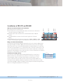
Installation of RS-422 and RS-485 ................................................................................................................................................. 31–32
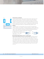
General recommendations for installation ............................................................................................................................. 31
Range and short-haul modems .............................................................................................................................................................. 31
20 mA current loop (TTY) ......................................................................................................................................................................... 31
10 mA balanced current loop (W1) ............................................................................................................................................. 32
Consequently the 10 mA balanced current loop
is less sensitive to external sources of interference .................................................................................................. 32
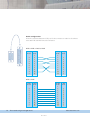
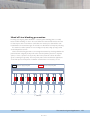
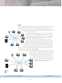
Network .............................................................................................................................................................................................................................. 33–34
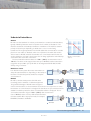
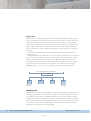
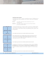
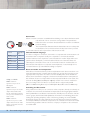
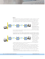
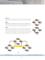
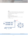
Topology .............................................................................................................................................................................................................................. 35–36
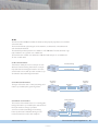
Serial point to point ............................................................................................................................................................................................... 35
Star network ..................................................................................................................................................................................................................... 35
Ring network .................................................................................................................................................................................................................... 35
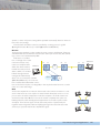
Bus network ....................................................................................................................................................................................................................... 36
Combined network ................................................................................................................................................................................................ 36
Mesh network ................................................................................................................................................................................................................. 36
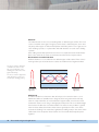
The Problem of Interference ................................................................................................................................................................. 37–42
Lightning, machinery and fluorescent lamps ............................................................................................................. 37–38
Overvoltage protection and lightning protection ............................................................................................ 38–39
Earth Loops ........................................................................................................................................................................................................................ 39
Reducing Interference .......................................................................................................................................................................................... 40
Balanced Signals ............................................................................................................................................................................................................ 40
Isolation .................................................................................................................................................................................................................................... 40
Ground networks ...................................................................................................................................................................................................... 41
Shielding ................................................................................................................................................................................................................................... 41
Short Connections without a modem ........................................................................................................................................ 41
Telecom modems and interference ................................................................................................................................................. 42
Fibre cable ............................................................................................................................................................................................................................ 42
www.westermo.com
Theoretical and general applications
5
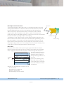
Types of copper cables .................................................................................................................................................................................. 43–44
Twisted pair wire ......................................................................................................................................................................................................... 43
Coaxial cable ..................................................................................................................................................................................................................... 44
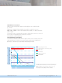
Distance and design ............................................................................................................................................................................................ 44–55
Transmission range with different types of cable media and data rates ...................................... 44
Calculation of resistance ................................................................................................................................................................................... 45
Two symbols for capacitance .................................................................................................................................................................... 45
Cable coding ..................................................................................................................................................................................................................... 46
Fibre Optic Communications .................................................................................................................................................................... 47
Fibre cable ............................................................................................................................................................................................................................ 47
Material ..................................................................................................................................................................................................................................... 48
Attenuation in multimode fibre ............................................................................................................................................................. 48
Multimode ............................................................................................................................................................................................................................ 48
Attenuation in singlemode fibre ............................................................................................................................................................ 49
Wave length ....................................................................................................................................................................................................................... 49
Light Attenuation in Glass Fibre at different wave lengths .............................................................................. 50
Termination ......................................................................................................................................................................................................................... 51
Loss Budget Calculation .................................................................................................................................................................................... 52
Example ................................................................................................................................................................................................................................... 52
OSI model ............................................................................................................................................................................................................................ 53
Structure of the OSI-model .............................................................................................................................................................. 53-54
A comparison ......................................................................................................................................................................................................
55
Local communication .............................................................................................................................................................................................. 56–65
Fieldbuses ........................................................................................................................................................................................................................... 56–57
Fieldbuses ............................................................................................................................................................................................................................... 57
PROFIBUS ............................................................................................................................................................................................................................ 58
History ....................................................................................................................................................................................................................................... 58
PROFIBUS communication .............................................................................................................................................................. 58–59
Network topology PROFIBUS ................................................................................................................................................................ 59
PROFIBUS DP ................................................................................................................................................................................................................ 60
Modbus ..................................................................................................................................................................................................................................... 61
Modbus Plus ...................................................................................................................................................................................................................... 62
Modbus/TCP ..................................................................................................................................................................................................................... 62
LON®WORKS ............................................................................................................................................................................................................ 63–65
Large LonTalk® network considerations .................................................................................................................................... 65
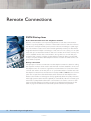
Remote Connections ......................................................................................................................................................................................... 66–109
PSTN Dial-up lines ........................................................................................................................................................................................................... 66
Data communication over the telephone network .................................................................................................. 66
Dial-up connection ................................................................................................................................................................................................... 66
Modulation ........................................................................................................................................................................................................................... 67
Is bit/s the same as baud? ............................................................................................................................................................................... 68
Some standards ............................................................................................................................................................................................................ 69
V.90 ................................................................................................................................................................................................................................................. 69
6
Theoretical and general applications
www.westermo.com
Connection ......................................................................................................................................................................................................................... 70
Telecom modem language ............................................................................................................................................................................ 70
Error correction and compression .................................................................................................................................................... 70
Searching and file transfer .............................................................................................................................................................................. 70
Tomorrow’s highways ........................................................................................................................................................................................... 71
Leased lines ......................................................................................................................................................................................................................... 71
V.23 on a leased line .............................................................................................................................................................................................. 72
Westermo V.23 modem ................................................................................................................................................................................... 72
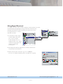
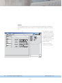
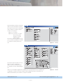
Using HyperTerminal (R) .................................................................................................................................................................................... 73–80
TDtool ........................................................................................................................................................................................................................... 76–77
AT-commands ...................................................................................................................................................................................................... 78–80
Higher speeds ..................................................................................................................................................................................................................... 81–83
xDSL ............................................................................................................................................................................................................................................. 81
HDSL ........................................................................................................................................................................................................................................... 81
ADSL ........................................................................................................................................................................................................................................... 81
VDSL ............................................................................................................................................................................................................................................ 81
SDSL ............................................................................................................................................................................................................................................. 82
SHDSL ....................................................................................................................................................................................................................................... 82
G.703 ........................................................................................................................................................................................................................................... 83
GSM .......................................................................................................................................................................................................................................... 84–96
The history of GSM .................................................................................................................................................................................... 84–85
Architecture ....................................................................................................................................................................................................................... 85
Components in the network .................................................................................................................................................................... 86
Cell structures ................................................................................................................................................................................................................. 87
Radio transmissions between MS and BSS ............................................................................................................... 87–88
Services on the GSM network ........................................................................................................................................................... 89–92
Telephony ............................................................................................................................................................................................................................ 89
Circuit Switched Data ....................................................................................................................................................................................... 89
SMS ................................................................................................................................................................................................................................................ 90
MMS .............................................................................................................................................................................................................................................. 90
Fax ................................................................................................................................................................................................................................................... 90
GPRS ................................................................................................................................................................................................................................ 91–92
Network security ................................................................................................................................................................................................... 92–95
GSM .............................................................................................................................................................................................................................................. 92
GPRS ............................................................................................................................................................................................................................................ 92
Differences between GSM and GPRS ......................................................................................................................................... 93
Applications with GSM and GPRS ........................................................................................................................................ 93–95
GPRS classes ..................................................................................................................................................................................................................... 96
UMTS (3G) ......................................................................................................................................................................................................................... 96
ISDN ..................................................................................................................................................................................................................................... 97–104
What is ISDN .................................................................................................................................................................................................................. 97
Signalling ................................................................................................................................................................................................................................... 97
Connections ....................................................................................................................................................................................................................... 97
www.westermo.com
Theoretical and general applications
7
ISDN components/interface ....................................................................................................................................................................... 98
Physical layer ...................................................................................................................................................................................................................... 99
Frame format of the S-interface ....................................................................................................................................................... 100
Layer 2 – Data link layer .............................................................................................................................................................................. 101
SAPI ........................................................................................................................................................................................................................................... 102
TEI ................................................................................................................................................................................................................................................ 102
Layer 3 – Network layer ............................................................................................................................................................................. 103
CAPI ......................................................................................................................................................................................................................................... 104
Radio ................................................................................................................................................................................................................................ 105–109
Radio communication ...................................................................................................................................................................................... 105
How it works ............................................................................................................................................................................................................... 105
Attenuation and noise ..................................................................................................................................................................................... 106
Antennas ..................................................................................................................................................................................................................... 107–109
Terminology .................................................................................................................................................................................................................... 107
The antenna and its components ................................................................................................................................................... 107
Types of antennas .................................................................................................................................................................................................. 108
Signal propagation ................................................................................................................................................................................................. 108
Radio network ............................................................................................................................................................................................................ 109
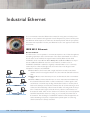
Industrial Ethernet .............................................................................................................................................................................................. 110–145
IEEE 802.3 Ethernet ................................................................................................................................................................................................. 110
Access methods ....................................................................................................................................................................................................... 110
Ethernet Address & Packets ................................................................................................................................................................... 111
Collision domain ...................................................................................................................................................................................... 112–113
IP Networks ........................................................................................................................................................................................................... 113–122
Internet Protocol .................................................................................................................................................................................................... 113
Addressing methods .......................................................................................................................................................................................... 113
Addressing in a network .............................................................................................................................................................................. 114
Private and public addresses .................................................................................................................................................................. 115
Ipv4 and Ipv6 ................................................................................................................................................................................................................ 116
Subnetwork division ........................................................................................................................................................................... 116–117
Ports .......................................................................................................................................................................................................................................... 118
ARP ............................................................................................................................................................................................................................................ 118
Point to Point (PPP) ........................................................................................................................................................................................... 119
Security (CHAP and PAP) ......................................................................................................................................................... 119–120
CHAP involves significantly improved security compared to PAP ................................................... 120
TCP/IP and UDP/IP ............................................................................................................................................................................................. 121
UDP ........................................................................................................................................................................................................................................... 121
TCP ............................................................................................................................................................................................................................................ 121
Establishing a TCP connection ............................................................................................................................................................. 122
Building a network ........................................................................................................................................................................................ 123–126
Devices in a network ........................................................................................................................................................................ 123–126
Repeaters ........................................................................................................................................................................................................................... 123
Bridge ...................................................................................................................................................................................................................................... 123
8 Theoretical and general applications
www.westermo.com
Router ..................................................................................................................................................................................................................... 124–125
Brouter .................................................................................................................................................................................................................................. 125
Hub ............................................................................................................................................................................................................................................ 125
Switch ...................................................................................................................................................................................................................................... 126
Gateway ............................................................................................................................................................................................................................... 126
Firewall ................................................................................................................................................................................................................................... 126
Hub or Switch .................................................................................................................................................................................................................... 127
Different types of switches ............................................................................................................................................................................... 128
FRNT and Spanning Tree .................................................................................................................................................................................... 128
Ringswitch ......................................................................................................................................................................................................................... 129
FRNT0 ................................................................................................................................................................................................................................... 129
FRNT1 ................................................................................................................................................................................................................................... 129
Time switches .............................................................................................................................................................................................................. 130
Switch functions ................................................................................................................................................................................................ 131–132
Prioritisation (QoS, Quality of Service) .................................................................................................................................. 131
Layer 2 priority .......................................................................................................................................................................................................... 131
Layer 3 priority .......................................................................................................................................................................................................... 132
Head of Line blocking prevention .......................................................................................................................................... 133–143
VLAN ...................................................................................................................................................................................................................................... 134
IGMP/IGMP snooping ...................................................................................................................................................................................... 135
Time synchronised networks ................................................................................................................................................................ 136
SNTP/NTP ....................................................................................................................................................................................................................... 137
Time stamping via applications ................................................................................................................................................... 137
Time stamping using Ethernet drivers .............................................................................................................................. 137
Time stamping on the physical layer ................................................................................................................................... 137
SNMP ...................................................................................................................................................................................................................................... 138
SNMP software ......................................................................................................................................................................................................... 139
SNMP, SNMPv2 and SNMPv3 ............................................................................................................................................................. 140
MIB .............................................................................................................................................................................................................................................. 141
OPC .......................................................................................................................................................................................................................... 141–143
Ethernet on the cable .................................................................................................................................................................................... 144–145
10 Mbit/s Ethernet ....................................................................................................................................................................................... 144–145
Fast Ethernet ......................................................................................................................................................................................................... 144–145
Gigabit Ethernet ............................................................................................................................................................................................... 144–145
Glossary .............................................................................................................................................................................................................................. 146–158
www.westermo.com
Theoretical and general applications
9
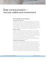
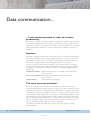
Data communication –
not just cables and connectors
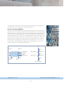
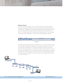
Industrial data communication
The industrial IT revolution
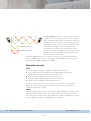
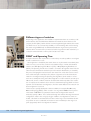
Competitive advantages can be achieved through creating new and efficient information channels in a company’s processes. Shorter delivery times, faster product development, customer-focused production and shorter changeover times, are just a few of
the key expressions pertaining to the industrial IT wave. Like fast access to information
and the possibility to control the processes. Industry develops IT tools that require
increased integration in all parts of a process, from purchasing to production and marketing. The quality of information paths and information flows is today one of the most
important conditions for increased efficiency and competitiveness for industry.
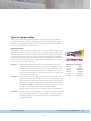
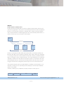
Different standards
New ideas, new systems and new solutions to create these IT-tools are emerging.
A negative consequence of this dynamic and all diversity is that for some time there
has been a lack of accepted standards, despite many attempts. Each developer has created his own solution. The problem of inadequate standards is discovered when computers, machines and equipment need to communicate. It is a question of standards
on many levels, not just for cables and connectors. It is about the manner in which data
is created, saved, compressed, addressed and sent, how the medium
(for example, a cable) carries, receives and decompresses the information and how
it is read by the receiver. When all this works we have effected data communication.
The prerequisite for industry’s IT development.
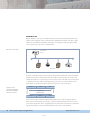
Industrial data communication
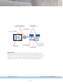
The largest steps within the standardisation of data communication have taken place
on the office side in the integrated network for personal computers, mainframes,
printers, servers, telecom modems, etc. Local data communication within industry has
not come into focus so much, this is due to the lack of standards and that diversity is
even greater as the communication should take place between, e.g. computers, lathes,
measurement equipment, scales, robots, transport systems and different alarm systems. Demands are greater on operating reliability and insensitivity to interference.
This is the reason behind this book, to bring some clarity to expressions, explain how
it works and to be a practical guide in solving problems within industrial data communication. If you would like to know more please do not hesitate to contact Westermo.
10
Theoretical and general applications
www.westermo.com
BACK
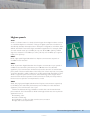
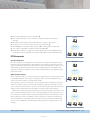
What is industrial data communication to us?
No downtime
All equipment must be designed so that communication interference and downtime
are eliminated. We achieve this by using high quality components, for example, capacitors with a long life and through validating designs in environments exposed to interference.
No maintenance
Our products are developed to withstand the harshest of environments without maintenance or service. In addition to the robust design, they never contain components
that need to be replaced such as batteries.
Harsh environments
Industrial equipment is normally installed together with or in the vicinity of other
equipment that generates interference, for example, welding equipment or heavy
machines. We have more than 30 years of experience in designing communication
equipment for industry and we use this know how in the development of industrial
equipment.
Extended temperature range
An extended temperature range is frequently required in industrial applications. We
guarantee functionality through the use of high quality components with an extended
temperature range, this applies to hardware such as connectors.
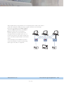
Mechanical performance
In industrial applications equipment is often mounted on machines that move or
vibrate. All our products are designed to withstand high mechanical stresses. As
important as mechanical reliability is the mounting method, consequently our range
comprises products for rack and DIN-mounting as well as table top or mini modem
models.
www.westermo.com
Theoretical and general applications
BACK
11
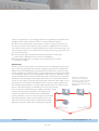
Galvanic isolation
One of the most common causes of communication errors is the problem with
potential differences between interconnected equipment. This is eliminated with galvanic isolation of the interface, this is one of the basic functions in our products.
Transient suppression
Industrial equipment is often exposed to interference generated by, e.g. high power
cables, reactive loads and different forms of transients. Products from Westermo are
designed to withstand these types of interference.
Power supply
It is important to have a reliable power source in industrial equipment, so a DC supply
is frequently used together with accumulators to eliminate downtime. When you
charge an accumulator a higher voltage than the battery voltage is used, therefore all
equipment must be designed for these conditions. Sometimes it is also important to
use a redundant power supply for twofold reliability, which many of our products have.
12
Theoretical and general applications
www.westermo.com
BACK
Determinism
When using equipment in real time applications it is important to have different
degrees of prioritisation. Our range of switches feature integrated functions and
queues that guarantee the transfer of prioritised data.
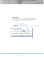
Approval
Our equipment is installed in different applications throughout the world. In order to
conform to local safety requirements, requirements governing electrical immunity/
emissions and mechanics, we design and produce based on international standards
and requirements.
www.westermo.com
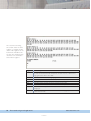
Westermo Teleindustri AB
Declaration of conformity
The manufacturer
Westermo Teleindustri AB
SE-640 40 Stora Sundby, Sweden
Herewith declares that the product(s)
Type of product
Model
Art no
Installation manual
DIN-rail
DIN-rail
DIN-rail
DIN-rail
DIN-rail
DIN-rail
DIN-rail
DIN-rail
DIN-rail
DIN-rail
SDW-550 LV
SDW-532-MM-SC2-SM-SC15 LV
SDW-541-MM-SC2 LV
SDW-541-MM-ST2 LV
SDW-541-SM-LC15 LV
SDW-541-SM-SC15 LV
SDW-532-2MM-SC2 LV
SDW-532-2MM-ST2 LV
SDW-532-2SM-LC15 LV
SDW-532-2SM-SC15 LV
3644-0010
3644-0019
3644-0020
3644-0021
3644-0022
3644-0024
3644-0030
3644-0031
3644-0032
3644-0034
6644-2211
6644-2211
6644-2211
6644-2211
6644-2211
6644-2211
6644-2211
6644-2211
6644-2211
6644-2211
is in conformity with the following EC directive(s).
No
89/336/EEG
Short name
Electromagnetic Compatibility (EMC)
References of standards applied for this EC declaration of conformity.
No
Title
Issue
EN 61000-6-2
EN 61000-6-3
Immunity for industrial environments
Emission standard for residential, commercial and
light industrial environments (3644 0010)
2 (2001)
1 (2001)
Theoretical and general applications
BACK
13
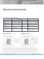
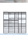
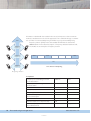
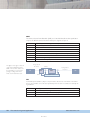
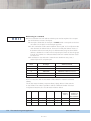
General technical data
Environmental and mechanical conditions
Factor
Temperature
Operating
Temperature
Storage & transport
Relative humidity
Operating
Relative humidity
Storage & transport
Airborne contaminants
severity level
Requirement
Severity
Standard
+5 to +55°C (+41 to 131°F)
IEC 721-3-3
–25 to +70°C* (–13 to 158°F *)
–25 to +70°C (–13 to 158°F)
IEC 721-3-1/2
5 to 95%, non-condensing
IEC 721-3-3
5 to 95% condensation allowed
outside packaging
G2 (1000 Å=0.1 µm) Moderate
IEC 721-3-1/2
ISA 71.04
Comments
Do not use until temperature and
humidity have stabilized
Product in packaging
Product installed in IP 21
enclosure, or better, with
limited air flow (no fan)
* Extended temperature range
Industrial environment
Outdoor environment
Accepted operating temperature +5 to +40°C
(+41 to 104 F)
Accepted operating temperature –25 to +55°C
(–13 to 131 F)
Temperature in cubicle
+5 to +55°C (+41 to 131 F)
Temperature in cubicle
–25 to +70°C (–13 to 158 F)
IP20
… Protection against
access to dangerous
voltage with a finger
… Protection against the
penetration of solid
foreign objects
≥12.5 mm (0.52 in)
… Protection against the
penetration of solid
foreign objects
≥12.5 mm (0.52 in)
Temperature in the product
+5 to +70°C (+41 to 158 F)
IP21
… Protection against
access to dangerous
voltage with a finger
Temperature in the product
–25 to +85°C (–13 to 121 F)
… Protection against
damage due to the
penetration of vertically falling dripping
water.
Specifications for temperature ranges and IP classification exist on different levels, we differ between industrial environments and outdoor installations. The components designed for respective variants must then withstand the ambient
temperature as well as the inherent heat generated in enclosures and cubicles. In general, each enclosure is considered
to generate a 15°C (59 F) increase in temperature, for example, components must be selected that withstand +85°C
(+121 F) in order for us to guarantee an ambient temperature (outside of the cubicle) of +55°C (+131 F).
14
Theoretical and general applications
www.westermo.com
BACK
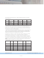
Electrical conditions
Factor
Emission
Immunity
Power supply (LV)
Rated voltage range
Operating voltage range
Power supply (HV)
Rated voltage range
Operating voltage range
Rated Power supply
frequency range
Reverse polarity
protection
Short circuit
protection
TNV-3
TNV-1
SELV
Requirement
Standard
EN 55022
class B
EN 61000-4-2
EN 61000-4-3
EN 61000-4-4
EN 61000-4-5
EN 61000-4-6
EN 61000-4-8
EN 61000-4-11
Information Technology
EN 55024
Equipment
Severity
EN 61000-6-3
Residential
EN 61000-6-2
Industrial
Comments
Reference
See 1.1 and 1.2
See 1.1 and 1.2
See 1.3
See 2.1
12 to 48 VDC
9.6 to 57.6 VDC
See 2.2
95–240 VAC
110–250 VDC
85.5–264 VAC
88–300 VDC
48 – 62 Hz
Yes
As a part of the
building installation
Maximum
70.7 V peak / 120 VDC
Maximum
42.4 V peak / 60 VDC
Maximum
42.4 V peak / 60 VDC
www.westermo.com
See 2.5
PSTN
or similar
See 2.4
RS-422/485,
Ethernet
or similar
See 2.3
RS-232
or similar
Theoretical and general applications
BACK
15
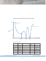
1.1 General emissions
EN 61000-6-3 EMC – Generic standards – Emission standard for residential,
commercial and light-industrial environments.
Emission
Immunity
Immunity = Tolerance against environmental effects.
Emission = Influence on environment (emanated energy).
The emission level is approx. 100 000 times lower than what our equipment handles
in terms of immunity.
Maximum levels for radio interference generated by equipment connected to the public network or DC-power source. The demands on emission levels are selected so
that interference generated by equipment during normal operation in homes, offices,
shops and similar environments do not exceed a level that obstructs other equipment
(for example, radio receivers) from working as intended.
1.2 ITE emissions
EN 55022 Information technology equipment (ITE) – Radio disturbance
characteristics – Limits and methods of measurement.
… Measurement methods and limit values for radio interference generated by ITE.
… Class B, ITE is intended for homes, offices, shops and similar environments. Does not
provide with guaranteed protection against the effects of radio and TV reception
when ITE is used at a distance less than 10 m (32.8 ft) from the receiver antenna.
… Class A, ITE is intended for all other environments (for example, industrial). Does
not provide with guaranteed protection against the effects of radio and TV reception when ITE is used at a distance less than 30 m (98.42 ft) from the receiver
antenna.
1.3 ITE immunity
EN 55024 Information technology equipment (ITE) – Immunity characteristics
– Limits and methods of measurement.
… Test requirement on ITE equipment for immunity to continuous and transient, conducted and radiated disturbances, including electrostatic discharges. Immunity
requirements provide a satisfactory level of inherent immunity so that equipment
works in the intended manner in its environment.
16
Theoretical and general applications
www.westermo.com
BACK
1.4 General immunity
EN 61000-6-2 Electromagnetic compatibility (EMC). Generic standards.
Immunity standard for industrial environments.
Radio*
Surge
• 50 Hz
• Magnetic field
power and pulse
ESD
Electrical Fast Transient
(Burst)
* Radiated field immunity.
Conducted radiofrequency fields.
Test requirement on equipment connected to networks in industrial environments for
immunity to continuous and transient, conducted and radiated disturbances (including
electrostatic discharges). Immunity requirements provide a satisfactory level of immunity for equipment in industrial environments.
1.5 EMC test method
EN 61000-4-2 Electromagnetic compatibility (EMC). Testing and measurement
techniques. Electrostatic discharge immunity test.
… Method for testing the immunity of electrical equipment against electrostatic
discharges, directly from operators or via adjacent objects. States a number of
test levels that refer to different environmental and installation conditions.
www.westermo.com
Theoretical and general applications
BACK
17
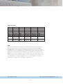
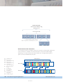
EMC severity levels in
different environments
Test
Residential
Residential, commercial and light-industrial environments.
Port
Emission
Radiated
Enclosure
Conducted
AC Power
Industrial
Immunity for industrial environments.
DC Power
Railway
Railway applications – Signalling and telecommunications
apparatus.
Substation
Communication networks and systems in electrical substations.
Westermo
A combination of residential, industrial, railway, added
with experiences from installed Westermo products.
Immunity
ESD
Radiated
field
immunity
Electrical
Fast
Transient
Surge
Conducted
radiofrequency
field
Encl. contact
Encl. air
Enclosure
Signal
AC Power
DC Power
Signal L-E
Signal L-L
AC Pow. L-E
AC Pow. L-L
DC Pow L-E
DC Pow L-L
Signal
Power
Power
Enclosure
magnetic field
Pulse
Enclosure
magnetic field
AC power* Power
Criteria, a classification of performance
Criteria A: Normal performance within specified limits
(as defined in test specification).
Criteria B: Temporary loss of function or degradation of performance which ceases after the disturbance ceases, and from which the equipment under test
recovers its normal performance, without operator
intervention.
Criteria C: Temporary loss of function or degradation of performance, the correction of which requires operator intervention.
DC power
Oscillatory
waves
50 Hz disturbances**
Power
Signal L-E
Signal L-L
Power L-E
Power L-L
Signal L-E
Signal L-L
Westermo
Level
Criteria
30/37
dB (µV/m)
66-56/56/60
Qp dB (µV)
66-56/56/60
Qp dB (µV)
Class
B
Class
B
Class
B
± 6 kV
± 8 kV
20 V/m
1 kHz
80% AM
20 V/m
200 Hz
pulse
± 2.0 kV
± 2.0 kV
± 2.0 kV
± 2.0 kV
± 2.0 kV
± 2.0 kV
± 2.0 kV
± 2.0 kV
± 2.0 kV
10 V
1 kHz
80%AM
10 V
1 kHz
80%AM
100 A/m
50 Hz
300 A/m
6.4/16 µs
30% 10/500 ms
60% 100/1000 ms
Interrupt 10/5 ms
30% 10 ms
60% 10 ms
Interrupt 10/100 ms
20% above/below
rated voltage
–
–
–
–
10/100 V
250 V
B
B
A
A
A
A
A
B
B
B
B
B
B
A
A
A
–
B
B
B
B
B
–
–
–
–
A
A
* Voltage dips, short interruptions and voltage variations.
** Conducted common and differential mode.
18
Theoretical and general applications
www.westermo.com
BACK
Test
Port
Level
Emission
Radiated
Enclosure
Conducted
AC Power
DC Power
Immunity
ESD
Radiated
field
immunity
Electrical
Fast
Transient
Surge
Conducted
radiofrequency
field
Encl. contact
Encl. air
Enclosure
Signal
AC Power
DC Power
Signal L-E
Signal L-L
AC Pow. L-E
AC Pow. L-L
DC Pow L-E
DC Pow L-L
Signal
Power
Power
Enclosure
magnetic field
Pulse
Enclosure
magnetic field
AC power* Power
DC power
Oscillatory
waves
50 Hz disturbances**
Power
Residential
Criteria
Level
Industrial
Criteria Level
Railway
Criteria
Level
Substation
Criteria
30/37
dB(µV/m)
66-56/56/60
Qp dB(µV)
–
Class
B
Class
B
–
40/47
dB(µV/m)
79/73
Qp dB(µV)
–
Class
A
Class
A
–
40/47
dB(µV/m)
79/73
Qp dB(µV)
79/73
Qp dB(µV)
Class
A
Class
A
Class
A
30/37
dB(µV/m)
66-56/56/60
Qp dB(µV)
–
Class
A&B
Class
A&B
–
± 4 kV
± 8 kV
3 V/m
1 kHz
80% AM
B
B
A
± 4 kV
± 8 kV
10 V/m
1 kHz
80% AM
B
B
A
± 6 kV
± 8 kV
20 V/m
1 kHz
80% AM
20 V/m
200 Hz
pulse
± 2.0 kV
± 2.0 kV
± 2.0 kV
± 2.0 kV
± 2.0 kV
± 2.0 kV
± 2.0 kV
± 2.0 kV
± 2.0 kV
10 V
1 kHz
80%AM
10 V
1 kHz
80%AM
100 A/m
50 Hz
300 A/m
6.4/16 µs
–
B
B
A
± 6 kV
± 8 kV
10 V/m
1 kHz
80% AM
A***
A***
A
± 2.0 kV
± 4.0 kV
± 4.0 kV
± 4.0 kV
± 4.0 kV
± 4.0 kV
± 4.0 kV
± 4.0 kV
± 4.0 kV
10 V
1 kHz
80%AM
10 V
1 kHz
80%AM
100 A/m
50 Hz
–
A***
A***
A***
A***
A***
A***
A***
A***
A***
A
Interrupt
10 ms
Interrupt
arbitrary
2.5 kV
1.0 kV
2.5 kV
1.0 kV
30 V Cont.
300 V 1 s
250 V
A
± 0.5 kV
± 1.0 kV
± 0.5 kV
± 0.5 kV
–
± 2.0 kV
± 1.0 kV
± 0.5 kV
± 0.5 kV
3V
1 kHz
80%AM
3V
1 kHz
80%AM
3 A/m
50 Hz
–
30% 0.5 s
60% 100 ms
Interrupt 5 s
–
B
B
B
B
B
B
B
B
–
B
B
B
B
A
–
± 1.0 kV
± 2.0 kV
± 2.0 kV
± 1.0 kV
–
± 2.0 kV
± 1.0 kV
± 0.5 kV
± 0.5 kV
10 V
1 kHz
80%AM
10 V
1 kHz
80%AM
30 A/m
50 Hz
–
B
C
C
–
30% 10 ms
60% 0.1/1 s
Interrupt 5 s
–
B
C
C
–
B
B
B
B
A
A
A
A
A
–
–
A
A
A
A
B
B
B
B
B
B
A
A
A
B
A
A
–
–
–
Signal L-E
Signal L-L
Power L-E
Power L-L
Signal L-E
–
–
–
–
–
–
–
–
–
–
–
–
–
–
–
–
–
–
–
–
–
–
–
–
–
–
–
–
–
–
Signal L-L
–
–
–
–
–
–
C
A***
A***
A***
A***
A
A
*
Voltage dips, short interruptions and voltage variations.
** Conducted common and differential mode.
*** During the disturbance in communication error accepted if no delays or data loss for critical functions. Changes in states of
electrical, mechanical or communication signal outputs are not allowed, this includes alarms and status outputs.
www.westermo.com
Theoretical and general applications
BACK
19
EN 61000-4-3 Electromagnetic compatibility (EMC). Testing and measurement
techniques. Radiated, radio-frequency, electromagnetic field immunity test.
… Method for testing the immunity of electrical equipment against radiated, radio frequency, electromagnetic fields. States a number of test levels and test methods.
EN 61000-4-4 Electromagnetic compatibility (EMC). Testing and measurement
techniques. Electrical fast transient/burst immunity test.
… Method for testing the immunity of electrical equipment against fast transients and
bursts. States a number of test levels and test methods.
EN 61000-4-5 Electromagnetic compatibility (EMC). Testing and measurement
techniques. Surge immunity test.
… Method for testing the immunity of equipment against surges caused by lightning
or switching of large loads. States a number of test levels that refer to different
environmental and installation conditions.
EN 61000-4-6 Electromagnetic compatibility (EMC). Testing and measurement
techniques. Immunity to conducted disturbances, induced by radio-frequency fields.
… Method for testing the immunity of electrical equipment against conducted
disturbances caused by radio frequency fields within the frequency range 9 kHz
to 80 MHz. States a number of test levels and test methods.
EN 61000-4-8 Electromagnetic compatibility (EMC). Testing and measurement
techniques. Power frequency magnetic field immunity test.
… Method for testing the immunity of electrical equipment against power frequency
magnetic fields. States a number of test levels that refer to different environmental
and installation conditions.
EN 61000-4-11 Electromagnetic compatibility (EMC). Testing and measurement
techniques. Testing and measurement techniques. Voltage dips, short interruptions
and voltage variations immunity tests.
… Method for testing the immunity of electrical equipment against voltage dips, short
interruptions and voltage variations. States a number of test levels and test methods.
20
Theoretical and general applications
www.westermo.com
BACK
Safety conditions
Factor
Electrical safety
Service life
Supply connection
Accessibility
Maintenance
Isolation
Circuit
Supply
Supply HV
SELV
TNV-1
TNV-1
TNV-3
Requirement
Severity
Standard
Information technology
EN 60 950
equipment
10 years
Permanently connected
Restricted access location
Comments
Reference
See 1.6
Access, by
service personnel
and by tool
No
To Circuit(s)
All other
All other
TNV-1, TNV-3
TNV-3
TNV-1
TNV-3
Electric strength
≥1 kVAC
3 kVAC
1 kVAC
1 kVAC
1 kVAC
1 kVAC
See 2.3
See 2.4
See 2.5
Installation conditions
Installation
Power supply
Power supply (HV)
TNV-3
(<70.7 Vp 120 VDC)
TNV-1
(<42.4 Vp 60 VDC)
SELV
(<42.4 Vp 60 VDC)
Inst. Cat
II
II
Cable type
Port
Power
Power
Comments
I
Unshielded
Signal balanced
PSTN or similar
I
Twisted pair,
unshielded
Signal balanced
RS-422/485,
Ethernet or similar
I
Unshielded
Signal
RS-232 or similar
www.westermo.com
Theoretical and general applications
BACK
21
1.6 Electrical safety
EN 60950 Information technology equipment. Safety. General requirements.
… ITE safety standard that defines the requirements to reduce the risk of fire, electric
shock or injury to the user and those coming into contact with the equipment as
well as service personnel. Applicable to mains connected and battery fed ITE as
well as ITE intended for direct connection to the telephone network, irrespective of
feeding source.
Enclosure
Factor
Dimension (W x H x D)
mm (in)
Weight kg (pounds)
Mounting
Degree of protection
Cooling
Enclosure material
Fire rating
Severity
55 x 100 x 128
(2.17 x3.94 x 5.04 in)
35 x 121 x 119
(1.43 x 4.76 x 4.69 in)
< 0.6 (<1.3)
35 mm DIN-rail
Standard
Comments
Reference
2 card DIN-rail
1 card DIN-rail
IP 20
Convection, spacing:
10 mm (0.4 in)
(left/right)
25 mm (1.0 in) (above/below)
PC / ABS
Flammability class V-0
EN 60715
Snap on mounting
(EN 50022)
IEC 529
Spacing (left/right)
recommended
for full operating
temperature range
UL 94
See 1.7
See 1.8
1.7 Degree of protection
IEC 529 Degrees of protection provided by enclosures (IP Code)
… Classification of the degree of protection provided by electrical enclosures.
Protection of:
… Persons, against dangerous voltage inside the equipment
… Inside the equipment, against the penetration of solid foreign objects
… Inside the equipment, against damage due to the penetration of water.
For example IP 21:
… Protection against access to dangerous voltage with a finger
… Protection against the penetration of solid foreign objects ≥12.5 mm (0.51 in)
… Protection against damage due to the penetration of vertically
falling drip water.
22
Theoretical and general applications
www.westermo.com
BACK
1.8 Flammability
UL 94 The Standard for Flammability of Plastic Materials for Parts in Devices and
Appliances
… Methods to measure and describe the characteristics of specimen materials relating
to flammability, when exposed to heat and flames under controlled forms in a laboratory environment.
2 Definitions
2.1 Rated voltage range
… Voltage range specified by the manufacturer.
2.2 Operating voltage range
… Voltage range within which the device, under the specified conditions, can perform
its intended functions. Rated voltage range and upper and lower tolerances.
2.3 SELV
… A secondary circuit which is so designed and protected that, under normal and single fault conditions, its voltages do not exceed a safe value.
2.4 TNV-1
… A secondary circuit whose normal operating voltages do not exceed the limits for a
SELV circuit under normal operating conditions and where overvoltages from
telecommunication networks are possible.
2.5 TNV-3
… A secondary circuit whose normal operating voltages exceed the limits for a SELV
circuit under normal operating conditions and where overvoltages from telecommunication networks are possible.
www.westermo.com
Theoretical and general applications
BACK
23
Data communication...
...is extremely important in order to increase
productivity
Increases in automation also place demands on reliable data communications between
units and the systems that control and those producing and measuring. Data communication is the nervous system that forms the basis of increased efficiency and competitiveness. Irrespective of whether it concerns manufacturing, installation, transport or
healthcare.
Interface
Agreement regarding the signal type, how they should be converted and transmitted is
not enough. Agreement is also required regarding the type of connector and the voltage levels they need to support, in other words, the physical and electrical interface.
There is also a logical interface, which defines the significance of the signal.
A protocol controls how the signals are built up, how communications are initiated,
how they are terminated, the order of transmitting and sending, how to acknowledge
a message, etc. There are many different protocols, for example, PROFIBUS, Comli,
Modbus, etc.
The physical interface defines how equipment is connected as well as the design
of the connector.
The electrical interface defines the electrical levels and what these denote
(ones or zeros).
Logical interface
defines what the signals signify.
The most common interfaces
The most common interface for data communication via computer equipment’s
serial port is RS-232/V.24, which usually uses a 9-/25-pos. D-sub connector. According
to the recommendations for RS-232/V.24, the cable between connected units should
not exceed 15 metres (49 ft). Different modems can be used to achieve greater transmission distances depending on the communications media available (e.g. fibre, copper,
telecommunication circuit). V.24 (European CCITT standard) or RS-232-C (American
ITU-T standard) are two standards that are in principle identical, see the table on page
25. V.24 describes the physical standard while V.28 is the electrical standard. That is
why you sometimes see the interface described as V.24/V.28.
The interface describes and defines the connector’s pins, the signals and voltage
levels supported.
24
Theoretical and general applications
www.westermo.com
BACK
Signals in V.24/RS-232-C
Pin
9/25
V.24
Code
1
2
3
4
5
6
7
8
9
10
11
12
13
14
15
16
17
18
19
4 20
21
9 22
23
24
25
101
103
104
105
106
107
102
109
–
–
126
122
121
118
114
119
115
–
120
108/2
110
125
111
113
133
3
2
7
8
6
5
1
RS-232
Code
AA
BA
BB
CA
CB
CC
AB
CF
–
–
SCF
SCB
SBA
SBA
DB
SBB
DD
–
SCA
CD
CG
CE
CH/CI
DA
–
Signal
Signal name
GND
TD
RD
RTS
CTS
DSR
SG
DCD
Protective Ground
Transmitted data
Received data
Request To Send
Clear To Send
Data Set Ready
Signal Ground
Data Carrier Detector
can be + 12 V
can be – 12 V
Select Transmit Frequency
Secondary DCD
Secondary CTS
Secondary TD
Transmit Clock
Secondary RD
Receive Clock
–
Secondary RTS
Data Terminal Ready
Signal Quality Detect
Ring Indicator
Data Signal Rate Selector
External Clock
Ready For Receiving
STF
TC
RC
DTR
SQD
RI
EC
RFR
Direct.
DCE
–
I
O
I
O
O
–
O
–
–
I
O
O
I
O
O
O
–
I
I
O
O
O
I
I
14
15
16
17
18
19
20
21
22
23
24
25
1
2
3
4
5
6
7
8
9
10
11
12
13
6
7
8
9
1
2
3
4
5
Bold type indicates the most common signals in local communications using shorthaul modems. Direction I/O indicates the direction to/from the modem (DCE)
where I is an input and O an output. Accordingly, the TD (Transmit Data) signal is
the output in a DTE yet the input in a DCE. The definition of DCE and DTE is one of
the most common sources of error, when these are linked to RS-232 equipment, see
page 26.
www.westermo.com
Theoretical and general applications
BACK
25
Cable configuration
How the connection between 9-/25-pos. D-sub connectors is made for all combinations with DTE and DCE units is shown below.
DTE to DTE or DCE to DCE
9 Way
D-sub
3
25 Way
1
D-sub
2
1
3
2
4
3
5
4
6
5
7
6
8
7
20
8
22
20
9 Way
D-sub
3
2
3
7
2
8
7
6
8
5
6
1
5
4
1
9
4
25 Way
1
D-sub
2
1
3
2
4
3
5
4
6
5
7
6
8
7
20
8
22
20
9
22
22
9
25 Way
D-sub
25 Way
D-sub
9 Way
D-sub
1
1
2
1
3
2
4
3
5
4
6
5
7
6
8
7
20
8
22
20
2
1
3
2
4
3
5
4
6
5
7
6
8
7
20
8
22
20
3
2
3
7
2
8
7
6
8
5
6
1
5
4
1
9
4
9
22
22
9
2
3
7
2
8
7
6
8
5
6
1
5
4
1
9
4
DTE to DCE
9 Way
D-sub
3
26
Theoretical and general applications
2
3
7
2
8
7
6
8
5
6
1
5
4
1
9
4
www.westermo.com
BACK
Key to the most important signals
Explanation of the most important signals
GND Protective Ground
Pin no. 1 is reserved for protective ground
between the devices.
SG
Signal Ground
Signal ground is a signal reference and must
always be connected to pin 7 (25-pin)
pin 5 (9-pin) in V.24.
TD
Transmitted Data
This signal transmits data from a DTE to a DCE.
RD
Received Data
This signal is the data that a modem or a DCE
transmits to a DTE.
RTS
Request to Send
This signal is a request to send data from a DTE.
The device waits for the CTS answer signal.
CTS
Clear to Send
The answer signal from DCE which tells the DTE
that it can transmit data.
DSR
Data Set Ready
The signal from a DCE which indicates that the
device is switched on, connected and ready.
DTR
Data Terminal Ready
The same as DSR, but from a DTE.
DCD Data Carrier Detect
The output signal from a DCE which indicates that
there is a carrier between the DCEs and that the
connection is ready for communication.
EC
External Clock
This signal is used in synchronous transmission
when it is necessary to clock data. The signal is the
input into the DCE.
TC
Transmit Clock
Transmits the DCE clock in synchronous systems.
RC
Receive Clock
Clock received in the DTE for decoding data.
RI
Ring Indicator
Output signal from a modem indicating that it has
received a ring signal.
www.westermo.com
Theoretical and general applications
BACK
27
ASCII
ASCII is an abbreviation for American Standard Code for Information Interchange.
The ASCII code is available in different versions for different languages and in an
Extended ASCII where the 8th data bit is utilised.
BINARY
b6
0
b5
0
0
b4
b 3 b2 b 1 b0
28
0
0
0
0
1
1
1
1
0
1
0
1
HEX
0
1
2
3
1
1
0
1
0
1
4
0
5
@
1
1
6
7
`
0
0
0
0
0
NUL
DLE
SP
0
0
0
0
1
1
SOH
DC1
!
1
A
Q
a
q
0
0
1
0
2
STX
DC2
"
2
B
R
b
r
0
0
1
1
3
ETX
DC3
#
3
C
S
c
s
0
1
0
0
4
EOT
DC4
4
D
T
d
t
0
1
0
1
5
ENQ
NAK
%
5
E
U
e
u
0
1
1
0
6
ACK
SYN
&
6
F
V
f
v
0
1
1
1
7
BEL
ETB
'
7
G
W
g
w
1
0
0
0
8
BS
CAN
(
8
H
X
h
x
1
0
0
1
9
HT
EM
)
9
I
Y
i
y
1
0
1
0
A
LF
SUB
*
:
J
Z
j
z
1
0
1
1
B
VT
ESC
+
;
K
[
$
€
P
É
Ä
1
1
0
0
C
FF
FS
,
<
L
\
1
1
0
1
D
CR
GS
-
=
M
]
1
1
1
0
E
SO
RS
.
>
N
^
1
1
1
1
F
SI
US
/
?
O
Theoretical and general applications
Ö
Å
Ü
_
p
é
k
{
l
|
m
}
n
~
o
DEL
ä
ö
å
ü
www.westermo.com
BACK
Industrial interfaces
Meter
10 000
RS-422
RS-422 is an ideal standard for industry as the interface is created to build data buses,
typically multidrop, between central computers and a number of substations. The
interface is balanced and relatively insensitive to interference. The interface switches
polarity on the wire pair depending on whether it is a one or a zero being
transferred. The original specification for RS-422 states that communications can take
place from one master to 10 slaves, which can only listen to the traffic. We use the
drive circuits for RS-485, where the transmitter can communicate with 32 units and
can be operated to “tri-state”, which means we can design applications with multidrop
over both 4-wire and 2-wire connections.
The recommended maximum distance is 1200 m (4000 ft) at a transmission rate of
100 kbit/s. The drive circuits support data rates up to 10 Mbit/s, but the transmission
range then drops to 20 m (66 ft). RS-422 can be integrated with RS-485, RS-232/
V.24 by using a converter.
RS-422 on 4-wire
In an RS-422 4-wire system the master transmitter can
always be active/switched on, depending on the activity of
the slaves. The standard permits simultaneous duplex
communications.
RS-232
DEVICE
TD
RD
RTS
DTR
SG
www.westermo.com
100
10
10 kb/s
100 kb/s
1 mb/s
10 mb/s
RS-485 communication
distance
TX A
TX B
RX A
RX B
TD
RD
RTS
DTR
SG
TD
TD
RS-485
RD
RD
RS-422
RTS
RTS
RS-485 is a further development of RS-422 and is
DEVICE
DTR
DTR
SG
SG
increasingly used as standard on different equipment.
The greatest advantage of RS-485 is that it supports
2-wire communications, i.e. the transmitter and receiver in the equipment can switch
the direction of communication. It is designed for data buses of up to 32 devices and is
suitable for multidrop networks where a master/slave relation is employed. The recommended maximum range is 1200 m (4000 ft) with a transmission
rate of 100 kbit/s. there are many different standard interTD
TD
RD
RD
faces that use RS-485 as its physical media, for example,
RS-232
RTS
RTS
DEVICE
DTR
DTR
PROFIBUS, Interbus-S and Bitbus.
SG
SG
Termination
1 200
1 000
RX A
RX B
TX A
TX B
RS-422
DEVICE
TX A
TX B
RX A
RX B
RS-422
RS-422
RS-422
DEVICE
DEVICE
DEVICE
A
B
RS-485
RS-485
RS-485
DEVICE
DEVICE
DEVICE
Theoretical and general applications
BACK
29
+5 V
R+
R-
0V
Termination and Fail-Safe
The line should be terminated using a resistor that has the same value as the characteristic impedance for the line. This resistance should be approximately 120 ohm.
Termination should be applied as shown in the diagrams on page 29. Termination
should be made at each end of the bus. Termination prevents reflections in the cable.
“Fail-safe” is a resistance from each wire to the + supply on the one hand, and to the
0V on the other. This means the line is drawn to a predetermined passive level, otherwise the line will fluctuate with the risk of disturbances being detected as data.
Polarity
The interconnection of the transmitter and receiver must be done with the right
polarity, in relation to each other. By connecting equipment from different suppliers we
know from experience that standards can be interpreted differently. A polarity error in
relation to other equipment means that this equipment will interpret the data incorrectly. According to the standard, the transmitter is designated by
A and B, these are connected to A´ and
A (T+)
A' (R+)
B´. We have chosen to clarify these designation with T+, T–, R+ and RB (T–)
B' (R–)
(transmit/receive + and –).
RS-232/V.24 to RS-422/485 converter – RTS support
Systems with RS-422/485 converters in a multidrop network, only permit one transmitter at a time to be active on the bus. Other devices’ transmitters must be in “tristate” mode, i.e. passive. In order to achieve this, it must be possible to control connected equipment by means of a hardware signal. RTS or DTR signals are usually used
for this. When a device wishes to transmit on the bus it must first set its RTS or DTR
signal high, so that the converter switches its transmitter, it can then send data. When
no hardware signal is available, it is possible to use a special converter, which switches
on its transmitter as soon as data is sent via RS-232 and switches off as soon as the
data stops.
30
Theoretical and general applications
www.westermo.com
BACK
Stop bit
Data bits
Start bit
General recommendations for installation
… Twisted pair wire should be used.
… Star networks are not permitted and distance from the bus to the device
must be a maximum of 30 cm (1ft).
… Receivers at the end of the bus are to be terminated with a 120 ohm
resistor.
… The RS-232/V.24 connection should not be longer than 15 metres
(50 ft).
… RS-422/485-supports transmission ranges up to 1200 m (4000 ft) at 100
kbit/s. However, great ranges can be achieved at lower transmission rates.
Parity bit
Installation of RS-422 and RS-485
+5 V
Tristate
B
A
0V
Range and short-haul modems
As mentioned earlier, the RS-232/V.24 standard does not recommend cabling longer
than approximately 15 metres (50 ft). Short-haul modems are used to allow longer
links to be made. These convert the RS-232/V.24 into defined electrical or optical signals, which are transmitted on e.g. a permanent 4-wire connection or fibre up to a distance of several kilometres. The short-haul modem at the receiver then converts the
signal back to RS-232/V.24. The modem must use a common standard and an identical
interface for communications over the cable.
20 mA current loop (TTY)
T+
TCurrent Loop is the oldest technique. RS-232/V.24 signals are coded onto a
R+
20 mA current loop as the absence or presence of a current on a wire pair.
RThe transmitter is either connected active and the receiver passive, or vice
versa, to feed each wire pair with current. Current Loop provides reliable communications, but is relatively sensitive to interference as the current loop is not balanced (see page 40). In addition, problems can be experienced with the equipment as
there is no recognized standard for Current Loop.
www.westermo.com
20 mA
R+
R20 mA
T+
T-
Theoretical and general applications
BACK
31
10 mA balanced current loop (W1)
Westermo has developed its own transmission technology for short-haul modems
that ensures communications over greater distances and in environments with a high
level of interference. The technology is based on converting the signals to a ±10 mA
balanced current loop, where the current direction is shifted on the wire pair, depending on whether it is a high or low signal from RS-232/V.24. The line on the transmitter
is powered by ±10 mA and an optocoupler is fitted on the receiver to detect the signals. The optocouplers provide complete galvanic isolation between modems. Current
is always flowing in one direction even when there is no equipment connected on the
RS-232/V.24 side. The exception is when the transmitter is controlled/activated using a
handshaking signal. It is a tried and trusted technique that over the years has proven to
be very reliable and insensitive to interference and supports data transmission at
ranges up to 18 km (11 mi).
Consequently the 10 mA balanced current loop is less sensitive to external sources of interference.
Compared with an unbalanced current loop, a balanced current loop is significantly
less sensitive to external disturbance due to the potential differences remaining even
when interference is experienced on the line. See the figure below.
3
1. Data is sent to the
transmitter.
2. Data on wire A is inverted
compared to the data on
wire B.
3. The line is exposed
to interference.
4. Transmission data superposed on the interference.
5. Data arriving on the receiving
side is unchanged from the
data sent by the transmitter
(1).
32
2
A
+
TD
RD
B
+
-
4
1
Wire A
Wire B
Theoretical and general applications
5
www.westermo.com
BACK
Network
The local network’s breakthrough came during the eighties, initially via centrally located
mainframe or minicomputers with terminals connected in a star. The establishment of
these networks also resulted in a need for reliable and secure data communication.
Transmission requires: A transmitter, a receiver, a medium, information and a protocol. The transmitter, receiver and media require a specification for the physical devices
(how to connect to a network, etc). While the protocol manages the regulations for
how the transfer is implemented, this is described in detail in a later section.
A local network can include data communication for offices as well as for industry, hospitals, mine operations or traffic surveillance. A powerful network and reliable communication is one of the basic elements in order for companies or organisations to develop through:
… Information being shared, common databases can be used, e-mail and file sharing
increases working efficiency yet further.
… Shared resources, several users share valuable resources in the network such as
colour printers or common software on a server.
… Security, through access privileges to the network for individual users or groups
of users access to individual applications can be controlled. And in doing so
increasing the efficiency of administration on a central level.
Nodes are regularly mentioned when speaking about networks, a node is for example
a computer, a printer or communication equipment. As there are many different types
of nodes with a broad number of functions, it is extremely important
that there are regulations for how these should communicate.
Node
Node
Node
In the same way as we humans need to speak the same language to
understand each other, equipment in the network must speak the same
language. This is regulated via a protocol, which determines how communication is to take place, what may be said, by whom, when and
Node
Node
how. These protocols must be harmonised so that all suppliers observe
the same regulations. Standards can be developed by individual companies (de-facto
standards) or by official decision-making bodies such as ISO, ANSI or IEEE.
www.westermo.com
Theoretical and general applications
BACK
33
The quality of a network depends, among others on:
… Speed, which in turn depends on the number of simultaneous users, media,
hardware and software.
… How the transmission takes place, whether it reaches the right receiver and
only the right receiver.
… The quality of the data, minimization of communication disturbances.
… Speed of the network.
… Reliability, how well the network is protected against transients, earth currents
and other phenomenon that can disturb communications.
… Security – How secure is the network against attack and viruses.
The need to be able to link different local networks has constantly increased, so that
data can be transferred between companies or within a company, nationally or internationally. How do the different computer systems and databases in a company communicate when they are spread across the world? The options are numerous:
… LAN (Local Area Netwok) fast network for local communication, for example,
Ethernet.
… MAN (Metropolitan Area Network) fast network that covers a greater geographical area.
… WAN (Wide Area Network) a network with a very large geographical
distribution, it may be a country or even the whole world.
… VAN (Value Added Network) is a network that offers more developed
services than just data communication.
… GAN (Global Area Network) is a network consisting of several local networks
that can be interconnected via MAN and fast WAN.
… AAN (All Area Network) a network that can be used in both local and more
geographically widespread networks.
34
Theoretical and general applications
www.westermo.com
BACK
Topology
The expression topology refers to how a network is structured; the physical or logical
placement of the nodes. There are five basic topologies: point to point, ring, star, bus
and combined network. The choice of topology is important, as it is a long term infrastructure that shall manage and transport important data without downtime.
In addition, it must be possible to adapt and expand the network as and when conditions change.
Serial point to point
Point to point data communications, i.e. between two communicating devices is
Node
one of the most common applications. Both in basic applications, such as computer to printer, and more complex applications, where you choose to allow each user
to communicate on their own line for reasons of security. The standard RS-232/V.24
interface is not recommended for transmission distances greater than 15 metres
(50 ft). For this reason a modem is used to extend the line and suppress disturbance
for communication up to 18 km (11 mi).
Star network
A network with many connected point to point users is known as a star network. Node
Each device communicates with the central unit in the centre on its own line. The
star network offers the advantage of high reliability. When a line goes down the
others are not affected. One disadvantage is that more cable is required, resulting
in a higher cost, and that all communications must go through the central unit.
Node
Ring network
A ring network connects all units in series with each other in a closed ring. This
means that all communications must pass “through” all devices on the ring in order to
be forwarded to the receiver. An “empty slot” is sent round the network to avoid collisions. The transmitting node checks whether it is empty, attaches its address and
adds its data information. The next node in the ring checks whether the contents
of the slot are intended for it, if not is passed on. When the receiver receives its
slot, he empties its contents and inserts a receipt and sends this out on the network again. The transmitting device checks that the message has been received
and acknowledged, it then sends the empty slot forward for new traffic. Token Ring
is an example of a ring network from a signal standpoint, which is physically connected as a distributed star network. Ring networks offer high performance, but
can be more complicated to build and adapt compared to a bus network.
www.westermo.com
Node
Node
Node
Node
Node
Node
Node
Node
Theoretical and general applications
BACK
35
Bus network
In principle a bus network consists of a main line where all units are connected as
nodes. All data traffic is sent out via the bus to the receiver. A bus network must have
regulations for how a transmitting device checks whether the line is free and how it
should act in the event of a transmission colliding with other data traffic, for example
through delayed retransmission. The bus network is easy to install,
Node
expand and extend. Ethernet and AppleTalk are common examples of a
bus network. Among the disadvantages is slow traffic when many
devices need to communicate on the network. However, the bus network can be divided up into several short buses, which segment the
Node
network.
Node
Node
Node
Node
Node
Node
Node
Node
Node
Node
Combined network
Using different communication products means that you can create your own customised network solution that combines the advantages of the different
topologies, including performance and reliability. For example, a bus netNode
work with a distributed star, which is a way to link together several star
networks. It is important to remember that each network needs to have
a fully working regulation system, traffic regulations, for data communications.
Node
Mesh network
Networks that are interconnected without a structure are known as a mesh network.
In a poorly documented network without structure the risk of communication errors
created by mistake is considerable. Suppose you connect in another node and in doing
so create a loop, a broadcast will then circulate in the network, further
broadcasts add traffic and in the end you have a broadcast storm in your
Node
network.
Node
Node
Node
36
Node
Theoretical and general applications
www.westermo.com
BACK
The Problem of Interference
Unfortunately not everything is resolved just because we have succeeded in finding the
right transmission methods and the right interface. The largest irritant to data communications still remains-Interference. Outside disturbances that result in data loss, transmission errors and in the worst possible scenario knock out equipment. Computer
development has resulted in smaller circuits and components being driven by less
power. This is ideal from an energy standpoint, but regrettably they have also become
more sensitive and more vulnerable to overvoltages. Investigations have shown that up
to 70% of all data disturbances are due to deficiencies in the installations or disturbances from the local environment, from neighbouring equipment, machines and
cabling. Only 20% are due to either hardware or software faults. Accordingly, most culprits can be found within our own walls or in the vicinity. The others come from outside. Like a bolt from the blue. The largest group is transients. Short yet high voltage
pulses on the network. Computer equipment exposed to transients, 1,000 V and
upwards to 10 kV lasting a few milliseconds, lives dangerously.
Lightning, machinery and fluorescent lamps
We know that a direct stroke of lightning discharges very high voltage and that these
propagate and damage electrical and telecommunication lines, and in worse cases
result in fire. Though you may escape a direct hit, you can be affected by pulses that
propagate over large distances in the cable network or by earth potential differences
between two points. That is why a light can flicker even when a storm seems a long
way off.
Lightning causes differences
to earth potentials that can
damage electrical equipment.
Optical isolator
is recommended
Machinecompany Ltd
Copper cables conduct
Machinery with
current better than
RS-232
the earth
5 to 2500 metres (16.4 ft to 1.55 mi)
Server
The potential is
lower at this point
than at the lightning strike
Earth potentials
may differ by up
to several hundred
volts
www.westermo.com
Lightning discharge
generates
extremely high
earth potentials
Theoretical and general applications
BACK
37
It is not just storms that create external transients. Your lamps may also flash when a
neighbouring industry starts or shuts down its machinery, this also causes transients
and voltage peaks on the network.
As a rule most transients are created within your own premises. Machines, equipment and fluorescent lamps cause voltage pulses on the network. A fluorescent lamp
that is switched off can, for example, emit stored energy in the form of a transient of
up to 3000 V. A stroke of lightning close to an electric cable can cause a transient of
between 6–10 kV. A standard communication circuit card in a computer is designed
for ±12 V. Transients are usually the reason why computer equipment is unexplainably
knocked out or communications are temporarily disturbed. Transients are the most
common cause of disturbances. Only in about 10% of cases are the disturbances due
to a mains fault, i.e. long term undervoltage or overvoltage or a power failure.
Overvoltage protection and lightning protection
As overvoltages or lightning discharges can damage communications equipment we
are often asked what the most effective protection is.
To fully control the effects of lightning is extremely difficult; however, many problems
can be avoided by installing suitable protective equipment. When discussing lightning
protection it is for two categories, direct hits and induced overvoltages.
Protection against direct hits requires the ability to divert several hundred thousand
amperes. It is easier to protect yourself against induced voltages; these do not have
such a rapid transient time and the current that occurs when diverting is no where
near as severe. Induced overvoltages as the name implies are transferred through
induction, thus no contact with the lighting is necessary. These overvoltages are the
most frequent as they occur in connection with each stroke of lightning.
Examples of overvoltage protection
38
Interface
Rated voltage
RS-232
12 V
RS-422/RS-485
12 V
W1
24 V
4-20 mA
24 V
Telecom modem leased line
24 V
Telecom modem dialled-up
170 V
Theoretical and general applications
www.westermo.com
BACK
There is a large selection of overvoltage protection for signal/telecommunication lines
available on the market as well as for telecom modems, RS-232, 4–20 mA,
RS-485 and other typical signals. The protection consists of primary protection and
secondary protection, where the secondary protection is adapted to the communication method. The protection is usually maintenance free, when a transient is taken care
of the protection returns to its original state. If not, the protection has gone down due
to one of the following:
… The transient energy was greater than what the protection could handle
(as the stroke of lightning was very close to the installation).
… Damage due to long term overvoltage, for example because of a direct
connection to 230 V.
Earth Loops
Another common causes of data communication errors are differential ground potentials or earth loops. Especially when network equipment is powered from different distribution panels with different ground potentials when referenced to earth. Any stray
current could take two different routes to ground, either the correct path via the earth
in the distribution panel, or via the signal ground of the serial port to the earth on the
another distribution panel. Ground currents that travel in the network can cause both
disturbances and damage the circuits that power the line. A communication network
consists of many metres of physical cable. Frequently routed with other cables for electricity and telecommunications. All cables that carry a current create an electromagnetic field that effects adjacent or crossing cables. Together these form large antennae
that can catch different types of interference. There are recommendations concerning how different types of cabling should be routed to
minimise electromagnetic interference. The easiest way to
counteract problems with both transients and differential
ground potentials is to use a modem with galvanic isolation that
electrically isolates the cables and the equipment from each
other yet does not affect the signals. This prevents transients,
lightning and ground currents from reaching the equipment.
Zero
Protective ground
www.westermo.com
In the below example, the
earth currents can take the
wrong route, via the computer
network’s signal ground to a
fuse panel, and thereby causing
interference.
Zero
Protective ground
Theoretical and general applications
BACK
39
Reducing Interference
In any system, electronic signals are always prone to interference. Analogue signals
tend to be more prone due to the fact that all points on the signal carry informationi.e. amplitude and frequency. Small disturbance to the signal will cause the receiving
system to interpret the signal differently to that of the original transmitted signal and
give an incorrect output. Digital signals are less prone to interference as there are only
two basic states; high or low. However due to the interaction of the capacitance,
resistance and inductance of the cables used to carry the digital signals and the effects
of external noise, the information contained in the signals can be distorted until the
signal is unrecognisable.
+
–
Fast balanced
communication
40
Balanced Signals
Balanced signals are used to transfer pulse signals over long distances with differential
interfaces like RS-422/485 or W1.
+
When balanced protocols are used on twisted pair cable
the cross talk between the pairs is effectively cancelled
out by the oppositely induced fields caused by the current flow.
This effect does not occur in unbalanced systems.
–
Isolation
In all data communications it is essential to galvanically isolate equipment and networks
from each other to prevent the propagation of transients and other forms of interference that can cause transmission errors or damage equipment.
There are several methods ensuring isolation for example relays, transformers,
isolation amplifiers and optocouplers. Incoming transients can also be removed using
protective components such as varistors, capacitors, RC filters and zener diodes.
Westermo use optocouplers for isolation in their receivers. Optocouplers provide
better performance than for example differential amplifiers. Transformers provide isolation on the power source and varistors and zener diodes are used to suppress transients.
Theoretical and general applications
www.westermo.com
BACK
Ground networks
The very best overall method to minimise disturbances is for the system to
have an equipotential design. This means that buildings, electronics, fieldbuses
and field devices all have the same ground potential. This is very difficult to
achieve in practice, you can obtain a uniform potential with the help of special
ground conductors and ground wire networks. It is important that the ground
wire network and protective ground are interconnected and that they lie as
close to each other as possible.
Shielding
Shielded or double shielded cables can be used to increase the resistance to
external interference. Under normal circumstances the cable shield should
only be connected to ground at one end.
In some extreme circumstance where high frequency noise is a problem,
the cable can be connected to ground at both ends. However this method
introduces a potentially larger problem if there is a potential difference
between the points. If this is the case current will start to flow through the shield of
the cable and carry with it any noise on the ground plain.
As an alternative it is sometimes possible to connect one end of the shield to
ground and the other to ground via a small value, high voltage capacitor
Data communications to
RS-422 for 10 Mbit.
CMW=0
Data communications to
RS-232/V.24.
Short Connections without a modem
Direct data communication using RS232/V.24 without a modem will only work over
very short distances. The cables must be routed separately from other cables, yet be
as close to the ground cable as possible. The device chassis should also be interconnected using copper wire to reduce CMV (Common Mode Voltages) noise problems.
RS-232/V.24 provides slow communications over ranges up to a maximum of 15 m
(50 ft). A line driver or modem should be used for distances above 15 m (50 ft).
RS-422 provides better protection as both the transmitter and receiver are balanced. Screened twisted pair cable can be used and devices must, if they are separate,
have their chassis interconnected and preferably fed from the same power source.
www.westermo.com
Theoretical and general applications
BACK
41
Telecom modems and interference
When telecom modems are used within industry you must remember that these are
extra sensitive to interference, despite isolation and signal codes. Communication can
be disturbed and component faults can result when the cable is not protected carefully. Cabling for telecommunications must be separated from process cabling.
Combination protection can provide increased protection in harsh industrial environments.
Fibre cable
Data transfer using fibre cable in this context is completely insensitive to electrical
interference. However, communications over fibre cable can be affected by the cable
type and splice attenuation.
42
Theoretical and general applications
www.westermo.com
BACK
Types of copper cables
The physical cable is often the weak link in data communication. It is the cable that
handles the interference sensitive analogue signal. It is the cable, through its design,
installation and length together with the surrounding electrical effects, which determines the rate and quality of communications.
Twisted pair wire
Twisted pair wire is the simplest, cheapest and most common cable. Usually as a twisted pair 4-wire cable. It is a standard copper wire in a protective plastic sheath, with or
without a protective metal screen. There are different brands and types of cable offering different performance, which should be considered depending on the installation
requirement. And there are different isolation layers that suit different installation environments. There are three important concepts that affect the transmission quality:
resistance, capacitance and attenuation.
Resistance
states the cable’s electrical resistance. It is measured in ohm/km and
varies with the wire’s material and cross section. The resistance of the
cable is evident from the data sheet for each cable. Cable with a solid
conductor should not have a diameter of less than 0.26 mm2 and for
multicore conductors 0.2 mm2. At low transmission rates it is the resistance that sets the limitations.
Attentuation (examples)
150 kHz
8 dB/km
1 MHz
20 dB/km
4 MHz
40 dB/km
10 MHz
65 dB/km
16 MHz
82 dB/km
25 MHz
105 dB/km
Capacitance as the conductors in the cable are isolated from each other they will
generate a capacitive effect between each other. The twisted pair, conductor material and any screen will also have an effect. The capacitance
attenuates the signals differently at different frequencies and the value is
usually stated at 800 Hz. Capacitance is measured in pF/m and a guideline value for a good data cable is approximately 50–70 pF/m.
At high transmission rates it is the capacitance that sets the limitations.
Attenuation states the cable’s overall attenuation of the signal from the transmitter to
the receiver. Cable attenuation is stated in dB/km and increases with
ascending frequency. An increase in attenuation of 3 dB represents a
halving of the output.
www.westermo.com
Theoretical and general applications
BACK
43
Copper conductor
Shielding
Dielectric material
Coaxial cable
Coaxial cable consists of a single copper conductor surrounded by a screen. In order
to maintain the distance constant the gap is filled with an insulating plastic dielectric layer. The screen is used as protection and for the return signals. Coaxial cable
has good electrical properties and is suitable for communication at high transmission rates. Initially Ethernet only used coaxial cable and was available in two variants, the heavier (10Base5) and the lighter (10Base2). Today, Ethernet increasingly
uses a special twisted pair cable (10BaseT). Coaxial cable offers the advantage of
being broadband, i.e. you can send several channels simultaneously (like cableTV).
Distance and design
It is not always easy to construct bridges for data communications. Not only must different points be connected by a communications medium, the medium must also be
designed to handle current and future traffic loads. It must also be able to effectively
handle certain transmission speeds, it should not require maintenance and it must be
able to withstand environmental impact.
Since this is a question of determining the right design for the specific conditions of
the particular application, it is impossible to formulate a general design which can be
applied to all areas. The best approach is to discuss different alternatives with one or
several experts in order to arrive at an optimum solution.
Transmission range with different types of cable media and data rates
The diagram below shows the transmission distance that you can attain with different
types of cable media and data rates. The lines with the colours black, blue and green
are a twisted pair cable with the specifications 0.3 mm2 and 42 pF/m. As quality and
dimensions differ between different telecom cables, we have used a common cable
used in the Swedish telephone network that has a cross section of 0.2 mm2 and attenuation of approximately 1.1 dB/km.
44
Theoretical and general applications
www.westermo.com
BACK
Calculation of resistance
When you do not know the resistance of the cable you can use this formula:
Q = R x A/I
Where Q = resistivity for the material to be used. For copper you can use
0.017 µ Ωm, or 0.017 x 10⁻⁶. R = the resistance in the cable, A = cable cross section
and l = length.
The formula is easy to use with solid conductors. With multicore the cross section of
the conductor is multiplied by the number of conductors.
Cross section = radius x radius x pi.
Mbit/s
Two symbols for capacitance
There are two different symbols, nF/km or pF/m, which are two variants of the same
unit measurement. nF stands for nano farad which is 10-9 Farad per 1000 metres
(0.62 mi). pF stands for pico farad which is 10-12 Farad per metre.
Leased Telephone Line
4.0
10mA balanced current loop (W1)
500
Fibre optic
187.5
RS-422/485
115.2
20mA current loop
100
RS-232/V.24
kbit/s
38.4
TD-34
19.2
14.4
TD-32
9.6
4.8
2.4
bit/s
1.2
TD-23
600
50 100 500
1
2
4
6
8
10
12
14
16
18
20
22
www.westermo.com
24
n.b. All speeds and distances have been calculated based
on cables with standard values for resistance and impedance.
In field installations the transmission distance may vary
depending on cable quality and local conditions.
Theoretical and general applications
BACK
45
Colour codes
DIN 47100 for LiYY
and LiYCY data cables.
Conductor no. and colour:
1
2
3
4
5
6
7
8
9
10
11
12
13
14
15
16
17
18
19
20
21
22
23
24
25
26
27
28
29
30
46
31
32
33
34
35
36
37
38
39
40
41
42
43
44
45
46
47
48
49
50
51
52
53
54
55
56
57
58
59
60
61
Cable coding
The Swedish Standard for cable marking is set out in SEN 241701 and a common
international standard has been formulated in CENELEC. The cable is marked with
two to five letters that stand for:
Conductor
1st letter
A copper,
single-wire
B copper, multiconductor
K coaxial tube
M copper, multistrand
R copper, extra
multi-strand
S copper, finegauge
T copper, extra
fine-gauge
Other
EDCKP
Insulation
Covering
2nd letter
D rubber, outer
rubber tube
E ethylene-propylene rubber
F fluorocarbon
rubber
H silicone
rubber
I polyurethane
K PVC
Lpolythene
plastic
M polypropylene
plastic
N polyamide
T polytetrafluoroethylene (PTFE)
U cellular polythene plastic
V rubber, without
rubber covering
3rd letter
C concentric copper conductor
H heat resistant
braided fabric
I polyurethane
J armoured with
steel band
K PVC sheath
with round crosssection
L polythene
plastic
N polyamide
T galvanized
steel wire armour
U without
covering
V rubber
Y covered by a
single insulation
and sheath
2nd and 3rd
letters
O oil- and
weather-resistant
rubber (chloroprene rubber)
S chlorosulphonated
polyethylene
3rd and 4th
letters
A aluminium
band shielding
F metal screened
cable
P galvanized
steel wire armour
Theoretical and general applications
Properties
4th letter
B connection or
cable for vehicles
D sheath with
embedded reinforcement and
loose conductors
H insulated conductors, cabling
around reinforcement
K PVC sheath
L PE sheath
N PA sheath
O oil- and
weather-resistant
rubber sheath
(chloroprene
rubber)
T heavy connection line
V cable to be laid
in water
5th letter
H separately
shielded
conductors
K PVC sheath
L PE sheath
N PA sheath
P separately
sheathed pairs
4th and 5th
letters
C cable with reinforcement
embedded in
sheath
E reinforced
design
J cable which
may be laid in
the ground or
steel band
armour with
metallic coating
R control or
signal cable
X PSTN line
Y weather-resistant PSTN line
www.westermo.com
BACK
Fibre Optic Communications
The greatest advantage of fibre cable is that it is completely insensitive to electrical
and magnetic disturbances. It is therefore ideal for harsh industrial environments. It
provides reliable transmission and has a very high data transfer capacity. Fibre
cable can be used on specific sensitive sections of networks and be combined
using a modem with, for example, 4-wire cable in a system. The investment to
install a fibre network is still slightly higher than copper wire, but it offers many benefits,
however the market is growing and prices are dropping.
The Westermo range of fibre products converts electrical signals to light, which are
then transferred to the cable via a fibre optic transmitter with a light emitting diode or
laser. It is possible to communicate over longer distances when using a laser and at
higher speeds. However, laser diodes are more expensive components and for this
reason light emitting diodes are in more widespread use. The receiver houses a photodiode, which converts the light pulses back into electrical signals.
Glass fibre
Buffer
Aramide fibres
Outer coating
Fibre cable
In principle, a fibre cable is made up of two types of glass with different refractive
indices. The central part is known as the core and the surrounding part the cladding.
When a light pulse enters the fibre, the pulse is reflected through the cable as the
boundary between the two layBuffer (jacket)
ers act like a mirror provided
that the angle of incidence of
Cladding refractive index n1
the light entering the fibre is not
too great.
Acceptance
angle
The core and cladding of the
Core refractive index n2
Light rays
fibre cable are enclosed by an
outer sheath, whose sole task is
to protect the fibre from external influences.
Selection of a cable depends on functions such as
… The material
… Singlemode or multimode
… Step or graded index
… Wave length of the transmitter
www.westermo.com
Theoretical and general applications
BACK
47
Material
The material used for the core and cladding differ on different types of fibre. The most
common material used is glass. The glass used for these is extremely pure, silicon dioxide (silica). Other types of cable are PCS (Plastic-Clad Silica) with a core of glass and an
outer cladding of plastic, or a plastic fibre cable with both the core and outer cladding
of plastic.
Glass cable gives the best performance, but is more complicated to terminate. Plastic
fibre on the other hand is easier to terminate, but offers the worst performance.
Attenuation in multimode fibre
Different thickness’ of core material form different types of fibre cable. There are two
main types that you should be aware of, these are multimode and singlemode fibre.
The most common dimension
of multimode cable is a 62.5
µm core and 125 µm outer
cladding (the cable is then designated 62.5/125).
The most common singlemode
cable dimension is 9 µm core
and 125 µm cladding (9/125).
Transmitted
light pulse
Light paths in multimode graded index fibre
Received
light pulse
Multimode
A multimode fibre has a dimension that affords space for several modes in a core.
Multimode cables are available in two categories, these are graded index and step
index. In a step index fibre, as modes reflect through the cable, some have to travel
further than others and in doing so the light pulse will spread. This is one disadvantage
which means the fibre has a lower bandwidth. The solution to this problem is graded
index. In these cables the refractive index reduces gradually from the core’s centre
towards the cladding. This means that a light beam travelling mainly in the centre of the
cable travels more slowly than those further out. The overall effect keeps the pulse
together.
48
Theoretical and general applications
www.westermo.com
BACK
Attenuation in singlemode fibre
A singlemode fibre has such a fine core that it can only support one mode, which
means that the transmitted light pulse is not distorted whilst travelling through the
cable.
Transmitted
light pulse
Light path in singlemode fibre
Received
light pulse
Wave length
The attenuation in a cable is also dependent on the wavelength of the light produced
by the transmitter. Wavelengths with low attenuation are 820 nm, 1300 nm and
1550 nm. Singlemode fibres will only effectively propagate the higher frequencies.
www.westermo.com
Theoretical and general applications
BACK
49
Light Attenuation in Glass Fibre at different wavelengths
100
Rayleigh Scattering
IR losses due to heat
10
Attenuation
dB/km
1
Wave length nm
850 nm
1300 nm
1500 nm
Summary of fibre types
Material
Plastic
Type
Core/Outer casing
Multimode
Step index
Glass (silicon) Multimode
core plastic
Step index
Glass
Multimode
Step index
Glass
Multimode
Graded index
Glass
Singelmode
50
200-600/450-1000 um
Attenuation
(dB/km)
330-1000
200-600/350-900 um
4-15
50-400/125-440 um
4-15
30-100/100-140 um
2-10
3-10/50-125 um
0,4-5
Theoretical and general applications
Field of application
Simple installation
Short distances
Low cost,
Short distances
Low cost,
Short distances
Medium cost
Medium distance
High cost
Long distances
www.westermo.com
BACK
Termination
There are many different ways to terminate fibre cable. With glass fibre, multimode
cable termination is the easiest to learn. One simple procedure called “crimp and
cleave” is to crimp the connector on the fibre, this requires special pliers and then
cleave the fibre carefully. Another more reliable procedure is to use an epoxy to bond
the fibre into the connector; connectors are available with the adhesive already in the
connector. The connector is then heated with the help of a special oven for around 1
minute; the fibre is inserted in the connector and is then allowed to cool. These two
terminating methods both require equipment to prepare the fibre before mounting
the connector and to polish the fibre after the cable is terminated. In systems where
connection points are frequently changed the bonded fibre may be beneficial, as this
gives a more durable termination. There is a large number of different fibre connectors
available on the market, but primarily there are just four connectors that are used
industrially, these are:
ST simplex connector used for
multimode 2 km (1.24 mi)
MTRJ duplex connector used for
multimode 2 km (1.24 mi)
or singlemode 15/40 km
(0.93/24.85 mi)
SC simplex connector used for
multimode 2 km (1.24 mi)
or singlemode 15/40 km
(0.93/24.85 mi)
LC duplex connector used for
singlemode 15/40/85 km
(0.93/24.85/52.81 mi)
www.westermo.com
Theoretical and general applications
BACK
51
Loss Budget Calculation
The communication range of a system is dependent on the transmission output, the
sensitivity of the receiver and the loss that arises in terminations and cable splices. In
order to calculate this range a fibre budget is stated, which is the difference between
the transmitter output power and receiver sensitivity, both these values have a typical
value and a minimum level. We have chosen to document both these values for most
products. We do this because there can be large variations in the manufacturers’ specifications; this applies mainly to singlemode fibre.
Example
We connect two devices together using two MD-62s. Should we use multimode or
singlemode fibre? Multimode cable has an attenuation of 3.2 dB/km at 820 nm whilst
singlemode has an attenuation 0.5 dB/km at 1300 nm. The range in our example is
6 km (3.72 mi) with two splices in the cable, which both give an attenuation of 0.2 dB.
Option 1, Multimode cable
3.2 dB/km x 6 + 2 x 0.2 dB = 19.6 dB
Option 2, Singlemode cable
0.5 dB/km x 6 + 2 x 0.2 dB = 3.4 dB
According to the manual for the MD-62 the minimum fibre budget for:
Multimode cable 62.5/125 with a wave length of 820 nm 14.5 dB
Singlemode cable 9/125 with a wave length of 1300 nm 6.3 dB
In this example singlemode should be chosen.
This is an example of how the fibre budget is used to calculate the transmission
distance, in our example we know the fibre budget from the manual for MD-62
52
Theoretical and general applications
www.westermo.com
BACK
OSI model
In order for systems to communicate with each other a structured framework is necessary that makes it possible to connect together solutions from individual suppliers.
This was the reason for the creation of the OSI-model (Open System Interconnection). The OSI-model was developed by ISO and explains how the communication
between any two systems works. As the name implies the purpose is to make systems
open and with that supplier independent. Company specific systems make it impossible to communicate with equipment manufactured by other companies; these disadvantages are eliminated when you use a standardised protocol. Note that this is a
model and not a protocol, its purpose is to explain and design networks that are flexible, robust and above all open.
Structure of the OSI-model
In 1983 the International Standards Organization for (ISO) developed a model, OSI,
(Open System Interconnection Reference Model) for just this purpose. This defines all
parts, structures and functions needed for communication and arranges these on
7 layers or levels, in order according to the different phases of the communication
process.
Simplified, you can say that each layer (except the application layer) works so that it
communicates with the adjacent layer. Further information, a header, is added to allow
communication between the layers. This is necessary so that the underlying layer can
interpret and manage the data. When the data reaches the receiver, each layer
removes the added information (header) that the particular layer needs. The information is then sent on to the nearest layer above. When the information finally reaches
the uppermost layer, all the extra information has been removed. Consequently, each
layer communicates with the corresponding layer on the other computer.
Using the European V.24 standard as an example, this is a logical specification that is
specified by the physical layer. It only defines the task of the lines: control, data and possible transmission rates. Hence the V.24 standard is supplemented with an electronic
specification known as V.28, which is also a subset of the physical layer.
V.24 and V.28 have their counterpart in the American standard RS-232, which specifies
the physical as well as the electrical interface.
www.westermo.com
Theoretical and general applications
BACK
53
Network independent
layer
Interface
Application layers
Using the European V.24 standard as an example, this is a logical specification that is
specified by the physical layer. It only defines the task of the lines: control, data and possible transmission rates. Hence the V.24 standard is supplemented with an electronic
specification known as V.28, which is also a subset of the physical layer.
V.24 and V.28 have their counterpart in the American standard RS-232, which specifies
the physical as well as the electrical interface.
Transmitter
Transmitter
7
7
Application
layer
6
6
Presentation
layer
5
5
Session
layer
4
4
Transport
layer
Handles point to point communication, and also checks that it is free from errors.
3
3
Network
layer
Handling addressing, paths, performance etc.
2
2
Data link
layer
Control and monitoring of the data traffic.
1
1
Physical
layer
Defines the electrical and mechanical interface.
Description and function
Handles information for the application, secrecy and identification etc.
Responsible for code transformation, formatting, conversion and encryption.
Controls the data flow and buffering.
Transference
media
54
Theoretical and general applications
www.westermo.com
BACK
A comparison
In order to give a clearer image of OSI we can make a comparison with an everyday
telephone call.
… The physical layer is the telephone network and definitions of the signals that are
transferred.
… The data link layer’s logical link control (LLC) corresponds to the telephone’s speaker and microphone. The link layer’s media access control (MAC) corresponds to
the components in the telephone that convert the microphone’s signals to signals
that the telephone can transmit on the network and the reverse for the speaker.
… The network layer corresponds to the telephone’s key pulsing.
… The transport layer can be compared with when you call another subscriber you
dial the telephone number and are then connected up through the transport layer,
which ensures you make contact with the recipient.
… The session layer corresponds to the actual call.
… The conversation has its counterpart in the presentation layer.
… The application layer is the entire call.
www.westermo.com
Theoretical and general applications
BACK
55
Local communication
Fieldbuses
Today, each part of a modern automation system must have the capacity to communicate and have uniform communication paths. Data communication requirements are increasing all the time, both horizontally on a field level and vertically
through more hierarchical levels. A fully integrated data communication solution for industry usually involves all these elements. This applies to everything:
sensor signals, which in turn are connected to instruments, valves, motors etc.
These underlying system components communicate with main control systems
or industrial computers where an application is executed.
This is the basis for the concept of fieldbuses, but what is a fieldbus really?
In simple terms you can say fieldbuses are a little like the Internet, but for industry.
Fundamentally they allow machines and other equipment to be linked to each other in
a network. This allows devices to communicate with each other and with other systems. When the idea emerged at the end of the eighties the driving force behind it
was the desire to shorten installation times and cable routing, in other words it should
be less expensive. Gradually this aspect has diminished in significance and today it is
more a question of the exchange of information. You can say that the fieldbus of
tomorrow will be more and more like the Internet and perhaps even based on the
same technology.
The international standardisation of fieldbus systems is vital as to how they are accepted and established. IEC 61158 is a standard that describes fieldbuses, the standard has
the title: “Digital Data communication for measurement and control. Fieldbus for use
in industrial control systems’’ and is divided into 6 parts.
IEC 61158
document
61158-1
61158-2
61158-3
61158-4
61158-5
61158-6
56
Contents
OSI layers
Introduction
Specification and definition of services
Service definition
Protocol specification
Service definition
Protocol specification
Layer 1 Physical
Layer 2 Data link
Layer 2 Data link
Layer 7 Application
Layer 7 Application
Theoretical and general applications
www.westermo.com
BACK
Different Fieldbuses
A number of different media are used within industrial communications such as: copper cable, fibre optics, infrared transfer or radio technology. Fieldbus technology has
been developed with the intention of replacing the earlier systems with standardised
solutions. Due to different needs, different fields of application and some major manufacturer’s own solutions there are currently several bus systems available on the market with different characteristics and which are more or less open. A comprehensive
comparison of the most common fieldbuses is presented below.
Fieldbus
PROFIBUS
DP/PA
INTERBUS-S
DeviceNet
Developed
by
Siemens
Phoenix
Contact,
Interbus club
Allen-Bradley
ODVA
Standard
Topology
Media
Max. range
EN 50170/
IEC 1158-2
DIN19258
EN 50254
Bus, star,
ring
Ring
Twisted pair
or fibre
Twisted pair
or fibre
ISO 11898
ISO 11519
Bus
Twisted pair
100 m (328 ft) at
12 Mbit/s
400 m (1312 ft)/
segment
128 km (79.53 mi) total
500 m (1640 ft)
(speed dependent)
Twisted pair
or fibre
Twisted pair
2000 m (1.25 mi)
@ 78 kbit/s
25 – 1000 m
(82 – 3283 ft)
(Speed dependent)
Bus
Twisted pair
or fibre
Twisted pair
Bus
Twisted pair
10/100 Base T
100 metres (328 ft)
450 metres (1476 ft)
per segment
1000 metres (0.62 mi)
Bus
Twisted pair
3000 m (1.86 mi)
LONWORKS®
Echelon Corp.
CAN open
CAN In.
Automation
CiA
Bus, ring,
loop, star
Bus
Ethernet
DEC, Intel,
Xerox
Modicon
IEEE 802.3
Bus, star
Modicon
EN 1434-3
ICE870-5
Modbus Plus
Modbus
RTU/ASCII
Data Highway
Plus (DH+)
Allen-Bradley
www.westermo.com
Communication
method
Master/slave
Peer to peer
Master/slave
Master/slave
Multimaster
Peer to peer
Master/slave
Peer to peer
Master/slave
Peer to peer
Multicast
Multimaster
Peer to peer
Peer to peer
Master/slave
Multimaster
Peer to peer
Theoretical and general applications
BACK
57
PROFIBUS
PROFIBUS is an open uniform digital communication system for a broad range of
applications, especially within engineering and process automation. PROFIBUS is ideal
for both fast time critical applications and for complex communication applications.
PROFIBUS communication is rooted in the international standards IEC 61158 and IEC
61784 and with that satisfies the requirements of fieldbus users of being open and
manufacturer independent. Communication between products from different manufacturers can take place without adaptation or specialised software.
Data
Max
rate
segment lenght
(kbit/s)
(m)
9.6
1200 (0.75 mi)
19.2
1200 (0.75 mi)
45.45
1200 (0.75 mi)
93.75
1200 (0.75 mi)
187.5
1000 (0.62 mi)
500
400 (1312 ft)
1500
200 (656 ft)
3000
100 (328 ft)
6000
100 (328 ft)
12000
100 (328 ft)
The values refer to cable type A
with caracteristic as follow:
Surge Impedance 135 – 165 Ω
Capacitance
<30 pf/m
Loop resistance 110 Ω/km
Core diameter 0.64 mm
Cable area
>0.34 mm2
58
History
The history of PROFIBUS goes back to 1987 when a European group consisting of
companies and institutions established a strategy for a fieldbus. The group was made
up of 21 members, companies, universities, other institutions and different authorities.
The aim was to realise and receive general recognition for a serial fieldbus. An important intermediate target was to standardise an interface for the field devices. With the
intention of reaching a wide standard, the concerned members of ZVEI (Central
Association for the Electrical Industry) agreed to support a common technical concept
for engineering and process automation. The first step was the specification of the
complex communication protocol PROFIBUS FMS (Fieldbus Message Specification),
which was drawn up to handle very demanding communication applications. An additional step was taken in 1993 when the first specification was completed for the simpler and with that significantly faster Profibus DP protocol, DP stands for Decentralized
Peripherals. This protocol has under gone continuous development and is now available in three versions offering different degrees of functionality: DP-V0, DP-V1 and
DP-V2. Over and above DP there is also PROFIBUS PA (Process Automation), which
has been developed for the specific requirements of the process industry. Motion
Control is a version for drive equipment and PROFIsafe is a version for safety applications. We will only describe DP related applications in the manual.
PROFIBUS communication
Profibus is based on RS-485 probably the most common industrial transmission technique. It uses a screened, twisted pair cable and can support transmission rates of up
to 12 Mbit/s. The version RS-485-IS has now recently been specified as a 4-wire transmission media for protection class E for use in explosive environments.
The transmission technique MBP (Manchester coded, Bus Powered) is used for applications in process automation that require a power supply across the bus to units in
intrinsic safety areas. Transfer of PROFIBUS data over fibre optic cable is recommend-
Theoretical and general applications
www.westermo.com
BACK
ed in applications exposed to electromagnetic interference, between installation sites
with different ground potential and to bridge large distances.
Network topology PROFIBUS
As the basic interface is RS-485 devices should be connected in a bus structure. Up to
32 stations can be connected to a segment. Active bus termination is connected at the
beginning and end of each segment as in the figure below. Both bus terminations must
have a permanent voltage supply to give error free communication. Bus termination is
usually integrated into the connectors and is activated with a switch. A repeater is used
when more than 32 stations are to be connected to the same network, or when the
network has longer transmission distances than those stated in the table on page 58.
Remember that a repeater puts an electrical load on the network so you can only
have 31 stations in a segment with a repeater. Up to 10 segments in a row can be
interconnected when using regenerating repeaters.
VP
Station 2
Station 1
390 R
(3) RxD/TxD -P
Data cable B
RxD/TxD -P
(5) GDND
220 R
(6) VP
(8) RxD/TxD -N
Prodecting
earth
Data cable A
RxD/TxD -N
Prodecting
earth
390 R
GND
Bus termination
www.westermo.com
Theoretical and general applications
BACK
59
PROFIBUS DP
Represents basic, fast, cyclic and deterministic process data exchange between a bus
master and its assigned slaves. Communication between the master and slave is regulated and controlled by the Master. A master is normally the central programmable
control system such as a PLC or industrial PC.
Master and slave
DP Master
Class 1
DP slaves
A slave is a field device (I/O terminal, drive equipment, HMI-station, valve, transmitter,
analysis instrument or similar) that reads information about the process and/or uses
output information to control the process. There are also units that only process input
or output information without effecting the process. From a communication standpoint slaves are passive participants that only respond to a direct enquiry.
Exits
End
DP Slave
Head
DP Master
Cyclic data
communication
between DPM1
and the slaves
Telegram call
Telegram answer
Head
Entrance
End
Data communication between DPM1 (DP Master class 1) and its assigned slaves is
taken care of automatically, according to a defined repeated sequence. The user performs slave assignment when configuring the bus system at the same time as determining which slaves are to be included /excluded in the cyclic communication.
60
Theoretical and general applications
www.westermo.com
BACK
Modbus
Modbus ASCII and Modbus RTU
Modbus ASCII and Modbus RTU are protocols that have become the de-facto standard in many applications. The protocol was developed at the end of the seventies by
Modicon. Communication is based on multidrop with a master and slaves. Modbus
was not just intended for industrial applications. It is used universally where there is a
need to control a process or the flow of information.
Master
Termination
Slave
Slave
Slave
Max 1000 m
(0.62 mi)
Devices connected to Modbus ASCII and Modbus RTU communicate serially over
RS-232 or RS-485. The main difference between these is that in RTU each 8–bit byte
in a message contains two 4–bit hexadecimal characters whereas in ASCII each 8-bit
byte in a message is sent as 2 ASCII characters. This means that RTU is more efficient
and able to transfer more data, but the downside is that it is not tolerant to the data
packet being broken up on transmission. Modbus ASCII on the other hand can tolerate gaps in transmission making it the preferred protocol for modem transmission.
The maximum transfer rate is normally limited to 19.2 kbit/s. Communication is controlled by a master and can only take place at half duplex, communication between
slaves is not possible.
The basic modbus protocol between a master and slave is made up from:
Address
Function code
Error
correction
Data
www.westermo.com
Theoretical and general applications
BACK
61
Modbus Plus
Modbus Plus is an industrial application network that utilises token exchange, peer-topeer communication. Token exchange and peer-to-peer involves communicating over
a logical ring where all nodes can initiate communication, however, a node can not
send until it has obtained the token. The transfer rate is 1 Mbit/s over screened twisted pair cable. Modbus Plus is an open network for information exchange between
nodes in the network, which creates the possibility to control and monitor industrial
processes.
The network is transparent, i.e. it is possible to reach all system devices via the
connection point.
The interface is based on RS-485 and consists of sections where up to 64 nodes can
be connected to each section. Up to 32 nodes can be connected directly to a cable
segment, maximum transmission range on one segment is 450 metres (1476 ft).
A repeater can be installed when greater distances are required, or when more than
32 nodes need to be connected to one segment. The maximum section length is
1800 metre (1.11 mi), or you can use a fibre optic modem for longer distances.
Up to 32 nodes, max 450 metres (1476 ft)
Min 3 metres (9.84 ft)
Node
1
Node
2
Node
3
End node
Terminated
Node
4
End node
Terminated
MODBUS/TCP
MODBUS/TCP is a variant of MODBUS, a straightforward supplier independent communications protocol for control and monitoring of automation equipment. The protocol utilises the properties of MODBUS with the communication media being the
TCP/IP protocol which can traverse intranets or the Internet. It is possible to encapsulate a Modbus ASCII or Modbus RTU packet into a TCP or UDP packet using a serial
server, this is not the same as ModbusTCP. In modbus TCP each node knows its IP
address and communicates on TCP port 502.
62
Theoretical and general applications
www.westermo.com
BACK
LON®WORKS
The Echelon® Corporation has, through the introduction of LONWORKS® technology,
made available a complete platform to develop open distributed control systems
based on an intelligent network architecture. A LONWORKS® system usually consists of
a number of intelligent devices, called nodes, where each node manages a specific task,
for example, measuring a temperature or controlling a valve. The nodes exchange
essential information with each other via the network. A network used for control,
which is based on this distributed intelligence, is known as peer-to-peer architecture.
The nodes do not normally send commands to each other, but exchange data packets
1
2
3
4
5
6
7
8
9
5
0
40°
•
30°
• 50° •
•
20° • 10°
4
Open
SNVT_state
SNVT_switch
SNVT_temp
SNVT_lux SNVT_alarm
SNVT_time_stamp
3
2
1
BV
1485460
LONWORKS® – a data oriented network
that contain information about for example the temperature, pressure, status, date
and time. The nodes can then use the information in the data packets in different ways
depending on the specific function of the node. Within LONWORKS® these data packets can be seen as global variables available on the network and in view of this have
been called network variables. When a node updates a network variable, this is automatically sent out on the network so that other nodes become aware of the new
value. Interoperability is a keyword in LONWORKS® technology. One of the conditions
for interoperability is that nodes from different manufacturers exchange and understand data without requiring special adaptation of either the software or hardware. In
order to conform to this it is not sufficient to just be on the same network, to have the
www.westermo.com
Theoretical and general applications
BACK
63
same type of transceiver and be able to send network variables. Nodes also need to
understand the contents of the network variables. For example, nodes must know
whether a temperature is stated in Fahrenheit or Celsius or whether a flow is stated in
litre/second or millilitres/second. Thus standards for how the content of these data
packets should be interpreted are necessary. Within LONWORKS® standardisation is
managed by an organisation called the LONMARK® Association. This is an independent
association consisting of manufacturers of LONWORKS®-nodes, system integrators and
end-users. They have compiled a list of standardised types of network variables. These
types are designated SNVT (pronounced snivit), which stands for “Standard Network
Variable Types”. These types contain information about the device, resolution and
which values the type can take. For example, when the type SNVT_speed is used, all
LONWORKS®-nodes know that the unit is metre/seconds, the resolution is 0.1 metre/
seconds and it can take values between 0 to 6553.5 metre/seconds.
The most employed transceiver is the FTT-10A free topology. It communicates at a
rate of 78 kbit/s over a twisted pair cable. Free topology means that it can be used in
star networks, ring networks, bus networks or combinations of these. Echelon® also
has a free topology transceiver called LPT-10 LinkPower. This is compatible on
a signal level with the FTT-10A and can be used together with this. What is special
about LPT-10 is that it is “true 2-wire” in the meaning that the wire transfers both data
and power. The advantage of being able to freely mix topologies means that these
transceivers are extremely useful in today’s control networks where you need to be
able to add new devices easily. Another advantage of these transceivers is that they
have a polarity insensitive connection, which aids installation and eliminates the risk of
incorrect connections. Other transceivers from Echelon® include the 1250 kbit/s twisted pair wire transceiver for bus topology and a transceiver for electrical network communication. The ability to jump between two frequency bands, advanced signal treatment and error correction enables the electrical network transceiver to easily handle
disturbances from for example motors, dimmers, PC and televisions.
The PLT-22 transceiver can be configured to either communicate over the power network on the public frequency band Cenelec-C or the Cenelec-A frequency band
which is reserved for power companies. The C-band is usually used for applications
within intelligent housing and other commercial applications while the A-band is often
used in connection with electricity meter reading. There are also third party transceivers for fibre optic, radio and IR communication. It is common for different media to
be combined in a LONWORKS® network. Echelon® offers routers that can forward
64
Theoretical and general applications
www.westermo.com
BACK
5
4
3
2
1
BV
40°
•
30°
• 50° •
1
2
3
4
5
6
7
8
9
1485460
Router
0
Open
•
20° • 10°
Twisted pair 78 kbit/s
Radio
1.25 Mbit/s twisted pair
back-bone
Power line
Link power twisted pair 78 kb
LonTalk® data in different ways from one medium to another. It is commonplace for
channels with a slow medium to be connected to a backbone with a faster medium.
This results in logical and physical segmentation of the network, which gives improved
performance and security.
Large LonTalk® network considerations
An increase in the transmission range between two or more TP/FT-segments via a
fibre optic cable results in a slight delay in communication between the different
segments. This can cause collisions, which in turn result in retransmission of the data
packet, which can lead to depreciation in network performance. Consequently, we
recommend that the overall length of fibre should not exceed 25 km (15.53 mi). In
accordance with the EIA-709.3 standard, a maximum delay of 36 ms is permitted,
which should permit a transmission distance of 6.8 km (4.23 mi). We recommend the
use of our router LR-11 to ensure communication over greater transmission distances,
several network segments or more nodes at 1250 kbit/s. Nevertheless, we always
recommend that communication on the network is analysed by using a LONWORKS®
protocol analyzer.
www.westermo.com
Theoretical and general applications
BACK
65
Remote Connections
PSTN Dial-up lines
Data communication over the telephone network
Remote communication is an important supplement to local data communication.
That is to say, the possibility to connect to remote data sources to search for information about for example markets, prices quoted on the stock exchange or public registers. The number of data sources has increased significantly and they are often linked
via global networks. Despite connecting to a data source in one country you can quite
easily end up in an international finance data source in New York. There are many reasons to establish remote data communication, among others to connect with your
workplace and company computer via the telephone network while out in the field.
Today, a computer, modem, GSM telephone and fax are often all combined into a single portable computer.
Dial-up connection
The principle of remote communication via the telephone network is based on calling
the recipient’s modem, which answers and then both modems establish a carrier, over
the telephone line. The carrier is a signal that a modem listens for. Once the modems
can hear each other’s carrier they lock-on or synchronize with this. Transfer rates over
the telephone network have increased and nowadays 2400– 56000 bit/s are commonplace. It is not just the modem that limits transfer rates but also the telephone line.
Distance, the number of exchanges and relays significantly affect the quality of the line.
Most high speed modems have the capability to automatically retrain to maintain good
transmission quality. Within telemodem communication it is vital to conform to standards, as the transmitter and receiver are often from different manufacturers. In the
table on page 69 the bitrates associated with specific standards are presented.
66
Theoretical and general applications
www.westermo.com
BACK
0
0 1
1 0
1
0
0
0
1
0
Amplitude modulation
Frequency modulation
Phase modulation
Modulation
Modem is a composite of the word modulation, i.e. signal conversion, and demodulation, which is the regeneration of the original signal. The data signals must be converted and adapted in order to be transferred over different types of cable. The digital signal levels (ones and zeros) are converted to readable transformations for the chosen
cable. There are three basic types of modulation. Frequency modulation where different frequencies are used to represent ones and zeros. Phase modulation utilises the
phase variation of a carrier to represent ones and zeros. Amplitude modulation utilises
the signal level, or amplitude peaks, to create readable ones and zeros. More complex
modulation techniques are created by combining the basic types.
www.westermo.com
Theoretical and general applications
BACK
67
Is bit/s the same as baud?
The transfer rate of a telecom modem is described both in terms of bit/s (Bit rate) and
in Baud (Baud rate). This has resulted in some confusion, which is why an explanation
is called for.
Bit rate =
The number of bits sent via the serial interface per second;
measured in bit/s
Baud rate = The number of signal combinations sent over the line interface
per second; measured in Baud
+90° = 01
+180° = 10
To increase the transfer rate on a telecom modem, more bits are modulated together
and transferred via the telephone network. In the adjoining example, the technique of
phase modulation is shown where two bits are described by the phase variation of the
line signal (V.22).
0° = 00
+270° = 11
In the example opposite the bit rate is 1200 bit/s and the baud rate 600 baud.
When additional signals are modulated together a higher transfer rate is achieved.
In some standards, for example in V.22bis, amplitude and phase modulation are
combined (also called QAM Quadrature Amplitude Modulation), which results in
4 bits being transferred on each modulation.
In the example opposite the bit rate is 2400 bit/s and the baud rate 600 baud.
In standards such as V.32, the line is modulated using a technique called TCM (Trellis
Code Modulation), which corresponds to QAM but where a supplement of an extra
bit is made for error correction. This is necessary as the border between the transferred bit combinations decreases, which results in a higher error correction requirement.
In the example opposite the bit rate is 9600 bit/s and the baud rate 2400 baud.
68
Theoretical and general applications
www.westermo.com
BACK
Some standards
Standard
V.21
V.22
V.22bis
V.23
V.32
V.32bis
V.34
V.90
Bitrate
300 bit/s
1200 bit/s
2400 bit/s
1200 bit/s
9600 bit/s
14400 bit/s
Up to
33600 bit/s
Up to
56000 bit/s
Half/Full
FDX
FDX
FDX
FDX
FDX
FDX
FDX
FDX
FDX
Baudrate
300 baud
600 baud
600 baud
1200 baud
2400 baud
2400 baud
Up to
3429 baud
Up to
8000 baud
No of bits
1 bit/baud
2 bit/baud
4 bit/baud
1 bit/baud
4 bit/baud
7 bit/baud
*)
Modulation
FSK
DPSK
QAM
FSK
TCM
TCM
TCM
*)
PCM
*) The symbol rate is negotiated during handshaking
V.90
V.90 is an interesting modem standard as it offers potentially high data rates. This is
achieved by making use of a partially digital communication standard PCM (Pulse
Code Modulation). The standard was developed particularly for users to connect to
the internet and is consequentially not a symmetric data transfer. Although under good
circumstances download speeds of 56.0 kbit/s are possible the upload speed is only
9600 bit/s. The other complication is that the internet service providers have to use
special modems to allow a V.90 modem to connect. What this means is that two standard V.90 modems connected together do not connect at V.90, but more likely at
V.34bis, thus providing a link of 33.6 kbit/s in both directions.
www.westermo.com
Theoretical and general applications
BACK
69
Connection
When a modem connection is established handshaking occurs where the data transfer
rate and level of error correction are negotiated. The specification
below shows the connection times between two modems for different
protocol settings.
This measurement illustrates that the fastest data rate is not always the
most effective. The connection time is the key factor when you need
to call several devices and only transfer a small amount of data.
Protocol
V.32 bis
error corrected
V.32 bis
V.22 bis
error corrected
V.22 bis
V.23
V.21
Connection
time
16 sec
13 sec
12 sec
7 sec
6 sec
7 sec
ARQ and MNP
MNP Level 1:
asynchronous protocol,
half duplex
MNP Level 2:
asynchronous protocol, full
duplex. Data divided into
blocks. Actual data transmission speed somewhat lower
than normal.
MNP Level 3:
synchronous protocol, full
duplex. Data in blocks. 10%
higher speed with error-free
transmissions.
70
Telecom modem language
In order to configure a connection, a terminal or a computer with communication software that uses the computer’s serial port is required to communicate with the
modem. Instructions are required to control the telecom modem. Hayes Microcomputer Products developed a command set that has become a standard, these are
called Hayes®-commands. This is a set of commands for telecom modems that can
either be sent manually from a computer, via the keyboard, or automatically from a
connected device to provide different settings as required.
Error correction and compression
Most telecom modems transmit synchronously between each other, even when communication between the computer and the serial port are asynchronous thus providing simple data compression. In order to monitor reliability data can be divided into
blocks, where each block is assigned a checksum. If the data transfer is disrupted and
the checksum does not correspond the receiver requests the block to be resent. This
is known as ARQ (Automatic Repeat reQuest) and the most common method for
this is, according to ITU-T, V.42 error correction which is supported by MNP
(Microcom Networking Protocol) and LAPM (Link Access Procedure for Modems).
Searching and file transfer
Using a telecom modem you can connect to other computers, directly or indirectly via
a network. In a short time, the Internet has expanded into the largest global network
with up 250 million users. Based on the Internet’s TCP/IP-protocol, electronic mail, discussion groups, World Wide Web (databases, information and marketing), file downloading and uploading, telephony, video conferencing, chatting, etc are all available.
However, there are also other networks and services that are accessed via modems,
for example, MEMO, Lotus Notes, Compuserve, etc. The telecom modem also makes
homeworking possible as well as to allow to company’s computers to be connected
via mobile GSM.
Theoretical and general applications
www.westermo.com
BACK
Tomorrow’s highways
Intensive work is in progress to create international standards and affect the expansion of what
is known as tomorrow’s highways for communiComp
cation. Fast digital high-speed networks, such as
broadband, that can transfer vast amounts of
information including data, audio and video
across continents. The high capacity of the cable
television network can also be a new resource
Comp
for faster data traffic. We are convinced that
effective highways must start within your own
four walls, with high performance local data
communication. Based on this essential infrastructure, you can then build access routes to national and global networks.
ERROR
CORR
BUFFER
DSP
ERROR
CORR
BUFFER
DSP
Leased lines
A permanently connected telecommunication circuit provided by a telecom company,
which provides point to point or multidrop (V.23) communication over long distances.
Unlike a dial-up connection you have a permanently connected circuit between two
points. This connection can be routed through exchanges or just be a direct cable connection. Naturally, telecom modems with a leased line function can also utilise standard
data cabling. Full duplex communication can be achieved on both 2 and 4-wire cable.
Modems from Westermo follow several standards up to V.90, which supports transfer
rates up to 56.0 kbit/s. One modem is configured as the dialling modem and the other
the answering modem and data can be transferred continuously once a connection
has been established.
The fastest communications
route is always in what is
known as direct mode.
Every stage of compression,
error correction and buffering
causes a time delay.
MNP Level 4:
data in blocks, block size
according to line quality.
Smaller blocks than Level 3
which results in a 20% faster
transmission rate, when free
from interference.
MNP Level 5:
as in Level 4, but with data
compression which results in
up to double the speed.
MNP Level 10:
a further development of
MNP 5 which monitors the
line dynamically and guarantees error-free transmission.
www.westermo.com
Theoretical and general applications
BACK
71
V.23 on a leased line
V.23 is an old standard that initially was designed for leased lines. Data transfer rates
are standardised to 600 and 1200 baud. Modems that follow the V.23 standard usually
have at least the following functions:
… Modulation speeds up to 600 or 1200 baud.
… Frequency modulation (FSK)
Two different frequency modulations are used as follows:
… Mode 1: 600 baud 1300 Hz–1700 Hz
… Mode 2: 1200 baud 1300 Hz–2100 Hz
V.23 normally permits up to 6 drop points on a 2-wire cable. The maximum
number of modems on a line is however dependent on how the modems have been
installed, as impedance problems are common. The line impedance for V.23 should be
600 ohm.
Westermo V.23 modem
Westermo V.23 modem (TD-23) supports all speeds up to 1200 baud. It is possible to
terminate the line with a 600 ohm line resistance. All levels such as carrier, transmission and reception levels are adjustable.
72
Theoretical and general applications
www.westermo.com
BACK
Using HyperTerminal
To configure a modem serial emulation software is often required, one of the
most frequently used applications is HyperTerminal in Windows, this
example shows Windows XP. The following is a guide as to how to
use HyperTerminal to communicate with a modem:
1. Connect the modem using a
modem cable to the serial
port on the computer,
in this example, Com 1. A
straight through 9-pos. cable is
used as the computer is DTE
and the modem DCE
(see page 26).
2. Start HyperTerminal, the application is normally located under
Accessories/Communications.
3. State a name for the connection, e.g. Com 1 9600 8N1
(for Com 19.6 kbit/s 8-data bits, parity none (N) and 1 stop bit)
www.westermo.com
Theoretical and general applications
BACK
73
4. From the drop down list select the communications port that is
connected to the modem.
… In this example we choose COM1.
… When COM1 is selected the fields for country, area code and
telephone number are deactivated (dimmed).
… Click on OK.
5. Define the properties for the communication port, i.e. the
communication rate, number of data bits, parity, number of
stop bits and flow control. In this example select:
… Bit per seconds to 9600
… Data bits
8
… Parity
None (N)
… Stop bit
1
The settings for flow control set how handshaking is carried out
between the modem and PC.
… Xon/Xoff, is software controlled.
… Hardware, means signalling with RTS/CTS.
… None, means that handshaking is switched off.
74
Theoretical and general applications
www.westermo.com
BACK
6. Once these settings have been made
HyperTerminal is configured. Further settings
can be made from the File menu, Properties.
Here you can select, among others to emulate different terminals, i.e. VT100. Using the
ASCII-settings button it is possible to set the
conditions for character, line feed and local
echo.
Com 1 9600 8N1 - Hyper Terminal
File
Edit
Wiew
Call
Transfer
Help
New Connection
Open...
Save
Save As...
Page Setup...
Print...
Properties
Exit
Alt+F4
7. HyperTerminal is now ready for use, as the telecom modem uses
AT-commands for configuration you can check whether contact with
the modem has been established by typing:
… AT followed by <return>
… The modem should then respond with OK.
OK is the result code from the modem that indicates that the command has
been executed; the command also automatically sets the speed, number of
bits, parity and stop bit on the modem.
As connection has now been established between HyperTerminal and the
modem, you can now configure the modem. You should also remember to take
into consideration the properties that the modem shall communicate with in the final
application.
www.westermo.com
Theoretical and general applications
BACK
75
TDtool
One configuration option for our modems is the TDtool utility, this is an application
that automatically reads which modem is connected and then facilitates its configuration.
The application reads the
configuration parameters
for the connected modem.
This applies to the current
settings as well as possible
configuration options.
These can be found under
the Configuration and
Advanced tabs.
TDtool can be downloaded from our website.
76
Theoretical and general applications
www.westermo.com
BACK
In the examples we have connected
TDtool to two alternative modems,
the screen shots show how the application adapts according to which
modem is connected.
Option 1) A TD-33
Option 2) A TD-34, a modem
that, among other
features, can send
SMS messages.
Under the Advanced tab for TD-33,
you can enter the telephone number
for call-back and the password to
use.
Option 1
TD-33
Option 2
TD-34
Under the Advanced tab for TD-34
there are other configuration
options, here you have the option
to make the necessary SMS settings,
etc.
TDtool is an excellent supplement to utilities such as HyperTerminal as it simplifies the
configuration of telecom modems. When all the settings have been made these are
either downloaded to the modem or saved in a text file.
www.westermo.com
Theoretical and general applications
BACK
77
AT-commands
A telecom modem works in two modes:
… Command mode.
… Communication mode.
In command mode you can configure your modem so that it works with your application. Communication mode is the mode when the modem is connected to another
modem and is exchanging data.
As previously mentioned, Hayes Microcomputer Products developed a command
set that has become the de-facto standard, a.k.a. the Hayes®-commands. These commands are used partly to configure the modem and partly to initiate a connection.
As the AT-commands have become a standard for telecom modems, there are
great similarities in how these are used. Nevertheless, you should be aware that there
are differences depending on how advanced a modem is in relation to another
modem. Some of the most important commands for our modems are presented
below, for detailed description of these please refer to respective installation manuals.
ATA – Answer
Forces a modem in command mode to answer a current incoming call.
The modems perform handshaking to establish a connection. Once the
connection is established the modems switch to communication mode.
ATDn – Dial
Makes a modem in command mode initiate a call. (n) is usually the telephone
number but there are various other codes for example, to generate a pause during the dialling of the number if the modem needs to wait for a dial tone through
a switchboard. Once the connection is established the modems switch to communication mode.
ATH – Hang-Up
The modem terminates the connection and hangs up. In order to use this command it is necessary for the modem to be switched from communication mode
to command mode normally using the code +++.
AT&Fn – Restore Factory Configuration
Resets the modem to the factory default settings, or configuration profile 0
or 1.
78
Theoretical and general applications
www.westermo.com
BACK
ATQn – Quiet Result Code Control
The result codes sent from the modem are activated or deactivated, some applications require the modem to be set so no characters are sent.
ATEn – Echo on/off
Turns echo on/off to a connected terminal. This is required by some applications
and can also cause confusion when attempting to enter commands.
AT&V – Display Current configuration and Stored Profiles
The command lists the contents of the profiles and S-registers stored in the
modem, which in turn are used for function configuration. See the example
on page 80.
AT&Wn – Store Current Configuration
Saves the current configuration in the modem to profile 0 or 1.
ATZn – Soft Reset and Restore Profile
A software reset is made on the modem, resets to the configured profile.
ATO – On Line Data Mode
The modem switches to data mode.
+++ Switches from On Line Data Mode to command mode.
www.westermo.com
Theoretical and general applications
BACK
79
The screen shot showing
the content of the modem’s
registers, a complete specification of the registers can be
found in the manual for the
modem. The example below
describes some of the functions in the S-registers
Register
S00
S01
S02
S03
S04
S05
S07
S10
80
Functionality
The content of the register tells the modem after how many ring signals the
modem should answer. In this example the modem answers on the second
ring signal as the value is set to 002.
Counts the number of incoming ring signals.
Describes which character should be used for the Escape sequence.
Describes which character should be used for the Carriage return.
Describes which character should be used for the Line Feed.
Describes which character should be used for the Backspace.
Describes how many seconds the modem should wait for the carrier before
hanging up.
Describes how long the modem should wait before hanging up when the
carrier has been lost.
Theoretical and general applications
www.westermo.com
BACK
Higher speeds
xDSL
xDSL is a collective name for a family of technologies where digital modems are used
on a standard telephone or fixed line. The type of digital system sent over the line is
described by the letter that replaces the x. Examples of designations are: ADSL, SDSL,
SHDSL and VDSL. These technologies suit different applications. For example, VDSL
can reach transfer rates up to 52 Mbit yet only over about 300 m (984 ft), SHDSL
supports a maximum of 2.3 Mbit up to 3 km (1.86 mi) and 192 kbit/s up to approximately 6 km (3.72 mi).
HDSL
HDSL, High speed Digital Subscriber Line. Duplex communication at speeds of
2.3 Mbit/s in each direction.
ADSL
ADSL, Asymmetric Digital Subscriber Line. Duplex communication up to speeds of
8 Mbit/s to the subscriber (downstream) and 640 kbit/s from the subscriber
(upstream). The communication simultaneously uses the same line as standard telephony traffic. The user installs a filter on the first jack in order to improve voice quality
on the line; this filter is called a splitter and is usually supplied with the ADSL product.
ADSL is a popular option for home users, as the technology offers a higher downstream transfer rate than upstream. Download times are usually more important to
the home user as upload is normally limited to e-mails.
VDSL
VDSL, Very high speed Digital Subscriber Line. Duplex communication at speeds up
to 52 Mbit/s to the subscriber (downstream) and 6.4 Mbit/s from the subscriber
(upstream). The communication uses 1 pair.
VDSL is the fastest technology available to transfer data over the standard telephone network. It is an alternative to ADSL when high transfer rates are required for
applications such as:
… Streaming video.
… Video conferencing.
… Combination of video and data over the same connection.
… High data access requirements.
www.westermo.com
Theoretical and general applications
BACK
81
SDSL
SDSL (Symmetric Digital Subscriber Loop) and G.SHDSL are symmetrical xDSL technologies.
A distinguishing feature of these is that they have similar uploading and downloading rates, thus the name symmetrical. Using SDSL the user attains a maximum
of 2.3 Mbit/s in both directions. Symmetrical SDSL can be used in Back to Back mode,
which involves interconnecting two modems using copper cable. SDSL is a proprietary
technology mainly installed in North America. Industrial applications are starting to
switch to the international standard SHDSL, see below.
SHDSL
SHDSL stands for Symmetric High-Bitrate Digital Subscriber Loop, which is the first
international standard for Multi-Rate symmetrical DSL. SHDSL has been developed for
communication over one or more twisted wire pairs. Using a single wire pair produces
transfer rates between 192 kbit/s and 2.3 Mbit/s, while two pairs produce rates
between 384 kbit/s and 4.6 Mbit/s. SHDSL utilises an advanced coding algorithm, TCPAM, which results in improved transfer rates and/or transmission distances compared
with other DSL technologies.
Indication of transmission distances using SHDSL
Speed
Distance
192 kbit/s
6 km (3.72 mi)
2.3 Mbit/s
3 km (1.86 mi)
2.3 Mbit/s
5 km (3.10 mi)
Communication over a single pair
AWG 26
Communication over a single pair
AWG 26
Communication over two pairs
AWG 26
When greater transmission distances are required, there is the possibility of
deploying a repeater between the devices.
Detailed information can be found in the standards:
… ANSI (T1E1.4/2001-174) for North America.
… ETSI (TS 101524) for Europe.
… ITU-T (G.991.2) worldwide.
82
Theoretical and general applications
www.westermo.com
BACK
G.703
The ITU standard G.703, describes the electrical and physical properties and a number
of transfer rates.
There are three basic physical types of the interface, codirectional, contradirectional
and centralised interfaces.
The standard specifies speeds from 64 kbit/s to 155 520 kbit/s. The standard was originally created to carry speech over a PCM-link.
The transmission medium can either be a 120 ohm balanced pair or an unbalanced
75 ohm coaxial cable.
Codirectional interface
Transmission takes place over a wire pair in each
direction. Data and timing information are superimposed. Data and timing information run in the
same direction and it falls upon the receiver to synchronize the data and timing information.
Contradirectional interface
This type of transfer uses a 4 wire pair, timing information is provided by the governing device.
Information/Timing
Information/Timing
Subordinate
equipment
Centralised clock interface
This variant of the interface uses 3 or 4 wiring pairs,
timing information is provided by the central unit. In
the 3-pair instance, timing is provided
common to both transmitting and receiving.
In the 4-pair instance individual timing is used
for the transmission and for the reception.
www.westermo.com
Controlling
equipment
Information
Timing
Timing equipment
Information
Timing
Theoretical and general applications
BACK
83
GSM
GSM, GPRS, UMTS what do all of these expressions mean and what possibilities are
there for data communication?
Technical descriptions often contain abbreviations and acronyms. We have chosen
to use the technical designations and abbreviations, which although are usually in
English have become industry standard.
The history of GSM
At the beginning of the eighties there were numerous analogue systems in use within
Europe of varying quality. However, it was quickly realised that the analogue technology would not satisfy future requirements for efficient communication. Consequently
the Groupe Spéciale Mobile (GSM) was formed; this took place in Vienna in 1982.
The group was given the task of creating a mobile system that would offer a high audio
quality at a low cost.
In 1989, the European Telecommunication Standards Institute (ETSI) took over
responsibility to continue the development of GSM. The acronym GSM took on a new
meaning, Global System for Mobile communications.
GSM makes the wireless transfer of voice/text/images between different types of
equipment possible, but only if that equipment is within the coverage area of a network operator’s base transceiver station. After standardisation, the number of users of
GSM-equipment has increased explosively and then primarily within voice applications,
at the beginning of 1994 there were 1.3 million subscribers, this has now risen to 1024
million throughout the world (February 2004).
A large increase in use is now being seen within industrial M2M applications
(Machine to Machine). This, for example, can be a question of transferring data or
alarms from basic slave units to a controlling system, or the transfer of data
from/between parking meters. This area of application is almost unlimited and there
will be a rapid development of different types of GSM equipment to cover future
needs.
84
Theoretical and general applications
www.westermo.com
BACK
There are many advantages of digital transmission over analogue technology on mobile
networks, these include:
… Improved quality of the telephone connection.
… Higher transmission rates.
… Improved utilisation of the bandwidth, which brings an increase in the
number of subscribers on the network.
… New services and functions are possible such as, data, text and fax.
… Possibility of data encryption for greater security.
… Less power consumption, which gives longer standby and transmission
times on battery powered devices.
Architecture
A GSM network can be divided into three main components:
… Mobile Station (MS).
… Base Station System (BSS).
… Network Subsystem, with connections to external networks, for example,
ISDN or PSTN networks.
SIM
BTS
ME
BTS
HLR
BSC
MSC
EIR
Mobile Station
VLR
Base Station
AuC
Network Subsystem
www.westermo.com
Theoretical and general applications
BACK
85
Components in the network
ME Represents Mobile Equipment . This is equipment adapted for use on the GSM
network. Each ME unit has a unique identification (IMEI-number), International
Mobile Equipment Identity. This makes it possible for the network operator to
block the use of a unit, e.g. when a ME unit has been stolen.
SIM Stands for Subscriber Identity Module, this is a card used together with the MEunit. The SIM-card is furnished by the network operator and holds data such as:
telephone number, PIN code, address book, etc. The SIM-card can be moved
between different ME-units.
BTS Stands for Base Transceiver Station, which is a base radio station, i.e. a transmitter and receiver that makes it possible to communicate with some form of ME.
BSC Stands for Base Station Controller; this is a substation that communicates with
the base radio station. The substation can communicate with a number of base
stations.
MSC Stands for Mobile Switching Centre which makes forwarding to an analogue,
PSTN (Public Switched Telephone Network), or an ISDN (Integrated Services
Digital Network) digital network possible.
HLR Stands for Home Location Register, which is a database that among others contains basic information about the user such as the type of subscription.
VLR Stands for Visitor Location Register, which is a database that stores information
about an ME that is in a cell not controlled by HLR.
EIR Stands for Equipment. Identity Register, which registers all users on the network. Identification takes place by means of the ME-unit’s IMEI-number.
AuC Stands for Authentication Centre and is a database that contains data about the
network operator and the user’s type of subscription.
MS
MS
BTS
BTS
PSTN
ISDN
...
MSC
BSC
MS
BTS
BSC
86
Theoretical and general applications
www.westermo.com
BACK
Cell structures
Base stations are positioned to give maximal coverage. The area covered by a base
station is called a cell.
The entire GSM network is organised with cells of varying sizes. A cell can
D2
cover areas with a radius of 200 metre (656 ft) up to areas with a radius of
~30 km (18.64 mi). This depends on where the base station is located and
E21
the surrounding environment.
Other factors that affect the installation are, among others, the output
A1
power and whether the base station is located in an environment that is
problematic for radio traffic. The cell structure results in the reuse of freD2
quencies in the base stations. In the figure opposite the frequency A1 can be
reused in the third ring without the risk of crosstalk between cells with the
same frequency.
If you travel through an area it is necessary to switch between the cells through
which you pass. This is known as handover.
E21
A1
A1
C18
C10
B2
B7
C11
B4
B6
C16
A1
B3
A1
C17
D2
C9
C19
E21
C12
B5
C13
C15
E21
E21
C8
C14
D2
A1
Radio transmissions between MS and BSS
In the eighties when the GSM specification was drawn up, the ITU (International
Telecommunication Union) reserved two frequency bands of 25 MHz for GSM radio
transmissions:
… 880–915 MHz “uplink” transfer from MS to BSS.
… 925–960 MHz “downlink” transfer from BSS to MS.
The development within mobile communication has resulted in the need to use
multiple frequencies to satisfy demand. Today there are five standardised frequencies
400, 850, 900, 1800 as well as 1900 MHz. The latter frequency is generally used in the
USA and in some parts of Asia, while 900 and 1800 are more globally used.
www.westermo.com
Theoretical and general applications
BACK
87
MHz
Channel 1
Frequency 1
Channel 2
Frequency 2
A limitation in bandwidth has resulted in the use of techniques so that a maximum
number of simultaneous users can be supported. This is achieved through a combination of TDM, Time Division Multiplexing and FDM, Frequency Division Multiplexing.
Frequency division (FDM) means the available 25 MHz band is divided into
200 KHz bands. In the above description of frequency utilisation between cells,
A1, B2, B3, etc are examples of frequency division.
Call 1
Call 2
Call 3
Time
Channel 3
Frequency 3
Time division multiplexing
Frequency division
Compilation
88
Frequency for transmitting from ME
to the base station
880-915
MHz
Frequency for transmitting from
the base station
925-960
MHz
Bandwidth
35+35
MHz
Access method
TDMA/FDMA
Frequency per radio channel
200
KHz
Distance in frequency between
the downlink/uplink
45
MHz
Maximal radius for a cell
30
km
Minimum radius for a cell (microcell)
30
m
Maximal output power from
the mobile terminal
2
W @ 900 MHz
Theoretical and general applications
www.westermo.com
BACK
Services on the GSM network
Speed
2400 bit/s
4800 bit/s
9600 bit/s
14400 bit/s
2400 bit/s
4800 bit/s
9600 bit/s
14400 bit/s
There are a number of services available via GSM such as:
… Telephony
… CSD (Circuit Switched Data, data transfer).
… SMS (Short Message Service).
… MMS (Multimedia Message Service).
… FAX.
… GPRS (General Packet Radio Service).
Protocol
V.22 bis
V.32
V.32
V.32 bis
V.110
V.110
V.110
V.110
Telephony
The most common GSM service, which has contributed towards its global usage. The
algorithms to code and decode traffic have been under constant development, which
has resulted in the continuous minimization of the bandwidth for telephony while
maintaining the transmission quality.
Circuit Switched Data
The transfer of data, speeds from 2400 bit/s up to 14.4 kbit/s are possible. The table
opposite shows the available speeds and protocols.
Data communication can be set up for transparent or non transparent data transfer.
RLP (Radio Link Protocol) is used in non transparent transfer; this is an error corrected GSM protocol. This protocol creates a more reliable transfer, but also generates
delays in the transfer. In order to use this function requires the support of both the
service and the connected devices.
www.westermo.com
Theoretical and general applications
BACK
89
SMS
The most used service after telephony. An SMS message utilises the signal channel to
transfer text messages. SMS has become popular for both private and professional use
on account of its simplicity. In summary the service offers:
… A message may be up to 160 characters in length.
… Transfer cannot be guaranteed as the receiver may be switched off or outside
of the coverage area. The message can be sent with different settings:
… How long the message will “live” on the network when it does not reach the
receiver before being discarded (up to a week).
… Received confirmation, i.e. the sender receives confirmation that the message
has arrived.
… You receive an acknowledgement that the message has been sent.
… Sending and reception can take place during a call.
… Transmissions can be made to individual recipients or groups of recipients.
MMS
MMS stands for Multimedia Messaging Service and works in the same way as SMS, but
with options to:
… Send images and animations.
… Send music.
… Record and send your own messages.
… Type long text messages.
… An MMS holds thousands of characters, depending on which mobile phone
you use.
Fax
Available for class 1 and class 2 fax
90
Theoretical and general applications
www.westermo.com
BACK
GPRS
GPRS is an extension to the GSM network where packet switching data traffic is supported. This is different to the circuit switching data traffic that is supported in GSM.
With GPRS each channel that is not busy with call traffic is available for packet switching data traffic. Packets from several different users can be mixed within the same
channel, which results in efficient sharing of available network resources.
GPRS permits even higher transfer rates as it uses several time slots for the transfer. In
theory rates of up to 115.2 kbit/s can be achieved, however, transfer rates of between
20 – 50 kbit/s are more common (compared to HSCSD, High Speed Circuit Switched
Data, which offers rates from 9.6 – 43.2 kbit/s which some operators also offer for circuit switched GSM traffic). Transfer rate is however dependent on several factors such
as: operator, terminal, number of users on the same cell, distance to the base radio
station (retransmissions), whether the device is on the move, (hand over between
base radio stations lowers the transfer rate) etc.
The transmission rate is also dependent on how many time slots are being used as
well as which Coding Scheme the communication link is using. There are 4 Coding
Schemes (CS) in GPRS where CS1 is the most secure and the most reliable, but also
the one that has the lowest transfer rate (9.05 kbit/s) while CS4 does not have such
stringent error correction and retransmissions and thus reaches speeds of 21.4 kbit/s.
The speeds as set out above depend on the number of time slots and CS, which
means that 4 time slots on CS4 gives 4 x 21.4 = 85.6 kbit/s. It is also worth mentioning
that the GSM standard specifies 4 CS yet only the two first CS1 and CS2 (13.4 kbit/s/
time slot) are currently implemented on active GPRS networks.
The difference between circuit switching and packet switching networks can in short
be described as:
In the circuit switching network the connection works with a
A
B
C
D
physical connection between the two parties. This is constantly open, and is not closed until one of the parties decides
to do so, just like a telephone call. This has both advantages
Information
and disadvantages. The communicating units have a constant
connection with each other, they detect the available capacity
and know that this will not be used by another. On the other hand, it is a waste
of resources when the parties are not exchanging data as the line is engaged and
no one else can use it. Accordingly, the parties must hang up the connection when
it will no longer be used.
www.westermo.com
E
Theoretical and general applications
BACK
91
Information packet 1
Information packet 2
A packet switching network is a network where the traffic
is divided up into small packages which are sent over the
network. This means that others can utilise the network at
the same time. If you compare a circuit switching network
with a telephone call, you can compare a packet switching
network with a haulage contractor or the post office.
Several persons can send a lot of packages at the same
time. The post office or haulage contractor ensures that all
packages arrive at the recipient. The packages share the
trucks and facilities on the roads.
In February 2004 there were 172 operators in numerous countries that offered the
option of GPRS. The number of mobile telephones with GPRS is expected to grow
from 10 million in 2001 to 280 million in 2005.
Network security
GSM
The most important security mechanisms on the GSM network are:
… Strong authentication of users (the network authenticates the SIM card,
the SIM card authenticates the user with the PIN code).
… Protection against tapping data on the radio interface.
… Protection against tapping signalling on the radio interface.
… Check of the unit’s identity, can be blocked if stolen.
Encryption of data over the radio connection, i.e. between the unit and the base
station. Each user’s secret encryption key is stored on the SIM card, the home
operator’s authentication central.
GPRS
Uses essentially the same security mechanisms as GSM. Authentication is done in the
same way, the same authentication technology and SIM card can be used. However,
the cryptographic key generated is always different for GSM and GPRS. Special cryptographic algorithms are used for GPRS, these use 64 bit keys.
92
Theoretical and general applications
www.westermo.com
BACK
Differences between GSM and GPRS
CSD
Circuit Switched Data
TDM
Time Division Multiplexing
1
2
3
4
5
6
7
GPRS
General Packet Radio Service
TDM
Time Division Multiplexing
8
One timeslot is used which gives
a maximum throughput of 14.4 kbit/s.
The running cost is based on how long the
connection is made regardless of the
amount of data sent.
1
2
3
4
5
6
7
8
By using four timeslots and Coding
Scheme 4 the maximum throughput
will be 85,6 kbit/s.
The running cost is based on the
amount of data sent (number of packets)
regardless of connection time.
Applications with GSM and GPRS
The possibility to utilise GSM and GPRS in data communication is an alternative to
radio communication. Wireless applications are primarily used for communication
where there are no leased lines or network connections. Nevertheless, communication using a GSM or GPRS modem
requires certain basic conditions.
ATD
Telephone
004614112233
004614112233
The GSM modem connects to the
GSM network. A connection is made
through the MSC and BSC and out
on a PSTN line to the computer. As the
GSM connection is made through a circuit switched
network you are constantly connected until the line
is disconnected.
GSM
PSTN
MSC
BSC
www.westermo.com
BST
Theoretical and general applications
BACK
93
Communication with GPRS uses another procedure. GPRS is based on IP communication and the connected unit must provide an IP address before a connection can be
established.
This is done by:
… Connecting to the GPRS network.
… A dynamic address is assigned.
… The exchange of data can take place.
1
2
GPRS
3
1 GPRS attached
2 Dynamic IP addresses alloted
3 Transmitted/Received data
At the present moment in time not all operators can offer subscriptions with static
address allocation. With dynamic allocation, you do not know from instance to
instance which address has been assigned to the opposing equipment.
This is not a problem if the GPRS modem is connected to the master. The master
takes the initiative for the connection and the modem has its IP address assigned. This
means a connection can be established with equipment that has a fixed IP address, for
example, a computer.
1
2
GPRS
ISP
Internet
3
1 GPRS attached
2 Dynamic IP addresses alloted
3 Transmitted/Received data
94
Theoretical and general applications
www.westermo.com
BACK
The problem occurs when a unit, for example, a computer wants to communicate
with peripheral equipment and the computer generates the connection. No one
knows the IP address that the computer
should connect to, as these are assigned
dynamically.
?
GPRS
ISP
Internet
Another application where the same type of problem occurs is when two devices
need to communicate and none of them is the master. The modem can not initiate IP
communication as it does not know which
address will be assigned.
?
GPRS
There are solutions to this problem, but connected applications must support this. One example is to send the assigned IP address to the opposite
side via SMS.
You must be aware that if any of the connected devices is subjected to a power failGPRS
ure the procedure must be repeated as it
would have lost its IP address.
1 GPRS attached
4
2
2 Dynamic IP addresses alloted
3 Transmitted/Received data
3
1
4
3
4 GPRS connection
www.westermo.com
Theoretical and general applications
BACK
95
GPRS classes
GPRS equipment is available in three categories, these are defined
as Class A, B and C.
Class A
Class B
Class C
Supports simultaneous GSM and GPRS operations
Supports GSM and GPRS operations, but not simultaneously.
The connection only supports GPRS or GSM data. When switching is necessary
between GPRS and GSM you must reconnect the connection.
Multislot classes with 1 to 4 time slots.
GPRS Multislot class
Class 1
Class 2
Class 4
Class 6
Class 8
Class 10
Class 11
Class 12
RX “downlink”
1
2
3
3
4
4
4
4
Maximum slots
TX “uplink”
1
1
1
2
1
2
3
4
Max
2
3
4
4
5
5
5
5
RX: Maximum number of received time slots that MS can support per GSM TDMA-frame.
TX: Maximum number of time slots that MS can send per GSM TDMA-frame.
Max: Total number of time slots on the uplink and downlink that can be used simultaneously by
the MS in the TDMA-frame.
UMTS (3G)
3G is the everyday name of a standard known as UMTS (Universal Mobile Telecommunications System) in many countries, that describes the technology behind the
third generation telephone system. In some countries 3G may imply other corresponding standards. The expression 3G comes from the fact that it is the third generation
of mobile telephony, the first generation was analogue, followed by GSM , which is the
most common system at present and now 3G has been launched.
The main difference between 3G and GSM is the transfer capacity, that is to say,
how fast data can be sent and received by the telephone. The higher the transfer rate,
the more the mobile network can be used for. The speed is about 40 times faster
using 3G, which means you can use advanced services such as: Send and receive
images, transfer moving pictures and utilise services based on the user’s position.
This is why 3G is known to many as mobile broadband.
96
Theoretical and general applications
www.westermo.com
BACK
ISDN
What is ISDN
ISDN (Integrated Services Digital Network) is a digital equivalent to the standard
PSTN telephone network (Public Switched Telephone Network). The ISDN technology is standardised according to the recommendations from the International
Telecommunications Union (ITU).
Signalling
Instead of the telephone company activating the ring signal in your telephone
(“In-Band signal”), a digital packet is sent on a separate channel (“Out-of-Band signal”).
The Out-of-Band signal does not disturb the call in progress and has a short connection time. The signal contains information about who is calling, the type of call
(data/voice), and number that is calling. Available ISDN equipment then determines
how the call should be handled.
Connections
An ISDN-connection is built up of a number of B-channels that primarily carry data,
and a D-channel mainly for control signals. The transfer rate for data on one B-channel
is 64 kbit/s. Numerous channels can be interconnected to increase the
speed. Customers are usually offered ISDN in the form of two different
subscriptions: Basic access, that comprises of two B-channels and a
16 kbit/s D-channel (2B+D). This gives a maximum speed of two times
64 kbit/s, i.e. 128 kbit/s, suitable for users that require higher data transfer
rates or wish to combine telephone, fax and data communication, or a small local-area
network. It is possible to connect up to 8 ISDN devices on the same line. This is a big
advantage if there are different types of devices on an ISDN connection.
The devices receive individual numbers exactly as if they had their own connection
to the network. Primary access, comprises of 30 B-channels and a 64 kbit/s D-channel
(30B+D). The maximum capacity will then be 2 Mbit/s, when all 30 channels are connected together. Primary access ISDN is suitable for connecting computers where
there is a high data transfer rate requirement (for example, for video conferencing),
large local networks, digital switches and bridges between large regional networks.
The greatest advantages of ISDN is the transfer rate (64–128 kbit/s), connection
times of less than 2 seconds, connections that are more stable and less sensitive to
interference as well as the flexibility of being able to connect multiple devices to the
same line (for example, telephone, fax or computer).
www.westermo.com
Theoretical and general applications
BACK
97
ISDN components/interface
ISDN components include terminals, Terminal Adapters TA, Network-Termination
devices NT, Line Termination equipment LT, and Exchange-Termination equipment
CLA. Two terminal types are used in ISDN. Specialised ISDN-terminals with an ISDNinterface, Terminal equipment type 1 TE1, and terminals with an interface other than
ISDN, units with a V.24 interface. These are referred to as Terminal Equipment type 2
TE2. TE1 is connected to ISDN with a 4-wire interface “twisted-pair” digital link, while
TE2 is connected to the ISDN network via a TA. The terminal adapter can either be a
freestanding device or an interface card mounted in the TE2 device. When TE2 and
TA are freestanding units, a standardised interface such as RS-232/V.24 or V11/RS-485
is usually used.
The next interface up-stream is the Network terminal, this makes up the interface
between the 4-wire interface in the customer installation and telecom operator’s conventional 2-wire copper cables.
Network terminals are also available in two types, NT1 and NT2, where NT2 is a
more complex device and which makes up layers 2 and 3, protocol functions and concentration. NT2s can, for example, be found in office switchboards. In most countries
the network terminals belong to the telecom operator.
In the reference model for ISDN there are a number of reference points established
that make up the interface between the reference model’s devices/terminals according
to the following:
… R --- Reference point that makes up the interface between non ISDN
devices and terminal adapters TA standard RS-232/V.24.
… S --- Reference point that makes up the interface between TE/TA and NT1.
… T --- Reference point that makes up the interface between NT1 and NT2 devices.
… U --- Reference point that makes up the interface between NT and the LT line
terminal.
98
Theoretical and general applications
www.westermo.com
BACK
ISDN equipment
that can connect directly
to ISDN line
Network Termination.
Used to convert U to S/T interface
Supplied in Europe by Telco
S/T interface
Termination point in Europe
U Interface
Termination point in USA
TE1
V
U
TE1
S/T
NT-1
TA
Equipment at phone
company switch
R
TE2
Used to connect TE2
devices to ISDN line
ISDN equipment that
can connect NOT
directly to ISDN line
Standard PSTN equipment
has an R interface
Physical layer
Signalling between the telecommunications exchange’s line terminal (LT) and user’s
network terminal (NT) takes place over the U-interface while signalling at the user’s
premises, between NT and terminal adapter TA takes place over the S-interface. In the
U-interface frames with a 240 bits length are used, these are transferred at a rate of
160 kbit/s. The U-interface’s frames are structured as set out in the figure below.
www.westermo.com
Theoretical and general applications
BACK
99
Frame structure
U-Frame when 2B1 Q coding
240 bits, 1.5 ms
12 words, 216 bits
S O/M
W12
W11
W2
W1
S
B1
D
S = Syncronisation pattern 18 bits
O/M = Operation and Maintenance 6 bits
B2
8 bits
8 bits 2 bits
Frame format of the S-interface
The S-interface’s frames use 48 bits of which 36 are used for data transfer; the bit rate
in the S-interface is 192 kbit/s. The internal structure of the frames differs slightly
depending on in which direction the frames where sent. The figure below gives a
picture of how the different bits are used.
A = Activation bit
B1 = B1 channel
(2 x 8 bits / frame)
B2 = B2 channel
(2 x 8 bits / frame)
D = D channel
(4 x 1 bit / frame)
E = Echo of previous
D bit
F = Framing bit
L = DC balancing
S = S-channel
N = Inverted F from
NT to TE
M = Multiframing bit
100
48 bits 250 µs
1 1
8
1 1 1 1 1
NT to TE
F L
B1
TE to NT
D L F L B1
8
E D A F N B2
L DL F L
Theoretical and general applications
1 1 1
1
1 1 1
8
E DM
B1
E DS
B2
B2
L DL
B1
L DL
1 1 1
E D L –––
B2
L D L –––
www.westermo.com
BACK
Layer 2 – Data link layer
The data link layer for ISDN is specified by ITU Q.920 to Q.923 standards. The Dchannel’s signalling is defined in Q.921. Link Access Procedure – D channel (LAP-D) is
the protocol used in the data link layer. The LAP-D is nearly identical to X.25 LAP-B
and both are based on HDLC. The structure of the frames used by LAP-D are shown
below:
Flag
Address
Control
Information
CRC
Flag
Flag (1 octet)
Start flag always 7E16 (0111 11102).
Address (2 octets)
8
7
6
5
SAPI (6 bits)
TEI (7 bits)
4
3
2
C/R
1
EA0
EA1
SAPI (Service Access Point Identifier), 6-bits.
C/R (Command/Response) bit that indicates whether the frame is a command
or answer.
EA0 (Address Extension) Bit that is set to indicate the last byte in an address.
TEI (Terminal Endpoint Identifier) 7-bits device identifier (see page 102).
EA1 (Address Extension) bit, same functionality as EA0.
Control (2 bytes)
The control field is used to show the type of frame and command. There are three different types of frames: Information, Control/Monitoring and Unnumbered frames
where the two first-mentioned also contain the sequence numbers (N[r] and N[s]).
Information
Information to the overlying network layer and user data.
CRC (2 bytes)
Cyclic Redundancy 16-bits checksum to detect bit errors in the transfer.
Flag (1 octet)
Final flag always 7E16 (0111 11102).
www.westermo.com
Theoretical and general applications
BACK
101
SAPI
The Service Access Point Identifier (SAPI) is a 6-bits field that allows the specification
of up to 64 different service functions that layer 2 supplies to layer 3.
SAPI value
0
1–11
12
13–15
16
17–31
63
All others
Related layer 3 or management entity
Call control procedures
Reserved for future standardization
Teleaction communication
Reserved for future standardization
Packet communication conforming to X.25 level 3 procedures
Reserved for future standardization
Layer 2 management procedures
Not available for Q.921 procedures
Package data via
D-channel
The figure above gives a view of
usage of the SAPI field, where
SAPI = 0 is used for switch control and SAPI = 16 is used for
package routing when X.31,
X.25 over D-channel is used.
SAPI-16
Package data via
B-channel
TE
ET
SAPI-0
PH
TE
Switch control
TEI
Terminal Endpoint Identifiers (TEI) is a unique ID that is allocated to each TA/TE on the ISDN
S/T bus. The identifier can be allocated dynamically when the device is activated or statically during installation.
TEI Value
0–63
64–126
127
102
User Type
Non-automatic TEI assignment user equipment
Automatic TEI assignment user equipment
Broadcast to all devices
Theoretical and general applications
www.westermo.com
BACK
Layer 3 – Network layer
The network layer for ISDN is specified by ITU in Q.930 to Q.939. Layer 3 has functions to establish, maintain, and terminate a logical connection between two devices.
The structure of the information field on layer 3 has a variable length and the different
fields are specified by Q.931:
Information Field
8
7
6
5
4
3
Protocol Discriminator
0
0
0
0
Length of CRV
Call Reference Value (1 or 2 octets)
0
Message Type
Mandatory & Optional Information Elements (variable)
2
1
The information field’s message header has the following appearance:
Protocol Discriminator (1 octet)
The field identifies the protocol type used to handle layer 3 messages. When Q.931 is
used this field is 0816.
Length (1 octet)
Length of the subsequent field.
Call Reference Value (CRV) (1 or 2 bytes)
The field is used to identify the call/connection that the signal message belongs to. The
value is used in all signalling as long as the current call is in progress.
Message Type (1 octet)
The field states the type of message sent. Four groups of messages can be discerned:
connection, information, disconnection and other messages. SETUP and CONNECT
belong to the first group. Information Elements (variable length)
The contents of this field consist of a number of information elements. The type of
information element sent depends on the previous field Message Type. Elements for
B-number information, additional services and transmission requirements on the network, etc. are found here.
www.westermo.com
Theoretical and general applications
BACK
103
CAPI
COMMON-ISDN-API (CAPI) provides a standardised interface to design software
applications that utilises ISDN Signing up to the CAPI-standard gives applications that
can communicate over ISDN without the need of considering manufacturer specific
implementations of ISDN.
At present, work with the standard has virtually stopped and most telephone operators provide ISDN based on Q931/ETSI 300 102, CAPI version 2.0 developed to support the protocol based on Q 931. CAPI has been developed to form the basis of
many different protocol stacks for networks, telephony and file transfer.
CAPI has currently been taken up as the European standard ETS 300 838 “Integrated
Service Digital Network (ISDN); Harmonized Programmable Communication
Interface (HPCI) for ISDN”.
104
Theoretical and general applications
www.westermo.com
BACK
Radio
Radio communication
Wireless data communications via a radio modem provide a means of maintaining
communications with:
… remote units.
… measuring stations.
… external buildings and unmanned installations.
… temporary or mobile sites.
The purpose may be that of gathering test readings, controlling or regulating equipment or recording various kinds of alarms.
Radio communications technology and how to plan, dimension and cope with noise
and interference, differ greatly from local communications in a data network.
How it works
Communication equipment is provided using a radio modem that converts the data signal into radio waves for a specific channel with a specific bandwidth. The data signal may
require some form of signal processing or filtering before it can be transmitted by the
radio channel. In addition, the signal is modulated (by a modem) to a correct carrier frequency and can be transmitted via a radio link to the receiver. Irrespective of whether
the source is analogue or digital, the transmission is nearly always analogue. The receiver equipment decodes and reconstructs the original signal.
The available frequency range for radio communications is limited and regulated by
an international agreement (ITU).
Radio waves are propagated in the atmosphere in the layer between the ionosphere
and the surface of the earth. Communication conditions can vary greatly, depending
on the frequency band, ranging from the longest wavelengths of up to 1 000 metres
(0.63 mi) in the ELF band to shortest ones of 10 mm (0.34 in) in the EHF band. Radio
modems operate in the UHF band at around 440 mhz. The UHF band between 300
and 3 000 mHz also contains radar, radio, TV, NMT mobile telephony, mobile radio,
satellite communications, amateur radio and both GSM and wireless telephones.
www.westermo.com
Frequency band
ELF
VLF
LF
MF
HF
VHF
UHF
SHF
EHF
300–3000 Hz
3–30 kHz
30–300 kHz
300–3000 kHz
3–30 MHz
30–300 MHz
300–3000 MHz
3–30 GHz
30–300 GHz
Theoretical and general applications
BACK
105
Attenuation and noise
A propagated radio wave is affected by both the ground and the air layers through
which it passes. In the frequency bands in which radio modems operate, with wavelengths of around 1 metre (3.28 ft), there are many objects such as hills and buildings
that can cause a radio shadow (cf. Mobile telephony). This is in addition to intermittent
interference from other equipment. Such interference caused by objects is termed
shadow or interference fading, and causes signal attenuation or distortion.
The signal reaching the receiver is often very weak compared with the transmitted
signal but this in itself does not imply any quality deterioration of communication.
What may cause problems is interference outside our control, noise that is added to
the signal. This not only occurs in the receiving equipment but also exists in the form
of thermal noise (thermal motion of particles), atmospheric noise (electrical phenomena such as lightning), cosmic noise (incipient radio-frequency radiation from the sun
or other so-called galactic noise) and locally generated noise (electrical equipment in
the receiver’s surroundings).
106
Theoretical and general applications
www.westermo.com
BACK
Antennas
Terminology
When discussing radio communications and antenna it is vital to understand a few
basic terms and expressions. The first basic formula to remember relates frequency (f)
to wavelength (l) by the equation: l [m] = 300 / f [MHz].
The radiation pattern is the three dimensional radiation characteristics of an antenna in 2 planes, the electric field (E) and magnetic field (H).The gain of the antenna is its
capability to force radiation in a specific direction in space at the expense of other
directions. Gain is expressed in dB compared to some reference: for example dBi
refers to gain compared to an isotropic antenna and dBd to a dipole antenna. The
polarization is defined as the plane of antenna’s electric field E and can be vertical, horizontal, slanted or circular. Typically the antenna’s physical orientation equals the antenna’s polarization. Orthogonal polarization’s have a cross polarization loss of 21 dB. In
practice all the antennas in one system should use the same polarization.
The Impedance of an antenna is its AC-resistance and reactance within the operating band. Nominal impedance of 50 ohms is a standard. The bandwidth is the frequency range where the antenna’s characteristics like impedance, gain and radiation pattern
remain within the specifications. The commonly used term attenuation is mainly related to feeders and radio propagation and is also expressed in dB.
The antenna and its components
An antenna is an electromechanical device whose purpose is to radiate as effectively as
possible the power from the feeder in a specific manner.
A power splitter matches and combines multiple loads or sources and equally splits
the power between them without disturbing the characteristic impedance of the system.
Splitters are used in antenna arrays to combine multiple antennas or in RF distribution
harnesses. A feed-line is an interconnecting cable between radio equipment and antenna.
Feeders tend to be lossy components so the type has to be carefully selected depending
on the required length and operating frequency. Lightning protectors can be inserted
between the radio equipment and feeder to help protect the radio against a lightning
strike. Typically a lightning protector is a DC short-circuited quarter wave stub. When
interconnecting antenna circuit components, impedance match has to be maintained in
order to provide ideal flow of power without additional losses due to reflections.
Impedance match is commonly measured as VSWR (Voltage Standing Wave Ratio)
where a VSWR of 1:1 is ideal and 1:1.5 is more realistic in practice.
www.westermo.com
Theoretical and general applications
BACK
107
Example of
Yagi aerial
Example of
Dipole aerial
108
Types of antennas
Dipoles and dipole arrays are constructed of one or multiple dipole antennas and
power splitters combining the antennas. These are typically omnidirectional or off-set pattern antennas.
Yagi and Yagi arrays are constructed of one or multiple yagi antennas
and power splitters combining the antennas. These are always directional antennas. Cross-polarized yagis are a combination of two independently fed, orthogonally polarized and physically quarter wave
phased yagi antennas on the same boom. Cross-polarized yagis are used in applications where polarization diversity is required or in a circular polarization mode when
two yagi antennas are combined with a power splitter.
Omni-directionals can be either end fed half wave antennas, collinear antennas or
ground plane antennas. These antennas radiate in all directions equally.
Portables are typically flexible quarter wave antennas with specific feeding methods
for proper impedance match with small sized portable radio equipment.
Signal propagation
Radio waves propagate mainly along line of the sight but there will also be bending,
reflection and diffraction occurring. Typically, radio waves propagate simultaneously in
many different modes and paths. This multi-path propagation causes some signal instability as a function of time due to the summing of multiple incoming signals, which have
different phases. This also explains why a small physical movement of the antenna can
have influence on indicated signal strength.
The radio horizon is about 15% further than the optical horizon due to radio waves
tendency to bend.
Theoretical and general applications
www.westermo.com
BACK
Radio network
A radio link budget calculation should be performed to see if enough power and margin is left at the receiver end of the radio link after propagation. In radio link calculations everything is expressed in dB, plus or minus, and added together. Radio link
budget calculation parameters are distance, frequency, terrain, antenna height, transmitter output power, receiver sensitivity, feeder loss, antenna gain and propagation loss.
A radio link budget calculation gives the same result in both directions.
Radio network coverage can be improved by using repeaters, which can be located
in suitable positions and chained to expand the coverage area.
0
–3
–6
–9
–12
–15
–18
–21
–24
–27
–30
Yagi
attenuation diagram
0
–3
–6
–9
–12
–15
–18
–21
–24
–27
–30
Dipole
attenuation diagram
www.westermo.com
Theoretical and general applications
BACK
109
Industrial Ethernet
As a communication standard, Ethernet has existed for many years and today forms
the basis of most networks throughout the world. Despite many claims over the years
that Ethernet will be replaced, it continues to be developed and offers the properties
that users have requested. In recent years Ethernet has also won approval in the industrial market.
IEEE 802.3 Ethernet
CSMA/CD
CSMA/CD
CSMA/CD
110
Access methods
In order for two or more parties to communicate requires a set of rules, this applies to
everything, especially to data communication. How data is transmitted on to a line is
known as the access method, the original method used by Ethernet was called
CSMA/CD, which means: Carrier Sense Multiple Access/Collision Detect. It is important to establish that Ethernet uses two access methods, constant access or
CSMA/CD. CSMA/CD is referred to regularly in literature but is not so commonly
used today. It has a historical background and for this reason we will give a brief
description of the parts in CSMA/CD:
… Carrier Sense, which means that a single unit, before it sends, must detect
whether someone is using the network. If so, the unit must wait before it transmits.
… Multiple Access, means that everyone can use the network, but not simultaneously.
… Collision Detect, means that when two or more units transmit simultaneously
this should be detected. When a collision is detected, a collision signal is sent
and all those concerned stop sending. All units then wait for a random period
before new attempts are made, this minimises the risk of them starting to send
at the same time. Naturally, collisions have the effect of slowing traffic in the system. A network with a high load results in many collisions, which leads to further network traffic, which in turn creates more collisions, etc. Some equipment
has LEDs that indicate collisions, in doing so you can easily check the load on
the network. The advantage of a CSMA/CD network is that all equipment can
start transmitting at any time compared with a polled system or token ring
where transmission is strictly controlled.
Theoretical and general applications
www.westermo.com
BACK
Ethernet Address & Packets
All Ethernet hardware has an address that uniquely identifies each node in a network.
This address is programmed into the device by the manufacturer, for example, a network adapter card. This can not be changed by the user or by software, which means
there is not (should not be) two network adapter cards with the same address. This
address is often refered to as the MAC Media Access Control Address.
Preamable
8 bytes
Destination address
6 bytes
Source address
6 bytes
Type
2 bytes
Data
46 – 1500 bytes
CRC
4 bytes
The Ethernet packet contains the following information:
… Preamble. The preamble is a 64-bit (8 byte) field that contains a synchronization pattern consisting of alternating ones and zeros and ending with two consecutive ones. After synchronization is established, the preamble is used to
locate the first bit of the packet. The preamble is generated by the LAN interface card.
… Destination Address. The destination address field is a 48-bit (6 byte) field that
specifies the station or stations to which the packet should be sent. Each station
examines this field to determine whether it should accept the packet.
… Source Address. The source address field is a 48-bit (6 byte) field that contains
the unique address of the station that is transmitting the packet.
… Type field. The type field is 16-bit (2 byte) field that identifies the higher-level
protocol associated with the packet. It is interpreted at the data link level.
… Data Field. The data field contains 46 to 1500 bytes. Each octet (8-bit field)
contains any arbitrary sequence of values. The data field is the information
received from Layer 3 (Network Layer). The information, or packet, received
from Layer 3 is broken into frames of information of 46 to 1500 bytes by
Layer 2.
… CRC Field. The Cyclic Redundancy Check (CRC) field is a 32-bit error checking field. The CRC is generated based on the destination address, type and data
fields.
www.westermo.com
Theoretical and general applications
BACK
111
Collision domain
A collision domain is a segment where connected equipment must be capable of
detecting and managing collisions (as several devices send simultaneously). Data that
collides does not disappear automatically, but CSMA/CD neatly and tidily ensures the
data is retransmitted. The number of retransmission attempts can be limited to 16,
and it is not until then that data can be lost. On the other hand, it is only usual with so
many retransmission attempts on a very heavily overloaded Ethernet network.
Destination
address
Source
address
Type
Encapsulated data
CRC
1518 bytes
An Ethernet packet basically consists of 1518 bytes, if you use VLAN a further 4 bytes
are added, which in total gives 1522 bytes. This, together with the speed of the network, gives the prerequisite for how quickly a message reaches the most remote
devices on the network. Under no circumstances may a collision domain be constructed so that the sending device can not identify a collision before knowing in all certainty
that the packet has reached the receiver. The network and installed equipment determine the maximum propagation on a collision domain as all equipment adds a delay,
also known as latency.
A
C
t
D
t
t
B
F
E
112
Theoretical and general applications
www.westermo.com
BACK
… Assume that A intends to send a packet to B.
… The network includes a certain amount of equipment that has an internal
delay (t).
… A continuously empties its send buffer, when no collision is discovered.
… A collision occurs on the outermost node on the network (E).
… All data (D) is not received, which results in (B) not being able to interpret it.
… The collision signal (F) is sent back to the transmitter (A).
… When the domain is too large, the collision signal does not reach (A) before the
send buffer has been emptied. This makes it impossible to retransmit the packet.
Unicast
Network
IP Networks
Internet Protocol
IP or Internet Protocol is designed for connections in a network or between several
networks. When the specification was written it was understood that new technologies and new transfer methods would be continuously developed. This is why an open
standard that is primarily independent of the underlying network and medium was
developed. TCP/IP is a family of protocols that extends between many different layers
in the OSI-model.
Broadcast
Network
Addressing methods
Much of the information in a network goes from single sender to a single receiver. This
is completely natural in most cases, for example, a PLC communicating with an I/O
device. This kind of transfer is usually called unicast.
The opposite to unicast is “broadcast”, i.e. the way that radio and television are transmitted: one sender and many receivers. Broadcasting means that information is sent
out to everyone, the technique is used in some closed computer networks, but broadcasting over the entire Internet is impossible as it would overload the network.
Multicast is a technique that fits in between unicast and broadcast. Information is not
sent out indiscriminately to everyone as in broadcasting, but the same information can
have numerous receivers unlike unicasting. Using multicast allows the building of distribution networks, which are suitable for video monitoring or television transmissions
over the Internet, i.e. information with one sender and many receivers. Multicast will
open up new possibilities for the Internet and prevent it from collapsing due to overloading.
www.westermo.com
Multicast
Network
Theoretical and general applications
BACK
113
Byte
1
2 3 4
192 . 168 . 3 . 23
Addressing in a network
Before we describe how an IP address is built up we need to explain a few concepts:
… An IP address consists of four bytes.
… One byte is 8 data bits, for example, 11000000, which corresponds to the decimal value 192, see byte 1 in the example opposite.
… In turn, addresses are allocated in different classes (A, B, C, D and E) where the
class describes an address interval. There are currently five address classes, of
these the first three are used (A-C) for different network types, where the IP
address is divided into a network and computer part. There are also the groups
D and E. A D address is a multicast-address while an E address has been saved
for future use.
… IP addresses in class A, B and C networks are divided into two parts, a
network part and a computer part.
Class
First byte
Address interval
A
0xxx xxxx
0.0.0.0 to 127.255.255.255
B
10xx xxxx
128.0.0.0 to 191.255.255.255
C
110x xxxx
192.0.0.0 to 223.255.255.255
D
1110 xxxx
224.0.0.0 to 239.255.255.255
E
1111 xxxx
240.0.0.0 to 247.255.255.255
A, B or C networks differ in the number of bits utilised for network and device
identity:
The A class network identity comprises 8 bits (1 byte), B class 16 bits and the
C-class 24 bits. This makes it possible to address a different number of devices
in respective networks, also see sub-network division below.
Class
A
B
C
114
Decimal
value in
octet 1
Max.
number of
devices in
the network
Network Computer Computer Computer 0 to 127
16 777 215
Network Network Computer Computer 128 to 191
65 535
Network Network Network Computer 192 to 223
255
Theoretical and general applications
www.westermo.com
BACK
Private and public addresses
There may be cases where you can not use or do not want to use public IP addresses
on your internal network, instead you can use private IP addresses (RFC1918). These
IP addresses will not work on an Internet connection, the solution is then to use NAT
(Network Address Translation).
Internal network
with private IP addresses
10.01.4
60.20.10.10
Internet
10.0.1.1
10.0.1.2
10.0.1.3
Router
with NAT
A router or “firewall” with support for NAT translates private addresses to public
addresses:
When the computer with address 10.0.1.2 needs to access the Internet, 10.0.1.4 is
addressed which is the “Default Gateway” or “way out”. When data from address
10.0.1.2 passes through the router NAT translates the internal IP address 10.0.1.2 to
60.20.10.10 i.e. the IP address on the “outside”. In this way an internal IP address can
communicate with other computers on the Internet. It does not matter when another
internal IP address communicates at the same time as the router manages which session belongs to which internal IP address and ensures the right traffic goes to the right
computer on the internal network.
IANA (Internet Assigned Numbers Authority) has reserved the following three
address blocks for IP addresses in private networks:
10.0.0.0 - 10.255.255.255
172.16.0.0 - 172.31.255.255
192.168.0.0 - 192.168.255.255
www.westermo.com
Theoretical and general applications
BACK
115
Ipv4 and Ipv6
IPv6 is version 6 of the Internet-protocol, the new version was drawn up at the end of
the 1990s to replace the current, IPv4 (version 4), mainly because the IP addresses are
starting to come to an end. The greatest difference between IPv6 and IPv4 is that the
address length has been increased from 32 bits to 128 bits. This means the number of
possible addresses has been increased from 4 billion to a real astronomical number.
Ipv6 header
128 bits source address
Payload length
Next header
Hop limit
128 bits source address
128 bits destination address
Subnetwork division
Local networks with more than a few hundred connected devices are unusual; allowing this kind of network to take up its own A or B Class (Over 16 million networks
with 65000 devices possible on each network) is an immense waste of available
addresses. Most of these classes are therefore divided into a subnetwork, where a
part of the device identity is used as a type of network address. The division is made
by utilising a part of the device identity, i.e. the “border” between the network address
and the device identity is “moved” so that the number of available network identities is
increased, at the same time as the number of devices in the subnetwork decreases. In
order to achieve this a netmask is used where the bits that belong to the network
part are set to one (and the computer bits are set to zero).
Smaller networks are easier to administrate, the data traffic in the subnetwork is less,
the physical network becomes easier to set up and maintain (for example, you can
utilise different subnetworks on different floors of a building), etc.
116
Theoretical and general applications
www.westermo.com
BACK
The following standard netmasks (i.e. a without subnetwork) apply to the address
classes A, B and C:
Address
class
Netmask
Binary value Binary value Binary value Binary value
Byte 1
Byte 2
Byte 3
Byte 4
A
255.0.0.0
11111111
00000000
00000000
00000000
B
255.255.0.0
11111111
11111111
00000000
00000000
C
255.255.255.0
11111111
11111111
11111111
00000000
As described earlier, a Class B IP address consists of two equal sized address parts,
2 bytes each for the network and device identity, this can be written N.N.D.D, where
N represents the octet belonging to the network identity and D the device identity,
whereby the netmask becomes 255.255.0.0.
If the full 3rd octet is used to define the subnetwork instead of a device identity, the
address can be interpreted as N.N.N.E, i.e. the netmask becomes 255.255.255.0.
This means we have 254 C-like networks with 254 computers in each (first and last
addresses in the network and computer parts are reserved).
In principle any of the bits in an octet can be used to define a subnetwork, normally
the highest bits are reserved for this, as it significantly simplifies management.
If, for example, the first three bits in a C address are used for subnetwork addresses,
the C network would be divided into 6 subnetworks (see the possible combinations
of networks as set out below). Two bit combinations of the device identity (11111 and
00000) are reserved for broadcast and network identity, which is why the number of
available addresses will be 30 on each of these networks.
Netmask
C-like
3 first bits
netmask in the C-like
netmask
Other bits
in the C-like
netmask
Subnet
work
Number of
device
identities
255.255.32.0
32
001
00000
1
30
255.255.64.0
64
010
00000
2
30
255.255.96.0
96
011
00000
3
30
255.255.128.0
128
100
00000
4
30
255.255.160.0
160
101
00000
5
30
255.255.192.0
192
110
00000
6
30
www.westermo.com
Theoretical and general applications
BACK
117
Ports
An application receives data on a special port number that identifies communication
with this application.
For example, a computer can be both a web server, E-mail server and DNS server
running at the same time. In order for the traffic to the different applications not to
collide, it must be divided up, this is done by predefining the port number to the application. Port numbers between 1 and 1024 are known port numbers and must not be
used by applications other than those specified.
Examples of known port numbers are:
21
23 Telnet
25
80
ftp
Telnet
smtp
http
File transfer
Mail, Simple Mail transfer
www
A complete list can be found at www.iana.org/assignments/port-numbers
ARP
Computers, or other hardware, that are connected to a TCP/IP–network all have at
least one IP address. The IP address is also known as the logical address as it is usually
implemented in software and can be changed depending on where in the network the
hardware is physically located. The devices also have a physical address which in an
Ethernet network is called the MAC-address, this is unique for each piece of connected hardware.
When two pieces of equipment (A) and (B) utilises TCP/IP to communicate over
Ethernet, they must keep track of each other’s MAC-address, as all communication on
an Ethernet is made to MAC-addresses.
A
B
LAN
Sub net
C
118
Theoretical and general applications
www.westermo.com
BACK
This is why devices A and B have their own ARP-table of IP addresses and associated
MAC-addresses.
ARP Address Resolution Protocol, manages a dynamic update of the ARP-tables so
that the association between IP and MAC-addresses is always known.
… Assume that computer (A) wants to communicate with the PLC (B).
Computer (A) already knows (B’s) IP address (can e.g. have been manually configured by an operator) but (B’s) MAC address is unknown to (A).
Communication can not begin until (A) knows (B’s) MAC-address.
… A discovers that B is on the same network by comparing the destination’s IP
address and the network mask.
… A sends out an ARP request in the form of a broadcast message. The enquiry
contains (A’s) IP and MAC address as well as B’s IP address.
… All units on the network understand the message, but only B recognises its IP
address and sends an ARP reply in response, which contains B’s MAC-address.
… A’s ARP-table can now be updated so that it also contains B’s MAC-address.
Point to Point (PPP)
There are also occasions when you need to connect and communicate using TCP/IP
via a serial connection. This concerns connections to the Internet via a modem or
when you need to connect to a local area network. How you communicate varies
from application to application. On these occasions you use the PPP protocol
(Point to Point Protocol.) which is without doubt the most used link protocol for computers that remotely connect to a network. Examples of serial communications are:
telecom modem, modem with own leased line, ISDN, GSM, radio or short-haul
modems.
Security (CHAP and PAP)
The protocol PPP is frequently used for remote point to point connections, irrespective of whether it is a dial-up, ISDN or leased line. In general some form of security
between the communicating parties is required. PPP supports two methods of user
verification, PAP (Password Authentication Protocol) and CHAP (Challenge
Handshake Authentication Protocol) for this purpose. Authentication, verification of
messages, is not compulsory in PPP, so the parties are free to communicate without
identification or negotiating on which protocol to use. The principal rule is first and
foremost to choose CHAP. PAP is generally only chosen when one of the parties does
not support CHAP.
www.westermo.com
Theoretical and general applications
BACK
119
PAP works similarly to when a user logs in using a terminal, you state your user name
and password. Authentication only takes place once when the connection is being
established, never while communication is in progress.
… The PAP-procedure starts by one of the parties sending an AuthenticateRequest, containing name and password. This packet is repeated until the
opposite party responds.
… When the name and password are accepted the recipient answers with an
Authenticate-Ack. Otherwise an Authenticate-Nak is sent as the answer, and
the recipient disconnects the connection.
The fact that the name and password are transmitted in plain text over the link makes
PAP a relatively vulnerable authentication method. The password can be easily intercepted through tapping, and there is no protection against repeated trial-and-errorattacks.
CHAP involves significantly improved security compared to PAP.
CHAP uses an encrypted password in a three step procedure. Furthermore, authentication takes place partly when the link is established and this can then be repeated at
anytime. The idea behind the periodic repetition is to limit the time that the system is
open for an attack. It is always the authenticator (recipient) that determines how often
authentication takes places. The three steps of authentication are:
… When the link is established one of the parties (authenticator) sends a challenge to the peer.
… The peer calculates an encrypted value based on the challenge and its password. The encrypted value is returned to the authenticator.
… The authenticator makes an equivalent calculation (the challenge and the peer’s
password are known) and then compares the expected value with the value
from the peer. When the value is identical authentication is confirmed, otherwise the connection is terminated.
120
Theoretical and general applications
www.westermo.com
BACK
TCP/IP and UDP/IP
In the OSI model each layer is responsible for the
data that passes through it. The transport layer bears
responsibility for the transfer of data and there are
two alternative protocols available for this, TCP and
UDP.
Windows Sockets
Applications
Telnet, FTP
NetBios
Applications
Sockets
NetBios
NetBios over TCP/IP
TCP
UDP
UDP
UDP (User Datagram Protocol) is usually classified
ICPM IGMP
as a connectionless protocol. This means that data
TCP
ARP
can be sent irrespective of whether the receiver
exists or not. Neither will the receiver notify the
LAN Technologies
NetBios
sender whether the data was received or not. As
Ethernet, Token Ring
NetBios over TCP/IP
FDDI
data is transferred without an established connection, the transfer is more effective and usually faster.
Consequently, UDP is used in applications that require effective use of the bandwidth
and where the application supports the retransmission of lost data if necessary.
OSI Layer No.
Application
TDI
7
Application
Layer
Transport
4
Transport
Layer
Internet
3
Network
Layer
Network interface
1, 2
Physical Layer
Data Link
Layer
You can compare UDP to posting a letter, data is placed in an addressed envelope.
Once you have posted the letter, you expect the post office to distribute the letter
correctly. Another important function included in UDP is the possibility to send
“broadcast” and “multicast”, one message with many recipients. This is the primary
reason for choosing UDP.
TCP
TCP (Transmission Control Protocol) is a connection oriented protocol, this means a
connection is established before the devices exchange data. TCP takes greater responsibility for the data transfer than UDP, as the transferred data is acknowledged by the
recipient. The recipient must return an acknowledgement (ACK) for each sent data
packet. When an ACK is not received, the packet is retransmitted, which guarantees
that the data reaches the recipient.
Another function of TCP is that the protocol maintains sequence and flow control
when large amounts of data are transferred. Several TCP-packets can reach the recipient in another order than the one they were sent in. TCP guarantees, that the packets
are put together in the correct sequence, as they are assigned a sequence number. On
account of the requirement to establish a session and acknowledge transfers, it takes
longer for TCP to transfer data than UDP, in addition TCP uses more bandwidth.
www.westermo.com
Theoretical and general applications
BACK
121
A
Application
SYN
Establishing a TCP connection
A connection is established using a handshaking procedure comprising of three steps:
… The client A sends a connection request with the SYN-bit enabled.
This allows the client to synchronise a sequence number with the
B
Server (B).
… Server (B) acknowledges (ACK) the client with its SYN-bit enabled
and with that the server has also synchronised its sequence number
with the client.
Application
… Finally the client acknowledges with (ACK).
SYN Ack
Transport
Transport
Ack
Network
Network
Fysical
Fysical
122
The transfer takes place with one or more bytes, which are numbered
and acknowledged.
A connection is terminated through the client (A) checking the local
TCP-packet and through all information being transferred and acknowledged. A TCP-packet with the FIN-bit enabled is then sent. The server
(B) acknowledges this, but continues to send data if the application so
requires. Once this is complete the server (B) sends a TCP-packet with
the FIN-bit enabled.
Theoretical and general applications
www.westermo.com
BACK
Building a network
Devices in a network
Repeaters
A repeater can be compared to an amplifier, it has no intelligence it only recreates signals. Signals are attenuated depending on the length of the medium and the frequency
of the signal, which results in a network having a limited range. Using a repeater you
can extend a medium by recreating the signal, thus the signal is identical to its initial
state with regard to strength and appearance. A repeater acts within the same collision
domain (HDPX CSMA/CD) and due to the added latency in each repeater, you can
not install an unlimited number of repeaters in a segment.
Bridge
A bridge separates two or more collision domains and can be used
to connect different topologies. The bridges listen and note which
addresses belong to respective segments, and by doing so the bridge
learns which segment respective devices are connected to.
A bridge is used, for example, when you want to join Ethernet
with Token ring. Bridges usually work selectively, i.e. filters addresses
so that data only reaches the destination address, for example,
devices A and B only communicate on segment 2. In this way the
network is divided up and internal traffic does not load other segments.
A bridge functions at the MAC layer routing traffic only based on
its physical address. Whereas a router makes decisons based on the
layer 3 addresses
www.westermo.com
D
E
F
A
1
B
2
3
Token
ring
C
H
Unit
A
B
C
D
E
F
G
H
Segment
2
2
2
1
1
3
3
3
Theoretical and general applications
BACK
G
123
Router A
1.2
2.1
Address 1.1
Router A
124
Router
The word route means to select or find the right path. A router is a device, or in some
cases software in a computer, that determines where a packet should be sent on its
way to the end destination (the router is the end destination from a LAN’s perspective). Subsequently, the router is a network device that links together two or more
logically separate networks. It does not connect networks blindly,
Network
Network
but acts more as a
packet switch for the
Router B
Router C
interconnection of local
networks over short or
long distances. In addition to equipment being installed in separate networks, the network can also utilise different topologies and standards.
As all devices have a unique address, sending equipment can always address a special
recipient in the same or in a different network. When a recipient in another network is
addressed, the data is directed in an appropriate manner through a logical connection
between the networks.
This information is
Address 4.2
2.2
3.1
3.2
4.1
gathered in a routing
Network
Network
table, which defines the
routing and alternative
Router B
Router C
connection options.
In the example
opposite we adopt a
simplified addressing technique. The network addresses are 1, 2, 3 or 4. Devices on
the same network have the address 1.1, 1.2, etc.
Assume the computer with the address 1.1 wants to communicate with the computer at 4.2. Router A receives a packet addressed to 4.2, detects that the address
belongs to another network, which results in the packet being routed forward, in this
case to 2.1 and on to 2.2. The same procedure occurs between routers B and C.
Finally the packet reaches router C and is transferred to network 4 to the computer
with the address 4.2.
Besides routing traffic, there is usually the possibility to control and filter traffic. A
routing table lists where different equipment and networks are located, a table can be
Theoretical and general applications
www.westermo.com
BACK
dynamic or static. A dynamic routing table is updated automatically based on the structure of the surroundings.
How the traffic should be routed is controlled by a routing protocol, e.g. RIP
(Routing Information Protocol) or OSPF (Open Shortest Path First).
Brouter
There are many standards on the market, the most common are Ethernet, Token ring
and FDDI. All these use different communication techniques and formats, but addressing is common and standardised by IEEE.
A Brouter is a combination of a bridge and a router
1.2
2.1
2.2
3.1
in the same device, many
routers are really brouters.
Token
Address 1.1
ring
When the device needs to
transfer the same protocol
Brouter A
Brouter B
within a LAN, or to another
LAN, the bridge function
manages this. Alternatively,
Token
Ethernet
ring
when a PC is connected to a WAN
(Wide Area Network), more information is needed about alternative connections so the device requires a routing table, in this way the brouter becomes a combination of a router and bridge.
Hub
As the name implies this is a network device used as the central connection in a network. A hub works as a star coupler for network traffic. Data that comes in on one
port, is sent to all others irrespective of who the recipient is. The hub was the network device that made 10baseT a success. It created completely new options for
building networks, with centrally placed equipment and connection points at each
workplace. There are two types of hubs, active and passive. A passive hub joins
together network segments without amplifying the signal. An active hub acts in the
same way as a passive hub, but also amplifies the signal.
www.westermo.com
3.2
4.1
Address 4.2
Brouter C
Hub
Theoretical and general applications
BACK
125
Switch
Switch
A switch is similar to a hub in that it is the central connection point for the network.
The difference is that the switch keeps track of which devices are connected to its
respective ports. When data is sent to a device in the network, the recipient address is
checked by the switch and data is only sent to the port where the device is connected
(switched network). In this way the network is not overloaded with unnecessary traffic. Another advantage is an increase in security, as it is more difficult to access information that is not intended for the computer in question.
A layer 2 switch is a type of bridge.
A layer 3 switch is a type of router.
Consequently, in some contexts the terms switch, bridge and router are used synonymously.
Managed and unmanaged switches are other terms that are used regularly. The difference is that you can communicate with a managed ( monitorable) switch, which
normally takes place through SNMP, also refer to pages 138 to 143.
Gateway
A gateway connects together networks, but its main task is to convert data between
different protocols, for example, between AppleTalk and TCP/IP. Apart from converting protocols, a gateway also supports different formats, character codes, addresses,
etc.
Firewall
A firewall is special equipment or software that only forwards traffic when specific
requirements have been met, other traffic is refused. This means that users in a network can be protected from prohibited traffic. Usually there is a firewall between a
local network and the Internet. You can also have firewalls on internal networks or
together with equipment that makes it possible to call into a network. Rules varying in
degree of complexity are used to determine what the firewall allows to pass. When,
where and how a firewall is used is controlled by the security requirements placed on
the network. There are a large number of products on the market to choose
between, from a combination of hardware and software solutions to firewalls that can
be downloaded as “freeware” and used on your own computer.
126
Theoretical and general applications
www.westermo.com
BACK
Hub or Switch
Why is a switch so much better than a hub and what is the difference between these
products? We have already ascertained that it was the hub that made the installation
of star coupled networks possible, and together with Ethernet, made structured cable
systems popular. The hub does not have an advanced design, everything sent to one
port is transferred to the other ports. This means that everyone hears what everyone
sends and everyone is in the same collision domain.
On the other hand, a switch is more intelligent, either through processors or
through specially designed integrated circuits. This creates the possibility to control and
process data received on a port. The switch learns what equipment is connected to
what port and this is stored in the switch’s MAC-address memory. There are two
types of switch, Cut-through and Store-and-forward. The Cut-through switch examines the destination address and sends data to the destination port. This results in a
collision if the port is used by other traffic where the most recent packet is lost. These
switches are very fast. The Store-and-forward switch copies the received packet and
places this in the buffer before it localises the destination port and only sends it forward when the port becomes free. Consequently the packet is not lost. Data can also
be prioritised; the network can be divided up into virtual LANs, etc.
The list below shows some of the differences between a hub and switch.
Hub
Half duplex communication.
Increases the collision
domain.
The whole network shares
the bandwidth.
Low bandwidth utilisation
due to CSMA/CD.
Faster than a Switch
(less latency).
Switch
Half duplex or Full duplex (HDX/FDX).
Segments the network.
Bandwidth as required (self-learning system).
Store and forward
(control of the packet before it is forwarded).
Learns MAC addresses (who is connected where).
Old addresses are forgotten
(time out on the MAC address buffer).
Flow control for FDX and HDX.
Packet buffer on port level.
QoS, prioritisation of data (high priority data is placed
first in the packet buffer).
Virtual network VLAN
(virtually connect together specific ports).
Gbit-switches (powerful switches with a high capacity).
www.westermo.com
The advantage we usually
emphasize is that a switch
segments the network
(switched Ethernet),
which eliminates collisions.
Theoretical and general applications
BACK
127
Different types of switches
Depending on the application and installation requirements there are a number of different switches. First we differentiate between the interfaces, where there are TX
(copper) and FX (fibre). Other variants are unmanaged/managed switches, this means
you either have or do not have the possibility of communicating with and monitoring
the switch using SNMP. Finally we differentiate between ring and time synchronised
switches which are used when you intend to build a ring network with redundancy or
a network where demands on time synchronisation are made.
FRNT and Spanning Tree
Complex networks with requirements on redundancy must be possible to reconfigure
should a network error occur.
Reconfiguration is handled by the switch, that is to say, the switch must identify that
a link error has occurred. This can be done in different ways, of which standardised
solutions are, IEEE Spanning Tree Protocol (STP) or Rapid Spanning Tree Protocol
(RSTP). The Spanning Tree Protocol creates a connection through the network at the
same time as it eliminates unwanted loops in the network. Redundancy is created by
the protocol keeping the tree structure in the network in order, where some connections are blocked (set in standby mode). When a segment can not be reached, the
network is reconfigured using the Spanning Tree algorithm, which results in connections set to standby becoming active. Reconfiguration of a STP network can take up to
30 seconds, as new conditions must be calculated and switches updated. This calculation is complex as the network does not have a determined topology. RSTP is a development of STP with faster reconfiguration, from the earlier 30 seconds a network can
be reconfigured in 5 seconds.
There are also specially developed solutions available, for example, Fast Recovery
Network Topology (FRNT), which is used in our ring switch R200 and time synchronised switch T200. FRNT is a patented solution that reconfigures the network
extremely quickly, <30 ms. This is achieved through the switches knowing the network
configuration, which is also a ring topology. In addition, reconfiguration is event controlled, ”idle traffic” is sent between each device in the ring to check whether the link
is up. When an error is detected, information is sent immediately to the ring’s focal
point (ringmaster) which reconfigures the network.
128
Theoretical and general applications
www.westermo.com
BACK
Ringswitch
Our ringswitches are available in two variants, for basic ring networks and for bridged
ring networks. The models feature different software for reconfiguration FRNT0 and
FRNT1.
FRNT0
There are always two alternative directions for traffic in a ring, a right-handed or lefthanded circuit. A ringswitch utilises this and in doing so eliminates network errors.
Should an error occur the switch, which is configured as the focal point, is notified. This
reconfigures the network so that everyone can communicate with each other.
FRNT1
Some switches have the capability to connect together several rings whereby further
reliability is achieved. These rings are bridged using a primary and secondary link to
other rings in the network. When an error occurs on the primary link, the focal point
is notified. This then reconfigures the network and connects the secondary link to the
underlying ring. When a cable failure occurs this must be rectified and with redundancy this error will not be detected unless an alarm is generated at the same time.
FRNT0
Secundary
Primary
Secundary
Primary
FRNT1
www.westermo.com
Theoretical and general applications
BACK
129
Time switches
Ethernet through design is not deterministic, i.e. you can not guarantee the transfer
time of a data packet from one occasion to another. This previously made it impossible
to use Ethernet for real time applications, such as monitoring transformer stations or
controlling complex machinery, but these limitations no longer exist. In a real time system all links must communicate with full duplex while flow control (on the Ethernet
level) must be shutoff, furthermore, it must be possible to prioritise data. All data with
a high priority will be placed at the front of the queue and be communicated with priority to the recipient. Combined with time synchronisation this creates the possibility
of designing real time applications with Ethernet, also see pages 136 to 137.
What can cause problems for real time applications in a switched network?
A switched network is subject to delays due to the load, speed of the drop link, packet
size, switch architecture and the number of switches between the server and client. A
delay can vary from ten µs to several ms. Most switches are based on the “store and
forward” technology, which receives and checks the entire packet before it is forwarded on. Assume that the switch has a drop link speed of 10 Mbit/s (receiving port on
the switch), the packet size is 1522 bytes, this results in a maximum delay of 1.2 ms
due to “store and forward”. However, if you have 100 Mbit/s the maximum delay will
be 1.2 µs. To choose the right technology supplemented with time synchronisation
gives the prerequisites for Ethernet in real time applications.
130
Theoretical and general applications
www.westermo.com
BACK
Switch functions
Prioritisation (QoS, Quality of Service)
Switches that support prioritisation have two or more queues connected to respective ports to handle data (QoS). Prioritisation can take place on different levels and
using different techniques.
There are a number of techniques, the switch can send a predetermined number of
packets from a high priority queue before is sends a low priority packet (Round-robin).
Or with strict prioritisation, where all prioritised traffic has preference over low priority traffic.
Layer 2 priority
A layer 2 switch can prioritise data on a MAC-level based on:
… MAC-address, both the destination and source address can be used to prioritise data. The switch must be managed in order to utilise this, so that it is possible to set the priority on the MAC-addresses.
… Ethernet port (layer 1), one or more ports can be configured for high priority
data. All traffic to these ports is handled as high priority data.
… Priority assigned with tags, IEEE 802.1 p (and 802.1Q) the Ethernet packet is
supplemented with a field designated Tag Control Info (TCI). This field is positioned between the source address and the type field. The field results in the
length of the packet increasing from 1518 byte to 1522 byte. 3 bits are used by
the “tag information” to set the priority. This makes it possible to set priority on
8 levels.
Layer 2 prority with 802.1p
Destination
Source
0x8100
Tag
XXX X
Type
0xXXXX
Canonical – 1 bit
Tagged frame
Type Interpretation – 16 bit
FCS
12-bit 802.1Q VLAN Identifier
3-bit Priority Field (802.1p)
www.westermo.com
Theoretical and general applications
BACK
131
Layer 3 priority
Using a layer 3 switch you can partly prioritise data on the MAC-level (layer 2) as
above, or together with an IP “header level” i.e. as a router. Each packet is given
priority based on the content of the field, Type of Service (ToS).
Layer 3 IP header
MAC
Version
IHL
IP
Type of service
Identification
Total length
Fragment offset
Time to live
Header checksum
Source IP address
Destination IP address
Options
132
Theoretical and general applications
www.westermo.com
BACK
Head of Line blocking prevention
Incoming and outgoing data is buffered in a switch (queue handling), this is normally
based on FIFO handling, i.e. first in -first out. When the received data needs to be sent
to several ports and one of these is overloaded, it is necessary to wait until the overloaded buffer can receive data again. The function is called Head of Line (HoL) blocking.
If a switch has several queues for low and high priority data, a high priority packet
can be delayed due to HoL.
Head of Line blocking prevention can manage this situation by checking whether the
packet has been assigned priority, if this is the case the packet is placed in a separate
queue, or if it is a question of low priority data in the queue this can be discarded
(port 3 in the figure opposite). The low priority data can be discarded as applications
or the TCP protocol keep track of whether a retransmission is necessary or not.
Queue for high priority data
1
2
3
Queue for low priority data
4
5
6
7
8
1 – 8: 100 Mbit
www.westermo.com
Theoretical and general applications
BACK
133
A1
B2
VLAN
VLAN or Virtual LAN is a technique that permits grouping of equipment in a common
network. There are several options, on a port level or on a MAC-address level.
Furthermore, there are supplier specific solutions. Historically companies and organisations have used routers to segment large networks. This segmentation can
also be done using VLAN.
A network with installed equipment forms a common “broadcast” domain for all connected devices. If the network needs to be
expanded some form of segmentation is usually necessary, partly
because of speed but also to provide administrative benefits. This is
Switched
normally done using one or more routers.
Network
In a network each connection is a separate collision domain,
whereas all equipment belongs to the same broadcast domain, and
because of this all broadcasts will be forwarded to all devices. When
the network is expanded, there is a risk of further broadcasts due to
the connection of more equipment, which in turn limits network performance. Some equipment can also utilise multicast and communicate
data to a number of recipients. All this traffic may need to be limited, which can be
done with routers or with VLAN (Virtual LAN).
The principle is, using a switch with VLAN-support, to specify those devices that are
to be associated to a common virtual network. This virtual
network creates a separate broadcast domain, which elimiB3
nates unwanted traffic to the remaining devices. In the
example opposite, B1,B2 and B3 communicate with
each other in a virtual network. The video camera
A1 sends information constantly, but only to A2.
Other devices communicate according to the
standard for a switched network.
Switched
Network
B1
A2
Net A
Net B
134
Theoretical and general applications
www.westermo.com
BACK
IGMP/IGMP snooping
Internet Group Management Protocol (IGMP) is a protocol used by IP hosts to report
membership in Multicast groups to the closest multicast routers. Multicast routers
periodically send out a “Host Membership Query message” to remain updated about
group membership for the local network. The hosts on the local network then answer
with a Report-datagram. The hosts only respond to the request for the groups they
belong to. When nothing is reported for a specific group after a certain amount of
requests the router presupposes that no group members still remain on the local network. Subsequently, no more datagrams are forwarded for this group from other networks to the local network.
Generally layer 2 switches support IP multicast traffic in the same way as a broadcast, i.e. by distributing data to all ports. This can result a large load and reduce network performance. Using IGMP Snooping, a switch can filter traffic and in this way
reduce unwanted traffic. This takes place through the switch listening to the IGMP
conversation between the host and router. The switch identifies whether a host
becomes a member of a group or ends its membership and by that knows which
devices are included in a multicast group. At the present time there are three levels of
IGMP defined:
… IGMPv1 (REF 1112) the original version of IGMP, this includes how a host
requests membership in a group. On the other hand, in v1 there is no method
to terminate membership, thus a router must use a timer to terminate
membership.
… IGMPv2 (REF2236), this version includes membership termination.
… IGMPv3 (REF3376), general revision of IGMP.
www.westermo.com
Theoretical and general applications
BACK
135
Time synchronised networks
Up until now distributed real time systems have usually been based on fieldbuses, but
switched Ethernet is now an option. This is partly due to features such as: bandwidth,
possibility of prioritisation and industrial specification of network equipment. However,
also because Ethernet equipment prices have dropped.
Variable delay (latency) in a switched network means that data sent from nodes can
be affected by different delays. This is due, among others, to the current load on the
network. The accuracy of time synchronised transfer mainly depends on the following
factors:
1. Variable network delay depends on: network load, speed, packet size and the architecture used in switches
2. The preferred protocol is of minor significance bearing in mind the above conditions, however we recommend SNTP/NTP as these are standards with few limitations.
3. Time stamping of incoming and outgoing data packets is done as close to the hardware as possible, i.e. on the lowest layers of the OSI-model.
Time client
Time delay
Time server
136
Time delay
Theoretical and general applications
www.westermo.com
BACK
SNTP/NTP
RFC 2030 Simple Network Time Protocol (SNTP), RFC 1305 Network Time
Protocol (NTP) and P1588 are established protocols for time synchronised IP traffic.
SNTP is a subset of NTP. The SNTP/NTP server handles the system clock, which in
turn can be based on GPS or the internal clock. The time information is then distributed either through unicast or multicast.
1. Updating via unicast, updating is initiated by the client after which the server returns
an answer. The time reference is added to all communication between the client
and server, this is to be able to calculate maximum accuracy.
2. Updating via multicast, the time is sent from the server to the group of clients
(multicast group) at defined intervals. It is not possible for the clients to calculate
the delay in the network.
Server
TCP UDP
Time stamping using Ethernet drivers
Accuracy can be significantly improved when time stamping is done using the
Ethernet Interrupt Service Routine, time stamping is then carried out when the data
is sent between the server and client.The request is generated from the client, the
accuracy is dependent in this case on the jitter in the interrupt handling on the server and client. Accuracy in this application varies from around 10 µs to about 100 µs.
Time stamping on the physical layer
The delay through the IP-stack can be eliminated if time stamping is carried out
on the physical layer, i.e. via hardware. In this case, time synchronisation can be
extremely accurate, better than 1 µs. This accuracy requires a direct connection
between the server and client, as further equipment would add to the delay. For this
reason the time server is integrated in the switch. In addition, there is the possibility to
synchronise the switch from the reference clock via GPS or from the internal oscillator.
www.westermo.com
Application
TCP UDP
IP
IP
MAC
MAC
Physical
Physical
Time stamping
via applications
Client
Server
Inquiry
Application
Time stamping via applications
Most SNTP/NTP applications generate time stamping of data on the application
layer, accuracy is then dependent on the delay/jitter through the entire IP-stack.
Typical accuracy for this technique is one or two milliseconds.
Client
Distributed
time
Inquiry
Application
TCP UDP
Application
TCP UDP
IP
IP
MAC
Physical
Distributed
time
MAC
Physical
Time stamping
using Ethernet drivers
Client
Server
Inquiry
Application
TCP UDP
Application
TCP UDP
IP
IP
MAC
Physical
Distributed
time
MAC
Physical
Time stamping
on the physical layer
Theoretical and general applications
BACK
137
SNMP
SNMP stands for Simple Network Management Protocol. SNMP makes it possible to
manage devices on a network. A device that can be monitored is called an agent.
A master system sends an enquiry message to the agents and requests data, this can
be done using special applications or using Telnet.
Using SNMP you can:
… Monitor trends.
… Monitor events for analysis.
… Monitor devices in the network and their status.
… Monitor an especially important connection.
… With the intention of prevention, check the traffic on one or more network
devices.
… Configuration of devices.
Router
Bridge
Client
Client
Client
Client
Client
Client
Client
Client
Server
Client
Client
FDDI
Ring
Client
Client
Client
Client
Client
Server
Server
Database
138
Database
Theoretical and general applications
www.westermo.com
BACK
SNMP software
Software used to communicate with the agent is called Network Management
Solution (NMS). The exchange of data with the agents is similar to communication
between a master and slaves, i.e. communication with the underlying devices takes
place through polling. The manager can request information from or perform an
action on the agent, this responds to the enquiries or actions requested. Another
option is for the agent to set a “trap” i.e. an event controlled function that is activated
by a predetermined condition. When this occurs the agent sends data back to the
manager.
Let us show an example:
In a large network there is critical equipment that uses UPS for its standby power. In
the event of a power failure, the UPS units are automatically connected and the
devices continue to work. This error condition must in some way be transferred to
the network administrator; this can be done through a trap detecting that the UPS
unit has been connected. The information is transferred to a SCADA system
(Supervisory Control And Data Acquisition) where the network administrator
receives an alarm, through a flashing icon (activated by the SNMP trap) on the UPS
unit.
www.westermo.com
Theoretical and general applications
BACK
139
SNMP, SNMPv2 and SNMPv3
There are three versions of SNMP. The original version of SNMPv1 has a multi security
mechanism, which is a password. In version 1 you can not identify the sender of a message with all certainty. This makes SNMP open, which allows the reconfiguration of
devices in the network. As a consequence of this many equipment manufacturers have
chosen not to implement all the functions in the standard. These deficiencies were
identified from the offset and a significantly improved version, SNMPv2, was planned.
This uses an encryption algorithm for authentication of transfers between the SNMP
servers and agents. SNMPv2 can also encrypt the transfer. SNMPv2, which was
intended as the follow-up was never accepted as a standard. A contributing factor was
the inability to reach agreement about how security should be implemented. However,
SNMPv2 is an important link in the development of the next version, SNMPv3.
The SNMPv3 work group was formed in March 1997 with the task to examine the
submitted security and administration proposals and from this find a common solution
to the problem. The focus of the work was, as far as possible, to complete the submitted proposals and not put forward any new ideas. The proposal for SNMPv3 was
finished in 1998. This was based on version 2 as well as a security and administration
concept that centred on different modules which could be switched depending on the
level of security to be attained.
SNMPv3, the current standard, provides many more opportunities to make network devices secure, yet introduction is slow. Most installed devices still follow
SNMPv1.
140
Theoretical and general applications
www.westermo.com
BACK
MIB
Each agent in the network has a set of MIBs (Management Information Base), a MIB is
an object that can be called by a manager. Information can either be standard information such as port status or port state, or company specific MIBs (private) for example
the temperature inside the device.
MIBs are structured tables made up of the different objects that can be called.
The structure can be compared to a tree with a root and underlying directories.
On the lowest level are directories for the standard MIB and for private MIBs.
ROOT
CCITT (0)
ISO (1)
JOINT (2)
ORG (3)
DOD (6)
Internet (1)
DIR (1)
MGMT (2)
EXP (3)
PRIVATE (4)
SECURITY (5)
SNMPv2 (6)
MIB-2 (1)
ENTERPRISE (1)
OPC
An alternative to SNMP is OPC, which is an acronym for OLE for Process Control.
This is a series of standards specified for information exchange within industrial
automation. One of the purposes of these standards is to improve efficiency and
minimise the need of supplier specific drivers. Numerous different drivers usually
results in complex implementation as several applications need to interact and
exchange information.
The OPC specifications include functions for:
… OPC Data Access or (OPC DA) Access of data between applications, exchange of
information between systems in real time.
… OPC Historical Data Access (OPC HDA) used for historical process data and
analysing trends.
… OPC Alarm and Events (OPC A&E) Control of alarms and events.
… OPC Data eXchange (OPC DX) defines how the exchange of data should occur
between different OPC servers.
www.westermo.com
Theoretical and general applications
BACK
141
… OPC eXtensible Markup Language (commonly known as OPC XML) HTML based
language for information exchange between applications.
In order to illustrate the problems, assume that three
applications need to exchange information between
two PLCs and an operator panel (HMI).
Each supplier has his own specific application with its
drivers. The drivers need to download data from
respective PLCs and HMI, here this results in nine integration points.
142
Theoretical and general applications
www.westermo.com
BACK
OPC simplifies this by using standard tools. The development of OPC is the result of
collaboration between leading automation suppliers and Microsoft. Technically,
Microsoft’s COM (Component Object Model)
and DCOM (Distributed Component Object
Model) are used for the communication
between applications. Consequently, in this
example each PLC and HMI only has one connection point, which in turn leads to simpler and
more cost effective implementation of the entire
system.
These advantages and possibilities have led to
component suppliers of systems implementing
direct support for OPC on equipment.
www.westermo.com
Theoretical and general applications
BACK
143
Ethernet on the cable
10 Mbit/s Ethernet
Signals sent over all 10 Mbit/s media systems uses Manchester encoding. Manchester
encoding combines data and clock into bit symbols, which provide a clock transition
in the middle of each bit. A logical zero (0) is defined as a signal that is high for the
first half of the bit period and low for the second half, i.e. a negative signal transition.
A logical (1) is defined as a positive signal transition in the middle of the bit period.
The signal transition makes it easy for a receiver to synchronise with the incoming
signal and to extract data from it. A drawback is that the worst case signalling rate is
twice the data rate. A link test signal is transmitted when there is no data to send.
Fast Ethernet
100Base-T media systems uses 4B/5B block encoding. Blocks of 4-bit data are translated into 5-bit code symbols for transmission over the media system.The 5-bit
encoding system allows for transmission of 32 5-bit symbols, including 16 symbols
that carry the 4-bit data and 16 symbols used for control.The IDLE control symbol is
continually sent when no other data is present. For this reason Fast Ethernet is continually active, sending 5-bit IDLE symbols at 125 Mbit/s if there is nothing else to
send. Each 100 Mbit/s (Fast Ethernet) system uses different media signalling.
100Base-TX uses scrambling and multilevel threshold-3 (MLT-3) signalling.The signal,
on the cable, can have one of three levels. A change from one level to the next
marks a logical one (1). Constant single level indicates a logical zero.
To reduce (spread out) the electromagnetic emission a scrambling process is applied
before the signal is MLT-3 modulated.The scrambler produces a non-repetitive bit
sequence of the bits to be transmitted.
A 100Base-FX fibre media system uses NRZI encoding.This system makes no
change in the signal level when sending a logical zero, but inverts the level at logical
ones.
Gigabit Ethernet
1000Base-T (copper) uses 4D-PAM5 encoding.The system transmits and receives
data on four wire pairs simultaneously (4D), using five voltage levels (PAM5) at each
twisted pair.
100Base-T (fibre) uses 8B/10B encoding. Data and control symbols are transmitted
at a rate of 1250 Mbit/s.The high signalling rate requires use of laser transceivers.
144
Theoretical and general applications
www.westermo.com
BACK
VTX V
D A TA
0
0
1
IDLE
1
10Base-T
0
2.5
0
t ns
250 ns
-2.5
16 ms
50 ns
Fibre
Transmitter
D A TA
0
0
1
10Base-FL
IDLE
1
0
On
t ns
Off
50 ns
500 ns
VTX V
D A TA
0
0
1
IDLE
1
10Base2
0
t ns
0
-1
-2
50 ns
VTX V
D A TA
0
0
1
IDLE
1
1
100Base-TX
0
1
t ns
0
-1
8 ns
8 ns
Fibre
Transmitter
D A TA
0
0
1
IDLE
1
1
100Base-FX
0
On
t ns
Off
8 ns
8 ns
www.westermo.com
Theoretical and general applications
BACK
145
Glossary
146
10Base2
An Ethernet wiring standard that uses thin coaxial cable as the
network medium. A maximum of 185 metres (616 ft) is possible
per network segment. Devices can be connected directly onto
the LAN by daisy-chaining.
10Base5
An Ethernet wiring standard that uses thick, double shielded
coaxial cable as the network medium. A maximum of 500 metres
(1666 ft) is possible per network segment. A MAU is attached
into the cable to enable devices to communicate via an AUI port
located on the Ethernet device.
10BaseFL
An Ethernet wiring standard that uses fibre optic cable as the
network medium. 10BaseFL runs at 10 Mbit/s.
10BaseT
An Ethernet wiring standard that uses two twisted pairs of
copper wire as the network medium. A maximum distance of
100 metres (328 ft) is allowed between devices or to a network
hub or switch. An RJ-45 style connector is used as the connection
on Ethernet Devices. 10BaseT runs at 10 Mbit/s while 100BaseT
runs at 100 Mbit/s.
AC
Alternating Current
Amplitude
modulation
The transfer of information through varying the signal strength,
amplitude, of the carrier wave.
ARP
The Address Resolution Protocol is used to map IP addresses to
MAC addresses. As a TCP/IP tool, it’s used to add or delete MAC
or IP addressing information.
ARQ
Automatic Repeat reQuest.
ASCII
A code system for binary data code that defines 128 codes
with the help of different combinations of ones and zeros.
ASCII = American Standard Code for Information Interchange
Asynchronous
Data is sent one character at a time with start and stop bits.
Approximately 90–95% of all serial data communications are
asynchronous.
Attenuation
The data signals strength is reduced by the length of the cable
and the number of splices (fibre).
AUI
The Attachment Unit Interface Port. A standard 15 Pin D-type
Ethernet cable used to connect between a network device and
an MAU.
Theoretical and general applications
www.westermo.com
BACK
Auto-Negotiate
The IEEE802.3u standard specifies a MAC sub-layer for the
identification of the speed and duplex mode of connection
being supported by a device. Support of this feature is optional.
Auto-Sense
The ability of a 10/100 Ethernet device to interpret the speed
and duplex mode of the attached device. It will automatically
configure itself to match the required configuration.
Baud
Defines the speed of the number of “packets” transferred per
second. With local data communication baud = bit/s. With
telecommunication there can be more bits in each packet.
Binary
Digits can only adopt one of two values, one or zero, which are
represented by the computer semiconductor’s two possible
positions, the absence and presence of a current.
Bit
A data bit is a binary digit, a one or a zero.
Bit/s
The transfer of data measured in the number of data bits per
second.
BOOTP
The BOOTP Protocol allows network devices to request
configuration information from a BOOTP server.
BRI
Basic Rate Interface, ISDN service that gives access to two
B-channels and one 16 kbit/s D-channel.
Broadband
A technology that makes it possible to simultaneously transfer
several different channels with data, audio and video at different
frequencies.
BSC
Base Station Controller, A switching station in a GSM network
that communicates between the base transceiver stations and
the core network.
BTS
Base Transceiver Station, Base radio station in the GSM network
that communicates between mobile equipment and a BSC (Base
Controller Station).
Buffer
Memory storage that can save data for short periods, for example, while waiting for the receiver.
Byte
Is a character built up of binary digits, for example, an ASCII-character, that consists of 7–8 data bits, which corresponds to an
alphanumerical character.
www.westermo.com
Theoretical and general applications
BACK
147
148
Capacitance
Ability to absorb an electrical charge.
F = 1 µF
Measured in microfarad = 10–6
nanofarad = 10–9
F = 1 nF
picofarad
= 10–12 F = 1 pF
CAT5
A copper twisted pair cable that supports bandwith up to
100 MHz or 1000 MHz when using all four pairs. Common
data rates are 100 Mbit/s or 1000 Mbit/s.
CAT5e
Enhanced Cat 5 standard provides noice immunity.This is the
most common in new installations.
CHAP
The Challenge Handshake Authentication Protocol is far more
secure than PAP. Along with requesting password information
during log-on, passwords are requested during challenge mode.
Failure to provide an identical character or password will terminate the connection.
Checksum
Result of a mathematical function that controls whether the data
transfer is correct.
Client Server
A LAN solution where data processing and software are shared
between personal computers (clients) and a server.
Clock
A regular frequency sent from a signal source (clock pulse generator) which, among others, is used to set speed rates, for example, of the data flow with serial transfer.
CMV
Common Mode Voltage, longitudinal voltage, usually inductively
generated.
Coaxial cable
A cable with a screened outer casing and protected conductor
for fast and interference insensitive data transfer.
Collision
The result when two or more devices try to transmit data
on the same network at the same time.The data when this
occurs is corrupted.
CSD
Circuit Switched Data,The most common form to transfer data
via the GSM network.
CSMA/CD
Carrier Sense Multiple Access/Collision Detect.This is the
Ethernet media access method where all devices equally
contend for access to the network to transmit data. If a device
detects another device’s signal whilst attempting to transmit, the
transmission is aborted and a retry is attempted after a delay.
Current Loop
A current loop is a serial transfer method that converts between
absence and presence of a current on a wire pair.
Theoretical and general applications
www.westermo.com
BACK
Data bits
See bit.
Databus
Several parallel cables for the transfer of data internally in equipment.
Datagram
A self-contained sequence of data that carries sufficient information so that it can be routed from source to destination without
any other or earlier type of interaction between these two
devices.This type of connection is commonly referred to as connectionless based communication.
DC
Direct Current.
DCE
Data Communication Equipment.
DDS1
European standard for ISDN connections.
Dedicated line
Privately own communication cable.
DHCP
The Dynamic Host Configuration Protocol enables devices to
request and then be assigned IP addresses from a DHCP Server
located on the LAN. If a DHCP server is not available IP addresses have to be statically fixed into the configuration of the
Ethernet Device.
Dial-up network
Another way of referring to the public-switched telephone network (PSTN).
DIN rail
Deutsche Industri Norme, standard for mounting equipment in
cubicles.
DTE
Data Terminal Equipment.
Duplex
Defines communication in both directions. In half duplex the parties take turns to send and receive, in full duplex it occurs simultaneously.
EMC
Electro Magnetic Compatibility, design of products so that they do
not interfere with other electronic equipment.
EMI
Electro Magnetic Interference.
Ethernet
Is one of the common standards for LAN-bus networks within
office applications and can be built with both coaxial cable and
special 4-wire cable.
Euro-ISDN
Realization of ISDN based on European standards.
Fading
The signals are weakened or attenuated with the transfer distance
(cable, air, etc)
www.westermo.com
Theoretical and general applications
BACK
149
150
Faxmodem
A modem that can send and receive data information
(text, images) in fax format.
FDDI
Fibre Distributed Data Interface: A standard for fibre-optic
networks.
Fibre optics
Modulated laser light or laser beams from light emitting diodes
through thin glass or plastic fibre, normally between 800–1300 nm
(nanometre). Bunches of fibre cable can transfer vast amounts of
information.
Fieldbus
A defined standard for industrial data networks, for example,
PROFIBUS.
Firewall
A router used to screen IP addresses.
Four wire
Twisted pair 4-wire cable.
FP
A Fibre Optic Ethernet Port.
Frame
A Frame is data that is sent between two Ethernet devices as a
complete unit with addressing and protocol control information.
The information is passed serially bit-by-bit.
Frequency
modulation
Technology to transfer information by varying the
frequency of the carrier wave.
FRNT
Fast Re-Configuration Network Topology. Ethernet switches are
placed into multiple redundant rings. Enhanced redundancy is provided by linking separate rings with backup paths.
FTP
File Transfer Protocol.This is the one of the simplest ways
of transferring files across the internet. It uses the TCP/IP
protocols to enable file transfer.
Full duplex
Bi-directional communication where signals can flow
in both directions simultaneously.
Galvanic isolation
Means electrical isolation, i.e. no electrical contact.
GPRS
General Packet Radio Service. A service offered in GSM to handle packet switching data traffic.
GPRS Attach
An inquiry from GSM equipment concerning permission to connect to a GPRS network.
GPS
Global Position System. A satellite navigation system based on
24 satellites orbiting the world. Each satellite contains an atomic
clock accurate to within a billionth of a second.
Theoretical and general applications
www.westermo.com
BACK
Ground currents
Current that flows in the ground conductors between two
systems with different ground potential.
GSM
Global System for Mobile communication, a standard for digital
wireless communication.
Half duplex
Two way communication.
Handover
Name for switching between base transceiver stations when
communicating via the GSM network.
Handshaking
Confirmation and status signals sent between communicating
equipment to check the data flow.
Hayes commands
A group of commands for communications with
telephone modems.
Hub
A simple device that enables network segments to be connected.
When a packet is received on one port it is sent to all ports on
the Hub.
IEEE802.1d
Spanning Tree Protocol standard. A basic method of providing
network redundancy.
IEEE802.1p
Packet prioritization standard. A method of prioritizing packets
by adding a priority tag to the packet.This enables the packet
to override low priority traffic.
IEEE802.3
The standard specification for Ethernet.
IEEE802.3x
A standard for Ethernet flow control. A way to throttle the speed
of a switch if the buffer is about to overflow. A packet is sent that
requests the sending switch to pause sending packets for a period
of time.
Interface
A defined standard for signals, electrical levels and interconnection.
Interface
Converter
Modem that converts signals between two different
interfaces, for example, between RS-232 and RS-422/485.
IP
The IP (Internet Protocol) is responsible for moving packets of
data from node to node without any regard for the content. IP
forwards each packet based on a four byte destination address
(the IP address).
www.westermo.com
Theoretical and general applications
BACK
151
152
IP Address
The IP address is a 32-bit number that identifies a network
device.The IP address is made up of two parts. Firstly, the identifier of a particular network and secondly an identifier of the particular device on that network. Due to the finite number of IP
addresses with a 32-bit number a new IPv6 address method is
now being implemented.
ISDN
Integrated Services Digital Network, standard concerning digital
networks for telecommunication, data, fax, video and video
telephony.
Isolator
Provides galvanic isolation between communicating units.
ISP
Internet Service. Provider. A company that provides a link to the
Internet.
LAN
A Local Area Network is a group of computers or Ethernet
devices that share a common communications structure. LANs
can range in size from a couple of devices to many hundreds.
LAPM
Link Access Procedure for Modems, a method for error
correction when transferring via telephone modems.
LCD
Liquid Crystal Display, display made up of liquid crystals.
Leased line
A 2-/4-wire connection rented from a telephone company.
It can either be a point to point or a multidrop connection.
LED
Light Emitting Diode, semiconductor that transmits light when
exposed to an electric current.
Line sharer
Divides a single data line into several, for example, when two or
more computer users need to share common equipment.
Local modem
See short-haul modem.
M2M
Machine-to-Machine, abbreviation of
“Machine to machine communication”.
MAC Address
The Media Access Control address in the unique hardware number that is assigned to the Ethernet Device during manufacture.
Normally, the MAC address cannot be altered.
MAN
Metropolitan Area Networks. Name for networks shared by several interested parties, usually within the same town or area.
Manchester
coding
A modulation method that simplifies the locking of the
symbol clock.
Master
Main device that polls slaves in a polled system.
Theoretical and general applications
www.westermo.com
BACK
MAU
Media Attachment Unit. Enables a device to tap into the LAN
Medium. Commonly the LAN medium used with this type of
interface is coaxial cable.This type of cable is referred to as to as
Thicknet or Thinnet.
MDI
Medium Dependant Interface. An Ethernet port that allows connection to other Data Communication Equipments (Switches,
Hubs etc) without the need of a null modem coaxial cable or
cross over cable.These can be referred to as uplink ports.
MDI/MDI-X auto
An Ethernet port that detects whether the end port is a
MDI or MDI-X device and automatically configures the
port accordingly.
MDI-X
Medium Dependant Interface – Crossover. An Ethernet port that
allows connection to other Data Terminal Equipment (PCs, PLCs
etc).
MIB
Management Information Base. A database of objects that can be
polled or interrogated by a management system using SNMP.
MNP
Microcom Networking Protocol, several methods for error correction and compression of data for telephone modems.
Modem
Composite word of modulator and demodulator. A modem
modulates or converts the signal from computer equipment into
electrical signals for transmission. At the receiver there is a corresponding modem that coverts the signals back again, demodulates.
MSC
Mobile Switching Center, switching station in a GSM network to
external networks for example, ISDN and PSTN
Multidrop
One of the most common topologies for industrial data networks.
Multimode
Technology for fibre-optic transfer where light waves are reflected
in the fibre core.
Multiplexer
Also known as a wire saver, as it replaces 2 or more leased lines
with modems and one line by establishing independent channels.
NMT
Nordic Mobile Telephony, earlier analogue mobile telephone network.
NTP
Network Time Protocol. An Internet standard that assures high
accuracy time synchronization to the millisecond of clocks located
in Ethernet devices.The protocol is based on TCP/IP.
www.westermo.com
Theoretical and general applications
BACK
153
154
Network
General designation of communication links between two or
more pieces of equipment.
OPC
Open Process Control. (Formally OLE Process Control).
An open standard that enables devices to openly communicate
with each other regardless of manufacturer.
Optocoupler
Signal transmission via light, for example, light emitting diodes and
photo-transistors.
An optocoupler does not conduct electrical current and in thus
provides galvanic isolation.
Optoplexor
Multiplexer for fibre cable. See multiplexer.
OSI
Open System Interconnection, a reference model for the
definition of how data is handled in different communication layers when transferring.
Packet
This is the unit of data that is passed between a source and destination device on the Internet. When data is requested from a
device the TCP layer of TCP/IP divides the file into chunks. Using
TCP/IP each of these packets is numbered and although routed
via different paths enables the packets to be correctly re-assembled at the destination device. Packet sizes range from 48 Bytes
to 1518 Bytes (1522 Bytes if Priority Tagging is implemented).
PAP
The Password Authentication Procedure. A password is sent as
clear text to the server for comparison.
Parallel transfer
Simultaneous transfer of data bits on each line.
An 8-bit character (=1 byte) requires 8 parallel lines. 32-bit communication transfers 4 bytes simultaneously on 32 parallel lines.
Parallel transfer primarily takes place internally in data equipment
and over very short distances.
Parity bit
Mathematically calculated control bit that the transmitting equipment adds. The receiving unit controls the parity and any errors
in the transfer are detected.
PDP Context
Packet Data Protocol. PDP Context is information that defines a
GPRS connection between an MS (Mobile Station) and a GPRS
network. Context defines aspects such as routing, QoS
(Quality of Service.), security, tariffs, etc.
PDS
Premises Distributed System. Refers to different levels of integrated systems for data communication, telecommunication, heating,
ventilation, monitoring, etc.
Theoretical and general applications
www.westermo.com
BACK
Phase Modulation
Affects the signals position during the period, phase angle, to
encode data bits. Phase modulation is primarily used in digital
transmisions.
Pin
Terminal in e.g. a D-sub connector and on circuits intended for
mounting/ soldering.
PLC
Programmable Logic Controller.
Polling
Connected units are asked, polled, by the main computer
whether they have information to send.
POTS
Plain Old Telephone System, same as PSTN
PPP
Point to Point Protocol. A communication protocol enabling a
PC to connect and communicate to an additional Ethernet
connection via a serial link.
PRI
Primary Rate Interface, ISDN-service that provides access to one
64 kbit/s D-channel and 30 B-channels (In Europe).
Priority Tagging
The ability of an Ethernet network device to set a flag within an
Ethernet packet that enables it to have higher priority than other
packets on the same network.
PROFIBUS
Standard for industrial data network.
Protocol
Establishes regulations for data communications, how the signals
are interrelated, how they are sent, received, started and stopped
and how queues are handled, etc.
PSTN
Public Switched Telephone Network, the common analogue telephone system.
PTT-modem
A modem for data communication via the Public Telephone
Network.
QoS
Quality of Service. A definable service and quality level on network services, for example, echo, noise, bit error frequency, connection times, etc.
Rack modem
For mounting in a 19" rack.
Remote
Possibility, via some communication media (GSM, ISDN, line)
Connection
to connect to off-site equipment.
Repeater
Signal amplifier that recreates signals and allows
new segments to be added to the network.
Resistance
The electrical resistance of the cable per kilometre.
www.westermo.com
Theoretical and general applications
BACK
155
156
Ring network
A series connected network where all units are connected in a
closed ring and all communications pass through all units.
RJ-45
8-pos. modular connector according to ISO standard 8877.
RLP
Radio Link Protocol. Error correction protocol used in GSM.
RMON
Remote Monitoring. Is a standard MIB that provides diagnostic
data for networks.
Roaming
Possibility to use GSM equipment on several different
operators’ network.
Router
A Router is a device (normally a PC) that is connected to at least
two networks and determines the next network point that a
packet should be sent to.Typically, a packet may be sent via a
number of routers before arriving at the correct destination.
More complex routers have look-up tables that enable them to
determine the quickest or most cost effective route to send the
packet.
RS-232
American standard, serial communication.
Segment
Delimited part of a network.
Serial transfer
Signifies that data characters are sent one by one on a single line,
unlike parallel transfer.
Short-haul
modems
Modulates the signal and adapts it for different cables and interfaces. The modem gives secure transfer over long distances. A
short-range modem or local modem is used in local data communications.
Short-range
modem
Modulates the signal and adapts it for different cables and
interfaces.The modem gives secure transfer over long distances.
A short-range modem or local modem is used in local data
communications.
Simplex
One way communication.
Singlemode
Technology for the transfer of optical signals in fibre cable.
Singlemode is usually used in laser transfer in very thin fibre cores.
Slave
Device that is polled in a polled system.
SMS
Short Message Service, a service to send/receive short text messages via the GSM network.
Theoretical and general applications
www.westermo.com
BACK
Star network
A network built from a central unit, with direct lines to the
connected units.
Start bit
Denotes the beginning of data transfer. With asynchronous
transfer each character is preceded by a start bit.
Status signal
Reports the status of the connected equipment, for example,
switched on, ready to receive, ready to send.
Stop bit
One or more stop bits denote that the character is finished.
Switch
Switch, manually or software controlled that redirects the
data traffic.
Synchronous
Transfer, characters are sent and received in a single sequence
at a constant rate. The rate is controlled by clock signals.
TCP
Transmission Control Protocol is responsible for delivering and
verifying data from device to device.The protocol detects errors
or lost data and can also trigger a re-transmission until the data is
correctly and completely received.
TCP/IP
Transmission and Control Protocol/Internet Protocol, developed
for the Internet, to interconnect several LANs in a WAN to permit the exchange of data irrespective of the source, with the help
of, among others, a routing protocol.TCP/IP, which initially was
UNIX-based, is making ground as a network protocol even in
other environments.
TDM
Time Division Multiplexing, where the channel is divided into time
slots which are allocated different sub-channels. See multiplexer.
Telephone
modem
Modem for communications via the telephone network.
Terminal
Subordinate unit without its own computing capacity to a main
computer or mainframe. Also a personal computer with its own
capacity can act as a terminal in some applications.
TFTP
Trivial File Transfer Protocol. A further simple way to transfer files.
This protocol uses UDP/IP protocol to enable file transfer.
Topology
Network configuration.
TP
A Copper Twisted Pair Port.
Transients
High current peaks, changes and distrurbances on the network.
www.westermo.com
Theoretical and general applications
BACK
157
158
UDP
User Datagram Protocol is responsible for delivering data from
one device to another. UDP usually uses IP to pass data but
unlike TCP does not enable the message to be broken down into
packets that can be correctly re-assembled at the destination.
Therefore, the application using UDP must have the ability to
detect that the message or data has been correctly received.
However, UDP has an advantage of passing data faster and with
less overhead when compared with TCP. UDP is ideal for applications where small amounts of data are to be passed quickly.
Unintelligent
equipment
Cannot save data about itself, for example, its own address
on a network. Examples of unintelligent equipment are basic I/Odevices, transducers, sensors, measurement instruments, etc.
Unix
Multi-user system for mainframes and minicomputers that can
manage many processes simultaneously.
V.24
American standard, serial communication.
WAN
A Wide Area Network is a geographically dispersed communications network.
Watchdog
A monitoring circuit for supervision and automatic resetting of
modem functions.
VN4
French standard for ISDN connections.
Theoretical and general applications
www.westermo.com
BACK