1
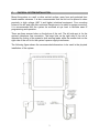
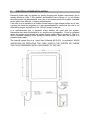
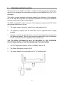
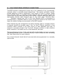
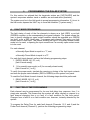
Microtel Series 200 Dialer
Installation and Operation Manual
P/N 310162 Rev C
CAUTION: Do not ship product with battery installed.
Proprietary Notice: This document and the subject matter hereto are the
property of MICROTEL, Inc. and shall not be reproduced or copied or
used for the purpose of manufacturing or sale of apparatus, except by
written permission of MICROTEL, Inc.
MICROTEL
206 West Judge Perez Drive
Chalmette, Louisiana 70043
Phone:
Fax:
504/276-0571
504/276-0574
http://www.Microtel-Inc.Com
e-mail: [email protected]
ii
MSC-250 INSTALLATION AND OPERATION MANUAL
TABLE OF CONTENTS
PAGE
I.
Introduction
A. General Information..................................................................................... 1
B. Unpacking and Incoming Inspection............................................................ 2
C. Physical System Mounting.....................................................................….. 3
D. Battery Installation....................................................................................... 4
E. Power Installation......................................................................……………. 5
F. Telephone Line Installation.......................................................................... 6
G. Fault Monitoring Interface.....................................................…………….…. 7
H. Powering Up the System..............................................................................8
II.
Programming the Dialer System
A. Fault Mode........................................................................………………….. 9
B. Fault Delay Time...............................................................………………….. 9
C. Fault Messages..........................................................................................10
D. Station Identification Messages........................................................…….. 11
E. Programming Telephone..................................……………………………..12
F. Operational Parameters .................................…………………………….. 12
1. Ring Count.....................……………................................................... 12
2. Tone or Pulse Dial Selection..........................................................…. 13
3. Message Repetitions.......................................................................... 13
4. Intercall Delay..................................................................................... 13
5. Delayed Run……………….................................................................. 14
III.
Operations
A. System Familiarization and Key Function Summary.................................. 15
B. Putting the Unit in Run....…….................................................................... 16
C. Receiving an Alarm.................................................................................... 17
D. Test and Advanced Keystroke Sequence.................................................. 18
IV.
Maintenance and Troubleshooting
A. Maintenance…………….............................................................................19
B. System Specifications................................................................................ 20
C. Product Warranty....................................................................................... 21
D. Vocabulary List…...................................................................................... 22
E. Vocabulary List Oil and Gas Industry........................................................ 23
iii
iv
I.
A.
INTRODUCTION
GENERAL INFORMATION
The purpose of this manual is to completely explain the function, installation, and
operation of the MCS Model 200 Communication System. This automatic dialing,
synthesized speech, telephone based monitoring system represents a new generation
of computer controlled telemetry devices, packed with features and capabilities not
found in any other telephone oriented monitoring system. The device is designed
specifically for industrial based equipment monitoring needs, by the engineering staff
which invented the concept of synthesized speech dialers.
The System is configured to accept four channels of normally open or normally closed
fault state switches (contacts), such as float switches, pressure switches, temperature
switches and similar devices that contain an unpowered contact that changes state
whenever a preset condition changes. Fault recognition can be set as fast as 1
second or as long as ninety-nine seconds, programmable on a channel-by-channel
basis. Internally, the system monitors its own power supply and will respond to any
power outage, which persists longer than a user programmable time period.
When an alarm occurs, as recognized by the system by the opening or closing of an
external contact, it begins to place a series of telephone calls, dialing up to eight
different telephone numbers, one at a time, in an attempt to make contact with a
qualified person to whom it can deliver a synthesized voice message, describing the
alarm condition. This message can be programmed by the user from an internal
system vocabulary of sixty five words, to uniquely describe the system location and
the alarm condition represented by each channel.
The system will continue to call from the list of up to 8 telephone numbers, insisting
that its message be heard. Also, if desired, the system can be called at any time to
check or verify the monitored conditions.
The following instructions generally describe the installation, operation and
maintenance of the equipment. Microtel reserves the right to make engineering
refinements that may not be described herein..
1
B.
UNPACKING AND INCOMING INSPECTION
Microtel takes all possible precautions in packaging each item to prevent shipping
damage. Carefully inspect each package at the time of receipt for signs of physical
damage. Report damage claims to the shipping agent involved immediately. Do not
install damaged equipment.
All instructions given on any attached labels or tags should be followed. Carefully
inspect all packing material before discarding it to prevent the loss of accessories,
mounting hardware, spare parts, or instructions.
If the unit is not to be installed immediately, repack it in the shipping carton to protect
it while in storage.
2
C.
PHYSICAL SYSTEM INSTALLATION
Mount the system on a wall or other vertical surface, away from and protected from
harsh weather extremes. It is also recommended that the unit not be placed in close
proximity to high voltage (480 V and higher) electrical equipment. Four mounting
holes on the left and right side enclosure flanges are to be used for system mounting.
It is recommended that the system be mounted at eye level to facilitate ease of
programming and operation.
There are three access holes on the bottom of the unit. The left side port is for the
system's telephone line connection. The large hole on the right side of the unit is
intended for routing of the system's fault sensing leads, while the smaller hole on the
right side of the unit is for the system's power supply transformer.
The following figure shows the recommended dimensions to be used in the physical
installation of the system.
3
D.
BATTERY INSTALLATION
The battery is installed at the bottom of the system, in the battery tray provided as
part of the interior chassis assembly.
IMPORTANT! Before installing the system battery, be certain the power supply
transformer is not plugged into an electrical outlet.
Remove the four phillips head screws which secure the system's front panel and
remove it to expose the system's interior. Note that the panel is still connected to the
system's main circuit board, so care must be exercised while the panel is hanging on
this "tether". Retrieve the red and black battery leads from within the battery tray.
Push the battery lead terminals on to the new battery, BEING CERTAIN that the red
lead connects to the positive (+) battery terminal, and the black lead connects to the
negative (-) battery terminal.
Slide (do not force) the battery completely into the battery tray with the terminals
pointed DOWN into the system. If the battery is not completely seated in the battery
tray, the front panel will be obstructed and will not fit properly onto its mounting area.
A new battery will take no longer than 24 hours to gain a full charge, capable of
powering the system through any power outage up to four hours in length. It should be
noted that the LOW BATTERY indicator is only valid when the 120 vac power is on. If
the LOW BATTERY indicator stays on for more than eight hours, the battery is in
need of replacement.
4
E.
ELECTRICAL POWER INSTALLATION
Electrical power may be applied by simply plugging the system transformer into a
nearby electrical outlet. If the system's environment has a history of, or has known
electrical power line disturbances, then use of a transient protection module, available
as on option from Microtel, is highly recommended.
If the unit is to be installed in a location where large or high voltage motors are in use,
a power line transient suppressor is also recommended to insure that the unit is not
affected by surges and spikes in the 120VAC power to the unit.
It is recommended that a separate circuit breaker be used with the system.
Remember that when the breaker is on, and the unit is plugged in, 12 vac is contained
within the system even though the system Power switch may be turned off. This is to
allow continued charging of the system's backup battery, even with the system in a
powered down state.
The internal system fuse is a 1 amp fuse (Littlefuse #312.001), or equivalent. WHEN
INSPECTING OR REPLACING THE FUSE, UNPLUG THE SYSTEM OR THROW
THE CIRCUIT BREAKER SUPPLYING POWER TO THE UNIT.
5
F.
TELEPHONE LINE INSTALLATION
The connection to the telephone network is a matter of simply plugging the modular jack
cable into the telephone line termination provided by the telephone utility (RJ-11C or
equivalent).
This section contains important information regarding the installation of the telephone
line to be used by the system, and pertinent information for notifying the telephone
company of what type of line is to be installed.
The MCS is registered for direct connection to the telephone network by the FCC, which
places three restrictions on its use:
1.
The system cannot connect to a party line or a pay telephone line.
2.
The telephone company must be notified that an FCC registered device is being
installed.
3.
If trouble is experienced with the device, it must be immediately disconnected form
the telephone network. Microtel must make any repairs which may be necessary
in order to maintain the FCC registration status of the device.
THE FOLLOWING INFORMATION WILL BE REQUIRED BY THE TELEPHONE
UTILITY WHICH INSTALLS THE TELEPHONE LINE FOR THE SYSTEM:
1.
The FCC Registration Number, which is, D4J6M6-13598-AL-E.
2.
The Ringer Equivalence, which is 0.2B.
3.
The system needs to be connected to an RJ-11C telephone jack.
6
G.
FAULT MONITORING INTERFACE CONNECTIONS
The MCS system is designed to accept up to four channels of dry (unpowered),
normally open or normally closed signal lines. The system provides a small,
pulsed sampling current to determine if the contact is open or closed. Leads
from normally open or normally closed switches may be routed through the
conduit port at the lower right side of the system. Connect each wire pair to its
appropriate channel input terminal pair on the Fault Input Terminal Strip.
Shielded, twisted pair, #20 or #22 wire (Belden 8205 or equivalent) is
recommended. If shielded cable is used, ground the shield at the sensor and
leave the shield floating (unconnected) at the MCS system.
Each channel may be configured to be either normally open or normally closed.
A channel should be normally open if the "no fault" (Green) condition is that
condition which consists of an open circuit on that channel's wire pair. A
channel is normally closed if the "no fault" (Green) condition is that condition
which consists of a closed circuit on that channel's wire pair.
The programming section of this manual will provide details on how to program
the Mode (normally open or normally closed) of each channel as well as setting
the Fault Delay time for each channel.
Any unused channel should be left unconnected and programmed to a normally
open mode.
.
7
H.
POWERING UP THE SYSTEM
NOTE: IF THE UNIT ABOUT TO BE POWERED UP FOR THE FIRST TIME
CONTAINS
HARDWARE
FOR
OPTIONAL
FEATURES,
READ
THE
SUPPLEMENTARY INSTRUCTION MANUAL FOR THOSE FEATURES BEFORE
POWERING THE UNIT UP FOR THE FIRST TIME.
After the system has been mounted in a suitable area, the battery installed and power,
telephone and fault sensing lines connected, it may be powered up by switching the
POWER switch to the ON position. This switch is on the system’s front panel. When
the unit is powered up, the front panel indicators will flash in sequence for a few
moments and the system will say “system ready”. If this does not happen, turn the
switch to the OFF position, disconnect the power and the telephone line from the unit.
Contact a qualified service person or Microtel, Inc. for instructions.
8
II.
PROGRAMMING THE DIALER SYSTEM
For this section, be advised that the keystroke entries are CAPITALIZED and the
system's responses whether visual or audible, are enclosed within [brackets].
The system must be in the Halt mode to accept programming information. If it is not in
the Halt mode, depress the HALT key to force that condition. ["system ready"]
A.
FAULT MODE PROGRAMMING
The fault status of each of the five channels is shown as a fault (RED) or no-fault
(GREEN) condition on the corresponding front panel indicator. The system allows the
user to specify whether an open contact condition should be regarded as a GREEN
(no fault), or as a RED (fault) state. To program each channel, first apply a no fault
contact state to each input. This means shorting the input if a normally closed contact
mode is to be used, or opening the input connections if a normally open contact mode
is to be used.
For each channel,
a Normally Open Mode is equal to a "1", and,
a Normally Closed Mode is equal to a "0".
For each fault input channel, perform the following programming steps:
1. ENTER, MODE, N(1,2,3, or 4)
[fault N mode ready]
2. 1 (for normally open mode) or 0 (for normally closed mode)
[fault N mode is (1 or 0)]
To verify the proper mode, simulate the opening or closing of the fault input contacts
and view the proper state indication (RED or GREEN) on the system front panel.
To read the Fault Mode for each channel, the following steps should be performed:
1. READ, MODE, N(1,2,3, or 4)
[fault N mode is (1 or 0)]
B.
FAULT DELAY TIME PROGRAMMING
Each channel may be programmed for its own fault delay time response, from 1 to
ninety-nine seconds. This means that the system will either display or respond to a
fault channel changing from a no fault to a fault condition for this time period.
Changes from a fault to a no fault condition are, however, instantly detected by the
system.
To program the Delay Time for each fault channel (Channels 1,2,3, and 4) and the
Power Fault channel (Channel 5), perform the following programming steps:
9
1. ENTER, DELAY, N(1,2,3,4, OR 5)
[fault N (or power fault) delay ready]
1.
XY (00 to 99) (seconds of delay)
[fault N (or power fault) delay is XY (00 to 99)
To verify the proper delay time, simulate the opening or closing of the fault input
contacts and view the proper state indication (RED or GREEN) on the system front
panel. The fault channel will change from a GREEN to a RED state after the
programmed delay. It will change from a RED to a GREEN state almost immediately.
To read the Fault Delay for each channel, the following steps should be performed:
1.
C.
READ, DELAY, N(1,2,3,4, or 5)
[fault N (or power fault) delay is XY (00 to 99)
FAULT MESSAGES
The system allows the user to program sentences up to eight words in length to be
spoken by the system identifying each fault condition. The unit is shipped with nonspecific phrases already programmed in. The system will articulate the channels as
"fault 1, fault 2,...and power fault". This programming operation may be used for all
channels, which are to be used by the system, or the pre-programmed, default phrases
may be used for any or all of the messages. The following programming steps should
be performed for the creation of fault channel messages:
1.
ENTER, MESSAGE, N (1,2,3,4, or 5) [message N ready]
2.
Enter the desired two digit word addresses from the system vocabulary lists
found in the appendix (each word selected will be spoken by the system following
its two digit entry).
3.
Terminate entry sequence with a second depression of ENTER
[message N is ...
(word1),(word2), (word3)...(word 8)]
To read or verify the message for each channel,
1.
READ, MESSAGE, N(1,2,3,4, or 5)
[message N is...(word1),(word2),(word3)...(word 8]
Status Only Channel Programming
Any fault channel may be programmed as a "status only" channel (i.e. it will not cause
call-outs to begin, but will be reported in any status messages). To program a channel
as a "status only" channel, program the word "tone" from the vocabulary list as the first
word in the fault message for that channel. The unit will make a "beep" sound after the
2-digit code for "tone" is entered. The remaining seven words identifying that channel
may then be entered as indicated above.
10
D.
STATION IDENTIFICATION
There are two ways to enter a station identification message into the system. The
station can be identified as a number up to eight digits in length, in which case the
system will refer to itself as, "this is station XX...X". Alternatively, the system will allow
the entry of up to sixteen words from system vocabulary, to be connected together
into one identification message. For instance, the station identification "This is the
east plant" is comprised of five words from the system's vocabulary. The first case is
called the Number Mode, while the later is referred to as the Message Mode of station
identification entry.
NUMBER MODE ENTRY OF STATION IDENTIFICATION MESSAGE
1.
ENTER, 0
[station number, ready]
2.
Enter desired digits, terminate the entire entry with a second depression of
ENTER
[the station number is xx...x]
To read the station number for verification,
1.
READ, 0
[the station number is xx...x]
MESSAGE MODE ENTRY OF STATION IDENTIFICATION MESSAGE
1.
ENTER, MESSAGE,O
[station identification, ready]
2.
Enter desired words by entering the appropriate two digit code for each word in
sequence from the vocabulary list found in the appendix. Terminate the entry
sequence with a second depression of ENTER.
[the station identification is ... (words), (word2), (word3)...(word 16)"]
To read the station identification message for verification,
1.
READ, MESSAGE,O
[the station identification is ...(word1),(word2), (word3)...(word 16)"]
11
E.
PROGRAMMING TELEPHONE NUMBERS
The system can be programmed with up to eight telephone numbers, which will be
called sequentially when an abnormal condition is detected by the system on any fault
channel not programmed as a "status only" channel. The following programming
procedure should be performed to enter telephone numbers into the system. Note that
there must be at least one telephone number programmed into the system for it to
operate at all. All eight telephone number data locations need not be programmed.
Telephone numbers may be deleted by entering a "0" into the data location for that
number in the list.
1.
ENTER,N (1,2,...8) [telephone number N, ready]
2.
Enter the desired phone number by depressing the numbers on the keypad.
The unit will repeat each number as you depress it.
3.
Terminate the entry with a second depression of ENTER [telephone number N
is nnn...n]
To read this data for verification,
1.
READ, N (1,2,...8)
[telephone number N is...nnn...n]
Up to 16 digits may be entered for each phone number position. If any of the numbers
the unit is to call require a pause for a second dial tone, enter the pause by using the
DELAY key in place of a digit.
To clear a phone number out of the unit, enter a 0 (zero) as the phone number. The
unit ignores any phone number that starts with a 0. If you wish to have the unit call the
operator, enter the phone number as DELAY, 0
F.
OPERATIONAL PARAMETERS
This section describes the procedure for setting 4 operational parameters. All of these
parameters are entered into the system using the system's programming keypad.
1.
Setting the Ring Count
The ring count is the number of rings the unit will wait before answering a call placed
to it. This may be set to any number of incoming rings from 1 to 99.
1.
2.
ENTER,
[ring count, ready]
enter a two digit number from 01 to 99 representing the desired ring count
[the ring count is XY]
To check the ring count programmed into the system,
1.
READ,
12
[the ring count is XY]
2.
Tone or Pulse Dial Selection
The system needs to be set for pulse or tone type dialing. Perform this selection by
following these programming steps. Before programming the unit to function in a tone
dialing mode, confirm with the telephone company that services the installation that
the line to which the unit is connected to will accept tone dialing.
1.
ENTER, MODE, 0
[telephone mode, ready]
2.
enter "0" for pulse type dialing, or “1” for tone type dialing
[telephone mode is X]
To verify the dialing mode,
1.
3.
READ,MODE, 0
[telephone mode is X]
Message Repetitions
The system will repeat its fault status message a number of times in the course of any
telephone call which it places. The system is shipped programmed to repeat the
message 8 times during each call.
If it is necessary to change this number,
perform the following programming steps.
1.
2.
ENTER, #
[message count, ready]
Enter a two digit number corresponding to the desired number of
message repetitions (01 to 99)
[the message count is xx]
To read and verify this data,
1.
4.
READ, #
[the message count is xx]
Intercall Delay
When a call place by the system is acknowledged (see section III.C. for the
acknowledgement procedure) it will delay further calls for a programmable period to
allow time for the condition to be corrected. This time delay period following an
acknowledged call is called the intercall delay. The unit is shipped with this delay set
to 1 hour. It may be from one to 99 hours and is programmed at the system keyboard
as follows.
13
1.
ENTER, DELAY, 0 [intercall delay, ready]
2.
Enter a two digit number corresponding to the desired number of hours of
delay
[the intercall delay is xx hours]
(Numbers less than 10 must be entered with a 0, as in 01, 05, etc.)
To read this data,
1. READ, DELAY, 0
[the intercall delay is xx hours]
5.
Delay Run Programming
The Run Mode may be entered after a programmable delay. To do so,
1. Depress DELAY, RUN
[system delay, ready] 2. Enter the desired two digit delay in minutes (01 to 99
minutes)
[the system delay is xx minutes]
(Values less than 10 minutes must be entered with a preceding 0, i.e. 01, 07...)
The flashing Run indicator verifies that the system is in the delayed run mode. After
the delay is completed, the system will enter the Run Mode and the Run indicator will
stay on.
14
III.
A.
OPERATIONS
SYSTEM FAMILIARIZATION AND KEY FUNCTION SUMMARY
The power switch for the system is located on the Front Panel of the system. It is
important to note that when 12 vac power is connected to the system, this switch does
not remove 12 vac power from the unit--it is always present unless the circuit breaker,
which the INSTALLER must supply, is turned off, or the transformer is removed from
the power outlet.
There are six indicators across the topside of the keyboard assembly on the front
panel. These LEDs will indicate the state of the fault channels which the system is
intended to monitor, indicating RED for a fault condition and GREEN for a no-fault
condition, along with a system status indicator which display RED for the HALT mode
and GREEN for the RUN mode.
On the left side of the system front panel, is the system speaker. This speaker allows
words the system synthesizes to be heard, as well as telephone line sounds when the
system is on the telephone line placing an alarm call.
A description of each of the system's keys and their functions now follows:
HALT
The HALT key will abort any operation in process, and return the system to the Halt
mode as indicated by the RUN STATUS indicator. In this mode, fault conditions will
not be acted upon by the system. However, it is still possible to call the system. The
system will answer the call and deliver the appropriate fault status message.
RUN
The RUN key will place the system in a run mode as indicated by the RUN STATUS
indicator. If fault conditions exist, the system will begin placing telephone calls (if
telephone numbers have been programmed into the system). Use of the Delay key in
conjunction with the RUN key will cause the system to execute a delayed entry into
the Run mode--which may be programmed to be up to 99 minutes (see the section
entitled "Putting the System in Run" later in this section for more information on this
feature).
MODE
The MODE key is used in conjunction with other keys to effect certain features in
system programming including fault modes and tone/dial selection.
SEQUENCE
The SEQUENCE key is a preface key, which allows some of the advanced operation
features of the system to be activated. Until the purpose and use of this key is explained
later in this manual, it is advisable to leave it alone. If this key is randomly operated with
others, a proper keystroke combination could occur, wiping out portions of
telephone number and other data.
ENTER
The ENTER key is used to enter data which the system must use in performing
its monitoring and alarming functions. Included in this data are telephone
numbers, fault messages, the system identification message, the message
count, and the intercall delay.
15
MESSAGE
The MESSAGE key is used in conjunction with others to program the message
for each fault channel, and the system identification message. Additionally,
depression of the message key alone when the system is in the Halt mode will
cause the current ID and status messages to be articulated by the system.
READ
The READ key is used to recall any of the programmed information.
DELAY
The DELAY key has four functions:
When used in telephone number programming, it inserts a short pause
between digits in a telephone number.
When used with the ENTER key,(i.e. ENTER, DELAY,O) it sets the intercall
delay time; that is, the time the system will wait after its callout message has
been acknowledged before it begins placing regular calls again (see section II
of this manual for additional information).
When the DELAY key is used with the RUN key, (DELAY, RUN) it allows
delayed, automatic entry into the Run mode.
When the DELAY key is used for fault delay time programming, it allows the
entry of integration or delay times for the detection of each fault condition.
DIGITS 1 THROUGH 0
The digits keys are used for numeric entry of data values and data locations.
* KEY
The * key is used as an entry location for ring count programming. The ring
count is the number of incoming telephone rings which the system will count
before answering and servicing the incoming call. (see Section II of this
manual for more information)
Additionally, the * key is the key used over the telephone for acknowledgement of the
system callout message. It is also useable locally (on the system keyboard) for
acknowledgement right at the system.
# KEY
The # key is used as an entry location for the message count. This is the number of
times that the entire fault status message is repeated in the course of each telephone
call placed by the system. (see Section II of this manual for more information)
B. PUTTING THE SYSTEM IN RUN
After all operational data has been entered into the system, the unit is ready to enter
the run mode, from which any fault channels will be acted upon--causing calls to be
placed to the programmed telephone numbers.
16
To place the system is the Run Mode, depress the RUN key on the system front panel.
The Run indicator will verify successful entry into the Run Mode.
Delayed Entry into the Run Mode
The Run Mode may be entered after a programmable delay. To do so,
1.
depress DELAY, RUN
[system delay, ready]
2.
enter the desired two digit delay in minutes (01 to 99 minutes)
[the system delay is xx minutes]
(values less than 10 minutes must be entered with a preceding 0, i.e. 01, 07...)
The flashing Run indicator verifies that the system is in the delayed runmode. After
the delay is completed, the system will enter the Run Mode and the Run indicator will
stay on.
C. RECEIVING AN ALARM
When a valid alarm condition is recognized by the system, it will be indicated locally
on the system front panel. If the system is in the Run Mode, it will immediately begin
placing telephone calls to the telephone numbers, which have been programmed by
the user.
Upon the receipt of an alarm call, the answering party will hear the station identification,
followed by the current status messages. This entire message will be repeated the
number of times programmed. If the entire message sequence is completed without an
acknowledgement being returned over the telephone link, the system will terminate the
call, wait 70 seconds for a call back acknowledgement, and then place a call to the next
telephone number in the list. If an acknowledgement is not received from the next call,
after the 70 second wait, a 3rd call will be placed, and so on. The unit will continue to
call repeatedly from the user's programmed list of telephone numbers indefinitely, until it
receives an acknowledgement or the fault condition is removed.
If the system is acknowledged during the call, it will not place any further calls for a time
programmed as the Intercall Delay. If a new fault condition occurs during that period,
the delay will abort and calls will begin again. If the entire delay expires and the fault
conditions still persist, the system will again begin to place telephone calls.
To Acknowledge a Call From the System
Acknowledgement may be accomplished by depressing the * key on the called
telephone between message repeats during the alarm call. The * key must be
depressed for at least 1 second but no longer than five seconds.
The system will
verify that the acknowledgement has been accepted by saying, [acknowledgement
accepted, the intercall delay is xx hours"].
If acknowledgement must be returned from a telephone without tone capability, the
system may be acknowledged by placing an immediate call back to the system,
17
within 60 seconds after it has completed its call. Again, the system will verify that the
acknowledgement has been accepted by saying, [acknowledgement accepted, the
intercall delay is xx hours].
D. TEST AND ADVANCED KEYSTROKE SEQUENCES
A number of sequence commands are possible on the system front panel keyboard.
These are as follows:
ARCHIVE DATA RECOVERY
SEQUENCE 40 [the number of calls placed by the system]
SEQUENCE 41 [the number of acknowledgements returned]
SEQUENCE 42 [the number of calls placed by the system]
SEQUENCE 43 the number of power faults]
SEQUENCE 44 [the number of resets or HALT key entries]
SYSTEM LEVEL TEST SEQUENCES
SEQUENCE 50 [vocabulary dump]
SEQUENCE 52 flash test all front panel indicators (HALT to terminate this sequence)
SEQUENCE 53 calculate internal memory checksum value
SEQUENCE 55 Acknowledge tone adjustment self test
PRESET ALL DATA VALUES TO DEFAULT
NOTE: Do not use these sequences unless you are thoroughly aware of the results,
which will occur--that is, the resetting of operational data to default values, and
destroying any numbers, messages, or delays, which may have been entered by the
user.
SEQUENCE 60 preset all messages to default (Fault 1, Fault 2, etc.)
SEQUENCE 61 preset telephone numbers only (all become 0) SEQUENCE 62 reset
all archive data to 0 values
18
IV
MAINTENANCE AND TROUBLESHOOTING
In the unlikely event that trouble is suspected with the system, it must be promptly
disconnected from the telephone network, and referred to Microtel or its authorized
service representatives. A service manual detailing troubleshooting procedures is
available to qualified personnel.
Periodically inspect the system internally for any evidence of moisture, blown fuses, or
battery failure as instructed herein.
A.
MAINTENANCE
1.
Battery Care
Battery life is dependant upon a number of factors, and will vary depending on the
number of outages, and the age of the battery. A new battery will take no longer than
24 hours to gain a full charge, capable of powering the system through any power
outage up to four hours in length. It should be noted that the LOW BATTERY indicator
is only valid when the 120 vac power is on. If the LOW BATTERY indicator stays on
for more than eight hours, the battery is in need of replacement.
2.
Battery Replacement
The battery is installed at the top of the system, in the battery tray provided as part of
the interior chassis assembly.
It is necessary to remove power from the system by throwing the supply circuit
breaker or removing the power transformer from the power outlet before replacing the
battery.
Refer to Section I.C - Battery Installation for instructions on installing a new battery.
3.
Volume Adjustment
The volume of the system's speech messages delivered to the telephone network is
fixed. The volume of the speech heard through the system speaker is, however,
adjustable by varying the setting of potentiometer R21, located on the main circuit card
in the unit.
4.
Acknowledge Tone Adjustment
R33, located on the system's main board, is the adjustment for the frequency detected
during the acknowledgement of an alarm call. By activating SEQUENCE 55 (see
previous section) the system will deliver a continuous acknowledge tone (* key) to
itself, during which the potentiometer R33 may be set. Center the adjustment by
varying the setting until the Acknowledge LED on the front panel turns on. There is
some amount of hysteresis associated with this detection so the centering of the
component must take into account approaches from each direction. The continuous
tone used for adjustment may be halted by depressing the HALT key after the
adjustment is completed.
19
B.
System Specifications
ENVIRONMENTAL
Temperature
Humidity
Surge
-10F to +12OF
90% RH, Non-condensing
2500 V, Per ANSI
C37-90A-1974, common and
differential mode
per FCC part 15C
EMI/RFI
ELECTRICAL
Power requirements
Fault sensing current
Battery Backup
Power outage detection time
120 VAC, 50/60 Hz, 7 watts
Less then 10 mA per channel
4 hours typical
1-99 seconds
PHYSICAL
Dimensions
Weight
Mounting method
Enclosure
11 5/8 x 9 7/16 x 4 inches
10 lbs.
Flange mount, 4 points
NEMA 12 std., others optional
TELEPHONE SYSTEM
FCC registered for direct interconnect
FCC Registration Number:
D4J6M6-13598-AL-E
Dialing capacity
8 numbers, 16 digits each,
maximum
Loop disconnect, 10 pps
nominal; or tone,
100ms/100ms; user
selectable
Programmable, 1 to 99 rings
Programmable, 1 to 99 hours
One Minute
Per FCC part 68
Dialing format
Answer delay
Acknowledged intercall delay
Unacknowledged intercall delay
Surge and environmental protection
OPERATIONAL
Fault detection method
Normally open or closed,
selectable
One to 99 seconds
Name or number, user selectable
user programmable messages
One to 99, user programmable
Nonvolatile EEPROM
Local keyboard entry
Fault integration time constant
Station identification
Message repetitions
Data retention
Programming
20
SYSTEM DIAGNOSTICS
Audible indicators
Line monitor
Vocal status of all data, fault conditions
and parameters
Fault channels
Run status
Off hook
Incoming call
Power on
Battery condition
Intercall delay in progress
Successful acknowledgment
Visual indicators
C.
PRODUCT WARRANTY
We warrant to the original purchaser the Microtel unit manufactured by us to be free
from defects in material and workmanship under normal use and service. Our
obligation under this warranty shall be limited to the repair or exchange of any part or
parts which may thus prove defective under normal use and service within one year
from date of installation by the original purchaser, in no event shall this warranty apply
to equipment after the expiration of eighteen (18) months from date of shipping to the
original purchaser whether or not the equipment is installed and which our
examination shall disclose to our satisfaction to be defective. THIS WARRANTY IS
EXPRESSLY IN LIEU OF ALL OTHER WARRANTIES EXPRESSED OR IMPLIED
INLCUDING THE WARRANTIES OF MERCHANTABILITY AND FITNESS FOR USE
AND OF ALL OTHER OBLIGATIONS OR LIABILITIES ON OUR PART, AND WE
NEITHER ASSUME, NOR AUTHORIZE ANY OTHER PERSON TO ASSUME FOR
US, ANY OTHER LIABILITY IN CONNECTION WITH THE SALE OF THIS
MICROTEL UNIT OR ANY PART THEREOF WHICH HAS BEEN SUBJECT TO
ACCIDENT, NEGLIGENCE, ALTERATION, ABUSE, OR MISUSE. WE MAKE NO
WARRANTY WHATSOEVER IN RESPECT TO ACCESSORIES OR PARTS NOT
SUPPLIED BY US. THE TERM "ORIGINAL PURCHASER", AS USED IN THIS
WARRANTY, SHALL BE DEEMED TO MEAN THAT PERSON FOR WHOM THE
MICROTEL UNIT IS ORIGINALLY INSTALLED.
21
D.
MCS 200 VOCABULARY
WORD
ADDRESS
WORD
ADDRESS
ZERO
ONE
TWO
THREE
FOUR
FIVE
SIX
SEVEN
EIGHT
NINE
ACCEPTED
ACKNOWLEDGE
ALARM
AMMONIA
CHLORINE
COUNT
DELAY
DIOXIDE
DISCHARGE
EAST
EMERGENCY
FAILURE
FAULT
FIRE
FLOODING
FLOW
GAS
HIGH
HOURS
IDENTIFICATION
INTERCALL
INTRUSION
IS
00
01
02
03
04
05
06
07
08
09
10
11
12
13
14
15
16
17
18
19
20
21
22
23
24
25
26
27
28
29
30
31
32
LEAK
LEVEL
LIFT
LOW
MESSAGE
MODE
NORMAL
NORTH
NUMBER
OFF
ON
PLANT
POWER
PRESSURE
PUMP
READY
RESIDUAL
RING
SOUTH
STATION
STATUS
SULFER
SYSTEM
TELEPHONE
THE
THIS
TONE (beep)
VACUUM
WAIT (pause)
WATER
WELL
WEST
33
34
35
36
37
38
39
40
41
42
43
44
45
46
47
48
49
50
51
52
53
54
55
56
57
58
59
60
61
62
63
64
22
E.
MCS 200 VOCABULARY OIL AND GAS INDUSTRY
WORD
ADDRESS
WORD
ADDRESS
ZERO
ONE
TWO
THREE
FOUR
FIVE
SIX
SEVEN
EIGHT
NINE
ACCEPTED
ACKNOWLEDGE
ALARM
CALL
CLOSED
COMPRESSOR
CONTACTOR
COUNT
DELAY
DIFFERENTIAL
DISCHARGE
DOWN
EAST
EMERGENCY
ENTRY
FAILURE
FAULT
FILTER
FIRE
FLARE
FLOODING
FLOW
GAS
HEADER
HIGH
HOURS
H2S
IDENTIFICATION
INTERCALL
INTRUSION
IS
00
01
02
03
04
05
06
07
08
09
10
11
12
13
14
15
16
17
18
19
20
21
22
23
24
25
26
27
28
29
30
31
32
33
34
35
36
37
38
39
40
LEAK
LEASE
LEVEL
LOW
MESSAGE
MODE
NORMAL
NORTH
NUMBER
OFF
OIL
ON
OPEN
PLANT
POWER
PRESSURE
PUMP
READY
RING
SCRUBBER
SET POINT
SHUTDOWN
SOUTH
STATION
STATUS
SUCTION
SYSTEM
TANK
TELEPHONE
TEMPERATURE
THE
THIS
TONE (beep)
UNAUTHORIZED
VACUUM
VALVE
WAIT (pause)
WATER
WELL
WEST
41
42
43
44
45
46
47
48
49
50
51
52
53
54
55
56
57
58
59
60
61
62
63
64
65
66
67
68
69
70
71
72
73
74
75
76
77
78
79
80
23