1
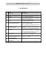
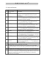
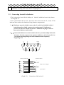
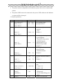
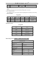
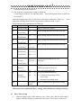
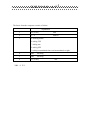
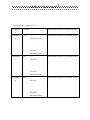
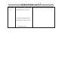
XK3190-A1+P
Weighing Indicator
USER’ S GUIDE
Attention:
Please read this User’s Guide carefully when you use
the indicator!
X K 3 1 9 0 - A 1+P
1 . Specifications
2 . Installation
2.1
Front & Back View of Indicator
2.2
Keyboard Function
2.3
Connecting Loadcell to Indicator
3. Calibration
4. Operating Instructions
4.1 Starting and Starting auto zero setting at turning on
4.2 Manual Zero Setting (Semi-automatically setting zero )
4.3 Tare Function
4.4 Connecting Scoreboard to Indicator
4.5 Connecting Pinter to Indicator
4.6 Connecting Serial Communication port to Indicator
4.7 Setting of Time and Date
4.8 Storing, Checking and Deleting of
Data
4.9 insufficient voltage indication
5. Maintenance and Announcements
6. Errors and Information
Important Notes!!!
1. Printer interface invalid due to the built-in micro-printer (optional supply upon
special requirement)
2. The function key is used as the paper roll key, it works upon pressing and stops
working upon releasing.
3. “5” should be chosen as printer parameter TypE
4. There is only one print format - linked bill format when micro-printer used.
5. The discount ratio printer option must be off while using:
“odE=0”
“dct=0”
X K 3 1 9 0 - A 1+P
1 Specification
1
Model
XK3190-A1+
2
Sample rated
5~25 times / sec
3
Load cell sensitivity
1~ 2mv/v
4
Division
5
Display
7-bits LED digital display 0.56” in character
height and 7 status indicating.
6
Clock
can display day/month/year and
second/minute/hour
7
Scoreboard display interface
Using serial output method :
1/2/5/10/20/50/100 optional
current loop signal, transmission distance ≤50m
RS323 signal, transmission distance ≤30m
8
Communication port
RS-232C
Baud rate: 600/1200/2400/4800/9600 optional
9
Printing Port
Standard parallel output port, can connect with
Tpup16 micro-printer, TM800,LX-300, KXP-
10
Power Supply
1121and LQ-1600k wide-line printer.
AC 187~242V ;
49~50Hz
The built-in repair-proof storage cell; 12V,7AH
0~40℃, ≤ 90% RH
11
Operating Temperature and
Relative Humidity
12
Storage /transportation
Temperature
-20 ~50℃
13
Fuse
500mA
X K 3 1 9 0 - A 1+P
2. Installation
2.1 Front & Back View of the Indicator
UNIT:KG
MONEY PRICE AUTO DATE TIME TARE STABLE
1
2
3
ACCU
PRE-T
FUN
4
5
6
TARE ENTER
0
CLEAR CHECK DATE STORE WEIGH
7
8
9
SET
CALB
TIME
PRINT
PRINT
(Graph 2-1) Front View of Indicator
* ACCU - accumulating
( 25 ) pins
Print output port
FUN- function
CALB – Calibrating
(15 ) pins
RS-232C; Scoreboard output port
( 9) pins
Loadcell input port
(Nameplate)
Power source
Fuse
(Graph 2-2) Back View of the Indicator
ZERO
X K 3 1 9 0 - A 1+P
2.2 Keyboard Function
1
2
3
4
5
6
7
8
9
10
11
12
13
14
Key
[ACCU],[ UNIT
PRICE]
Function
No meaning
In calibration mode, pressing [PRE-TARE/2] , can input
digital key “2”; In weighing mode, the key is used for
presetting tare.
[DELETE/4]
In calibration mode, pressing [DELETE/4], can input digital
key “4”; In weighing mode, it is deleting function key , more
details shown in episode “deleting”.
[CHECK/5]
In calibration mode, pressing [CHECK/5], can input digital
key “5”; In weighing mode, it is checking function key ,
more details shown in episode “checking”.
[DATE/6]
In calibration mode, pressing [DATE/6] can input digital
key “6” ;In weighing mode, it is date function key , more
details shown in episode “setting of time and date”.
[SET PRINT]
In calibration mode, pressing [SET PRINT] can input digital
key “7” ;In weighing mode, it is printing setup key , more
details shown in episode “printing function”.
[CALB/8]
In calibration mode, it is calibration function key ; In other
operation modes it only inputs digital key “8”
[TIME/9]
In calibration mode, pressing [TIME/9] can input digital key
“9” ;In weighing mode, it is time function key , more details
shown in episode “setting of time and date”.
[STORE/0]
In calibration mode, pressing [STORE/0] can input digital
key “0” ;In weighing mode, it is storing function key , more
details shown in episode “storing data”.
[ACCU/1],[ UNIT
In calibration mode, pressing [ACCU/1] or [ UNIT
PRICE/3]
PRICE/3] can input digital key, “1”; “3”;In weighing mode,
there are no meaning.
In weighing mode, when stable sign appears, press [TARE] key to clear tare. If
indicator displays zero, the weight value is net weight.
In weighing mode, when stable sign appeares, press [ZERO] key to clear limited
weight on the platform. You can set zero range , generally the zero range is 4% of full
scale.
In weighing mode, when stable sign appears, press [PRINT] key to print weight data.
In calibration mode, press [ENTER] key to confirm that parameters have been inputted
and will enter to next parameter setting automatically. When indicator is in date, time,
printing and communication setting mode, push [ENTER] key to confirm that
parameters have been inputted.
X K 3 1 9 0 - A 1+P
15
In calibration or parameters setting mode, pressing [weigh], it will exit from original
calibration or setting mode and return to weighing mode.
2.3
Connecting Loadcell to Indicator
1. The 9-pin socket is used for the link-up of loadcell, which has been clearly shown
in the graph 2-3.
2. The 4-pin shielded cable is used, +S must be short connected with +E, -S and -E. The
indicator does not have the function of long distance compensation.
3. ▲ !Indicator must be reliably connect ed to Loadcell and shielded-cable of
loadcell must be reliably connect ed to underground . If indicator is
powered on, the user should not insert or withdraw the plug in order to
protect the indicator and loadcell.
4. ▲ !Sensor and indicator are static sensitive devices; you must adopt anti-static
measures. In order to protect the operator ,indicator, and relevant devices,
you should install lightning rod in the thunderstorm frenquently
happening area.
-E
-S
1
2
Shield
3
4
5
6
7
8
9
+E
+S
-IN
+IN
Terminal of Indicator
Terminal of Sensor
+
6 +E
7 +S
Bridge of Power Supply
_
2 -S
1 -E
9 +IN
Signal Output
8 -IN
5 Shield
(Graph 3-2 )
Connection of the load cell
X K 3 1 9 0 - A 1+P
3. Calibration
According to the Graph 2-3, connecting Indicator and loadcell, and the indicator enters
weighing mode.
1. Connecting calibration jumper to the 15- pin socket on the indicator back panel.
(There is a 15-pin plug in the packing carton with its 14-pin short connected with
15-pin. )
2. According to table 4-3, carry out calibration step by step.
Table 4 - 1
step
Operation
1 press [ CALB]
2
press [1 ] [0 ]
press [Enter ]
3
press [ 0 ]
press [ Enter ]
4
press [ 2 ] [ 3 ]
press [ Enter ]
5
press [ 3 ] [ 0 ]
[0][9][0]
6
7
press [ Enter ]
Display
[E
[E
** ]
10 ]
[ dc
[ dc
*]
0]
[pon XY ]
[ pon 23 ]
Explanation
after calibration jumper is inserted
Enter division value selecting
1/2/5/10/20/50/100/200
Example: 10
Enter decimal point (0 -4)
Example: without Decimal point 0
Enter Zero range
X: zero set range (1-5) it stands for
2% 4% 10% 20% 100% of F.S
Y: power on Zero set range it
Stands for (1-5)
2% 4% 10% 20% 100% of F.S
example 23
[F ***** ] Enter overload warning value when
inputting F value,and re-pressing
[ F 30090 ] [ Enter ] key, the calibration will begin.
directly pressing [ Enter ],will enter into
the tenth step. If pressing [ weighting ],
Indicator will return to weighing status.
Example: 30090
[ noLoAdn] Confirming Zero position. At this time
there is no load on the scale.Pressing
[Input] when the stable light is on.
X K 3 1 9 0 - A 1+P
step
8
9
10
Operation
press [ 1 ] [ 5 ]
[ 0 ] [0 ]
press [ Enter ]
press [ Enter ]
press [2] [0]
[0][0] [0]
press [ Enter ]
11 press [ Enter ]
press [ Enter ]
press [ Enter ]
12
press [ 1 ]
press [ Enter ]
13
press [ 1 ]
press [ Enter ]
14
press [ 0 ]
press [ Enter ]
15
Display
Explanation
[ A LoAd1] Loading weight ≥ 5% Max.。
[ d 1500 ] Example: 1500
After stable light is on, press [ Enter ]
key.
[ noLoAd ] Confirming zero position again.
[ ALoAd2 ] Reloading weight on scale ≥50% Max.
It is better that this loading weight is
[ 20000 ] near the F.S. Example: 20000
After stable light is on, press [ Enter ]
key.
[H xxxxxx ] H. L. td indicating three calibrating
[L yyyyy ] coefficients . Recording them for spare
[td
zzzz ] use.
[ Adr ** ]
[ Adr 01 ]
communication address (01-26)
Example: 1
[ bt
*]
[ bt
1]
Serial communication baud rate ( 0-4).
It respectively represents baud rate: 600,
1200, 2400, 4800, 9600.
Example: 1 (1200)
[ tF
[ tF
*]
0]
Weighing
mode
Serial communication Mode:
0- Continuous transmitting mode,
no receiving.
1- Command response mode,
Example: 0
Calibration End.
Note: At step 6, 7, 8, 9, if press [ Weighing ] key, you can enter next step.
H. L. td indicating three calibrating
coefficients .Recording them for spare use.
CAUTION!
When calibration is over, the calibration jumper must be pulled
X K 3 1 9 0 - A 1+P
out.
4. . Operating Instructions
4.1
4.2
Power on
1 When using AC power , power on , setting the ship- form switch at the back cover
of the indicator on “1” ; If using DC power , setting the ship- form switch at the
back cover of indicator on “1”, then pressing the recover switch, the indicator will
perform “999999 - 000000 ” selfchecking. And then enter weighing mode. Or
after pressing any key, self-checking stops and enters weighing mode
automatically.
2 When power on, if loading weight on the plat form of the scale deviates from the
zero point, but still within zero set range, Then indicator will set zero at power on
automatically. If the loading weight is over the zero range, you should adjust zero
point of scale or recalibrate and reset the indicator.
Manual zero setting:
1 In weighing mode, press [ Zero ] key. Indicator will perform zero-setting.
2 If displayed value deviates from zero point, but still within zero-range, pressing
[ Zero ] key is available. Otherwise, [ Zero ] key is invalid. (In this status, please
recalibrate or reset zero parameters)
3 Only when stability sign lamp is on, you are allowed to set zero operation.
4.3 Tare function
1 Normal Tare :
When Indicator at weighing status, and displaying positive weight stably.,press
[ Tare ] key, indicator will deduct the displayed weight value as tare weight..
Then indicator displays net weight as “ 0 ”. And Tare sign Lamp is on.
2 Preset tare:
When Indicator at weighing status, press [ Pre Tare ] key, indicator will display
[ P ***** ], Using digital key entering known tare weight value, then press
[ Enter ] key, the pre-tare is finished. At this time indicator displays net weight
RS232C
and
tare sign lamp is lighted.
RXD
TXD
GND
1
3
2
9
+OUT
10
5
4
11
12
6
13
-OUT(Connecting scoreboard)
8
7
14
15
Calibration control
X K 3 1 9 0 - A 1+P
(Graph 4-1) Serial Communication port and score display port
4.4
Connecting Scoreboard to Indicator
1. The display interface of scoreboard is 15-pin socket, which has been clearly shown
in the Graph 4-1.
2.
The scoreboard signal is 20mA continuous current loop, outputting in binary code, the baud
rate is 600.
4.5
Connecting Printer to Indicator
1. The print port adopts parallel output and 25-pin connecting socket, which has been
clearly shown in the Graph 4-3.
ST
1
14
D0
D1
D2
D3
D4
D5
D6
D7
2
3
4
5
6
7
8
9
15
16
17
18
19
20
21
BUSY
10
22
11
23
12
24
13
25
GND
2. Printing notes:
▲ You must set the printer before you use it.
▲ You must connect the indicator and the printer correctly. The wrong
connection will destroy indicator output interface or printer input interface, and
may even destroy the indicator or printer.
▲ Turning on the printer as following: connecting the line correctly first, turning on
the indicator power, and turning on the printer power finally.
Turning off the printer as following: turning off the printer power first, and then
turning off the indicator power, cutting off the line finally.
Wrong procedure may destroy the indicator or printer.
X K 3 1 9 0 - A 1+P
▲ The printer must be compatible to the indicator, please choose the recommended
printer.
▲ The printer GND can not be connected to the power GND, otherwise the indicator
or printer will be destroyed.
3. Set print parameters
step
1
operating
press [PRN Set ]
press [ 9 ] [ 7 ]
press [ Enter ]
2
press [ 0 ]
press [ Enter ]
3
press [ 2 ]
press [ Enter ]
4
press [ 0 ]
press [ Enter ]
5
press [ 3 ]
press [ Enter ]
6
Explanation
Enter printing setup
Input password 97
[ Auto 1]
Auto/ manual print
0: manual
1: Auto
Example: 0
[ Auto
0]
[ type
0]
[ type
2]
[ H-u
1]
[ H-u
0]
[ Arr
1]
[ Arr
3]
[ L 000.10 ]
press [ 1 ][ 0 ][ 0 ]
press [ Enter ]
7
Press[0]
Press[Enter]
8
display
[ P 00 ]
[ P 97 ]
Press[0]
[ L001.00 ]
[ ode
[ ode
*]
]
[ dct
*]
Selecting type of the printer.
0: print inhibited
1: TPup16TP (Eng. mode)
2: TIMES TM-800
3 National KX-P1121
4: EPSON LQ-1600K
Example: 2
Selecting print format
0: Record format
1: document format
Example:0
selecting document numbers
(1-3)
Example: 3
Selecting Auto-print lower
Limit.
L: must> 10e
Example: 1:00
0: doesn’t choose blank
filling mode
1: choose blank filling print
mode
0: doesn’t use discount
X K 3 1 9 0 - A 1+P
Press[Enter]
[ dct
End
]
1: use discount
Note:
You can use discount only when the blank filling mode is selected.
4. print and print format
Press [PRINT] key, you can print required weighing data according to print setting.
Record Format:
Weight Bill
Date 97-01-31
NO.
Time
Gross ( kg ) Tare ( kg ) Net ( kg ) Accumulating(kg)
0001
08.56.16
299.98
1
298.98
298.98
0002
09.00.09
299.98
2
297.98
596.96
0003
09.00.28
299.98
3
296.98
893.94
Document Format
Weight Bill
NO. :
Date :
Time :
Gross :
Tare :
Net :
Total :
Blank filling format (Compelet
007
96-09-25
09.03.21
299.98 ( kg )
9.98 ( kg )
290.00 ( kg )
2059.90 ( kg )
printing only in five sconds)
WEIGHT BILL
Fist bill for operator
SERIAL No.
123
DATE
1999-05-28
TIME
12.35.28
VEHICLE No.
CARGO No.
GROSS
1580
kg
TARE
80
kg
DISCOUNT
10
%
1350
kg
NET
X K 3 1 9 0 - A 1+P
REMARK
★ If setting the odE parameter to 1, you can perform the blank filling priting, at
this time the other
priting formats are invalid (Records format and document
format are invalid).
Method: pushing [print] key, if
dct
parameter is set to 1, it will display [BFL
**], inputting the discount rate and pushing [Input], it will print out the blank
filling report: if
dct
parameter is set to 0, it will print out the blank filling
report directly, ‘discount rate’ will be in blank.
★ The XK3190-A1 does not have the functions of truck No. and Article No.
administration. The blank filling format is in blank.
★ In blank filling format, the indicator can print out the report in 1 or 3 fold.
★ The user can contact with the local dealer if the user wants the customized blank
filling format.
4.6
Connecting
Serial Communication port to Indicator
1. Communication port adopts 15 pins socket which was shared with scoreboard. It
was shown on page 9 of User’s Guide for A1,the pin 6(RXD) is used to receive the
signal from the computer, the pin 7(TXD) is used to output the signal to computer.
2. Communication port adopts RS-232C, and all data are ASCII codes. Every group of
data consists of ten bits binary codes, The first bit is start bit. The tenth bit is stop
bit, the other
eight bits are data bits.
Mode of communication:
(1) Continues output mode
Indicator transmits current data of weight value (Gross or net weight).
(2).
Command mode
Every time Indicator receives command form the master computer, it transmits one
frame data. Master computer transmits command to indicator, the indicator responses and
transmits one frame weight value data.
3. Setting communication parameters
(1) Communication parameters
Communication parameters consist of communication address, baud rate and
X K 3 1 9 0 - A 1+P
communication mode parameters.
(2) The sequence of parameters setting as following:
Connecting the loadcell , the indicator enters into working mode which is shown in
the Graph 2-3.
Insert the setting jumper into 15-pin socket at the back of indicator. (There is a 15-pin
plug in the packing carton with its 14-pin shorte connected with 15-pin. ).
Setup communication parameters as following:
Step
1
Operation
Display
Press[CALB]
2
Explanation
Plug in calibration jumper
[E
**]
Don’t change this data and enter next step.
[dc
**]
Don’t change this data and enter next step.
[Pon
**]
Don’t change this data and enter next step.
Press[Enter]
3
Press[Enter]
4
Press[Enter]
5
Don’t change this data and enter next step.
Press[Enter]
[F
******]
Don’t change this data and enter next step.
Press[Enter]
Press[Enter]
[H *****]
[L *****]
[td **.**]
[A d r **]
[A d r01 ]
Communication address (01~26)
Example: 1
[bt
*]
[bt
1]
Baud rate of serial communication (0~4)
which represent baud rate of
600,1200,2400,4800,9600
[tF
[tF
*]
0]
6
7
Press[1]
Press[Enter]
8
Press[1]
Press[Enter]
9
Press[0]
Press[Enter]
10
Weighing
mode
Serial communication mode:
0- Continous transmitting mode,
unreceiving
1- command responding mode
End of communication parameters setting
( Please note the explanation. Don’t change other parameters setting carelessly )
4.7 Date, Time Set-up
(1) Under weighing status of the indicator, press [ Date ] key, and date sign lamp is
lighted. Indicator display original data at this time. If it is correct, then press
X K 3 1 9 0 - A 1+P
[ Enter] key or [weighing] key to exit. If it is incorrect, using digital keys enters
new date , then press [ Enter ] key.
(2) Under weighing status of the indicator, press [ Time ] key, and Time sign lamp is
lighted. Indicator display original Time data at this time. If it is correct, then press
[ Enter ] key or the [ weighing ] key to exit. If it is incorrect, using digital keys
enters new time data, then press [ Enter ] key.
4.8 Weight data store, check and clear
1 Data storing.
(1) After weighing display becoming stable, press [ Store ] key, At this time,
indicator will store weight value store into internal memory and accumulats it.
(2) At the same time, displaying [ LoAd ] for fifteen seconds to prompt operator.
(3) Negative or zero weight value can’t be stored.
(4) Indicator can store:total accumulated times. total accumulated weight value, and
200 groups of weighing records.
(5) When print control “Auto” is set to “ 1”, system not only auto-prints, but also
auto- stories and auto-accumulates weighing data.
2 Checking
Press [ Check ] key, to check the weight record data in internal memory of the Indicator.
Including: Total accumulating times, Total accumulating weight value, and every group of
weighing record.
Operating as following:
Step
1
2
Operating
Display
press [ Check ]
press [ Check ]
[ **** ]
[ H *** ]
press [ Check ]
[L ***** ]
press [ Check ]
[no 001]
press [ Check ]
press [ Check ]
press [ Check ]
press [ Check ]
press [ Check ]
[ dt **** ]
[ t **** ]
[A *****]
[P ***** ]
[n ******]
press [ check ]
………
[no 002 ]
………
Explanation
n=Total accumulating times
H=Total accumulating weight High 3
bits
L=Total accumulating
weight low 5 bits
First group of weighing
sign symbols record
Date (M.D)
Time (H.m)
Gross
Tare
Net
The second group of weighing
symbols record
sigh
☆ Checking ends, Indicator auto-returns to weighing mode, and using [weighing ] key,
you can quit checking mode.
X K 3 1 9 0 - A 1+P
3
Clear
Press [ clear ] key, can clean accumulating weight value or stored data.
Step
1
Operating
Display
Explanation
[ sure 0 ]
Selecting clear/not clear
0: no
1: yes
Example: 1
press [ Clear ]
2
press [ 1 ]
[ sure 1 ]
[ sure 1 ]
End
4.9 Insufficient voltage indicating
When the storage cell voltage is insufficient, the insufficient voltage lamp is on. At
this time the indicator will twinkle.You should set the ship-like switch at the back
cover of indicator to “0” to protect the storage cell. Continual using will result in the
further decreasing of the storage cell voltage, in this case the indicator will cut off the
storage cell supply.
5.
5.1
5.2
5.3
5.4
5.5
Maintenance and Announcements
To guarantee the clarity and using life, the indicator shouldn’t be placed directly under
sunshine and should be placed in the plain space .
The indicator should avoid dust pollution, vibration and moisture.
Loadcell should connect with indicator reliably, and the system should be connected into
ground properly. The indicator must be detected from high electrical fields.
▲ !In order to protect the operator ,indicator, and relevant device, you should
mount lightning rod in thunderstorm frequently happening area.
▲ !Loadcell and indicator are static sensitive devices, you must adopt antistatic measures.
It is strictly forbidden to clean the case of indicator with intensive solvents (for example:
benzene and nitro oils)
Liquid and electrical conducting particles should not poured onto the indicator, otherwise the
X K 3 1 9 0 - A 1+P
electronic components will be damaged and electric shock is likely to happen.
5.6 You should cut off power supply of indicator and relevant device before you pull-in and out
the connecting line of indicator and external device.
▲ !You must cut off power supply of the indicator , before you plug the
connecting line of the loadcell in and out.
▲ !You must cut off power supply of the indicator and the printer, before you
plug in connecting line of the printer.
▲ !You must cut off power supply of the indicator and the scoreboard, before
you plug connecting line of the scoreboard in and out.
▲ !You must cut off power supply of the indicator and the master computer,
before you pull connecting line of communication in and out.
▲ !You must cut off power supply of the indicator and external connecting
system, before you pull connecting line of control output in and out.
5.7 The user should return this indicator to our company for repair. Non-weighing
manufacturer should not repair it, or by yourself, otherwise further destruction may
occur.
5.8
5.9
From invoice date, the indicator has a total one-year free repair period. If any
non-artificially obstacle about the indicator occurs while under correct using conditions
within the period, the user is allowed to send the product with its guarantee card (of the
correct number) back to our corporation for free repair.
The indicator shouldn’t be taken apart, otherwise free guarantee will be cancelled.
6.
Errors and Information
6.1
Normal information
1
………
Wait a moment, and this is a normal display.
2
Prnt
Wait a moment, the data are being transmitted between indicator and
printer.
3
LoAd
Storing data, it will indicate for not less than 2 seconds to prompt
the operator.
4
6.2
--OF--
No meaning.
Error information indicating
1
Err
03
Overload warning
2
Err
10
Zero or Negative weight value,
3
Err
11
dissatisfing
4
Err
12
dissatisfing demands of the printer set.
5
Err
16
Date or Time is illegal.
can’t be stored.
demands of document format , or printing set is wrong.
X K 3 1 9 0 - A 1+P
6.3
Wrong setting information indicating
1
Err
13
Wrong setting of the division value .
2
Err
14
Decimal point must be less than 5, please reset the decimal bit.
3
Err
15
Overload warning must be > 100, please reset it.
Err
6.4
1
17
Enter new data which
should be less than 65000.
Wrong connection information indicating
Err
P
It means the printer has trouble or is wrongly connected.
push any
key to quit.
2
Err
01
It means the load cell signal line is wrongly connected, or its signal is
negative.
(1) If this scale is under usage , then can be sure : the load cell connecting wires
had troubles, or load cell has been damaged.
(2) If this scale hasn’t been calibrated, the user should check the load cell’s
connective wires first. ( Whether the signal line has been negatively
connected). If the loadcell cable is corretly linked, but the indicator still
indicates Err01 , the problem can then be solved by short connecting pin 4
and pin 6.
3
Err
02
It means the load cell’s wires are wrongly linked, or the signal value
exceeds the A/D converting range.
(1) If this scale is under usage, then can be sure: the load cell’s connective wires
had troubles, or load cell is damaged.
(2) If this scale hasn’t been calibrated, please check as following:
a) Carefully check the load cell’s connective wires is right or not.
b) Check if load cell is suitable or not: It should satisfy the following terms: the
“scale’s dead load + scale’s rated capacity ” must be less than the load cell’s
rated capacity.
c) This may happen in case that there are more than one load cell in the weighing
system.
d) Short connecting the pin 4 and pin 1 on the socket of the load cell.
6.5
1
Error of components and solving method
Err
18
Key board has problems, It will indicates for ten seconds, then
indicator enters weighing mode.
2
Err
20
The data is partly lost in RAM. Operator should put in the calibration
plug to self-check, and then pull it out.
X K 3 1 9 0 - A 1+P
3
Err
21
Calibrating data have been lost in RAM and EPROM, Operator must
put
in the calibration plug, then reenter the original calibration data, turn
on the indicator again or re-calibrate it.
4
Err
22
5
Err
23
6.6
1.
EPROM has been damaged.
RAM has been damaged.
Other information indicating
Err
24
In normal operation, you must pull off the calibration jumper.The
indicator is under normal operation, and the calibration jumper shouldn’t be put in. If
calibration is needed, the calibration jumper
should be put in at set-up. You should pull
out the calibration jump when turning off the indicator. If
calibration jump was inserted when turning on,
the indicator finds that the
it will display
Err 24 for 6 seconds
to
prompt the operator.
2
Err
25 Illegal software, or E2PROM was damaged
.
12
groups of date constitutes of a frame
Date No. in a frame
explanation
1
02 (X ON) ,
2
+
3
Weight date
4
Weight date
5
Weight date
6
Weight date
7
Weight date
8
Weight date
9
Decimal position, from right to left (0 – 4)
10
Checking XRL, higher 4 bits
11
Checking XRL, lower 4 bits
12
03 (X OFF)
or
start
-,
END
X K 3 1 9 0 - A 1+P
The frame from the computer consists of 6 data
explanation
1
02 (X ON)
start
2
A~Z
address
3
A: Shaking hands
B: asking GW
C: asking tare
D: asking NW
E: asking accumulated times and accumulated weight
4
XRL
checking
5
XRL
checking
6
03 (X OFF)
XRL = 2 ⊕3
end
X K 3 1 9 0 - A 1+P
The explanation of data No : 4 - n
Command
No data
Each frame consists of 6 groups of data
A
Command
GW:
B
+/-
Each frame consists of 14 groups of data
GW data (6 bits)
.
.
.
GW data
Decimal position
Command
Tare:
C
+/-
Each frame consists of 14 groups of data
Tare data
.
.
.
Tare data
Decimal position
Command
D
NW:
+/NW data
.
.
.
NW data
Decimal position
Each frame consists of 14 groups of data
X K 3 1 9 0 - A 1+P
Command
E
Accumulated times and weigh
Accumulated times (4 bits )
.
.
.
, (comma) separation mark
Accumulated weight (10 bits )
.
.
Decimal position
Each frame consists of 22 groups of data