1
DDCMP
Programmer’s Guide
DC 900-1343D
Simpact, Inc.
9210 Sky Park Court
San Diego, CA 92123
April 1999
Simpact, Inc.
9210 Sky Park Court
San Diego, CA 92123
(619) 565-1865
DDCMP Programmer’s Guide
© 1996 through 1999 Simpact, Inc. All rights reserved
Printed in the United States of America
This document can change without notice. Simpact, Inc. accepts no liability for any errors this
document might contain.
Freeway is a registered trademark of Simpact, Inc.
All other trademarks and trade names are the properties of their respective holders.
Contents
List of Figures
7
List of Tables
9
Preface
11
1
17
Introduction
1.1
Product Overview . . . . . . . . . . . . . . . . . . .
1.1.1 Freeway Server . . . . . . . . . . . . . . . . . .
1.1.2 Embedded ICP . . . . . . . . . . . . . . . . . .
1.2 Freeway Client-Server Environment . . . . . . . . .
1.2.1 Establishing Freeway Server Internet Addresses
1.3 Embedded ICP Environment . . . . . . . . . . . . .
1.4 Client Operations . . . . . . . . . . . . . . . . . . .
1.4.1 Defining the DLI and TSI Configuration . . . .
1.4.2 Opening a Session . . . . . . . . . . . . . . . .
1.4.3 Exchanging Data with the Remote Application .
1.4.4 Closing a Session . . . . . . . . . . . . . . . . .
1.5 DDCMP Product Overview. . . . . . . . . . . . . .
1.5.1 Software Description . . . . . . . . . . . . . . .
1.5.2 Hardware Description . . . . . . . . . . . . . .
2
.
.
.
.
.
.
.
.
.
.
.
.
.
.
.
.
.
.
.
.
.
.
.
.
.
.
.
.
.
.
.
.
.
.
.
.
.
.
.
.
.
.
.
.
.
.
.
.
.
.
.
.
.
.
.
.
.
.
.
.
.
.
.
.
.
.
.
.
.
.
.
.
.
.
.
.
.
.
.
.
.
.
.
.
.
.
.
.
.
.
.
.
.
.
.
.
.
.
.
.
.
.
.
.
.
.
.
.
.
.
.
.
.
.
.
.
.
.
.
.
.
.
.
.
.
.
.
.
.
.
.
.
.
.
.
.
.
.
.
.
.
.
.
.
.
.
.
.
.
.
.
.
.
.
DDCMP DLI Functions
2.1
Summary of DLI Concepts . . . . . . . . . . . .
2.1.1 Configuration in the Freeway Environment.
2.1.2 Normal versus Raw Operation . . . . . . . .
2.1.3 Blocking versus Non-blocking I/O. . . . . .
DC 900-1343D
17
17
19
21
21
22
22
22
23
23
23
23
23
24
25
.
.
.
.
.
.
.
.
.
.
.
.
.
.
.
.
.
.
.
.
.
.
.
.
.
.
.
.
.
.
.
.
.
.
.
.
.
.
.
.
.
.
.
.
.
.
.
.
.
.
.
.
26
26
27
27
3
DDCMP Programmer’s Guide
2.1.4 Buffer Management . . . . . . . . . . . . . . . . . . . . . . . .
2.2 Using the DLI in the Freeway DDCMP Environment . . . . . . . .
2.2.1 Initializing the DLI . . . . . . . . . . . . . . . . . . . . . . . .
2.2.2 DDCMP DLI Session Configuration . . . . . . . . . . . . . . .
2.2.3 Opening and Attaching DLI Sessions . . . . . . . . . . . . . .
2.2.4 Detaching and Closing DLI Sessions . . . . . . . . . . . . . . .
2.2.5 Error Reporting . . . . . . . . . . . . . . . . . . . . . . . . . .
2.3 Example DDCMP Call Sequences. . . . . . . . . . . . . . . . . . .
2.4 Overview of DLI Functions for DDCMP . . . . . . . . . . . . . . .
2.4.1 DLI Optional Arguments . . . . . . . . . . . . . . . . . . . . .
2.5 Overview of DDCMP Requests using Raw dlWrite . . . . . . . . .
2.5.1 Commands using Raw dlWrite . . . . . . . . . . . . . . . . . .
2.5.1.1 Configure Link Command . . . . . . . . . . . . . . . . .
2.5.1.2 Clear Link Statistics Command . . . . . . . . . . . . . .
2.5.1.3 Start Link Command . . . . . . . . . . . . . . . . . . . .
2.5.1.4 Stop Link Command . . . . . . . . . . . . . . . . . . . .
2.5.2 Information Requests using Raw dlWrite . . . . . . . . . . . .
2.5.2.1 Request Buffer Report . . . . . . . . . . . . . . . . . . .
2.5.2.2 Request Link Statistics Report . . . . . . . . . . . . . . .
2.5.2.3 Request Link Status Report. . . . . . . . . . . . . . . . .
2.5.3 Data Transfer using Raw dlWrite . . . . . . . . . . . . . . . . .
2.5.3.1 Send Normal Data . . . . . . . . . . . . . . . . . . . . .
2.6 Overview of DDCMP Responses using Raw dlRead . . . . . . . . .
2.6.1 Received Data . . . . . . . . . . . . . . . . . . . . . . . . . . .
2.6.1.1 Normal or Maintenance Data [0] . . . . . . . . . . . . .
2.6.1.2 Final Acknowledge of Data Transmitted [7]. . . . . . . .
2.6.1.3 Final Acknowledge of Start Link [9] . . . . . . . . . . . .
2.6.1.4 Final Acknowledge of Stop Link [11] . . . . . . . . . . .
2.6.2 Circuit Exceptions. . . . . . . . . . . . . . . . . . . . . . . . .
2.6.2.1 Retry Limit Exceeded [129] . . . . . . . . . . . . . . . .
2.6.2.2 Receiving Computer not Responding [131] . . . . . . . .
2.6.2.3 Receive Message Lost due to Buffer Unavailability [133] .
2.6.2.4 Carrier Restored [134] . . . . . . . . . . . . . . . . . . .
2.6.2.5 Disconnect (No DCD) [135] . . . . . . . . . . . . . . . .
2.6.2.6 DDCMP Start Received in RUN State [136] . . . . . . .
2.6.2.7 Received Message Too Large [138] . . . . . . . . . . . . .
4
.
.
.
.
.
.
.
.
.
.
.
.
.
.
.
.
.
.
.
.
.
.
.
.
.
.
.
.
.
.
.
.
.
.
.
.
.
.
.
.
.
.
.
.
.
.
.
.
.
.
.
.
.
.
.
.
.
.
.
.
.
.
.
.
.
.
.
.
.
.
.
.
.
.
.
.
.
.
.
.
.
.
.
.
.
.
.
.
.
.
.
.
.
.
.
.
.
.
.
.
.
.
.
.
.
.
.
.
28
28
29
29
32
32
32
33
35
37
40
41
41
42
42
43
44
44
45
46
47
47
48
49
49
49
50
50
50
51
52
52
52
52
52
52
DC 900-1343D
Contents
2.6.2.8 DDCMP Maintenance Message Received [140] . . . .
2.6.2.9 Control Message Received in Maintenance Mode [200]
2.6.2.10 Data Message Received in Maintenance Mode [201] . .
2.6.3 Confirmation Responses . . . . . . . . . . . . . . . . . . . .
2.6.4 Reports in Response to dlWrite Information Requests . . . .
3
.
.
.
.
.
.
.
.
.
.
.
.
.
.
.
.
.
.
.
.
DDCMP Link Configuration Options
3.1
3.2
Data Rate Option . . . . . .
Clock Source Option . . . .
3.2.1 External . . . . . . . . .
3.2.2 Internal . . . . . . . . .
3.3 Reply Timer Length Option.
3.4 Line Mode Option. . . . . .
3.5 DDCMP Version Option . .
3.6 Electrical Interface Option .
3.7 Maintenance Mode Option .
.
.
.
.
.
.
.
.
.
.
.
.
.
.
.
.
.
.
.
.
.
.
.
.
.
.
.
53
53
53
53
53
55
.
.
.
.
.
.
.
.
.
.
.
.
.
.
.
.
.
.
.
.
.
.
.
.
.
.
.
.
.
.
.
.
.
.
.
.
.
.
.
.
.
.
.
.
.
.
.
.
.
.
.
.
.
.
.
.
.
.
.
.
.
.
.
.
.
.
.
.
.
.
.
.
.
.
.
.
.
.
.
.
.
.
.
.
.
.
.
.
.
.
.
.
.
.
.
.
.
.
.
.
.
.
.
.
.
.
.
.
.
.
.
.
.
.
.
.
.
.
.
.
.
.
.
.
.
.
.
.
.
.
.
.
.
.
.
.
.
.
.
.
.
.
.
.
.
.
.
.
.
.
.
.
.
.
.
.
.
.
.
.
.
.
.
.
.
.
.
.
.
.
.
.
.
.
.
.
.
.
.
.
.
.
.
.
.
.
.
.
.
55
57
57
57
57
58
58
58
58
A
Error Codes
59
B
DLI and TSI Configuration Process
61
C
Packet Exchange Quick Reference
67
C.1
C.2
C.3
C.4
C.5
C.6
C.7
C.8
C.9
C.10
C.11
C.12
C.13
C.14
Application Sequence of Events.
Command Sequences . . . . . .
attach-packet. . . . . . . . . . .
link-config-packet . . . . . . . .
start-link-packet . . . . . . . . .
write-data-packet . . . . . . . .
receive-data-packet . . . . . . .
stop-link-packet . . . . . . . . .
detach-packet . . . . . . . . . .
clr-stats-packet. . . . . . . . . .
clr-stats-ack-packet . . . . . . .
buf-report-packet . . . . . . . .
buf-report-ack-packet . . . . . .
stats-rpt-packet . . . . . . . . .
DC 900-1343D
.
.
.
.
.
.
.
.
.
.
.
.
.
.
.
.
.
.
.
.
.
.
.
.
.
.
.
.
.
.
.
.
.
.
.
.
.
.
.
.
.
.
.
.
.
.
.
.
.
.
.
.
.
.
.
.
.
.
.
.
.
.
.
.
.
.
.
.
.
.
.
.
.
.
.
.
.
.
.
.
.
.
.
.
.
.
.
.
.
.
.
.
.
.
.
.
.
.
.
.
.
.
.
.
.
.
.
.
.
.
.
.
.
.
.
.
.
.
.
.
.
.
.
.
.
.
.
.
.
.
.
.
.
.
.
.
.
.
.
.
.
.
.
.
.
.
.
.
.
.
.
.
.
.
.
.
.
.
.
.
.
.
.
.
.
.
.
.
.
.
.
.
.
.
.
.
.
.
.
.
.
.
.
.
.
.
.
.
.
.
.
.
.
.
.
.
.
.
.
.
.
.
.
.
.
.
.
.
.
.
.
.
.
.
.
.
.
.
.
.
.
.
.
.
.
.
.
.
.
.
.
.
.
.
.
.
.
.
.
.
.
.
.
.
.
.
.
.
.
.
.
.
.
.
.
.
.
.
.
.
.
.
.
.
.
.
.
.
.
.
.
.
.
.
.
.
.
.
.
.
.
.
.
.
.
.
.
.
.
.
.
.
.
.
.
.
.
.
.
.
.
.
.
.
.
.
.
.
67
68
69
70
72
73
74
76
77
78
79
81
82
84
5
DDCMP Programmer’s Guide
C.15 stats-rpt-ack-packet . . . . . . . . . . . . . . . . . . . . . . . . . . . . .
C.16 status-rpt-packet . . . . . . . . . . . . . . . . . . . . . . . . . . . . . . .
C.17 status-rpt-ack-packet . . . . . . . . . . . . . . . . . . . . . . . . . . . .
Index
6
85
87
88
91
DC 900-1343D
List of Figures
Figure 1–1: Freeway Configuration. . . . . . . . . . . . . . . . . . . . . . . . . . . .
18
Figure 1–2: Embedded ICP Configuration . . . . . . . . . . . . . . . . . . . . . . . .
19
Figure 1–3: A Typical Freeway Server Environment . . . . . . . . . . . . . . . . . . .
22
Figure 2–1: DLI Configuration File for Two DDCMP Links (Freeway Server) . . . . .
30
Figure 2–2: DLI Configuration File for Two Embedded ICP Links (DLITE Interface)
31
Figure 2–3: “C” Definition of DLI Optional Arguments Structure . . . . . . . . . . .
37
Figure 2–4: Configure Link Command CONFIG_TYPE Data Structure . . . . . . . .
41
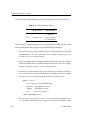
Figure B–1: DLI and TSI Configuration Process . . . . . . . . . . . . . . . . . . . . .
65
Figure C–1: “C” Structure for Configure Link Packet . . . . . . . . . . . . . . . . . .
70
Figure C–2: Link Statistics Report Format . . . . . . . . . . . . . . . . . . . . . . . .
80
Figure C–3: Buffer Report Format . . . . . . . . . . . . . . . . . . . . . . . . . . . .
83
Figure C–4: Link Statistics Report Format . . . . . . . . . . . . . . . . . . . . . . . .
86
Figure C–5: Link Status Report Format. . . . . . . . . . . . . . . . . . . . . . . . . .
89
DC 900-1343D
7
DDCMP Programmer’s Guide
8
DC 900-1343D
List of Tables
Table 2–1:
Include Files . . . . . . . . . . . . . . . . . . . . . . . . . . . . . . . . .
26
Table 2–2:
DLI Call Sequence for DDCMP (Blocking I/O) . . . . . . . . . . . . . .
33
Table 2–3:
DLI Call Sequence for DDCMP (Non-blocking I/O) . . . . . . . . . . .
34
Table 2–4:
DLI Functions: Syntax and Parameters (Listed in Typical Call Order) . .
36
Table 2–5:
Required dlWrite Optional Arguments Fields . . . . . . . . . . . . . . .
38
Table 2–6:
Relevant dlRead Optional Arguments Fields . . . . . . . . . . . . . . . .
39
Table 2–7:
Categories for DDCMP dlWrite Requests. . . . . . . . . . . . . . . . . .
40
Table 2–8:
Buffer Report Definition . . . . . . . . . . . . . . . . . . . . . . . . . . .
44
Table 2–9:
Link Statistics Report Definition . . . . . . . . . . . . . . . . . . . . . .
45
Table 2–10: Link Status Report Definition . . . . . . . . . . . . . . . . . . . . . . . .
46
Table 2–11: DDCMP Response Codes . . . . . . . . . . . . . . . . . . . . . . . . . .
48
Table 2–12: Received Data: pOptArgs.iProtModifier Field Values . . . . . . . . . . .
49
Table 2–13: Circuit Exceptions: pOptArgs.iProtModifier Field Values . . . . . . . . .
51
Table 3–1:
DDCMP Link Configuration Options and Settings . . . . . . . . . . . .
56
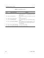
Table A–1:
DDCMP Error Codes . . . . . . . . . . . . . . . . . . . . . . . . . . . .
60
Table B–1:
Configuration File Names . . . . . . . . . . . . . . . . . . . . . . . . . .
62
Table C–1:
Values for iProtModifier Field . . . . . . . . . . . . . . . . . . . . . . . .
75
DC 900-1343D
9
DDCMP Programmer’s Guide
10
DC 900-1343D
Preface
Purpose of Document
This document describes the operation and programming interface required to use
Simpact’s Digital Data Communications Message Protocol (DDCMP) product, which
is a point-to-point serial line protocol. The DDCMP software runs on either a Simpact
Freeway communications server or on a Simpact embedded ICPs. The DDCMP implementation complies with the DDCMP Specification, version 4.0, AA-D599A-TC (with
a configuration option to use version I2).
Note
In this document, the term “Freeway” can mean either a Freeway
server or an embedded ICP. For the embedded ICP, also refer to
the user’s guide for your ICP and operating system (for example,
the ICP2432 User’s Guide for Windows NT).
Intended Audience
This document should be read by programmers who are interfacing a client application
program to Simpact’s DDCMP product running on Freeway. You should understand
the Freeway data link interface (DLI), as explained in the Freeway Data Link Interface
Reference Guide, and be familiar with the communication message formats required by
the DDCMP protocol.
DC 900-1343D
11
DDCMP Programmer’s Guide
Required Equipment
The DDCMP product requires the following major hardware components to operate:
•
a Freeway communications server or an embedded ICP that runs the communications software
•
a client computer that runs the following:
•
•
TCP/IP (for a Freeway server)
•
the user application program
Data link interface (DLI)
Organization of Document
Chapter 1 is an overview of Freeway and the DDCMP product.
Chapter 2 describes how to use the data link interface (DLI) between the client application program and the DDCMP communications software running on the Freeway ICP.
Chapter 3 describes the link configuration options available on the DDCMP software
package.
Appendix A describes error handling and lists the DDCMP error codes.
Appendix B is an overview of the configuration process for DLI sessions and TSI connections.
Appendix C provides detailed command and response header formats.
12
DC 900-1343D
Preface
3/31/99 Leslie:
Add DC-9001574, BitStream
Simpact References
The following documents provide useful supporting information, depending on the
customer’s particular hardware and software environments. Most documents are
available on-line at Simpact’s web site, www.simpact.com.
General Product Overviews
•
•
•
•
Freeway 1100 Technical Overview
25-000-0419
Freeway 2000/4000/8800 Technical Overview
25-000-0374
ICP2432 Technical Overview
25-000-0420
ICP6000X Technical Overview
25-000-0522
Hardware Support
•
•
•
•
•
•
•
•
•
•
Freeway 1100/1150 Hardware Installation Guide
DC 900-1370
Freeway 1200 Hardware Installation Guide
DC 900-1537
Freeway 1300 Hardware Installation Guide
DC 900-1539
Freeway 2000/4000 Hardware Installation Guide
DC 900-1331
Freeway 8800 Hardware Installation Guide
DC 900-1553
Freeway ICP6000R/ICP6000X Hardware Description
DC 900-1020
ICP6000(X)/ICP9000(X) Hardware Description and Theory of
Operation
DC 900-0408
ICP2424 Hardware Description and Theory of Operation
DC 900-1328
ICP2432 Hardware Description and Theory of Operation
DC 900-1501
ICP2432 Hardware Installation Guide
DC 900-1502
Freeway Software Installation Support
•
•
•
•
•
•
•
•
Freeway Software Release Addendum: Client Platforms
DC 900-1555
Freeway User’s Guide
DC 900-1333
Getting Started with Freeway 1100/1150
DC 900-1369
Getting Started with Freeway 1200
DC 900-1536
Getting Started with Freeway 1300
DC 900-1538
Getting Started with Freeway 2000/4000
DC 900-1330
Getting Started with Freeway 8800
DC 900-1552
Loopback Test Procedures
DC 900-1533
DC 900-1343D
13
DDCMP Programmer’s Guide
Embedded ICP Installation and Programming Support
•
•
•
•
•
ICP2432 User’s Guide for Digital UNIX
DC 900-1513
ICP2432 User’s Guide for OpenVMS Alpha
DC 900-1511
ICP2432 User’s Guide for OpenVMS Alpha (DLITE Interface)
DC 900-1516
ICP2432 User’s Guide for Windows NT
DC 900-1510
ICP2432 User’s Guide for Windows NT (DLITE Interface)
DC 900-1514
Application Program Interface (API) Programming Support
•
•
•
Freeway Data Link Interface Reference Guide
DC 900-1385
Freeway Transport Subsystem Interface Reference Guide
DC 900-1386
QIO/SQIO API Reference Guide
DC 900-1355
Socket Interface Programming Support
•
Freeway Client-Server Interface Control Document
DC 900-1303
Toolkit Programming Support
•
Freeway Server-Resident Application and Server Toolkit Program- DC 900-1325
mer’s Guide
•
•
OS/Impact Programmer’s Guide
DC 900-1030
Protocol Software Toolkit Programmer’s Guide
DC 900-1338
Protocol Support
•
•
•
•
•
•
•
•
•
•
14
ADCCP NRM Programmer’s Guide
DC 900-1317
Asynchronous Wire Service (AWS) Programmer’s Guide
DC 900-1324
Addendum: Embedded ICP2432 AWS Programmer’s Guide
DC 900-1557
AUTODIN Programmer’s Guide
DC 908-1558
Bit-Stream Protocol Programmer’s Guide
DC 900-1574
BSC Programmer’s Guide
DC 900-1340
BSCDEMO User’s Guide
DC 900-1349
BSCTRAN Programmer’s Guide
DC 900-1406
DDCMP Programmer’s Guide
DC 900-1343
FMP Programmer’s Guide
DC 900-1339
DC 900-1343D
Preface
•
•
•
•
•
•
Military/Government Protocols Programmer’s Guide
DC 900-1602
SIO STD-1200A (Rev. 1) Programmer’s Guide
DC 908-1359
SIO STD-1300 Programmer’s Guide
DC 908-1559
X.25 Call Service API Guide
DC 900-1392
X.25/HDLC Configuration Guide
DC 900-1345
X.25 Low-Level Interface
DC 900-1307
Document Conventions
This document follows the most significant byte first (MSB) and most significant word
first (MSW) conventions for bit-numbering and byte-ordering. In all packet transfers
between the client applications and the ICPs, the ordering of the byte stream is preserved. However, DDCMP packed data contains word values that are not byteswapped.
The term “Freeway” refers to any of the Freeway server models (for example, Freeway
1100/1150/1200/1300, Freeway 2000/4000, or Freeway 8800), or to the embedded ICP
product (for example, the embedded ICP2432).
Physical “ports” on the ICPs are logically referred to as “links.” However, since port and
link numbers are usually identical (that is, port 0 is the same as link 0), this document
uses the term “link.”
Program code samples are written in the “C” programming language.
Revision History
The revision history of the DDCMP Programmer’s Guide, Simpact document
DC 900-1343D, is recorded below:
Revision
Release Date
DC 900-1343A
January 1996
DC 900-1343D
Description
Original release
15
DDCMP Programmer’s Guide
Revision
Release Date
DC 900-1343B
March 1998
Description
•
•
DC 900-1343C November 1998
•
•
•
DC 900-1343D
•
•
April 1999
•
•
Add new Freeway overview and Embedded ICP information (Section 1.2 through Section 1.5)
Changes to Chapter 2: minor changes to Section 2.2.3 on
page 32 and Section 2.3 on page 33, add dlpErrString
function (Table 2–4 on page 36), Stop Link DTR control
(Section 2.5.1.4 on page 43), and major changes to
Section 2.6 on page 48
Add maintenance mode configuration option
(Section 3.7 on page 58)
Minor changes to Appendix B
Changes to Chapter 2: add dlSyncSelect function
(Table 2–4 on page 36); correct maximum iBufLen
(Section 2.5.3.1 on page 47).
Add Appendix C, “Packet Exchange Quick Reference”
Remove appendix for the loopback test. This information is included in the Loopback Test Procedures document (for a Freeway server) or the user’s guide for your
embedded ICP and operating system (for example, the
ICP2432 User’s Guide for Windows NT).
Modify Chapter 2 and Appendix B for embedded ICP
users
Add Carrier Restored exception (Table 2–13 on page 51)
Customer Support
If you are having trouble with any Simpact product, call us at 1-800-275-3889 Monday
through Friday between 8 a.m. and 5 p.m. Pacific time.
You can also fax your questions to us at (619)560-2838 or (619)560-2837 any time.
Please include a cover sheet addressed to “Customer Service.”
We are always interested in suggestions for improving our products. You can use the
report form in the back of this manual to send us your recommendations.
16
DC 900-1343D
Chapter
1
Introduction
1.1 Product Overview
Most recent
modification
date:
8/18/98 Leslie:
minor mods.
Just update
when
convenient.
Simpact provides a variety of wide-area network (WAN) connectivity solutions for
real-time financial, defense, telecommunications, and process-control applications.
Simpact’s Freeway server offers flexibility and ease of programming using a variety of
LAN-based server hardware platforms. Now a consistent and compatible embedded
intelligent communications processor (ICP) product offers the same functionality as
the Freeway server, allowing individual client computers to connect directly to the
WAN.
Both Freeway and the embedded ICP use the same data link interface (DLI). Therefore,
migration between the two environments simply requires linking your client application with the proper library. Various client operating systems are supported (for example, UNIX, VMS, and Windows NT).
Simpact protocols that run on the ICPs are independent of the client operating system
and the hardware platform (Freeway or embedded ICP).
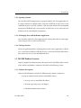
1.1.1 Freeway Server
Simpact’s Freeway communications servers enable client applications on a local-area
network (LAN) to access specialized WANs through the DLI. The Freeway server can be
any of several models (for example, Freeway 1100, Freeway 2000/4000, or Freeway
8000/8800). The Freeway server is user programmable and communicates in real time.
It provides multiple data links and a variety of network services to LAN-based clients.
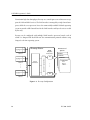
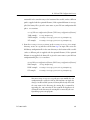
Figure 1–1 shows the Freeway configuration.
DC 900-1343D
17
DDCMP Programmer’s Guide
To maintain high data throughput, Freeway uses a multi-processor architecture to support the LAN and WAN services. The LAN interface is managed by a single-board computer, called the server processor. It uses the commercially available VxWorks operating
system to provide a full-featured base for the LAN interface and layered services needed
by Freeway.
Freeway can be configured with multiple WAN interface processor boards, each of
which is a Simpact ICP. Each ICP runs the communication protocol software using
Simpact’s real-time operating system.
Application DLI
n
Client n
Server
Processor
SCADA
Defense
ICP
Financial
Commercial
X.25
Bisync
HDLC . . .
ICP
3413
…
Client 2
Ethernet LAN
Application DLI
2
AAAA
AAAA
AA
AAAAAA
AAAA
AA
AAAAAA
AAAA
AA
AAAAAA
AAAA
AA
AAAAAA
Industry Standard Bus
Client 1
WAN Protocol
Options
WAN
Interface
Processors
…
Freeway Server
Application DLI
1
Figure 1–1: Freeway Configuration
18
DC 900-1343D
1: Introduction
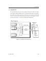
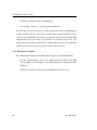
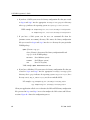
1.1.2 Embedded ICP
The embedded ICP connects your client computer directly to the WAN (for example,
using Simpact’s ICP2432 PCIbus board). The embedded ICP provides client applications with the same WAN connectivity as the Freeway server, using the same data link
interface. The ICP runs the communication protocol software using Simpact’s real-time
operating system. Figure 1–2 shows the embedded ICP configuration.
Client Computer
AAA
AA
AAA
AA
AAAAA
AAAAA
AAA
AA
AAA
AA
AAAAA
AAA
AA
AAAAA
AAA
AA
AAA
Industry Standard Bus
…
Application DLI
2
Simpact Driver
Application DLI
1
WAN Protocol
Options
SCADA
Embedded ICP
Defense
Commercial
X.25
Bisync
HDLC . . .
Simpact
WAN Protocol
Software
Financial
SWIFT
CHIPS
Telerate
Telekurs
Reuters
40+ Market
Feeds . . .
3414
Application DLI
n
Figure 1–2: Embedded ICP Configuration
DC 900-1343D
19
DDCMP Programmer’s Guide
Summary of product features:
•
Provision of WAN connectivity either through a LAN-based Freeway server or
directly using an embedded ICP
•
Elimination of difficult LAN and WAN programming and systems integration by
providing a powerful and consistent data link interface
•
Variety of off-the-shelf communication protocols available from Simpact which
are independent of the client operating system and hardware platform
•
Support for multiple WAN communication protocols simultaneously
•
Support for multiple ICPs (two, four, eight, or sixteen communication lines per
ICP)
•
Wide selection of electrical interfaces including EIA-232, EIA-449, EIA-485,
EIA-530, EIA-562, V.35, ISO-4903 (V.11), and MIL-188
•
Creation of customized server-resident and ICP-resident software, using
Simpact’s software development toolkits
•
Freeway server standard support for Ethernet and Fast Ethernet LANs running
the transmission control protocol/internet protocol (TCP/IP)
•
Freeway server standard support for FDDI LANs running the transmission control protocol/internet protocol (TCP/IP)
•
Freeway server management and performance monitoring with the simple network management protocol (SNMP), as well as interactive menus available
through a local console, telnet, or rlogin
20
DC 900-1343D
1: Introduction
1.2 Freeway Client-Server Environment
The Freeway server acts as a gateway that connects a client on a local-area network to a
wide-area network. Through Freeway, a client application can exchange data with a
remote data link application. Your client application must interact with the Freeway
server and its resident ICPs before exchanging data with the remote data link application.
One of the major Freeway server components is the message multiplexor (MsgMux)
that manages the data traffic between the LAN and the WAN environments. The client
application typically interacts with the Freeway MsgMux through a TCP/IP BSD-style
socket interface (or a shared-memory interface if it is a server-resident application
(SRA)). The ICPs interact with the MsgMux through the DMA and/or shared-memory
interface of the industry-standard bus to exchange WAN data. From the client application’s point of view, these complexities are handled through a simple and consistent
data link interface (DLI), which provides dlOpen, dlWrite, dlRead, and dlClose functions.
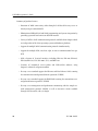
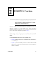
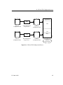
Figure 1–3 shows a typical Freeway connected to a locally attached client by a TCP/IP
network across an Ethernet LAN interface. Running a client application in the Freeway
client-server environment requires the basic steps described in Section 1.2.1 and
Section 1.4.
1.2.1 Establishing Freeway Server Internet Addresses
The Freeway server must be addressable in order for a client application to communicate with it. In the Figure 1–3 example, the TCP/IP Freeway server name is freeway2,
and its unique Internet address is 192.52.107.100. The client machine where the client
application resides is client1, and its unique Internet address is 192.52.107.99. Refer
to the Freeway User’s Guide to initially set up your Freeway and download the operating
system, server, and protocol software.
DC 900-1343D
21
DDCMP Programmer’s Guide
Freeway
Client
Application DLI TSI
TCP/IP
TCP/IP
Socket Interface
SRA
Msg
TSI Mux
client1
192.52.107.99
ICP0
ICP1
WAN
Protocols
ICP2
ICP3
3125
Shared Memory
Interface
Ethernet
Industry
Standard Bus
Client
freeway2
192.52.107.100
Figure 1–3: A Typical Freeway Server Environment
1.3 Embedded ICP Environment
Refer to the user’s guide for your embedded ICP and operating system (for example, the
ICP2432 User’s Guide for Windows NT) for software installation and setup instructions.
The user’s guide also gives additional information regarding the data link interface
(DLI) and embedded programming interface descriptions for your specific embedded
environment. Refer back to Figure 1–2 on page 19 for a diagram of the embedded ICP
environment. Running a client application in the embedded ICP environment requires
the basic steps described in Section 1.4
1.4 Client Operations
1.4.1 Defining the DLI and TSI Configuration
In order for your client application to communicate with the ICP’s protocol software,
you must define the DLI sessions and the transport subsystem interface (TSI) connections between your client application and Freeway (or an embedded ICP). To accomplish this, you first define the configuration parameters in DLI and TSI ASCII
configuration files, and then you run two preprocessor programs, dlicfg and tsicfg, to
create binary configuration files (see Appendix B). The dlInit function uses the binary
configuration files to initialize the DLI environment.
22
DC 900-1343D
1: Introduction
1.4.2 Opening a Session
After the DLI and TSI configurations are properly defined, your client application uses
the dlOpen function to establish a DLI session with an ICP link. As part of the session
establishment process, the DLI establishes a TSI connection with the Freeway MsgMux
through the TCP/IP BSD-style socket interface for the Freeway server, or directly to the
ICP driver for the embedded ICP environment.
1.4.3 Exchanging Data with the Remote Application
After the link is enabled, the client application can exchange data with the remote application using the dlWrite and dlRead functions.
1.4.4 Closing a Session
When your application finishes exchanging data with the remote application, it calls the
dlClose function to disable the ICP link, close the session with the ICP, and disconnect
from the Freeway server or the embedded ICP driver.
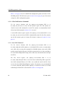
1.5 DDCMP Product Overview
Simpact’s Digital Data Communications Message Protocol (DDCMP) product consists
of the software and hardware components described in the following sections.
1.5.1 Software Description
Simpact’s DDCMP product includes the following major software components:
•
A group of communications software downloadable images:
1. Freeway server or embedded ICP software
2. Real-time operating system (OS/Impact)
3. DDCMP communications software
DC 900-1343D
23
DDCMP Programmer’s Guide
•
DLI library for linking with client applications
•
Test program (ddcmpalp.c) to check product installation
For a Freeway server, the Freeway User’s Guide describes the software installation procedures, and the Loopback Test Procedures describes how to run the loopback test program. For an embedded ICP, refer to the user’s guide for your particular embedded ICP
and operating system (for example, the ICP2432 User’s Guide for Windows NT). The
DLI provides an interface by which data is exchanged between the client application
and Freeway; refer to the Freeway Data Link Interface Reference Guide.
1.5.2 Hardware Description
The configuration of Simpact’s DDCMP product requires the following hardware:
•
Freeway communications server (for example, Freeway 1100, Freeway 2000,
Freeway 4000, or Freeway 8800) or a an embedded ICP (for example the PCIbus
ICP2432)
•
24
Ethernet connection to a client running TCP/IP (for a Freeway server)
DC 900-1343D
Chapter
2
Note
DDCMP DLI Functions
In this document, the term “Freeway” can mean either a Freeway
server or an embedded ICP. For the embedded ICP, also refer to
the user’s guide for your ICP and operating system (for example,
the ICP2432 User’s Guide for Windows NT).
This chapter describes how to use the data link interface (DLI) functions to write client
applications interfacing to the Freeway DDCMP protocol software. You should be
familiar with the concepts described in the Freeway Data Link Interface Reference Guide;
however, some summary information is provided in Section 2.1.
If you are using an embedded ICP, you must also refer to the user’s guide for your specific ICP and operating system regarding the embedded DLI interface (referred to as
DLITE).
The following might be helpful references while reading this chapter:
•
Section 2.3 compares a typical sequence of DLI function calls using blocking versus non-blocking I/O.
•
Appendix A explains error handling and provides a summary table for DDCMP
error codes. The Freeway Data Link Interface Reference Guide gives complete DLI
error code descriptions.
DC 900-1343D
25
DDCMP Programmer’s Guide
•
The Freeway Data Link Interface Reference Guide shows a generic code example
which can guide your application program development. The loopback test program (ddcmpalp.c) distributed with the product software is another example.
•
Appendix C provides detailed command and response header formats..
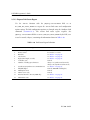
•
The various mnemonic codes mentioned throughout this document are defined
in the include files provided with this product, which are described in Table 2–1.
Table 2–1: Include Files
Description
Include File
DLI_PROT_* Codes
dliprot.h
DLI_ICP_ERR_* Codes
dlicperr.h
DLI_ICP_CMD_* Codes
dliicp.h
FW_* Codes
freeway.h
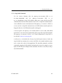
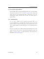
2.1 Summary of DLI Concepts
The DLI presents a consistent, high-level, common interface across multiple clients,
operating systems, and transport services. It implements functions that permit your
application to use data link services to access, configure, establish and terminate sessions, and transfer data across multiple data link protocols. The DLI concepts are
described in detail in the Freeway Data Link Interface Reference Guide. This section
summarizes the basic information.
2.1.1 Configuration in the Freeway Environment
Several types of configuration affect how a client application runs in the Freeway environment:
26
•
Freeway server configuration
•
data link interface (DLI) session configuration
DC 900-1343D
2: DDCMP DLI Functions
•
transport subsystem interface (TSI) connection configuration
•
protocol-specific ICP link configuration
The Freeway server is normally configured only once, during the installation procedures described in the Freeway User’s Guide. DLI session and TSI connection configurations are defined by specifying parameters in DLI and TSI ASCII configuration files
and then running two preprocessor programs, dlicfg and tsicfg, to create binary configuration files. Refer to Appendix B of this document, as well as the Freeway Data Link
Interface Reference Guide and the Freeway Transport Subsystem Interface Reference
Guide. You must perform ICP link configuration within the client application
(described in Section 2.5.1.1).
2.1.2 Normal versus Raw Operation
The Freeway Data Link Interface Reference Guide describes two types of DLI operation,
Normal and Raw. However, the DDCMP protocol requires Raw operation so that the
write (Section 2.5) and read (Section 2.6) requests can specify protocol-specific information. The embedded DLITE interface also requires Raw operation.
2.1.3 Blocking versus Non-blocking I/O
Note
Earlier Freeway releases used the term “synchronous” for blocking
I/O and “asynchronous” for non-blocking I/O. Some parameter
names reflect the previous terminology.
Non-blocking I/O applications are useful when doing I/O to multiple channels with a
single process where it is not possible to “block” on any one channel waiting for I/O
completion. Blocking I/O applications are useful when it is reasonable to have the calling process wait for I/O completion.
DC 900-1343D
27
DDCMP Programmer’s Guide
In the Freeway environment, the term blocking I/O indicates that the dlOpen, dlClose,
dlRead and dlWrite functions do not return until the I/O is complete. For non-blocking
I/O, these functions might return after the I/O has been queued at the client, but before
the transfer to Freeway is complete. The client must handle I/O completions at the software interrupt level in the completion handler established by the dlInit or dlOpen
function, or by periodic use of dlPoll to query the I/O completion status.
The asyncIO DLI configuration parameter specifies whether an application session uses
blocking or non-blocking I/O. The alwaysQIO DLI configuration parameter further
qualifies the operation of non-blocking I/O activity. Refer to the Freeway Data Link
Interface Reference Guide for more information.
The effects on different DLI functions, resulting from the choice of blocking or nonblocking I/O, are explained in the Freeway Data Link Interface Reference Guide.
2.1.4 Buffer Management
Currently the interrelated Freeway, DLI, TSI and ICP buffers default to a size of 1024
bytes.
Caution
If you need to change a buffer size for your application, refer to the
Freeway Data Link Interface Reference Guide for explanations of
the complexities that you must consider.
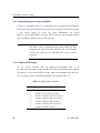
2.2 Using the DLI in the Freeway DDCMP Environment
In the Freeway system, the client addresses Freeway sessions through the DLI. All DLI
requests in the DDCMP client application must use the DLI Raw operation, which is
discussed in detail in the Freeway Data Link Interface Reference Guide.
28
DC 900-1343D
2: DDCMP DLI Functions
2.2.1 Initializing the DLI
The client application calls dlInit to initialize its interface to Freeway. This call specifies
a DLI binary configuration file, which is generated off-line from a text file (see
Appendix B for details of the configuration process). The text file contains definitions
of the sessions that can be opened, as described in the following Section 2.2.2.
Since Raw operation does not perform automatic link configuration, no protocol-specific link configuration parameters are specified in the DDCMP DLI configuration file.
2.2.2 DDCMP DLI Session Configuration
The DLI text configuration file consists of the following sections:
•
A “main” section which specifies the DLI configuration for non-session-specific
operations.
•
One or more additional sections, each specifying a protocol-specific session associated with a particular Freeway serial communication link (port). Each link can
be configured independently of the other links.
The session parameters are described in the Freeway Data Link Interface Reference
Guide. Each session has an associated TSI connection name (the transport parameter
in Figure 2–1) which you also must specify in your TSI configuration file, though multiple sessions can use the same TSI connection.
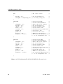
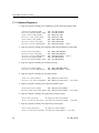
For a Freeway server, Figure 2–1 is an example DLI configuration file showing the
“main” section and two DDCMP sessions. You need to include only those session
parameters whose values differ from the defaults.
For DDCMP sessions, the required configurations which differ from the defaults are:
•
•
alwaysQIO = “yes”
• asyncIO = “yes”
cfgLink = “no”
• enable = “no”
•
localAck = “no”
• protocol = “raw”
DC 900-1343D
29
DDCMP Programmer’s Guide
main
// DLI “main” section:
{
asyncIO = “yes”;
// Use non-blocking I/O
tsiCfgName = “ddcmpaltcfg.bin”; // TSI binary config file
}
ICP0link0
{
alwaysQIO = “yes”;
asyncIO = “yes”;
cfglink = “no”;
enable = “no”;
localAck = “no”;
boardNo = 0;
portNo = 0;
protocol = “raw”;
transport = “client1”;
//
//
//
//
//
//
//
//
//
//
//
//
//
//
//
First session name:
Client-related parameters:
Queue I/Os even if complete
Use non-blocking I/O
Client configures links
Client enables links
Client processes transmit ack
First ICP is zero
First ICP link is zero
DDCMP uses raw operation
TSI connection name specified
in TSI configuration file
//
//
//
//
//
//
//
//
//
//
//
//
//
//
//
//
//
//
//
//
//
//
//
//
Second session name:
Client-related parameters:
Queue I/Os even if complete
Use non-blocking I/O
Client configures links
Client enables links
Client processes transmit ack
First ICP is zero
Second ICP link is one
DDCMP uses raw operation
TSI connection name specified
in TSI configuration file
//
//
//
//
//
//
//
//
//
//
//
//
}
ICP0link1
{
alwaysQIO = “yes”;
asyncIO = “yes”;
cfglink = “no”;
enable = “no”;
localAck = “no”;
boardNo = 0;
portNo = 1;
protocol = “raw”;
transport = “client1”;
}
Figure 2–1: DLI Configuration File for Two DDCMP Links (Freeway Server)
30
DC 900-1343D
2: DDCMP DLI Functions
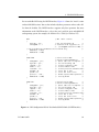
For an embedded ICP using the DLITE interface, Figure 2–2 shows the “main” section
and two DDCMP sessions. You need to include only those parameters whose values differ from the defaults. The DLITE interface supports only Raw operation. For more
information on the DLITE interface, refer to the user’s guide for your embedded ICP
and operating system (for example, the ICP2432 User’s Guide for Windows NT).
2/16/99 Per
Vic
Dobrawa:
To avoid
potential
confusion,
deleted
“transport”
parameter
(not used).
main
{
asyncIO = “yes”;
tsiCfgName = "."
// DLI “main” section:
ICP0link0
{
alwaysQIO = “yes”;
asyncIO = “yes”;
cfgLink = “no”;
enable = “no”;
localAck = “no”;
boardNo = 0;
portNo = 0;
protocol = “raw”;
maxBufSize = 1200;
}
// First session name:
//
// Client-related parameters:
//
// Queue I/Os even if complete //
// Use non-blocking I/O
//
// Client configures links
//
// Client enables links
//
// Client processes transmit ack//
// First ICP is zero
//
// First ICP link is zero
//
// DLITE requires Raw operation //
// Used by DLITE
//
ICP0link1
{
alwaysQIO = “yes”;
asyncIO = “yes”;
cfgLink = “no”;
enable = “no”;
localAck = “no”;
boardNo = 0;
portNo = 1;
protocol = “raw”;
maxBufSize = 1200;
}
// Second session name:
//
// Client-related parameters:
//
// Queue I/Os even if complete //
// Use non-blocking I/O
//
// Client configures links
//
// Client enables links
//
// Client processes transmit ack//
// First ICP is zero
//
// First ICP link is zero
//
// DLITE requires Raw operation //
// Used by DLITE
//
// Use non-blocking I/O
// Location of NT log/trace svc
//
(tsiCfgName unused for VMS)
// The following two parameters are for DLITE only:
maxBuffers = 1024;
maxBufSize = 1200;
}
//
//
//
//
//
Figure 2–2: DLI Configuration File for Two Embedded ICP Links (DLITE Interface)
DC 900-1343D
31
DDCMP Programmer’s Guide
2.2.3 Opening and Attaching DLI Sessions
After DLI initialization, the client calls dlOpen to open each DLI session. The DDCMP
protocol allows only one session per ICP link.
Using Raw operation, the client’s dlOpen call to open a session allows only the client DLI
and Freeway to handle that session. A separate step is required to allow the ICP to handle the session and to associate a link with the session. To accomplish this, the client
sends a DLI Attach command for a link in the first dlWrite issued to the session. This
informs the ICP’s Freeway interface of the session and its associated link, and then
returns the ICP session ID to be used to communicate with that session. After a session
is opened and attached, the ICP’s Freeway interface needs both the ICP session ID and
link number to route the message to the intended link and to send responses associated
with that link to the client.
When using Raw operation, the client application must use the DLI optional arguments
data structure to issue dlWrite commands to a session. The optional arguments structure is also supplied to the client by completed dlRead requests. Section 2.4.1 on page 37
describes the optional arguments.
2.2.4 Detaching and Closing DLI Sessions
To close a session, the client application first must detach it from the ICP. To accomplish
this, the client sends a DLI Detach command using a dlWrite issued to the session. This
informs the ICP’s Freeway interface that the client is ending the session. When the ICP’s
Detach response is received in the final dlRead for the session, the client calls dlClose to
end the session within the DLI and Freeway.
2.2.5 Error Reporting
Refer to Appendix A for DDCMP error reporting.
32
DC 900-1343D
2: DDCMP DLI Functions
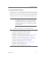
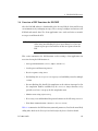
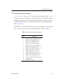
2.3 Example DDCMP Call Sequences
Table 2–2 shows the sequence of DLI function calls to send and receive data using
blocking I/O. Table 2–3 is the non-blocking I/O example. The remainder of this chapter
and the Freeway Data Link Interface Reference Guide give further information about
each function call. Section 2.1.3 on page 27 describes blocking and non-blocking I/O.
Note
The example call sequences assume that the cfgLink and enable
DLI configuration parameters are set to “no” (the default is “yes”
for both). This is necessary for the client application to configure
and enable the ICP links. Figure 2–1 on page 30 shows an example
DLI configuration file.
Table 2–2: DLI Call Sequence for DDCMP (Blocking I/O)
1. Call dlInit to initialize the DLI operating environment.
The first parameter is your DLI binary configuration file name.
2. Call dlOpen for each required session (link) to get a session ID.
3. Call dlBufAlloc for all required input and output buffers.
4. Call dlWrite to attach each session from Step 2 to the ICP (Section 2.2.3 on page 32).
5. Call dlWrite to configure and enable the ICP links (page 41 and page 42).
6. Call dlWrite to send requests and data to Freeway (Section 2.5 on page 40).
7. Call dlRead to receive responses and data from Freeway (Section 2.6 on page 48).
8. Repeat Step 6 and Step 7 until you are finished writing and reading.
9. Call dlWrite to disable the ICP links (Section 2.5.1.4 on page 43).
10. Call dlWrite to detach each session from Step 4 (Section 2.2.4 on page 32).
11. Call dlBufFree for all buffers allocated in Step 3.
12. Call dlClose for each session ID obtained in Step 2.
13. Call dlTerm to terminate your application’s access to Freeway.
DC 900-1343D
33
DDCMP Programmer’s Guide
Caution
When using non-blocking I/O, a dlRead request must always be
queued to avoid loss of data or responses from the ICP (see Step 5
of Table 2–3).
Table 2–3: DLI Call Sequence for DDCMP (Non-blocking I/O)
1. Call dlInit to initialize the DLI operating environment.
The first parameter is your DLI binary configuration file name.
2. Call dlOpen for each required session (link) to get a session ID.
3. Call dlPoll to confirm the success of each session ID obtained in Step 2.
4. Call dlBufAlloc for all required input and output buffers.
5. Call dlRead to queue the initial read request.
6. Call dlWritea to attach each session from Step 2 to the ICP (Section 2.2.3 on page 32).
7. Call dlWritea to configure and enable the ICP links (page 41 and page 42).
8. Call dlWrite to send requests and data to Freeway (Section 2.5 on page 40).
9. Call dlRead to receive responses and data from Freeway (Section 2.6 on page 48).
10. As I/Os complete and the I/O completion handler is invoked, call dlPoll to confirm the
success of each dlWrite in Step 8 and to accept the data from each dlRead in Step 9.
11. Repeat Step 8 through Step 10 until you are finished writing and reading.
12. Call dlWritea to disable the ICP links (Section 2.5.1.4 on page 43).
13. Call dlWritea to detach each session from Step 6 (Section 2.2.4 on page 32).
14. Call dlBufFree for all buffers allocated in Step 4.
15. Call dlClose for each session ID obtained in Step 2.
16. Call dlPoll to confirm that each session was closed in Step 15.
17. Call dlTerm to terminate your application’s access to Freeway.
a After each dlWrite call, wait for the proper response to arrive using calls to dlRead/dlPoll before
continuing (see Step 10).
34
DC 900-1343D
2: DDCMP DLI Functions
2.4 Overview of DLI Functions for DDCMP
After the DDCMP software is downloaded to the Freeway ICP, the client and Freeway
can communicate by exchanging messages. These messages configure and activate each
ICP link and transfer data. The client application issues reads and writes to transfer
messages to and from the ICP.
Caution
When using non-blocking I/O, there must always be at least one
dlRead request queued to avoid loss of data or responses from the
ICP.
This section summarizes the DLI functions used in writing a client application. An
overview of using the DLI functions is:
•
Start up communications (dlInit, dlOpen, dlBufAlloc)
•
Send requests and data using dlWrite
•
Receive responses using dlRea
•
For blocking I/O, use dlSyncSelect to query read availability status for multiple
sessions
•
For non-blocking I/O, handle I/O completions at the software interrupt level in
the completion handler established by the dlInit or dlOpen function, or by
periodic use of dlPoll to query the I/O completion status
•
Monitor errors using dlpErrString
•
If necessary, reset and download the protocol software to the ICP using dlControl
•
Shut down communications (dlBufFree, dlClose, dlTerm)
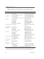
Table 2–4 summarizes the DLI function syntax and parameters, listed in the most likely
calling order. Refer to the Freeway Data Link Interface Reference Guide for details.
DC 900-1343D
35
DDCMP Programmer’s Guide
Table 2–4: DLI Functions: Syntax and Parameters (Listed in Typical Call Order)
DLI Function
Parameter(s)
Parameter Usage
int dlInit
(char *cfgFile,
char *pUsrCb,
int (*fUsrIOCH)(char *pUsrCb));
int dlOpena
(char *cSessionName,
Session name in DLI config file
int (*fUsrIOCH)
Optional I/O completion handler
(char *pUsrCB, int iSessionID)); Parameters for IOCH
int dlPoll
(int iSessionID,
int iPollType,
char **ppBuf,
int *piBufLen,
char *pStat,
DLI_OPT_ARGS **ppOptArgs);
int dlpErrString (int dlErrNo);
DLI binary configuration file name
Optional I/O complete control block
Optional IOCH and parameter
Session ID from dlOpen
Request type
Poll type dependent buffer
Size of I/O buffer (bytes)
Status or configuration buffer
Optional arguments
DLI error number (global variable
dlerrno)
char *dlBufAlloc (int iBufLen);
Minimum buffer size
int dlRead
(int iSessionID,
char **ppBuf,
int iBufLen,
DLI_OPT_ARGS *pOptArgs);
Session ID from dlOpen
Buffer to receive data
Maximum bytes to be returned
Optional arguments structure
int dlWrite
(int iSessionID,
char *pBuf,
int iBufLen,
int iWritePriority,
DLI_OPT_ARGS *pOptArgs);
Session ID from dlOpen
Source buffer for write
Number of bytes to write
Write priority (normal or expedite)
Optional arguments structure
int dlSyncSelect (int iNbrSessID,
int sessIDArray[],
int readStatArray[]);
Number of session IDs
Packed array of session IDs
Array containing read status for IDs
char *dlBufFree
(char *pBuf);
Buffer to return to pool
int dlClose
(int iSessionID,
int iCloseMode);
Session ID from dlOpen
Mode (normal or force)
int dlTerm
(void);
int dlControl
(char *cSessionName,
int iCommand,
int (*fUsrIOCH)
(char *pUsrCB, int iSessionID));
Session name in DLI config file
Command (e.g. reset/download)
Optional I/O completion handler
Parameters for IOCH
a It is critical for the client application to receive the dlOpen completion status before making any
other DLI requests; otherwise, subsequent requests will fail. After the dlOpen completion, however, you
do not have to maintain a one-to-one correspondence between DLI requests and dlRead requests.
36
DC 900-1343D
2: DDCMP DLI Functions
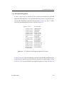
2.4.1 DLI Optional Arguments
Section 2.5 and Section 2.6 describe the dlWrite and dlRead functions for a DDCMP
application. Both functions use the optional arguments parameter to provide the protocol-specific information required for Raw operation (Section 2.1.2). The “C” definition of the optional arguments structure is shown in Figure 2–3.
typedef struct
{
unsigned short
unsigned short
unsigned short
unsigned short
unsigned short
unsigned short
short
unsigned short
unsigned short
short
unsigned short
unsigned short
unsigned short
unsigned short
unsigned short
} DLI_OPT_ARGS;
_DLI_OPT_ARGS
usFWPacketType;
usFWCommand;
usFWStatus;
usICPClientID;
usICPServerID;
usICPCommand;
iICPStatus;
usICPParms[3];
usProtCommand;
iProtModifier;
usProtLinkID;
usProtCircuitID;
usProtSessionID;
usProtSequence;
usProtXParms[2];
Figure 2–3: “C” Definition of DLI Optional Arguments Structure
Section 2.2 on page 28 described how to use the DLI in the DDCMP environment. The
required dlWrite optional arguments fields for a DDCMP client application are shown
in Table 2–5. The relevant DDCMP dlRead optional arguments are shown in Table 2–6.
DC 900-1343D
37
DDCMP Programmer’s Guide
Table 2–5: Required dlWrite Optional Arguments Fields
dlWrite Optional
Arguments Field
Value
Usage
usFWPacketType
FW_DATA
usFWCommand
FW_ICP_WRITE
usICPCommand
DLI_ICP_CMD_ATTACH
DLI_ICP_CMD_WRITE
DLI_ICP_CMD_DETACH
DLI_ICP_CMD_BIND
DLI_ICP_CMD_UNBIND
Send an Attach request for a session
Write a message buffer to a session
Send a Detach request for a session
Send a Start Link command
Send a Stop Link command
usProtCommand
See Table 2–7 on page 40
Send protocol-related commands and
requests to the ICP
iProtModifier
0 = Drop DTR modem control signal Stop Link command with DTR modem
Otherwise, DTR modem control sig- control (Section 2.5.1.4 on page 43)
nal is not dropped
usProtLinkID
Attach and Write: ICP link number for Attach request (Section 2.2.3 on page 32)
session.
Write request (Section 2.5 on page 40)
Detach: unused
usProtSessionID Attach: (unused)
Write and Detach: ICP session ID
38
Used for most DLI requests.
Detach request (Section 2.2.4 on page 32)
Write requests (Section 2.5 on page 40)
DC 900-1343D
2: DDCMP DLI Functions
Table 2–6: Relevant dlRead Optional Arguments Fields
dlRead Optional
Arguments Field
Value
Usage
usFWPacketType
FW_DATA
usFWCommand
FW_ICP_READ
usICPCommand
DLI_ICP_CMD_ATTACH
DLI_ICP_CMD_READ
DLI_ICP_CMD_DETACH
DLI_ICP_CMD_BIND
DLI_ICP_CMD_UNBIND
ICP acknowledgment of an Attach
Message buffer from a session
ICP acknowledgment of a Detach
ICP Acknowledgment of Start Link
ICP Acknowledgment of Stop Link
iICPStatus
See Appendix A
Used for error reporting
usProtCommand
See Table 2–11 on page 48
Receive protocol-related
responses from the ICP
usProtLinkID
Session link number
iProtModifier
See Table 2–12 on page 49 and
Table 2–13 on page 51
Used to identify type of incoming data or circuit exception
usProtSessionID
Attach: ICP session ID
Read and Detach: (unused)
Attach request (Section 2.2.3 on page 32)
usProtSequence
Number of messages acknowl- Final Acknowledge of Data Transmitted
edged
(Section 2.6.1.2 on page 49)
DC 900-1343D
Used for most DLI requests
reports
and
39
DDCMP Programmer’s Guide
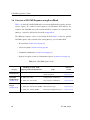
2.5 Overview of DDCMP Requests using Raw dlWrite
For DDCMP the dlWrite function supports three dlWrite categories: commands,
report requests, and data transfer, which are discussed in detail in Section 2.5.1 through
Section 2.5.3. Whether you use blocking or non-blocking I/O, each dlWrite request
must be followed by a dlRead request to receive the command confirmation, the report
requested, or the acknowledgment of the data transfer. Section 2.6 discusses these different responses received using dlRead.
In a DDCMP application, the dlWrite requests must use Raw operation; that is, the
optional arguments structure (page 37) is required to specify protocol-specific information.
Table 2–7 shows the DDCMP DLI request codes for different categories of the dlWrite
function. Each request is explained in the following sections. An unsuccessful dlWrite
request can return one of the following error codes in the dlRead pOptArgs.iICPStatus
field (see Appendix A for error handling):
DLI_ICP_ERR_INBUF_OVERFLOW
Input buffer overflow
DLI_ICP_ERR_OUTBUF_OVERFLOW Output buffer overflow
Table 2–7: Categories for DDCMP dlWrite Requests
Category
Commands
to ICP
Report Requests
Data Transfer
40
DLI Request Code in the
pOptArgs.usProtCommand Field
Usage
Reference
Section
DLI_PROT_CFG_LINK
Configure link
Section 2.5.1.1
DLI_PROT_CLR_STATISTICS
Clear statistics
Section 2.5.1.2
DLI_PROT_SEND_BIND
Start link
Section 2.5.1.3
DLI_PROT_SEND_UNBIND
Stop link
Section 2.5.1.4
DLI_PROT_GET_BUF_REPORT
Request buffer report
Section 2.5.2.1
DLI_PROT_GET_STATISTICS_REPORT
Request statistics report
Section 2.5.2.2
DLI_PROT_GET_STATUS_REPORT
Request status report
Section 2.5.2.3
DLI_PROT_SEND_NORM_DATA
Transmit normal data
Section 2.5.3.1
DC 900-1343D
2: DDCMP DLI Functions
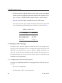
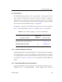
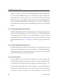
2.5.1 Commands using Raw dlWrite
Section 2.5.1.2 through Section 2.5.1.4 explain how to issue specific commands to the
DDCMP software using the dlWrite function. Call dlRead to receive the command confirmation response (the dlRead pOptArgs.usProtCommand field is set by the DLI).
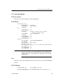
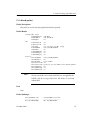
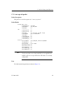
2.5.1.1 Configure Link Command
Caution
In order for the client application to perform link configuration,
both the cfgLink and enable DLI configuration parameters must
be set to “no” for each link (see Figure 2–1 on page 30).
Use the dlWrite function with the pOptArgs.usProtCommand field set to
DLI_PROT_CFG_LINK to set the link configuration options. The buffer pointed to by the
pBuf parameter contains 16 empty bytes followed by the CONFIG_TYPE data structure
shown in Figure 2–4. The dlWrite iBufLen parameter equals the size of the CONFIG_TYPE
data structure (in bytes) + 16.
/* 16 empty bytes are required immediately preceding CONFIG_TYPE.
/* These are reserved for DDCMP use.
struct CONFIG_TYPE
{
bit16 baud_rate;
/* Baud rate
bit16 clock_source;
/* Clock source
bit16 reply_tmr_sec;
/* Timer (seconds)
bit16 line_mode;
/* Synchronous/Asynchronous mode
bit16 duplex;
/* Not used (DDCMP is full duplex)
bit16 half_duplex;
/* Not used
bit16 version;
/* Baud rate
bit16 eia;
/* Electrical interface (Freeway 1000)
bit16 maint_state;
/* Maintenance mode state
};
*/
*/
*/
*/
*/
*/
*/
*/
*/
*/
*/
Figure 2–4: Configure Link Command CONFIG_TYPE Data Structure
DC 900-1343D
41
DDCMP Programmer’s Guide
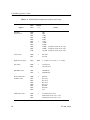
Table 3–1 on page 56 lists the available link configuration options and values for the
DDCMP protocol. The link status report (Section 2.5.2.3 on page 46) gives the current
settings for a link’s configuration options.
2.5.1.2 Clear Link Statistics Command
Use the dlWrite function with the pOptArgs.usProtCommand field set to
DLI_PROT_CLR_STATISTICS to clear the link statistics report. The link statistics are
cleared as soon as this command is received. The statistics are automatically cleared
when a Start Link command (Section 2.5.1.3) is issued.
A dlRead link statistics report response (the pOptArgs.usProtCommand field is set to
DLI_PROT_CLR_STATISTICS by the DLI) is automatically returned to the client, contain-
ing the link statistics prior to clearing. The format is shown in Section 2.5.2.2 on
page 45.
2.5.1.3 Start Link Command
Use the dlWrite function with the pOptArgs.usProtCommand field set to
DLI_PROT_SEND_BIND and the pOptArgs.usICPCommand field set to DLI_ICP_CMD_BIND to
start a link. After receiving this command, the DDCMP software turns on the DTR
modem control signal and prepares the link to transmit and receive data according to
the current link configuration settings. After a link starts, data transmission can begin
on the line.
The
first
dlRead
response
(the
pOptArgs.usProtCommand
field
is
set
to
DLI_PROT_SEND_BIND by the DLI) is sent to the client to acknowledge ICP receipt of the
Start Link command. However, the link is not considered started until the client
receives the dlRead final acknowledgment response (the pOptArgs.usProtCommand field
is set to DLI_PROT_RECV_DATA by and the pOptArgs.iProtModifier field is set to “Final
Acknowledge of Start Link” as described in Section 2.6.1.3 on page 50).
42
DC 900-1343D
2: DDCMP DLI Functions
2.5.1.4 Stop Link Command
Use the dlWrite function with the pOptArgs.usProtCommand field set to
DLI_PROT_SEND_UNBIND
and
the
pOptArgs.usICPCommand
field
set
to
DLI_ICP_CMD_UNBIND to stop a link without ending your session with Freeway. This
command shuts down the link transmitter and receiver. A Stop Link command can be
sent to a link that is active or already inactive. If the pOptArgs.iProtModifier field is set
to zero (0), then a Stop Link command causes the DTR modem control signal to be
dropped. Otherwise, the DTR modem signal is not dropped.
A dlRead response (the pOptArgs.usProtCommand field is set to DLI_PROT_SEND_UNBIND
by the DLI) is sent to the client to acknowledge ICP receipt of the Stop Link command.
The pOptArgs.iProtModifier field is set to “Final Acknowledge of Stop Link” as
described in Section 2.6.1.4 on page 50.
A call to dlClose (described in the Freeway Data Link Interface Reference Guide) also
stops the link, but terminates the session as well. This is the normal method to terminate a session at the end of a client application. The Stop Link command is useful for
temporarily stopping the link without terminating the session (for example, to reconfigure the link using the Configure Link command). The link is restarted by issuing a
Start Link command.
DC 900-1343D
43
DDCMP Programmer’s Guide
2.5.2 Information Requests using Raw dlWrite
Section 2.5.2.1 through Section 2.5.2.3 explain how to issue protocol-specific information requests to the DDCMP software using the dlWrite function. You must then make
a
Raw
request
dlRead
to
receive
the
report
information
(the
dlRead
pOptArgs.usProtCommand field is set by the DLI to reflect the type of report, and the
iBufLen parameter indicates the size of the message).
Caution
The dlWrite iBufLen parameter must specify a buffer size large
enough for the requested report; otherwise, the dlRead function
truncates the text to the size indicated by the dlWrite iBufLen
parameter.
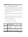
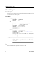
2.5.2.1 Request Buffer Report
Use the dlWrite function with the pOptArgs.usProtCommand field set to
DLI_PROT_GET_BUF_REPORT to request a buffer report. The dlRead buffer report response
(the pOptArgs.usProtCommand field is set to DLI_PROT_GET_BUF_REPORT by the DLI) consists of 7 words (14 bytes) of buffer information as described in Table 2–8.
Table 2–8: Buffer Report Definition
Word
44
Description
1
ICP message buffer size
2
Number of free ICP message buffers
3
Number of buffers in general client queue
4
Number of buffers in client input queue
5
Number of buffers in link input queue
6
Number of buffers in link output queue
7
Number of buffers in fak queue
DC 900-1343D
2: DDCMP DLI Functions
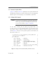
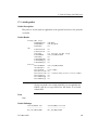
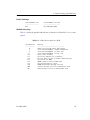
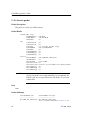
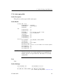
2.5.2.2 Request Link Statistics Report
Use the dlWrite function with the pOptArgs.usProtCommand field set to
DLI_PROT_GET_STATISTICS_REPORT to request link statistics. The DDCMP software
maintains a set of link statistics. The report consists of 16 words (32 bytes) of statistics.
The link statistics report is also sent to the client in response to a Clear Statistics command (Section 2.5.1.2).
The format of the dlRead link statistics report response (the pOptArgs.usProtCommand
field is set to DLI_PROT_GET_STATISTICS_REPORT by the DLI) is shown in Table 2–9.
Table 2–9: Link Statistics Report Definition
Word
1
2
3
4
5
6
7
8
9
10
11
12
13
14
15
16
DC 900-1343D
Statistic
NAKs received for header BCC errors
NAKs received for buffer BCC errors
NAKs sent for header BCC errors
NAKs sent for buffer BCC errors
NAKs sent for no buffer available
NAKs received for no buffer available
REPs sent (local reply timeouts)
REPs received (remote reply timeouts)
NAKs sent for receive overruns
NAKs received for receive overruns
NAKs sent for message too long
NAKs received for message too long
NAKs sent for header format error
NAKs received for header format error
Data blocks sent
Data blocks received
45
DDCMP Programmer’s Guide
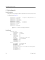
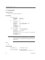
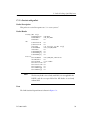
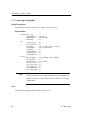
2.5.2.3 Request Link Status Report
Use the dlWrite function with the pOptArgs.usProtCommand field set to
DLI_PROT_GET_STATUS_REPORT to request the current link status and configuration
option settings. The link configuration options are changed using the Configure Link
command (Section 2.5.1.1). The
dlRead
link status report response (the
pOptArgs.usProtCommand field is set to DLI_PROT_GET_STATUS_REPORT by the DLI) con-
sists of 12 words (24 bytes) containing the information shown in Table 2–10.
Table 2–10: Link Status Report Definition
Word
46
Description
1
2
3
4
5
6
7
Link active flag
Remote status
Baud rate
Clock source
Reply timer length (seconds)
Controller state
Number of leading sync characters
8
9
10
11
12
13
Synchronous/asynchronous communications
Full/half duplex
Half-duplex status
Link is receive only
Electrical interface (Freeway 1000 only)
Maintenance state
Value
0 = inactive; 1 = active
0 = inactive; 1 = active
See Table 3–1 on page 56
See Table 3–1 on page 56
See Table 3–1 on page 56
Unused
Always = 8 (synchronous line mode)
Always = 0 (asynchronous line mode)
See Table 3–1 on page 56
Unused (DDCMP is full duplex)
Unused
Unused
See Table 3–1 on page 56
See Table 3–1 on page 56
DC 900-1343D
2: DDCMP DLI Functions
2.5.3 Data Transfer using Raw dlWrite
For the DDCMP software to properly handle data transfer, the localAck DLI configuration parameter must be set to “no” (see Figure 2–1 on page 30). After sending a data
transfer request, the client application must make a dlRead request to receive the
acknowledgment response associated with each dlWrite data transfer request, as
explained below.
2.5.3.1 Send Normal Data
Use the dlWrite function with the pOptArgs.usProtCommand field set to
DLI_PROT_SEND_NORM_DATA to send normal data. The buffer pointed to by the pBuf
parameter contains 16 empty bytes followed by the data to transmitted. The dlWrite
iBufLen parameter equals the size of the data (in bytes) + 16. The maximum iBufLen is
1000 bytes.
The data is not considered successfully transmitted and acknowledged by the remote
computer until the client receives the dlRead final acknowledgment response (the
pOptArgs.iProtModifier field is set to “Final Acknowledge of Data Transmitted” as
described in Section 2.6.1.2 on page 49).
DC 900-1343D
47
DDCMP Programmer’s Guide
2.6 Overview of DDCMP Responses using Raw dlRead
Table 2–11 shows the valid DDCMP codes sent to your application in response to a Raw
dlRead request; the returned dlRead pOptArgs.usProtCommand field indicates the
response code. DDCMP error codes associated with the responses are returned in the
pOptArgs.iICPStatus field and are described in Appendix A.
The following responses can be received from the ICP. Table 2–11 lists the possible
DDCMP response codes returned in the dlRead pOptArgs.usProtCommand field.
•
Received data (Section 2.6.1 on page 49)
•
Circuit exceptions (Section 2.6.2 on page 50)
•
Command confirmations (Section 2.6.3 on page 53)
•
Reports in response to dlWrite information requests (Section 2.6.4 on page 53)
Table 2–11: DDCMP Response Codes
Category
Incoming Data
Command
Confirmations
(Section 2.6.3)
Reports
(Section 2.6.4)
a All of
48
DLI Response Codea in the
pOptArgs.usProtCommand Field
Reference
Section
Usage
DLI_PROT_RECV_DATA
Received data
Circuit exceptions
Section 2.6.1
Section 2.6.2
DLI_PROT_CFG_LINK
Configure link confirmation
Section 2.5.1.1
DLI_PROT_CLR_STATISTICS
Clear statistics confirmation
Section 2.5.1.2
DLI_PROT_GET_BUF_REPORT
Buffer report
Section 2.5.2.1
DLI_PROT_GET_STATISTICS_REPORT Link statistics report
Section 2.5.2.2
DLI_PROT_GET_STATUS_REPORT
Section 2.5.2.3
Link status/configuration report
the responses can return an error code in the dlRead pOptArgs.iICPStatus field.
DC 900-1343D
2: DDCMP DLI Functions
2.6.1 Received Data
The DDCMP software provides the DLI_PROT_RECV_DATA dlRead response code for
data reception. The buffer pointed to by the pBuf parameter contains 16 empty bytes
followed by the received data. The dlRead iBufLen parameter equals the size of the data
(in bytes) + 16. The dlRead function returns a non-zero pOptArgs.iICPStatus field if
there is an error associated with the message (see Appendix A).
The pOptArgs.iProtModifier field defines the type of message received as shown in
Table 2–12 (for incoming data). Section 2.6.1.1 through Section 2.6.1.4 give details.
Table 2–12: Received Data: pOptArgs.iProtModifier Field Values
Value of Field
pOptArgs.
iProtModifier
Reference Section
Normal or Maintenance Data
0
Section 2.6.1.1
Final Acknowledge of Data Transmitted
7
Section 2.6.1.2
Final Acknowledge of Start Link
9
Section 2.6.1.3
Final Acknowledge of Stop Link
11
Section 2.6.1.4
Type of Received Data
2.6.1.1 Normal or Maintenance Data [0]
Normal or Maintenance Data is indicated by the DLI_PROT_RECV_DATA dlRead response
code with the pOptArgs.iProtModifier field set to zero. The packet data area contains
the actual line data received in a single DDCMP frame. This message type is generated
by the ICP. See Section 3.7 on page 58 to set the maintenance mode configuration
option.
2.6.1.2 Final Acknowledge of Data Transmitted [7]
The Final Acknowledge of Data Transmitted (either normal or maintenance data) is
indicated by the
DC 900-1343D
DLI_PROT_RECV_DATA
dlRead
response code with the
49
DDCMP Programmer’s Guide
pOptArgs.iProtModifier field set to 7. The Final Acknowledge of Data Transmitted tells
the client writing DDCMP messages to the serial line that the remote computer has
acknowledged one or more line data messages sent to the ICP serial line. Note that all
line data messages sent to an ICP line are processed in the order sent. The final acknowledge count field is the high-order byte of the pOptArgs.usProtSequence field and is set
to the number of line data messages being acknowledged. This message is generated by
the ICP.
2.6.1.3 Final Acknowledge of Start Link [9]
The Final Acknowledge of Start Link is indicated by the DLI_PROT_RECV_DATA dlRead
response code with the pOptArgs.iProtModifier field set to 9. The Final Acknowledge
of Start Link informs the client that a successful DDCMP start sequence has been
exchanged with the remote computer. This message is always in response to a previous
Start Link command (Section 2.5.1.3 on page 42). This message type is generated by the
ICP.
2.6.1.4 Final Acknowledge of Stop Link [11]
The Final Acknowledge of Stop Link is indicated by the DLI_PROT_RECV_DATA dlRead
response code with the pOptArgs.iProtModifier field set to 11. The Final Acknowledge
of Stop Link informs the client that the ICP has processed the client stop protocol
request. This message type is generated by the ICP.
2.6.2 Circuit Exceptions
Circuit exceptions are received with the DLI_PROT_RECV_DATA dlRead response code.
The buffer pointed to by the pBuf parameter contains 16 empty bytes followed by the
received data. The dlRead iBufLen parameter equals the size of the data (in bytes) + 16.
The dlRead function normally returns a non-zero pOptArgs.iICPStatus field if there is
an error associated with the message (see Appendix A). However, for circuit exceptions,
the pOptArgs.iICPStatus field will be zero, and the pOptArgs.iProtModifier field
50
DC 900-1343D
2: DDCMP DLI Functions
defines the type of circuit exception received as shown in Table 2–13. Section 2.6.2.2
through Section 2.6.2.10 give details.
Circuit exceptions are messages generated by the ICP in response to unexpected protocol events. For circuit exceptions, the pOptArgs.iProtModifier field values are greater
than 128 (decimal) to differentiate them from responses to client commands.
Odd-numbered circuit exceptions are non-fatal; that is, they do not automatically cause
the ICP to shut down DDCMP operations on the line. Even-numbered circuit exceptions are fatal; if any of these occur, DDCMP protocol on the specific line is halted,
requiring a Start Link command from the client before the line is restarted. See
Table 2–13 for the possible circuit exceptions.
Table 2–13: Circuit Exceptions: pOptArgs.iProtModifier Field Values
Value of Field
pOptArgs.
iProtModifier
Reference Section
Retry Limit Exceeded
129
Section 2.6.2.1
Receiving Computer not Responding
131
Section 2.6.2.2
Receive Message Lost due to Buffer Unavailability
133
Section 2.6.2.3
Carrier Restored
134
Section 2.6.2.4
Disconnect (No DCD)
135
Section 2.6.2.5
DDCMP Start Received in RUN State
136
Section 2.6.2.6
Received Message Too Large
138
Section 2.6.2.7
DDCMP Maintenance Message Received
140
Section 2.6.2.8
Control Message Received in Maintenance Mode
200
Section 2.6.2.9
Data Message Received in Maintenance Mode
201
Section 2.6.2.10
Type of Received Data (Circuit Exception)
2.6.2.1 Retry Limit Exceeded [129]
This exception is generated when the DDCMP retry limit has been exceeded.
DC 900-1343D
51
DDCMP Programmer’s Guide
2.6.2.2 Receiving Computer not Responding [131]
This exception is generated each seventh time that a reply (REP) message is sent because
no response was received from the remote computer. The REP is retried until a valid
response is received or the line is shut down.
2.6.2.3 Receive Message Lost due to Buffer Unavailability [133]
This exception is generated when the ICP must send a NAK in response to an incoming
data message because an ICP buffer was temporarily unavailable to receive the message.
Note that in this case no data is actually “lost” because the remote computer will receive
the NAK and retransmit the same data block again. The ICP accepts the data block
when an empty buffer becomes available.
2.6.2.4 Carrier Restored [134]
This exception is generated when the ICP detects a change of state in the Data Carrier
Detect (DCD) pin from off to on.
2.6.2.5 Disconnect (No DCD) [135]
This exception is generated when the ICP detects a change of state in the Data Carrier
Detect (DCD) pin from on to off.
2.6.2.6 DDCMP Start Received in RUN State [136]
This exception is generated when the ICP receives a DDCMP Start Link command and
the link is already in the RUN state. This exception causes the link to be set to the
HALTED state.
2.6.2.7 Received Message Too Large [138]
This exception signifies that a NAK was sent in response to an incoming data message
because the data size was larger than the configured ICP buffer size. This exception
causes the link to be set to the HALTED state.
52
DC 900-1343D
2: DDCMP DLI Functions
2.6.2.8 DDCMP Maintenance Message Received [140]
This exception is caused by the reception of a DDCMP maintenance message when the
link is not in maintenance mode (Section 3.7 on page 58). The message is ignored and
the link is halted.
2.6.2.9 Control Message Received in Maintenance Mode [200]
10/97 Leslie:
These last two
were
confusing, but
Fred and I
agreed to leave
them in the
category of
circuit
exceptions.
This exception indicates that a normal DDCMP control message was received while in
maintenance mode state two (maintenance mode on). The DDCMP control message
type is indicated by the high-order of the pOptArgs.usProtSequence field as follows:
1 = ACK
2 = NAK
3 = REP
6 = START
8 = STACK
2.6.2.10 Data Message Received in Maintenance Mode [201]
This exception indicates that a normal DDCMP data message was received while in
maintenance mode.
2.6.3 Confirmation Responses
Refer back to Table 2–11 on page 48 for a list of the possible DDCMP confirmation
response codes returned in the dlRead pOptArgs.usProtCommand field. All of the
responses can return an error code in the dlRead pOptArgs.iICPStatus field to indicate
failure.
2.6.4 Reports in Response to dlWrite Information Requests
After issuing a dlWrite information request (Section 2.5.2 on page 44), you must issue
a dlRead request to receive the report information. Refer back to Table 2–11 on page 48
for a list of the available reports. The report formats are shown in Section 2.5.2.1
through Section 2.5.2.3.
DC 900-1343D
53
DDCMP Programmer’s Guide
54
DC 900-1343D
Chapter
3
DDCMP Link
Configuration Options
This chapter describes the various link configuration options that can be set using the
dlWrite Configure Link command as described in Section 2.5.1.1 on page 41.
Table 3–1 lists all the available options, the allowed settings, and the defaults. The
defaults are in effect immediately after the protocol software is downloaded to the ICP.
They remain in effect until you send a dlWrite Configure Link command or redownload the protocol software to the ICP.
Note
Link configuration options can be set only when the link being
configured is stopped.
3.1 Data Rate Option
The data rate can be set by the client for installations using internal clocking, where the
communications server must generate the data clocking signal. If external clocking is
provided by a modem or modem eliminator, the configuration of the data rate is not
required. The allowable data rates depend on the setting of the Line Mode option
(Section 3.4).
The data rate on a link can be set from 300 through 38,400 bits/second (and up to
263,100 bits/second for synchronous line mode). When using data rates above 19,200
bits/second, be careful not to overload the communications server processor. Freeway
supports up to 16 links per ICP.
DC 900-1343D
55
DDCMP Programmer’s Guide
Table 3–1: DDCMP Link Configuration Options and Settings
Option
Data Rate
(bits/second)
56
Value
(hex)
0x00
0x01
0x02
0x03
0x04
0x05
0x06
0x07
0x08
0x09
0x0a
Default
(✓)
✓
Clock Source
0x00
0x01
✓
Reply Timer Length
0x0n
0x03
Line Mode
0x00
0x01
✓
DDCMP Version
0x02
0x28
✓
Setting
300
600
1,200
2,400
4,800
9,600
19,200
38,400
56,000 (Synchronous line mode only)
64,000 (Synchronous line mode only)
263,100 (Synchronous line mode only)
External
Internal
n = number of seconds (1 ≤ n ≤ 65535)
Synchronous
Asynchronous
DDCMP I2
DDCMP 4.0
Electrical Interface
(ICP2432 only)
0x00
0x01
0x02
0x03
0x04
0x05
0x06
0x07
✓
EIA-232
Reserved
Reserved
Reserved
Reserved
EIA-449
EIA-530
V.35
Maintenance State
0x00
0x01
0x02
✓
No maintenance mode
Maintenance mode state 1 (off)
Maintenance mode state 2 (on)
DC 900-1343D
3: DDCMP Link Configuration Options
3.2 Clock Source Option
The clock source option determines the source of the data clock signals for a link. Data
clocking can be provided by the DDCMP software or received from an external source.
3.2.1 External
Simpact recommends the external clock setting for most communications applications
that involve a cable length greater than 25 feet. In the external setting, the clock generator is disabled. Data clocking must be supplied by an external source such as a modem
or modem eliminator. Receive clocking is input through the receiver timing signal
(EIA-232 pin 17), and transmit clocking is input through the transmitter timing signal
(EIA-232 pin 15). The Freeway 2000/4000 server is factory configured for external
clocking using a hardware jumper.
3.2.2 Internal
When the internal clock setting is used, the clock signal is generated at the rate specified
in the data rate option (Section 3.1). The generated clock signal is used for transmit
clocking and is output on the terminal timing signal (EIA-232 pin 24). Receive clocking
is input through the receiver timing signal (EIA-232 pin 17). The transmitter timing
signal (EIA-232 pin 15) is not used. The Freeway 2000/4000 server is factory configured
for external clocking using a hardware jumper. If you need to set internal clocking on
the Freeway 2000/4000, call the Simpact customer support number given in the Preface.
3.3 Reply Timer Length Option
The reply time is the length of time in seconds that the DDCMP software waits for the
remote station to reply to a transmission. If the remote station does not respond within
the configured timeout period, the DDCMP software aborts the transmission and
sends the DLI_ICP_ERR_RETRY_EXCEEDED retry limit error to the client.
DC 900-1343D
57
DDCMP Programmer’s Guide
3.4 Line Mode Option
This option selects the mode of serial communications, either synchronous or asynchronous. This option also affects the allowed data rate values (see Table 3–1).
3.5 DDCMP Version Option
This option selects the DDCMP version, either DDCMP I2 or DDCMP 4.0.
3.6 Electrical Interface Option
The electrical interface option applies only to the ICP2432 (such as in the Freeway
1100/1150) and allows the electrical interface for each link to be set. The valid values are
EIA-232 (default), EIA-449, EIA-530, and V.35.
3.7 Maintenance Mode Option
This option allows setting of DDCMP maintenance mode to either zero (no maintenance allowed), or to specify maintenance mode state 1 (off) or maintenance mode
state 2 (on). In any of the three modes, any maintenance message received by the ICP
causes
a
DLI_PROT_RECV_DATA
dlRead
response
code
in
the
dlRead
pOptArgs.usProtCommand field (see Section 2.6.1.1 on page 49).
See Section 2.6.2.8 on page 53 through Section 2.6.2.10 on page 53 for how the ICP
handles circuit exceptions relating to maintenance mode.
58
DC 900-1343D
Appendix
A
Error Codes
There are several methods used by the DLI and DDCMP software to report errors
(Table A–1 lists the DDCMP errors). The DLI error constant definitions are in the file
dlicperr.h.
1. The error code can be returned directly by the DLI function call. Typical errors
are those described in the Freeway Data Link Interface Reference Guide.
2. The DDCMP errors listed in Table A–1 can be returned in the global variable
iICPStatus.
3. The DDCMP errors listed in Table A–1 can also be returned in the dlRead
pOptArgs.iICPStatus field of the response to a dlWrite request. The DLI sets the
dlRead pOptArgs.usProtCommand field to the same value as the dlWrite request
that caused the error. An example of this type of error is the DLI_ICP_ERR_BAD_CMD
invalid command error.
DC 900-1343D
59
DDCMP Programmer’s Guide
Table A–1: DDCMP Error Codes
Code
DLI Constant Name
Meaning
0
DLI_ICP_ERR_NO_ERR
A data block has been successfully transmitted or
received on the line or a command has been successfully executed.
–105
DLI_ICP_ERR_BAD_CMD
The command from the client program is not a legal
value.
–117
DLI_ICP_ERR_LINK_ACTIVE
The link is already started.
–122
DLI_ICP_ERR_BAD_PARMS
The parameter value(s) used for the function call are
illegal.
–127
DLI_ICP_ERR_RETRY_EXCEEDED
The retry limit was exceeded while attempting to transmit a data block or select a tributary station. The message is discarded.
–145
DLI_ICP_ERR_INBUF_OVERFLOW
Server buffer input overflow
–146
DLI_ICP_ERR_OUTBUF_OVERFLOW
Server buffer output overflow
60
DC 900-1343D
Appendix
B
Note
DLI and TSI
Configuration Process
In this document, the term “Freeway” can mean either a Freeway
server or an embedded ICP. For the embedded ICP, also refer to
the user’s guide for your ICP and operating system (for example,
the ICP2432 User’s Guide for Windows NT).
This chapter summarizes the process for configuring DLI sessions and TSI connections.
DLI and TSI text configuration files are used as input to the dlicfg and tsicfg preprocessor programs to produce binary configuration files which are used by the dlInit and
dlOpen functions. For embedded ICPs, only a DLI configuration file is used (not a TSI
configuration file).
During your client application development and testing, you might need to perform
DLI configuration repeatedly (as well as TSI configuration for a Freeway server).
Note
Some of the specifics regarding DDCMP DLI session configuration were described earlier in Section 2.2.2 on page 29.
You should be familiar with the protocol-independent configuration procedures
described in the Freeway Data Link Interface Reference Guide and the Freeway Transport
Subsystem Interface Reference Guide.
DC 900-1343D
61
DDCMP Programmer’s Guide
The DLI and TSI configuration files provided with the product are listed in Table B–1.
Table B–1: Configuration File Names
Freeway Server
Embedded ICP
DLI:
ddcmpaldcfg
ddcacfg
ddcscfg
TSI:
ddcmpaltcfg
TSI not applicable
for embedded ICP
The DLI and TSI configuration procedures are summarized as follows. Keep in mind
that TSI configuration does not apply to an embedded ICP environment.
1. For a Freeway server, create or modify a TSI text configuration file specifying the
configuration of the TSI connections (for example, ddcmpaltcfg in the
freeway/client/test/ddcmp directory).
2. Create or modify a DLI text configuration file specifying the DLI session configuration for all ICPs and serial communication links in your system (for example,
ddcmpaldcfg in the freeway/client/test/ddcmp directory).
3. If you have a UNIX or Windows NT system, skip this step. If you have a VMS system, run the makefc.com command file from the [FREEWAY.CLIENT.TEST.DDCMP]
directory to create the foreign commands used for dlicfg and tsicfg.
@MAKEFC <tcp-sys>
where <tcp-sys> is your TCP/IP package:
MULTINET
(for a Multinet system)
TCPWARE
(for TCPware system)
UCX
(for a UCX system)
VMS example: @MAKEFC UCX
4. For a Freeway server, go to the freeway/client/test/ddcmp directory and execute
tsicfg with the text file from Step 1 as input. This creates the TSI binary config-
62
DC 900-1343D
B: DLI and TSI Configuration Process
uration file in the same directory as the location of the text file (unless a different
path is supplied with the optional filename). If the optional filename is not supplied, the binary file is given the same name as your TSI text configuration file
plus a .bin extension.
tsicfg TSI-text-configuration-filename [TSI-binary-configuration-filename]
VMS example:
tsicfg ddcmpaltcfg
UNIX example: freeway/client/op-sys/bin/tsicfg ddcmpaltcfg
NT example:
freeway\client\op-sys\bin\tsicfg ddcmpaltcfg
5. From the freeway/client/test/ddcmp (or the freeway/client/nt_dlite/ddcmp)
directory, execute dlicfg with the text file from Step 2 as input. This creates the
DLI binary configuration file in the same directory as the location of the text file
(unless a different path is supplied with the optional filename). If the optional
filename is not supplied, the binary file is given the same name as your DLI text
configuration file plus a .bin extension.
dlicfg DLI-text-configuration-filename [DLI-binary-configuration-filename]
VMS example:
dlicfg ddcmpaldcfg
UNIX example:
freeway/client/op-sys/bin/dlicfg ddcmpaldcfg
NT example:
freeway\client\op-sys\bin\dlicfg ddcmpaldcfg
Note
DC 900-1343D
You must rerun dlicfg or tsicfg whenever you modify the text
configuration file so that the DLI or TSI functions can apply the
changes. On all but VMS systems, if a binary file already exists with
the same name in the directory, the existing file is renamed by
appending the .BAK extension. If the renamed file duplicates an
existing file in the directory, the existing file is removed by the configuration preprocessor program.
63
DDCMP Programmer’s Guide
6. If you have a UNIX system, move the binary configuration files that you created
in Step 4 and Step 5 into the appropriate freeway/client/op-sys/bin directory
Techpubs —
keep the opsys up-todate with
DC900-1333
where op-sys indicates the operating system: dec, hpux, sgi, solaris, or sunos.
UNIX example: mv ddcmpaldcfg.bin /usr/local/freeway/client/hpux/bin
mv ddcmpaltcfg.bin /usr/local/freeway/client/hpux/bin
7. If you have a VMS system, run the move.com command file from the
[FREEWAY.CLIENT.TEST.DDCMP] directory. This moves the binary configuration
files you created in Step 4 and Step 5 into the bin directory for your particular
TCP/IP package.
@MOVE filename <tcp-sys>
where filename is the name of the binary configuration file and
<tcp-sys> is the TCP/IP package:
MULTINET
(for a Multinet system)
TCPWARE
(for TCPware system)
UCX
(for a UCX system)
VMS example: @MOVE DDCMPALDCFG.BIN UCX
8. If you have a Windows NT system, move the binary configuration files that you
created in Step 4 and Step 5 into the appropriate freeway\client\op-sys\bin
Techpubs —
keep the opsys up-todate with
DC900-1333
directory where op-sys indicates the operating system: axp_nt or int_nt (for a
Freeway server); axp_nt_emb or int_nt_emb (for an embedded ICP).
NT example: copy ddcmpaldcfg.bin \freeway\client\axp_nt\bin
copy ddcmpaltcfg.bin \freeway\client\axp_nt\bin
When your application calls the dlInit function, the DLI and TSI binary configuration
files generated in Step 4 and Step 5 are used to configure the DLI sessions and TSI connections. Figure B–1 shows the configuration process.
64
DC 900-1343D
B: DLI and TSI Configuration Process
Application
dlicfg
DLI
DLI Text
Configuration File
DLI Configuration
Preprocessor
DLI Binary
Configuration File
TSI
(Freeway Server
Only)
2836
tsicfg
TSI Text
Configuration File
TSI Configuration
Preprocessor
TSI Binary
Configuration File
Transport
Environment
Figure B–1: DLI and TSI Configuration Process
DC 900-1343D
65
DDCMP Programmer’s Guide
66
DC 900-1343D
Appendix
C
Packet Exchange
Quick Reference
This appendix is intended for programmers writing an application program under one
of the following conditions:
1. If you are writing to Simpact’s data link interface (DLI) using Raw operation,
refer also to the Freeway Data Link Interface Reference Guide. If you are using the
embedded DLITE interface, also refer to the user’s guide for your particular ICP
and operating system; for example, the ICP2432 User’s Guide for Windows NT.
2. If you are writing a non-DLI application using a Simpact driver interface, refer
also to the user’s guide for your particular ICP and operating system; for example,
the ICP2432 User’s Guide for Windows NT.
3. If you are writing a non-DLI application using a socket interface, refer also to the
Freeway Client-Server Interface Control Document.
C.1 Application Sequence of Events
1. Establish a connection to a link (see Section C.2 below)
•
•
•
Attach to the ICP
Configure the link
Start the link
2. Send and Receive data, get reports, etc.
3. Terminate the connection
•
•
DC 900-1343D
Stop the link
Detach from the ICP
67
DDCMP Programmer’s Guide
C.2 Command Sequences
1. Sequence of packet exchanges for establishing a connection and starting a link
Send an ICP attach-packet
Recieve an attach-packet (ack)
Send a link-config-packet
Receive a link config (ack)
Send a start-link-packet
Recieve a start link (ack)
Receive a receive-data-packet
(DLI_ICP_CMD_ATTACH)
(DLI_ICP_CMD_ATTACH)
(DLI_PROT_CFG_LINK)
(DLI_PROT_CFG_LINK)
(DLI_PROT_SEND_BIND)
(DLI_PROT_SEND_BIND)
(DLI_PROT_RECV_DATA) - mod=9
2. Sequence of packet exchanges for stopping a link and terminating a connection
Send a stop-link-packet
Recieve a stop link (ack)
Receive a receive-data-packet
Send an ICP detach-packet
Recieve an detach-packet (ack)
(DLI_PROT_SEND_UNBIND)
(DLI_PROT_SEND_UNBIND)
(DLI_PROT_RECV_DATA) - mod=11
(DLI_ICP_CMD_DETACH)
(DLI_ICP_CMD_DETACH)
3. Sequence of packet exchanges for writing a message
Send a write-data-packet
Receive a receive-data-packet
(DLI_PROT_SEND_NORM_DATA)
(DLI_PROT_RECV_DATA) - mod=7
4. Sequence of packet exchanges for clearing statistics
Send a clr-stats-packet
Receive a clr-stats-ack-packet
(DLI_PROT_CLR_STATISTICS)
(DLI_PROT_CLR_STATISTICS) - with data
5. Sequence of packet exchanges for requesting a buffer report
Send a buf-report-packet
(DLI_PROT_GET_BUF_REPORT)
Receive a buf-report-ack-packet (DLI_PROT_GET_BUF_REPORT) - with data
6. Sequence of packet exchanges for requesting a statistics report
Send a stats-rpt-packet
(DLI_PROT_GET_STATISTICS_REPORT)
Receive a stats-rpt-ack-packet (DLI_PROT_GET_STATISTICS_REPORT) - with data
7. Sequence of packet exchanges for requesting a status report
Send a status-rpt-packet
(DLI_PROT_GET_STATUS_REPORT)
Receive a status-rpt-ack-packet (DLI_PROT_GET_STATUS_REPORT) - with data
68
DC 900-1343D
C: Packet Exchange Quick Reference
C.3 attach-packet
Packet Description
This packet is used to attach an application to the protocol and retrieve the protocol’s
session ID.
Packet Header
Freeway (DLI only):
usFWPacketType
usFWCommand
usFWStatus
ICP:
usICPClientID
usICPServerID
[usLength
usICPCommand
iICPStatus
usICPParams[0]
usICPParams[1]
usICPParams[2]
Protocol:
usProtCommand
iProtModifier
usProtLinkID
usProtCircuitID
usProtSessionID
usProtSequence
usProtXParms[0]
usProtXParms[1]
Note
= FW_DATA
= FW_ICP_WRITE
= 0
=
=
=
=
=
=
=
=
0
0
16 (used for non-DLI only)]
DLI_ICP_CMD_ATTACH
0
0
0
0
=
=
=
=
=
=
=
=
DLI_ICP_CMD_ATTACH
0
port number
0
0 - returned with protocol session number
0
0
0
The Freeway header is used only with DLI (it is not applicable for
DLITE), and the usLength field of the ICP header is used only
without DLI.
Data
None
Packet Exchanges
usProtCommand sent
-----------------DLI_ICP_CMD_ATTACH
DC 900-1343D
usProtCommand received
---------------------DLI_ICP_CMD_ATTACH
69
DDCMP Programmer’s Guide
C.4 link-config-packet
Packet Description
This packet is used to configure a link. The data field consists of a data structure with
the format shown in Figure C–1.
unsigned
unsigned
unsigned
unsigned
unsigned
unsigned
unsigned
unsigned
unsigned
unsigned
short
short
short
short
short
short
short
short
short
short
reserved[8];
/* 16 bytes for ddcmp internal use */
baud_rate;
clock_source;
reply_tmr_sec;
line_mode;
duplex;
/* unused */
half_duplex;
/* unused */
version;
eia;
maintstate;
Figure C–1: “C” Structure for Configure Link Packet
Packet Header
Freeway (DLI only):
usFWPacketType
usFWCommand
usFWStatus
ICP:
usICPClientID
usICPServerID
[usLength
usICPCommand
iICPStatus
usICPParams[0]
usICPParams[1]
usICPParams[2]
Protocol:
usProtCommand
iProtModifier
usProtLinkID
usProtCircuitID
usProtSessionID
usProtSequence
usProtXParms[0]
usProtXParms[1]
70
= FW_DATA
= FW_ICP_WRITE
= 0
=
=
=
=
=
=
=
=
0
0
50 (used for non-DLI only)]
DLI_ICP_CMD_WRITE
0
0
0
0
= DLI_PROT_CFG_LINK
= 0
= port number
= 0
= protocol session number from “attach-packet”
= 0
= 0
= 0
DC 900-1343D
C: Packet Exchange Quick Reference
Note
The Freeway header is used only with DLI (it is not applicable for
DLITE), and the usLength field of the ICP header is used only
without DLI.
Data
Data formatted as listed above.
Packet Exchanges
usProtCommand sent
-----------------DLI_PROT_CFG_LINK
DC 900-1343D
usProtCommand received
---------------------DLI_PROT_CFG_LINK
71
DDCMP Programmer’s Guide
C.5 start-link-packet
Packet Description
This packet is used to start or enable a link.
Packet Header
Freeway (DLI only):
usFWPacketType
usFWCommand
usFWStatus
ICP:
usICPClientID
usICPServerID
[usLength
usICPCommand
iICPStatus
usICPParams[0]
usICPParams[1]
usICPParams[2]
Protocol:
usProtCommand
iProtModifier
usProtLinkID
usProtCircuitID
usProtSessionID
usProtSequence
usProtXParms[0]
usProtXParms[1]
Note
= FW_DATA
= FW_ICP_WRITE
= 0
=
=
=
=
=
=
=
=
0
0
16 (used for non-DLI only)]
DLI_ICP_CMD_BIND
0
0
0
0
= DLI_PROT_SEND_BIND
= 0
= port number
= 0
= protocol session number from “attach-packet”
= 0
= 0
= 0
The Freeway header is used only with DLI (it is not applicable for
DLITE), and the usLength field of the ICP header is used only
without DLI.
Data
None
Packet Exchanges
usProtCommand sent
-----------------DLI_PROT_SEND_BIND
72
usProtCommand received
---------------------DLI_PROT_SEND_BIND - sometimes (bug?)
DLI_PROT_RECV_DATA with iProtModifier = 9
DC 900-1343D
C: Packet Exchange Quick Reference
C.6 write-data-packet
Packet Description
This packet is used to send data to a remote application.
Packet Header
Freeway (DLI only):
usFWPacketType
usFWCommand
usFWStatus
ICP:
usICPClientID
usICPServerID
[usLength
usICPCommand
iICPStatus
usICPParams[0]
usICPParams[1]
usICPParams[2]
Protocol:
usProtCommand
iProtModifier
usProtLinkID
usProtCircuitID
usProtSessionID
usProtSequence
usProtXParms[0]
usProtXParms[1]
Note
= FW_DATA
= FW_ICP_WRITE
= 0
= 0
= 0
= length of data & protocol header
(used for non-DLI only)]
= DLI_ICP_CMD_WRITE
= 0
= 0
= 0
= 0
= DLI_PROT_SEND_NORM_DATA
= 0
= port number
= 0
= protocol session number from “attach-packet”
= 0
= 0
= 0
The Freeway header is used only with DLI (it is not applicable for
DLITE), and the usLength field of the ICP header is used only
without DLI.
Data
Data to be sent to remote application with the first 16 bytes reserved for DDCMP protocol use.
Packet Exchanges
usProtCommand sent
-----------------DLI_PROT_SEND_NORM_DATA
DC 900-1343D
usProtCommand received
---------------------DLI_PROT_RECV_DATA with iProtModifier = 7
73
DDCMP Programmer’s Guide
C.7 receive-data-packet
Packet Description
This packet is received for data from a remote application, for acknowledgment of some
sent commands and for ICP exceptions.
Packet Header
Freeway (DLI only):
usFWPacketType
usFWCommand
usFWStatus
ICP:
usICPClientID
usICPServerID
[usLength
usICPCommand
iICPStatus
usICPParams[0]
usICPParams[1]
usICPParams[2]
Protocol:
usProtCommand
iProtModifier
usProtLinkID
usProtCircuitID
usProtSessionID
usProtSequence
usProtXParms[0]
usProtXParms[1]
Note
= FW_DATA
= FW_ICP_READ
= 0
= 0
= 0
= length of data & protocol header
(used for non-DLI only)]
= DLI_ICP_CMD_READ
= - 0 or error value
= 0
= 0
= 0
= DLI_PROT_RECV_DATA
= - 0 for data, else see Table C–1 below
= port number
= 0
= protocol session number from “attach-packet”
= 0
= 0
= 0
The Freeway header is used only with DLI (it is not applicable for
DLITE), and the usLength field of the ICP header is used only
without DLI.
Data
Data received from remote application if iProtModifier = 0
74
DC 900-1343D
C: Packet Exchange Quick Reference
Packet Exchanges
usProtCommand sent
-----------------None
usProtCommand received
---------------------DLI_PROT_RECV_DATA
Modifier Meanings
Table C–1 shows the possible values for the iProtModifier field of the “receive-datapacket”.
Table C–1: Values for iProtModifier Field
iProtModifier
------------0
7
9
11
129
131
133
135
136
138
140
200
201
DC 900-1343D
Meaning
-----------------------------------Data received from remote application
Final acknowledgement of data transmitted
Final acknowledgement of start link
Final acknowledgement of stop link
Retry limit exceeded
Receiving computer not responding
Receive data lost due to buffer unavailability
Disconnect (no DCD)
DDCMP start received in RUN state
Received message too large
DDCMP maintenance message received
Control message received in maintenance mode
Data message received in maintenance mode
75
DDCMP Programmer’s Guide
C.8 stop-link-packet
Packet Description
This packet is used to stop or disable a link.
Packet Header
Freeway (DLI only):
usFWPacketType
usFWCommand
usFWStatus
ICP:
usICPClientID
usICPServerID
[usLength
usICPCommand
iICPStatus
usICPParams[0]
usICPParams[1]
usICPParams[2]
Protocol:
usProtCommand
iProtModifier
usProtLinkID
usProtCircuitID
usProtSessionID
usProtSequence
usProtXParms[0]
usProtXParms[1]
Note
= FW_DATA
= FW_ICP_WRITE
= 0
=
=
=
=
=
=
=
=
0
0
16 (used for non-DLI only)]
DLI_ICP_CMD_UNBIND
0
0
0
0
= DLI_PROT_SEND_UNBIND
= - 0 to drop DTR, else 1
= port number
= 0
= protocol session number from “attach-packet”
= 0
= 0
= 0
The Freeway header is used only with DLI (it is not applicable for
DLITE), and the usLength field of the ICP header is used only
without DLI.
Data
None
Packet Exchanges
usProtCommand sent
-----------------DLI_PROT_SEND_UNBIND
76
usProtCommand received
---------------------DLI_PROT_SEND_UNBIND
DLI_PROT_RECV_DATA with iProtModifier = 11
DC 900-1343D
C: Packet Exchange Quick Reference
C.9 detach-packet
Packet Description
This packet is used to detach an application from the protocol.
Packet Header
Freeway (DLI only):
usFWPacketType
usFWCommand
usFWStatus
ICP:
usICPClientID
usICPServerID
[usLength
usICPCommand
iICPStatus
usICPParams[0]
usICPParams[1]
usICPParams[2]
Protocol:
usProtCommand
iProtModifier
usProtLinkID
usProtCircuitID
usProtSessionID
usProtSequence
usProtXParms[0]
usProtXParms[1]
Note
= FW_DATA
= FW_ICP_WRITE
= 0
=
=
=
=
=
=
=
=
0
0
16 (used for non-DLI only)]
DLI_ICP_CMD_DETACH
0
0
0
0
=
=
=
=
=
=
=
=
DLI_ICP_CMD_DETACH
0
port number
0
protocol session number from “attach-packet”
0
0
0
The Freeway header is used only with DLI (it is not applicable for
DLITE), and the usLength field of the ICP header is used only
without DLI.
Data
None
Packet Exchanges
usProtCommand sent
-----------------DLI_ICP_CMD_DETACH
DC 900-1343D
usProtCommand received
---------------------DLI_ICP_CMD_DETACH
77
DDCMP Programmer’s Guide
C.10 clr-stats-packet
Packet Description
This packet is used to clear a links statistics.
Packet Header
Freeway (DLI only):
usFWPacketType
usFWCommand
usFWStatus
ICP:
usICPClientID
usICPServerID
[usLength
usICPCommand
iICPStatus
usICPParams[0]
usICPParams[1]
usICPParams[2]
Protocol:
usProtCommand
iProtModifier
usProtLinkID
usProtCircuitID
usProtSessionID
usProtSequence
usProtXParms[0]
usProtXParms[1]
Note
= FW_DATA
= FW_ICP_WRITE
= 0
=
=
=
=
=
=
=
=
0
0
16 (used for non-DLI only)]
DLI_ICP_CMD_WRITE
0
0
0
0
=
=
=
=
=
=
=
=
DLI_PROT_CLR_STATISTICS
0
port number
0
protocol session number from “attach-packet”
0
0
0
The Freeway header is used only with DLI (it is not applicable for
DLITE), and the usLength field of the ICP header is used only
without DLI.
Data
None
Packet Exchanges
usProtCommand sent
-----------------DLI_PROT_CLR_STATISTICS
78
usProtCommand received
---------------------DLI_PROT_CLR_STATISTICS
(see “clr-stats-ack-packet” Section C.11)
DC 900-1343D
C: Packet Exchange Quick Reference
C.11 clr-stats-ack-packet
Packet Description
This packet is received in response to a “clr-stats-packet”.
Packet Header
Freeway (DLI only):
usFWPacketType
usFWCommand
usFWStatus
ICP:
usICPClientID
usICPServerID
[usLength
usICPCommand
iICPStatus
usICPParams[0]
usICPParams[1]
usICPParams[2]
Protocol:
usProtCommand
iProtModifier
usProtLinkID
usProtCircuitID
usProtSessionID
usProtSequence
usProtXParms[0]
usProtXParms[1]
Note
= FW_DATA
= FW_ICP_READ
= 0
=
=
=
=
=
=
=
=
0
0
48 (used for non-DLI only)]
DLI_ICP_CMD_READ
0
0
0
0
=
=
=
=
=
=
=
=
DLI_PROT_CLR_STATISTICS
0
port number
0
0
0
0
0
The Freeway header is used only with DLI (it is not applicable for
DLITE), and the usLength field of the ICP header is used only
without DLI.
Data
The Link Statistics Report format is shown in Figure C–2.
DC 900-1343D
79
DDCMP Programmer’s Guide
Word
---1
2
3
4
5
6
7
8
9
10
11
12
13
14
15
16
Statistic
--------NAKs received for header BCC errors
NAKs received for buffer BCC errors
NAKs sent for header BCC errors
NAKs sent for buffer BCC errors
NAKs sent for no buffer available
NAKs received for no buffer available
REPs sent (local reply timeouts)
Reps received (remote reply timeouts)
NAKs sent for receive overruns
NAKs received for receive overruns
NAKs sent for message too long
NAKs received for message too long
NAKs sent for header format error
NAKs received for header format error
Data blocks sent
Data blocks received
Figure C–2: Link Statistics Report Format
Packet Exchanges
usProtCommand sent
-----------------None
80
usProtCommand received
---------------------DLI_PROT_CLR_STATISTICS
DC 900-1343D
C: Packet Exchange Quick Reference
C.12 buf-report-packet
Packet Description
This packet is used to request a buffer report.
Packet Header
Freeway (DLI only):
usFWPacketType
usFWCommand
usFWStatus
ICP:
usICPClientID
usICPServerID
[usLength
usICPCommand
iICPStatus
usICPParams[0]
usICPParams[1]
usICPParams[2]
Protocol:
usProtCommand
iProtModifier
usProtLinkID
usProtCircuitID
usProtSessionID
usProtSequence
usProtXParms[0]
usProtXParms[1]
Note
= FW_DATA
= FW_ICP_WRITE
= 0
=
=
=
=
=
=
=
=
0
0
16 (used for non-DLI only)]
DLI_ICP_CMD_WRITE
0
0
0
0
=
=
=
=
=
=
=
=
DLI_PROT_GET_BUF_REPORT
0
port number
0
protocol session number from “attach-packet”
0
0
0
The Freeway header is used only with DLI (it is not applicable for
DLITE), and the usLength field of the ICP header is used only
without DLI.
Data
None
Packet Exchanges
usProtCommand sent
-----------------DLI_PROT_GET_BUF_REPORT
DC 900-1343D
usProtCommand received
---------------------DLI_PROT_GET_BUF_REPORT
(see “buf-report-ack-packet” Section C.13)
81
DDCMP Programmer’s Guide
C.13 buf-report-ack-packet
Packet Description
This packet is received in response to a “buf-report-packet”.
Packet Header
Freeway (DLI only):
usFWPacketType
usFWCommand
usFWStatus
ICP:
usICPClientID
usICPServerID
[usLength
usICPCommand
iICPStatus
usICPParams[0]
usICPParams[1]
usICPParams[2]
Protocol:
usProtCommand
iProtModifier
usProtLinkID
usProtCircuitID
usProtSessionID
usProtSequence
usProtXParms[0]
usProtXParms[1]
Note
= FW_DATA
= FW_ICP_READ
= 0
=
=
=
=
=
=
=
=
0
0
30 (used for non-DLI only)]
DLI_ICP_CMD_READ
0
0
0
0
=
=
=
=
=
=
=
=
DLI_PROT_GET_BUF_REPORT
0
port number
0
0
0
0
0
The Freeway header is used only with DLI (it is not applicable for
DLITE), and the usLength field of the ICP header is used only
without DLI.
Data
The Buffer Report format is shown in Figure C–3.
82
DC 900-1343D
C: Packet Exchange Quick Reference
Word
---1
2
3
4
5
6
7
Description
----------ICP message buffer size
Number of free ICP message buffers
Number of buffers in general client queue
Number of buffers in client input queue
Number of buffers in link input queue
Number of buffers in link output queue
Number of buffers in in fak queue
Figure C–3: Buffer Report Format
Packet Exchanges
usProtCommand sent
-----------------None
DC 900-1343D
usProtCommand received
---------------------DLI_PROT_GET_BUF_REPORT
83
DDCMP Programmer’s Guide
C.14 stats-rpt-packet
Packet Description
This packet is used to request a links statistics report.
Packet Header
Freeway (DLI only):
usFWPacketType
usFWCommand
usFWStatus
ICP:
usICPClientID
usICPServerID
[usLength
usICPCommand
iICPStatus
usICPParams[0]
usICPParams[1]
usICPParams[2]
Protocol:
usProtCommand
iProtModifier
usProtLinkID
usProtCircuitID
usProtSessionID
usProtSequence
usProtXParms[0]
usProtXParms[1]
Note
= FW_DATA
= FW_ICP_WRITE
= 0
=
=
=
=
=
=
=
=
0
0
16 (used for non-DLI only)]
DLI_ICP_CMD_WRITE
0
0
0
0
=
=
=
=
=
=
=
=
DLI_PROT_GET_STATISTICS_REPORT
0
port number
0
protocol session number from “attach-packet”
0
0
0
The Freeway header is used only with DLI (it is not applicable for
DLITE), and the usLength field of the ICP header is used only
without DLI.
Data
None
Packet Exchanges
usProtCommand sent
usProtCommand received
--------------------------------------DLI_PROT_GET_STATISTICS_REPORT DLI_PROT_GET_STATISTICS_REPORT
(see “stats-rpt-ack-packet” Section C.15)
84
DC 900-1343D
C: Packet Exchange Quick Reference
C.15 stats-rpt-ack-packet
Packet Description
This packet is received in response to a “stats-rpt-packet”.
Packet Header
Freeway (DLI only):
usFWPacketType
usFWCommand
usFWStatus
ICP:
usICPClientID
usICPServerID
[usLength
usICPCommand
iICPStatus
usICPParams[0]
usICPParams[1]
usICPParams[2]
Protocol:
usProtCommand
iProtModifier
usProtLinkID
usProtCircuitID
usProtSessionID
usProtSequence
usProtXParms[0]
usProtXParms[1]
Note
= FW_DATA
= FW_ICP_READ
= 0
=
=
=
=
=
=
=
=
0
0
48 (used for non-DLI only)]
DLI_ICP_CMD_READ
0
0
0
0
=
=
=
=
=
=
=
=
DLI_PROT_GET_STATISTICS_REPORT
0
port number
0
0
0
0
0
The Freeway header is used only with DLI (it is not applicable for
DLITE), and the usLength field of the ICP header is used only
without DLI.
Data
The Link Statistics Report format is shown in Figure C–4.
DC 900-1343D
85
DDCMP Programmer’s Guide
Word
---1
2
3
4
5
6
7
8
9
10
11
12
13
14
15
16
Statistic
--------NAKs received for header BCC errors
NAKs received for buffer BCC errors
NAKs sent for header BCC errors
NAKs sent for buffer BCC errors
NAKs sent for no buffer available
NAKs received for no buffer available
REPs sent (local reply timeouts)
Reps received (remote reply timeouts)
NAKs sent for receive overruns
NAKs received for receive overruns
NAKs sent for message too long
NAKs received for message too long
NAKs sent for header format error
NAKs received for header format error
Data blocks sent
Data blocks received
Figure C–4: Link Statistics Report Format
Packet Exchanges
usProtCommand sent
-----------------None
86
usProtCommand received
---------------------DLI_PROT_GET_STATISTICS_REPORT
DC 900-1343D
C: Packet Exchange Quick Reference
C.16 status-rpt-packet
Packet Description
This packet is used to request a link’s status report.
Packet Header
Freeway (DLI only):
usFWPacketType
usFWCommand
usFWStatus
ICP:
usICPClientID
usICPServerID
[usLength
usICPCommand
iICPStatus
usICPParams[0]
usICPParams[1]
usICPParams[2]
Protocol:
usProtCommand
iProtModifier
usProtLinkID
usProtCircuitID
usProtSessionID
usProtSequence
usProtXParms[0]
usProtXParms[1]
Note
= FW_DATA
= FW_ICP_WRITE
= 0
=
=
=
=
=
=
=
=
0
0
16 (used for non-DLI only)]
DLI_ICP_CMD_WRITE
0
0
0
0
=
=
=
=
=
=
=
=
DLI_PROT_GET_STATUS_REPORT
0
port number
0
protocol session number from “attach-packet”
0
0
0
The Freeway header is used only with DLI (it is not applicable for
DLITE), and the usLength field of the ICP header is used only
without DLI.
Data
None
Packet Exchanges
usProtCommand sent
-----------------DLI_PROT_GET_STATUS_REPORT
DC 900-1343D
usProtCommand received
---------------------DLI_PROT_GET_STATUS_REPORT
(see “status-rpt-ack-packet” Section C.17)
87
DDCMP Programmer’s Guide
C.17 status-rpt-ack-packet
Packet Description
This packet is received in response to a “status-rpt-ack-packet”.
Packet Header
Freeway (DLI only):
usFWPacketType
usFWCommand
usFWStatus
ICP:
usICPClientID
usICPServerID
[usLength
usICPCommand
iICPStatus
usICPParams[0]
usICPParams[1]
usICPParams[2]
Protocol:
usProtCommand
iProtModifier
usProtLinkID
usProtCircuitID
usProtSessionID
usProtSequence
usProtXParms[0]
usProtXParms[1]
Note
= FW_DATA
= FW_ICP_READ
= 0
=
=
=
=
=
=
=
=
0
0
40 (used for non-DLI only)]
DLI_ICP_CMD_READ
0
0
0
0
=
=
=
=
=
=
=
=
DLI_PROT_GET_STATUS_REPORT
0
port number
0
0
0
0
0
The Freeway header is used only with DLI (it is not applicable for
DLITE), and the usLength field of the ICP header is used only
without DLI.
Data
The Link Status Report format is shown in Figure C–5.
88
DC 900-1343D
C: Packet Exchange Quick Reference
Word
---1
2
3
4
5
6
7
8
9
10
11
12
13
Description
--------------------Link active flag
Remote status
Baud rate
Clock source
Reply timer length (seconds)
Controller state
Number of leading sync characters
Sync/Async communications
Full/Half duplex
Half-duplex status
Link is receive only
EIA (Freeway 1000/1100 only)
Maintenance state
Value
-------------0=inactive; 1=active
0=inactive; 1=active
see Table 3–1 on page 56
0=external; 1=internal
1 to 65535
unused
8 for sync; 0 for sync
0=sync; 1=async
unused
unused
unused
see Table 3–1 on page 56
see Table 3–1 on page 56
Figure C–5: Link Status Report Format
Packet Exchanges
usProtCommand sent
-----------------None
DC 900-1343D
usProtCommand received
---------------------DLI_PROT_GET_STATUS_REPORT
89
DDCMP Programmer’s Guide
90
DC 900-1343D
Index
A
Acknowledgments
attach 39
data transmit
final acknowledgment 47, 49
detach 39
start link 39, 42, 50
final acknowledgment 42
stop link 39, 43, 50
Addressing
Internet 21
alwaysQIO DLI parameter 28, 29
asyncIO DLI parameter 28, 29
Attach
acknowledgment 39
command 32, 38
attach-packet 69
Audience 11
B
Binary configuration files 22, 27, 29, 33, 34, 62
Bit numbering 15
Blocking I/O 27
call sequence 33
Buffer
adequate size 44
management 28
report 44
buf-report-ack-packet 82
buf-report-packet 81
buf-report-ack-packet 82
buf-report-packet 81
Byte ordering 15
DC 900-1343D
C
Caution
buffer management 28
buffer size 44
data loss 34, 35
link configuration 41
cfgLink DLI parameter 29, 33, 41
Circuit exceptions 50
carrier restored 52
control message received in maintenance
mode 53
data message received in maintenance
mode 53
DDCMP maintenance message received 53
DDCMP start received in RUN state 52
disconnect (no DCD) 52
iProtModifier field values 51
receive message lost 52
received message too large 52
receiving computer not responding 52
retry limit exceeded 51
Clear link statistics
command 42
confirmation 48
Client operations 22
Client-server environment 21
establishing Internet address 21
Clock source option 57
external 57
internal 57
Closing DLI sessions 32
clr-stats-ack-packet 79
clr-stats-packet 78
Codes
see Command codes
91
DDCMP Programmer’s Guide
see Data codes
see Error codes
see Information codes
see Response codes
Command codes 40
DLI_PROT_CFG_LINK 41
DLI_PROT_CLR_STATISTICS 42
DLI_PROT_SEND_BIND 42
DLI_PROT_SEND_UNBIND 43
Command sequences 68
Commands
attach 32, 38
detach 32, 38
foreign 62
see dlWrite categories
CONFIG_TYPE data structure 41
Configuration 26
binary files 27, 29, 33, 34, 62
DLI
alwaysQIO parameter 28, 29
asyncIO parameter 28, 29
cfgLink parameter 29, 33, 41
enable parameter 29, 33, 41
example 30, 31
localAck parameter 29, 47
main section 29
protocol parameter 29
sessions 29
summary 62
transport parameter 29
DLI and TSI 22
DLI and TSI process 61
dlicfg program 27, 63
link-config-packet 70
TSI
configuration file 29
summary 62
tsicfg program 27, 62
Configuration options 55, 56
clock source 57
external 57
internal 57
data rate 55
DDCMP version 58
electrical interface 58
92
line mode 58
maintenance mode 58
reply timer length 57
Configure link
command 41
confirmation 48
Connection
TSI configuration 29, 61
Customer support 16
D
Data
exchanging with remote application 23
receive-data-packet 74
reception 49
send normal data 47
write-data-packet 73
Data codes 40
DLI_PROT_RECV_DATA 49, 50
DLI_PROT_SEND_NORM_DATA 47
Data link interface (DLI) 21, 22
Data rate option 55
DDCMP
DLI functions 25
error codes 59
hardware description 24
options
see Configuration options
overview 23
software description 23
DDCMP version option 58
Detach
acknowledgment 39
command 32, 38
detach-packet 77
Digital Data Communications Message Protocol
see DDCMP
Direct memory access 21
dlBufAlloc (see also Functions) 36
dlBufFree (see also Functions) 36
dlClose (see also Functions) 36
dlControl (see also Functions) 36
dlerrno global variable 36
DLI concepts
blocking vs non-blocking I/O 27
DC 900-1343D
Index
configuration 26
see also Configuration, DLI
configuration process 61
initialization 29
normal vs raw operation 27
session configuration 29
summary 26
DLI functions 25
overview 35
see also Functions
summary table 36
syntax synopsis 36
dlicfg preprocessor program 27, 63
dlicperr.h include file 26, 59
dliicp.h include file 26
dlInit (see also Functions) 36
dliprot.h include file 26
dlOpen (see also Functions) 36
dlpErrString (see also Functions) 36
dlPoll (see also Functions) 36
dlRead categories 48
acknowledgments
attach 39
data transmit
final acknowledgment 47
detach 39
start link 39, 42
final acknowledgment 42
stop link 39, 43
command confirmations 48, 53
clear statistics 48
configure link 48
data reception 49
circuit exception 50
final acknowledgment 49
maintenance data 49
normal data 49
start link final acknowledge 50
stop link final acknowledge 50
incoming data 48
reports 48, 53
buffer 44
link statistics 42, 45
link status 46
dlRead (see also Functions) 36
DC 900-1343D
dlSyncSelect (see also Functions) 36
dlTerm (see also Functions) 36
dlWrite categories
commands 41
attach 32, 38
clear link statistics 42
configure link 41
detach 32, 38
start link 38, 42
stop link 38, 43
data transfer 47
normal data 47
information 44
buffer report 44
link statistics report 45
link status report 46
dlWrite (see also Functions) 36
Documents
reference 13
Download software 21, 55
E
Electrical interface option 58
Embedded ICP
environment 22
overview 19
enable DLI parameter 29, 33, 41
Error codes
DDCMP table of codes 60
dlerrno global variable 36
DLI_ICP_ERR_BAD_CMD 59
DLI_ICP_ERR_INBUF_OVERFLOW 40
DLI_ICP_ERR_OUTBUF_OVERFLOW 40
DLI_ICP_ERR_RETRY_EXCEEDED 57
iICPStatus global variable 59
list of codes 59
optArgs.iICPStatus field 40, 48, 49, 50, 53, 59
Error reporting 32, 59
Ethernet 20
Example
call sequence 33
DLI configuration file 30, 31
F
FDDI 20
93
DDCMP Programmer’s Guide
Features
product 20
Files
binary configuration 27, 29, 33, 34, 62
configuration file names 62
dlicperr.h include file 59
example DLI configuration 30, 31
include 26
makefc.com 62
move.com 64
test programs 24, 26
Foreign commands 62
Freeway
client-server environment 21
overview 17
freeway.h include file 26
Functions
dlBufAlloc 36
dlBufFree 36
dlClose 36
dlControl 36
dlInit 36
dlOpen 36
dlpErrString 36
dlPoll 36
dlRead 36, 48
optional arguments 37
see also dlRead categories
dlSyncSelect 36
dlTerm 36
dlWrite 36, 40
optional arguments 37
see also dlWrite categories
H
Hardware components 24
History of revisions 15
I
iICPStatus global variable 59
Include file
dlicperr.h 26, 59
dliicp.h 26
dliprot.h 26
freeway.h 26
94
Information codes 40
DLI_PROT_GET_BUF_REPORT 44
DLI_PROT_GET_STATISTICS_REPORT 45
DLI_PROT_GET_STATUS_REPORT 46
Initializing the DLI 29
Internet addresses 21
I/O
blocking vs non-blocking 27
L
LAN interface processor 18
Line mode option 58
Link
configuration command 41
configuration options 55
report 46
start
acknowledgment 39, 42
command 38, 42
final acknowledge 50
final acknowledgment 42
statistics
clear command 42
report 42, 45
status report 46
stop
acknowledgment 39, 43
command 38, 43
final acknowledge 50
link-config-packet 70
localAck DLI parameter 29, 47
M
Maintenance data 49
Maintenance mode option 58
makefc.com file 62
move.com file 64
N
Non-blocking I/O 27
call sequence 34
Normal data 47, 49
Normal operation 27
DC 900-1343D
Index
O
Opening DLI sessions 32
Operating system
Simpact’s real-time 18, 19
Operation
normal vs raw 27
Optional arguments 32
dlRead relevant 39
dlWrite required 38
iICPStatus field 40, 48, 49, 50, 53, 59
iProtModifier field 49, 51
structure 37
usProtCommand field 40, 48
Options
see Configuration options
OS/Impact 23
Overview
DDCMP 23
DLI and TSI configuration 61
DLI functions 35
dlRead responses 48
dlWrite requests 40
embedded ICP 19
Freeway server 17
product 17
P
Packet exchange
attach-packet 69
buf-report-ack-packet 82
buf-report-packet 81
clr-stats-ack-packet 79
clr-stats-packet 78
command sequences 68
detach-packet 77
link-config-packet 70
receive-data-packet 74
sequence of events 67
start-link-packet 72
stats-rpt-ack-packet 85
stats-rpt-packet 84
status-rpt-ack-packet 88
status-rpt-packet 87
stop-link-packet 76
write-data-packet 73
DC 900-1343D
Packet exchange quick reference 67
Product
features 20
introduction 17
overview 17
support 16
Programs
dlicfg preprocessor 27, 63
test 24, 26
tsicfg preprocessor 27, 62
protocol DLI parameter 29
R
Raw operation 27, 32, 37, 40, 67
receive-data-packet 74
Reference documents 13
Reply timer length option 57
Reports
buffer 44
link statistics 42, 45
link status 46
Response codes
BSC 2780/3780 table of codes 48
DLI_PROT_CLR_STATISTICS 42
DLI_PROT_GET_STATISTICS_REPORT 45
DLI_PROT_GET_STATUS_REPORT 46
DLI_PROT_RECV_DATA 42
DLI_PROT_SEND_BIND 42
DLI_PROT_SEND_UNBIND 43
Responses
see dlRead categories
Revision history 15
rlogin 20
S
Server processor 18
Session
closing 23, 32
DLI configuration 29, 61
main configuration 29
opening 23, 32
protocol-specific 29
session ID 33, 34
SNMP 20
Software
95
DDCMP Programmer’s Guide
components 23
download 21, 55
Start link
acknowledgment 39, 42
command 38, 42
final acknowledge 50
final acknowledgment 42
start-link-packet 72
Statistics
clear 42
clr-stats-ack-packet 79
clr-stats-packet 78
report 45
stats-rpt-ack-packet 85
stats-rpt-packet 84
stats-rpt-ack-packet 85
stats-rpt-packet 84
Status report 46
status-rpt-ack-packet 88
status-rpt-packet 87
status-rpt-ack-packet 88
status-rpt-packet 87
Stop link
acknowledgment 39, 43
command 38, 43
final acknowledge 50
stop-link-packet 76
Support, product 16
V
VMS
configuration process 62
VxWorks 18
W
WAN interface processor 18
Windows NT
configuration process 62
write-data-packet 73
T
TCP/IP 20
package 62
Technical support 16
telnet 20
Test programs 24, 26
transport DLI parameter 29
Transport subsystem interface (TSI) 22
TSI configuration
process 61
see Configuration, TSI
tsicfg preprocessor program 27, 62
U
UNIX
configuration process 62
96
DC 900-1343D
DDCMP Programmer’s Guide
DC 900-1343D
Customer Report Form
We are constantly improving our products. If you have suggestions or problems you would
like to report regarding the hardware, software or documentation, please complete this form
and mail it to Simpact at 9210 Sky Park Court, San Diego, CA 92123, or fax it to
(619)560-2838.
If you are reporting errors in the documentation, please enter the section and page number.
Your Name:
Company:
Address:
Phone Number:
Product:
Problem or
Suggestion:
Simpact, Inc.
Customer Service
9210 Sky Park Court
San Diego, CA 92123