1
ICP2432 User’s Guide
for Solaris ® STREAMS
DC 900-1512C
Protogate, Inc.
12225 World Trade Drive, Suite R
San Diego, CA 92128
March 2002
Protogate, Inc.
12225 World Trade Drive, Suite R
San Diego, CA 92128
(858) 451-0865
ICP2432 User’s Guide for Solaris STREAMS
© 2002 Protogate, Inc. All rights reserved
Printed in the United States of America
This document can change without notice. Protogate, Inc. accepts no liability for any errors this
document might contain.
Freeway is a registered trademark of Simpact, Inc.
SPARC is a registered trademark of SPARC International, Incorporated.
All other trademarks and trade names are the properties of their respective holders.
Contents
List of Figures
7
List of Tables
9
Preface
11
1
Product Overview
17
2
Software Installation
19
2.1
2.2
2.3
3
ICP2432 Software Installation Procedure. . . . . . . . . . . . . . . . . . . . . . 19
Loading the ICP2432 STREAMS Driver . . . . . . . . . . . . . . . . . . . . . . 20
Protocol or Toolkit Software Installation Procedure . . . . . . . . . . . . . . . . 21
Programming Using the DLITE Embedded Interface
3.1
3.2
Overview . . . . . . . . . . . . . . . . . . . . . . . . . . . . . .
Embedded Interface Description . . . . . . . . . . . . . . . . .
3.2.1 Comparison of Freeway Server and Embedded Interfaces .
3.2.2 Embedded Interface Objectives . . . . . . . . . . . . . . .
3.3 DLITE Interface . . . . . . . . . . . . . . . . . . . . . . . . . .
3.3.1 DLITE Enhancements . . . . . . . . . . . . . . . . . . . .
3.3.1.1 Multithread Support . . . . . . . . . . . . . . . . . .
3.3.2 DLITE Limitations and Caveats . . . . . . . . . . . . . . .
3.3.2.1 Raw Operation Only . . . . . . . . . . . . . . . . . .
3.3.2.2 No LocalAck Processing Support . . . . . . . . . . .
3.3.2.3 AlwaysQIO Support . . . . . . . . . . . . . . . . . .
3.3.2.4 Changes in Global Variable Support. . . . . . . . . .
3.3.2.5 dlInit Function No Longer Implied . . . . . . . . . .
DC 900-1512C
25
.
.
.
.
.
.
.
.
.
.
.
.
.
.
.
.
.
.
.
.
.
.
.
.
.
.
.
.
.
.
.
.
.
.
.
.
.
.
.
.
.
.
.
.
.
.
.
.
.
.
.
.
.
.
.
.
.
.
.
.
.
.
.
.
.
.
.
.
.
.
.
.
.
.
.
.
.
.
.
.
.
.
.
.
.
.
.
.
.
.
.
.
.
.
.
.
.
.
.
.
.
.
.
.
.
.
.
.
.
.
.
.
.
.
.
.
.
25
27
27
28
29
29
29
31
31
31
32
32
32
3
ICP2432 User’s Guide for Solaris STREAMS
3.3.2.6 Unsupported Functions . . . . . . . . .
3.3.3 The Application Program’s Interface to DLITE
3.3.3.1 Building a DLITE Application . . . . . .
3.3.3.2 Blocking and Non-blocking I/O . . . . .
3.3.3.3 Changes in DLI/TSI . . . . . . . . . . . .
3.3.3.4 Changes in DLI Functions . . . . . . . .
3.3.3.5 Callbacks . . . . . . . . . . . . . . . . .
3.3.3.6 DLITE Error Codes . . . . . . . . . . . .
3.3.4 Configuration Files . . . . . . . . . . . . . . .
3.3.4.1 General Application Error File . . . . . .
4
.
.
.
.
.
.
.
.
.
.
.
.
.
.
.
.
.
.
.
.
.
.
.
.
.
.
.
.
.
.
.
.
.
.
.
.
.
.
.
.
.
.
.
.
.
.
.
.
.
.
.
.
.
.
.
.
.
.
.
.
.
.
.
.
.
.
.
.
.
.
.
.
.
.
.
.
.
.
.
.
.
.
.
.
.
.
.
.
.
.
.
.
.
.
.
.
.
.
.
.
.
.
.
.
.
.
.
.
.
.
.
.
.
.
.
.
.
.
.
.
.
.
.
.
.
.
.
.
.
.
.
.
.
.
.
.
.
.
.
.
Programming Using the Solaris STREAMS Interface
4.1
General STREAMS Information . . . . . . . . . .
4.1.1 Byte-Stream vs. Message-Based Operation .
4.1.2 Error Notification. . . . . . . . . . . . . . .
4.1.3 System Performance . . . . . . . . . . . . .
4.1.4 Message Cancellation . . . . . . . . . . . . .
4.1.5 Synchronous Polling and Signal Delivery . .
4.2 Function Mappings. . . . . . . . . . . . . . . . .
4.2.1 Opening the ICP . . . . . . . . . . . . . . .
4.2.2 Closing a File Descriptor . . . . . . . . . . .
4.2.3 Reading Data . . . . . . . . . . . . . . . . .
4.2.3.1 Byte-Stream Operation . . . . . . . . .
4.2.3.2 Message-Based Operation . . . . . . .
4.2.4 Writing Data . . . . . . . . . . . . . . . . .
4.2.4.1 Normal Operation . . . . . . . . . . .
4.2.4.2 Preserving Message Boundaries . . . .
4.2.4.3 Expedited Write Requests. . . . . . . .
4.2.5 I/O Control Functions . . . . . . . . . . . .
4.2.5.1 Setting the Read-Side DMA Buffer Size
4.2.5.2 Getting Driver Information . . . . . .
4.2.5.3 Support for ICP Initialization . . . . .
4.3 Driver Features and Capabilities . . . . . . . . . .
4.3.1 Download Support . . . . . . . . . . . . . .
4.3.2 Communication With ICP-Resident Tasks .
4.3.3 Multiplexed I/O . . . . . . . . . . . . . . . .
4
.
.
.
.
.
.
.
.
.
.
33
33
33
34
35
35
41
43
44
45
47
.
.
.
.
.
.
.
.
.
.
.
.
.
.
.
.
.
.
.
.
.
.
.
.
.
.
.
.
.
.
.
.
.
.
.
.
.
.
.
.
.
.
.
.
.
.
.
.
.
.
.
.
.
.
.
.
.
.
.
.
.
.
.
.
.
.
.
.
.
.
.
.
.
.
.
.
.
.
.
.
.
.
.
.
.
.
.
.
.
.
.
.
.
.
.
.
.
.
.
.
.
.
.
.
.
.
.
.
.
.
.
.
.
.
.
.
.
.
.
.
.
.
.
.
.
.
.
.
.
.
.
.
.
.
.
.
.
.
.
.
.
.
.
.
.
.
.
.
.
.
.
.
.
.
.
.
.
.
.
.
.
.
.
.
.
.
.
.
.
.
.
.
.
.
.
.
.
.
.
.
.
.
.
.
.
.
.
.
.
.
.
.
.
.
.
.
.
.
.
.
.
.
.
.
.
.
.
.
.
.
.
.
.
.
.
.
.
.
.
.
.
.
.
.
.
.
.
.
.
.
.
.
.
.
.
.
.
.
.
.
.
.
.
.
.
.
.
.
.
.
.
.
.
.
.
.
.
.
.
.
.
.
.
.
.
.
.
.
.
.
.
.
.
.
.
.
.
.
.
.
.
.
.
.
.
.
.
.
.
.
.
.
.
.
.
.
.
.
.
.
.
.
.
.
.
.
.
.
.
.
.
.
.
.
.
.
.
.
.
.
.
.
.
.
.
.
.
.
.
.
.
.
.
.
.
.
.
.
.
.
.
.
.
.
.
.
.
.
.
.
.
.
.
.
.
.
.
.
.
.
.
.
.
.
.
.
.
.
.
.
.
.
.
.
.
.
.
.
.
.
.
.
.
.
47
48
48
49
50
50
51
51
54
54
54
55
57
57
58
59
62
63
65
68
68
69
69
69
DC 900-1512C
Contents
4.3.4 Error Logging . . . . . . . . . . . . . . . . . . . . . . . . . . . . . . . . . 70
4.4 Error Codes . . . . . . . . . . . . . . . . . . . . . . . . . . . . . . . . . . . . . 70
A
Debug Support for ICP-resident Software
75
B
Multithreaded Sample Programs
77
B.1
B.2
B.3
B.4
C
Overview of the Test Program . . . . .
Hardware Setup for the Test Programs
Running the Test Program. . . . . . .
Sample Output from Test Program . .
.
.
.
.
.
.
.
.
.
.
.
.
.
.
.
.
.
.
.
.
.
.
.
.
.
.
.
.
.
.
.
.
.
.
.
.
.
.
.
.
.
.
.
.
.
.
.
.
.
.
.
.
.
.
.
.
.
.
.
.
.
.
.
.
.
.
.
.
.
.
.
.
.
.
.
.
.
.
.
.
.
.
.
.
.
.
.
.
.
.
.
.
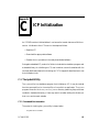
ICP Initialization
C.1 The icpdnld Utility. . . . . . . . . . . . . . . . .
C.1.1 Command Line Invocation . . . . . . . . .
C.1.2 Programmatic Invocation . . . . . . . . . .
C.1.3 Load Files . . . . . . . . . . . . . . . . . . .
C.2 The libicpdnld.so Shareable Library . . . . . . .
C.2.1 Library Components . . . . . . . . . . . . .
C.2.1.1 Function GetDownloadVersion . . . .
C.2.1.2 Function DownloadICP . . . . . . . .
C.2.2 Compiling and Linking With libicpdnld.so .
Index
DC 900-1512C
78
79
79
80
83
.
.
.
.
.
.
.
.
.
.
.
.
.
.
.
.
.
.
.
.
.
.
.
.
.
.
.
.
.
.
.
.
.
.
.
.
.
.
.
.
.
.
.
.
.
.
.
.
.
.
.
.
.
.
.
.
.
.
.
.
.
.
.
.
.
.
.
.
.
.
.
.
.
.
.
.
.
.
.
.
.
.
.
.
.
.
.
.
.
.
.
.
.
.
.
.
.
.
.
.
.
.
.
.
.
.
.
.
.
.
.
.
.
.
.
.
.
.
.
.
.
.
.
.
.
.
.
.
.
.
.
.
.
.
.
.
.
.
.
.
.
.
.
.
.
.
.
.
.
.
.
.
.
83
83
84
86
86
87
87
87
89
91
5
ICP2432 User’s Guide for Solaris STREAMS
6
DC 900-1512C
List of Figures
Figure 1–1:
Typical Data Communications System Configuration . . . . . . . . . . . 18
Figure 3–1:
DLI/TSI Interface in the Freeway Server Environment . . . . . . . . . . . 27
Figure 3–2:
DLITE Interface in an Embedded ICP2432 Environment. . . . . . . . . . 28
Figure 3–3:
DLI_ICP_DRV_INFO “C” Structure. . . . . . . . . . . . . . . . . . . . . 38
Figure 4–1:
ICP_Driver_Info Structure Format. . . . . . . . . . . . . . . . . . . . . . 66
Figure 4–2:
ICP Device State Definitions . . . . . . . . . . . . . . . . . . . . . . . . . 67
Figure B–1:
Sample Output from DDCMP Blocking Multithreaded Program . . . . . 81
Figure B–2:
Sample Output from DDCMP Non-Blocking Multithreaded Program . . 82
Figure C–1:
Using fork(2) to Invoke icpdnld Without Blocking . . . . . . . . . . . . . 85
Figure C–2:
Example Load File Contents . . . . . . . . . . . . . . . . . . . . . . . . . 86
DC 900-1512C
7
ICP2432 User’s Guide for Solaris STREAMS
8
DC 900-1512C
List of Tables
Table 2–1:
Protocol Identifiers. . . . . . . . . . . . . . . . . . . . . . . . . . . . . . . 21
Table 3–1:
DLITE Error Codes . . . . . . . . . . . . . . . . . . . . . . . . . . . . . . 43
Table 3–2:
Solaris Errors Mapped to dlerrno . . . . . . . . . . . . . . . . . . . . . . . 44
Table 4–1:
ICP2432 Device Driver Control Codes . . . . . . . . . . . . . . . . . . . . 63
Table 4–2:
ICP_Driver_Info Field Descriptions . . . . . . . . . . . . . . . . . . . . . 67
Table B–1:
Sample Program File Names. . . . . . . . . . . . . . . . . . . . . . . . . . 77
DC 900-1512C
9
ICP2432 User’s Guide for Solaris STREAMS
10
DC 900-1512C
Preface
Purpose of Document
This document describes how to use Protogate’s embedded ICP2432 intelligent communications processor (ICP) in a peripheral component interconnect (PCI) bus computer running in a Solaris STREAMS environment.
Intended Audience
This document is intended primarily for Solaris system managers and applications programmers. Application programmers can use Protogate’s data link interface (DLI) to
communicate with the ICP2432 device driver. The embedded version of the DLI is
called DLITE. It provides dlInit, dlOpen, dlClose, dlWrite, dlRead, and related functions
for accessing the ICP2432. Refer to Chapter 3 for details.
Programmers who wish to interface directly to Protogate’s Solaris STREAMS driver
(described in Chapter 4) should also be familiar with the information contained in
Part I of the STREAMS Programming Guide included in the Solaris documentation set.
Organization of Document
Chapter 1 is an overview of the product.
Chapter 2 describes how to install the ICP2432 software in a Solaris system. This chapter is of interest primarily to system managers.
DC 900-1512C
11
ICP2432 User’s Guide for Solaris STREAMS
Chapter 3 describes the embedded DLITE interface for Solaris. This chapter supplements the Freeway Data Link Interface Reference Guide and is of interest primarily to
programmers who are either porting an existing DLI application (currently operational
in the Freeway server environment) to the embedded DLITE environment, or who are
developing an initial DLITE application for the embedded ICP2432.
Chapter 4 describes the Solaris STREAMS interface to the ICP2432 device driver.
Appendix A describes debug support.
Techpubs —
Don’t delete
the extra
reference
table at end
with the
Solaris
reference
docs.
4/5/99 Leslie:
Add DC-9001512, Solaris
STREAMS
Appendix B describes the multithreaded sample programs.
Appendix C describes ICP initialization using the icpdnld utility.
Protogate References
The following general product documentation list is to familiarize you with the available Protogate Freeway and embedded ICP products. The applicable product-specific
reference documents are mentioned throughout each document (also refer to the
“readme” file shipped with each product). Most documents are available on-line at Protogate’s web site, www.protogate.com.
General Product Overviews
•
•
•
•
Freeway 1100 Technical Overview
25-000-0419
Freeway 2000/4000/8800 Technical Overview
25-000-0374
ICP2432 Technical Overview
25-000-0420
ICP6000X Technical Overview
25-000-0522
Hardware Support
•
•
•
•
•
12
Freeway 1100/1150 Hardware Installation Guide
DC 900-1370
Freeway 1200 Hardware Installation Guide
DC 900-1537
Freeway 1300 Hardware Installation Guide
DC 900-1539
Freeway 2000/4000 Hardware Installation Guide
DC 900-1331
Freeway 3100 Hardware Installation Guide
DC 900-2002
DC 900-1512C
Preface
•
•
•
•
•
•
Freeway 3200 Hardware Installation Guide
DC 900-2003
Freeway 3400 Hardware Installation Guide
DC 900-2004
Freeway 3600 Hardware Installation Guide
DC 900-2005
Freeway 8800 Hardware Installation Guide
DC 900-1553
Freeway ICP6000R/ICP6000X Hardware Description
DC 900-1020
ICP6000(X)/ICP9000(X) Hardware Description and Theory of
Operation
DC 900-0408
•
•
•
ICP2424 Hardware Description and Theory of Operation
DC 900-1328
ICP2432 Hardware Description and Theory of Operation
DC 900-1501
ICP2432 Hardware Installation Guide
DC 900-1502
Freeway Software Installation Support
•
•
•
•
•
•
•
•
Freeway Release Addendum: Client Platforms
DC 900-1555
Freeway User’s Guide
DC 900-1333
Getting Started with Freeway 1100/1150
DC 900-1369
Getting Started with Freeway 1200
DC 900-1536
Getting Started with Freeway 1300
DC 900-1538
Getting Started with Freeway 2000/4000
DC 900-1330
Getting Started with Freeway 8800
DC 900-1552
Loopback Test Procedures
DC 900-1533
Embedded ICP Installation and Programming Support
•
•
•
•
•
•
ICP2432 User’s Guide for Digital UNIX
DC 900-1513
ICP2432 User’s Guide for OpenVMS Alpha
DC 900-1511
ICP2432 User’s Guide for OpenVMS Alpha (DLITE Interface)
DC 900-1516
ICP2432 User’s Guide for Solaris STREAMS
DC 900-1512
ICP2432 User’s Guide for Windows NT
DC 900-1510
ICP2432 User’s Guide for Windows NT (DLITE Interface)
DC 900-1514
Application Program Interface (API) Programming Support
•
•
•
Freeway Data Link Interface Reference Guide
DC 900-1385
Freeway Transport Subsystem Interface Reference Guide
DC 900-1386
QIO/SQIO API Reference Guide
DC 900-1355
DC 900-1512C
13
ICP2432 User’s Guide for Solaris STREAMS
Socket Interface Programming Support
•
Freeway Client-Server Interface Control Document
DC 900-1303
Toolkit Programming Support
•
Freeway Server-Resident Application and Server Toolkit
Programmer’s Guide
DC 900-1325
•
•
OS/Impact Programmer’s Guide
DC 900-1030
Protocol Software Toolkit Programmer’s Guide
DC 900-1338
Protocol Support
•
•
•
•
•
•
•
•
•
•
•
•
•
•
•
•
ADCCP NRM Programmer’s Guide
DC 900-1317
Asynchronous Wire Service (AWS) Programmer’s Guide
DC 900-1324
Addendum: Embedded ICP2432 AWS Programmer’s Guide
DC 900-1557
AUTODIN Programmer’s Guide
DC 908-1558
Bit-Stream Protocol Programmer’s Guide
DC 900-1574
BSC Programmer’s Guide
DC 900-1340
BSCDEMO User’s Guide
DC 900-1349
BSCTRAN Programmer’s Guide
DC 900-1406
DDCMP Programmer’s Guide
DC 900-1343
FMP Programmer’s Guide
DC 900-1339
Military/Government Protocols Programmer’s Guide
DC 900-1602
N/SP-STD-1200B Programmer’s Guide
DC 908-1359
SIO STD-1300 Programmer’s Guide
DC 908-1559
X.25 Call Service API Guide
DC 900-1392
X.25/HDLC Configuration Guide
DC 900-1345
X.25 Low-Level Interface
DC 900-1307
Solaris Documentation
14
Linker and Libraries Guide
Part #805-3050-10, October 1998
Reference Manual
Section 2, “System Calls”
Part #805-3176-10, October 1998, Rev. A
STREAMS Programming Guide
Part #805-4038-10, October 1998
DC 900-1512C
Preface
Document Conventions
The term “ICP,” as used in this document, refers to the physical ICP2432, whereas the
term “device” refers to all of the Solaris software constructs (device driver, I/O database,
and so on) that define the device to the system, in addition to the ICP2432 itself.
Physical “ports” on the ICPs are logically referred to as “links.” However, since port and
link numbers are always identical (that is, port 0 is the same as link 0), this document
uses the term “link.”
Program code samples are written in the “C” programming language.
Document Revision History
The revision history of the ICP2432 User’s Guide for Solaris STREAMS, Protogate document DC 900-1512C, is recorded below:
Revision
Release Date
Description
DC 900-1512A
May 1999
Original release
DC 900-1512B
February 2002
Update document for Protogate, Inc.
DC 900-1512C
March 2002
Correct format errors in Step procedures.
Add references to new freeway models.
Customer Support
If you are having trouble with any Protogate product, call us at (858) 451-0865 Monday
through Friday between 8 a.m. and 5 p.m. Pacific time.
You can also fax your questions to us at (877) 473-0190 any time. Please include a cover
sheet addressed to “Customer Service.”
We are always interested in suggestions for improving our products. You can use the
report form in the back of this manual to send us your recommendations.
DC 900-1512C
15
ICP2432 User’s Guide for Solaris STREAMS
16
DC 900-1512C
Chapter
1
Product Overview
The Protogate ICP2432 data communications product allows PCIbus computers running the Solaris operating system to transfer data to other computers or terminals over
standard communications circuits. The remote site need not have identical equipment.
The protocols used comply with various corporate, national, and international standards.
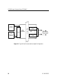
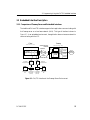
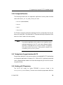
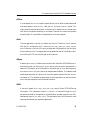
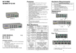
The ICP2432 product consists of the software and hardware required for user applications to communicate with remote sites. Figure 1–1 is a block diagram of a typical system configuration. Application software in the Solaris system communicates with the
ICP2432 by means of the Protogate-supplied device driver.
The icpdnld program (described in Appendix C) is supplied with the product to download the ICP-resident software to the ICP2432.
The ICP controls the communications links for the user applications. The user application program can use the embedded DLITE interface to communicate with the ICP.
The DLITE interface allows the user application to read and write data to the ICP2432
for transmission to or receipt from the communications links, and can change the link
configuration parameters. See Chapter 3.
The user application also has the option of interfacing directly to the Solaris STREAMS
driver, as explained in Chapter 4.
DC 900-1512C
17
ICP2432 User’s Guide for Solaris STREAMS
icpdnld
Program
DLITE
User
Application
Process
Host
Driver
(icp2432sd)
P
C
I
b
u
s
Communication
link
ICP
•
•
•
•
•
•
Data links to
remote computer
or data network
Communication
link
3574
Figure 1–1: Typical Data Communications System Configuration
18
DC 900-1512C
Chapter
2
Software Installation
This chapter describes Protogate’s ICP2432 software installation procedure for
Solaris 7.
2.1 ICP2432 Software Installation Procedure
Step 1: Verify that you have installed one or more ICP2432 boards in your computer,
as described in the ICP2432 Hardware Installation Guide.
Step 2:
Insert the CD-ROM into your system. You may use a web browser to access the
“/cdrom/cdrom0/index.html” file for information about the CD-ROM contents.
Step 3: Use the tar x command to retrieve the files. Use the v option if you wish to display the file names as they are extracted. Some systems require that you use the f option
to identify the peripheral device being used. For example:
tar xvf /cdrom/cdrom0/parts/PF-100/PF-100-0001.tar
Note that the actual tar file name may be different for your system. The files are copied
from the distribution media into the freeway directory.
DC 900-1512C
19
ICP2432 User’s Guide for Solaris STREAMS
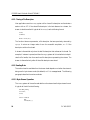
2.2 Loading the ICP2432 STREAMS Driver
After retrieving the files, the Solaris STREAMS driver must be installed in the system
using the icpsetup script file located in the freeway/client/sol_emb/bin directory.
Step 1:
Log in as root.
Step 2:
Change to the freeway/client/sol_emb/bin directory and run the icpsetup script
as follows:
#cd freeway/client/sol_emb/bin
#icpsetup
Step 3:
The computer displays the following prompt:
Will you load the debug mode driver [n]?
The default is to load the non-debug version of the driver. To select the debug mode
driver, enter y. See Appendix A for information on “Debug Support for ICP-resident
Software.”
After you select the driver mode, the driver is loaded in the system. The following confirmation is displayed (for the non-debug mode, 64-bit driver):
ICP2432 64bits Stream Driver (icp2432sd) has been loaded
Note
To change the driver mode, use the same icpsetup sequence as
above. The icpsetup script removes the currently installed driver
and loads the new driver selected in Step 3 above.
20
DC 900-1512C
2: Software Installation
2.3 Protocol or Toolkit Software Installation Procedure
The ppp variables mentioned throughout this section specify the particular
you are using. Refer to Table 2–1.
See the file
“ppptable”: to
add
protocol information as
appendices are
added.
Table 2–1: Protocol Identifiers
Protocol or Toolkit
Protocol Identifier (ppp)
ADCCP NRM
nrm
AWS
aws
BSC3270
bsc32701
BSC2780/3780
bsc3780a
DDCMP
ddcmp2
FMP
fmp
Military/Government
mil3
Protocol Toolkit
sps
STD1200B
s12
X.25/HDLC
x254
1
Except for the readme, release notes, release history, and load configuration
files where ppp is bsc. For example, bscload is used for BSC3270 and
BSC2780/3780.
2 Except for the readme, release notes, and release history configuration files
where ppp is ddc.
3
Some Military/Government files use the identifier “mgn” where n is a Protogate-supplied product designator.
4 Except
for the test directory where ppp is x25mgr.
The following files are in the freeway directory:
•
readme.ppp provides general information about the protocol software
•
relnotes.ppp provides specific information about the current release of the proto-
col software
•
relhist.ppp provides information about previous releases of the protocol software
The load file, pppload, is in the freeway/boot directory.
DC 900-1512C
21
ICP2432 User’s Guide for Solaris STREAMS
The executable object for protocol software is in the freeway/boot directory.
The executable object for the system-services module for protocol software other than
protocol toolkit (xio_2432.mem) is in the freeway/boot directory. The executable object
for the system-services module for the protocol toolkit (xio_2432.mem) is in the freeway/icpcode/os_sds/icp2432 directory.
Source code for the loopback tests is in the freeway/client/sol_dlite/ppp1 directory.
Step 1:
Insert the protocol installation diskette or CD-ROM into your Solaris 7 com-
puter.
Step 2:
Start the installation by running the setup program on the installation diskette
or CD-ROM. Follow the prompts on the screen to install the protocol software.
Step 3:
Using any text editor, edit the load file (freeway/boot/pppload) for your proto-
col. Uncomment the lines associated with ICP2432. Do not change the memory locations (such as 40001200) for the LOAD commands.
Note
If you are installing the X.25 protocol, you must build the CS API
files. A make file is included that performs this operation.
From the freeway/lib/cs_api directory, enter the following command. The newly created file will be placed in the freeway/
client/sol_emb/lib directory.
nmake -f makefile.eso
Continue the installation at Step 4 below.
1. The Military/Government protocols use the freeway/client/test/mil directory.
22
DC 900-1512C
2: Software Installation
Step 4: From the freeway/client/sol_dlite/ppp1 directory, enter the following command:
make
The newly created files are placed in the freeway/client/sol_emb/bin directory.
Step 5: Go to the freeway/client/sol_emb/bin directory. Run the loopback test as
described in Appendix B.
1. The Military/Government protocols use the freeway/client/test/mil directory.
DC 900-1512C
23
ICP2432 User’s Guide for Solaris STREAMS
24
DC 900-1512C
Chapter
Techpubs —
Terminology
Cautions: 1)
use blocking
and nonblocking I/O
(instead of
synchronous
and
asynchronou
s 2) use
“Raw
operation”
rather than
“Raw mode”
3
Programming Using the
DLITE Embedded Interface
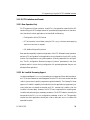
3.1 Overview
This chapter primarily describes the differences between the data link interface (DLI) to
Freeway (as described in the Freeway Data Link Interface Reference Guide) and the
DLITE embedded interface in a Solaris STREAMS system, referred to as “DLITE.”
Changes to the scope and nature of Freeway DLI support are described.
This chapter should be read by application programmers who are doing one of the following:
•
Porting an existing DLI application (currently operational in the Freeway environment) to the embedded DLITE environment.
•
Developing an initial DLITE application in the embedded environment. You
should first read the Freeway Data Link Interface Reference Guide and have it available as your primary reference.
In addition to the Freeway Data Link Interface Reference Guide, the following Protogate
documentation is of interest to application programmers:
•
The applicable protocol-specific programmer’s guide for your application.
DLITE is a new, streamlined interface designed specifically for the embedded ICP2432
board. DLITE provides new capabilities while retaining the majority of the “Freeway
DLI” (henceforth referred to as DLI) capabilities. By using DLITE, developers can concentrate on the communication requirements of the ICP2432 rather than the details
required by the Solaris STREAMS interface and the ICP2432 Solaris STREAMS driver,
DC 900-1512C
25
ICP2432 User’s Guide for Solaris STREAMS
thereby reducing programming complexity and development time. DLITE can be
thought of as a communications pipe to the ICP2432. It is compatible with the existing
Freeway DLI (with caveats described in Section 3.3.2 on page 31). DLITE provides a
high-level open/close/read/write interface to the ICPs. It supports both blocking and
non-blocking I/O. The DLITE interface is thread-safe and supports multiple threads
requesting its services.
Refer to Chapter 4 for programming directly to the Solaris STREAMS interface.
26
DC 900-1512C
3: Programming Using the DLITE Embedded Interface
3.2 Embedded Interface Description
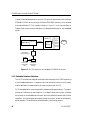
3.2.1 Comparison of Freeway Server and Embedded Interfaces
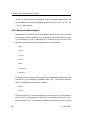
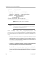
The traditional DLI and TSI interface supports client applications communicating with
the Freeway server on a local-area network (LAN). This type of interface is shown in
Figure 3–1. In an embedded environment, the application does not access a network in
communicating with the ICP.
Freeway
Client
Application DLI TSI
TCP/IP
TCP/IP
Socket Interface
DLI Binary
Configuration File
192.52.107.100
SRA
Msg
TSI Mux
ICP0
ICP1
WAN
Protocols
ICP2
ICP3
3400
Shared Memory
Interface
Ethernet
Industry
Standard Bus
Client
192.52.107.99
TSI Binary
Configuration File
dlicfg
tsicfg
DLI
TSI
DLI Text
Configuration Configuration Configuration
Preprocessor Preprocessor
File
(off-line)
(off-line)
TSI Text
Configuration
File
Figure 3–1: DLI/TSI Interface in the Freeway Server Environment
DC 900-1512C
27
ICP2432 User’s Guide for Solaris STREAMS
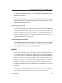
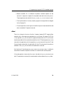
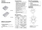
Instead, the embedded application using DLITE communicates directly with the Solaris
STREAMS ICP2432 driver (through the Solaris STREAMS interface), which accesses
the locally attached ICP. This interface is shown in Figure 3–2. In this environment no
Freeway-type communications take place; it is designed specifically for the embedded
system.
ICP0
Solaris
API
PCI
Driver
ICP1
WAN
Protocols
ICP2
ICP3
3576
Client
Application DLITE
PCIbus
Solaris 7
DLITE Binary
Configuration File
dlicfg
DLITE Text
Configuration
File
DLI
Configuration
Preprocessor
(off-line)
Figure 3–2: DLITE Interface in an Embedded ICP2432 Environment
3.2.2 Embedded Interface Objectives
The DLITE interface was designed as a streamlined interface to the ICP2432 supporting
a multithreaded application. It supports only Raw operation protocols, which means
that the application is responsible for all communications with the ICP.
DLITE was designed to maximize portability between existing applications. The objective was an interface that would require “no changes” when porting from a Freeway
environment to an embedded environment. While this objective has been met (for Raw
operation), there are differences between these environments, as well as differences in
system behavior. These differences are addressed in the following sections.
28
DC 900-1512C
3: Programming Using the DLITE Embedded Interface
3.3 DLITE Interface
The DLITE interface is described here in terms of enhanced capabilities, limitations and
caveats, the API itself, and configuration files. Within each context, necessary changes
and any behavior differences are noted.
3.3.1 DLITE Enhancements
3.3.1.1 Multithread Support
DLITE supports a multithread application interface which is thread-safe for both
blocking I/O and non-blocking I/O. Sample multithread programs are provided, as
described in Appendix B.
Caution
Users are not protected from the misuse of threads.
Multithread support is accomplished by serializing access to shared processing and
eliminating or otherwise guaranteeing integrity of global data.
Access is serialized to the following services so that only a single thread can be in the service at any one time:
•
dlInit
•
dlOpen
•
dlClose
•
dlTerm
DC 900-1512C
29
ICP2432 User’s Guide for Solaris STREAMS
The following functions allow application threads concurrent access to the degree specified:
•
dlRead — read requests block if another read for the same session is currently
being serviced
•
dlWrite — write requests block if another write for the same session is currently
being serviced
30
•
dlBufAlloc — multiple thread concurrent access
•
dlBufFree — multiple thread concurrent access
•
dlPoll — request dependent
•
Read complete — blocks at session level
•
Write complete — blocks at session level
•
Read cancel — blocks at session level
•
Write cancel — blocks at session level
•
Session status — multiple thread concurrent access
•
System configuration — multiple thread concurrent access
•
Driver information — multiple thread concurrent access
•
Trace control — multiple thread concurrent access
DC 900-1512C
3: Programming Using the DLITE Embedded Interface
3.3.2 DLITE Limitations and Caveats
3.3.2.1 Raw Operation Only
DLITE supports only Raw operation. As with DLI, Raw operation means that the API
sends nothing to the ICPs except that which is provided by the application for transmission; therefore, the client application must handle all the following:
•
Configuration of the ICP/Protocol
•
ICP and protocol control data (using the DLI OptArgs structure accompanying
each dlRead and dlWrite request)
•
I/O details of the specific protocol
Raw operation especially impacts configuration of the ICP. Whereas Normal operation
performs ICP configuration for the application using information from the DLI configuration file, the application using Raw operation is totally responsible for configuration. The DLI configuration file does not support “protocol” parameters (in fact, their
presence results in errors during configuration file processing because they are not
allowed in Raw operation).
3.3.2.2 No LocalAck Processing Support
Local acknowledgment (LocalAck) processing is not supported. When data is written to
an ICP, the user receives an acknowledgment that the ICP did in fact receive that data
(refer to your protocol-specific programmer’s guide for details). The Freeway DLI does
support a “LocalAck” capability that hides this from the application programmer (previous writes are not posted as complete until DLI receives this LocalAck, then the
LocalAck is thrown away). However, the DLITE user is responsible for receiving each
LocalAck and performing any necessary processing. The DLITE behavior is exactly the
same as when the DLI LocalAck configuration parameter is set to “no”. This generally
implies the client application should post a dlRead after each dlWrite to receive the
expected Local Ack.
DC 900-1512C
31
ICP2432 User’s Guide for Solaris STREAMS
3.3.2.3 AlwaysQIO Support
DLI optionally supported an “AlwaysQIO” feature (applicable only when using
non-blocking I/O), which restricted notification of completed I/O to callback invocations only. If an I/O completed immediately in the I/O request, the completion would
not be reported with the return of the dlRead or dlWrite request. Instead, notification
would be through the user-supplied callback.
DLITE always behaves as if the AlwaysQIO configuration parameter is set to “yes” (nonblocking I/O only). Non-blocking I/O should always return with EWOULDBLOCK
while the I/O completes.
3.3.2.4 Changes in Global Variable Support
DLI maintained three global variables; dlerrno, iICPStatus, and cfgerrno. The global variables iICPStatus and cfgerrno are not supported for DLITE. The iICPStatus value simply
returned the value contained in the ICP status field, which is now available to the
DLITE application in the iICPStatus field from the OptArgs. The information in cfgerrno
is no longer available.
The dlerrno variable is still available, but has been redefined for DLITE as a function call
returning an integer (int _dlerrno()). Reference to dlerrno becomes a function call which
returns the last error for the thread making the call. Note that this definition precludes
using dlerrno as an “L-value” in a “C” expression.
3.3.2.5 dlInit Function No Longer Implied
DLI allowed users to perform dlOpen before calling dlInit (dlInit would be invoked if
required, not a recommended practice). This results in an error when using DLITE.
Processing must be initialized using dlInit before any other service is requested.
32
DC 900-1512C
3: Programming Using the DLITE Embedded Interface
3.3.2.6 Unsupported Functions
The following functions are not supported. Applications invoking these functions
return with the DLI_XX…XX_ERR_NEVER_INIT error.
•
dlControl (see note below)
•
dlListen
•
dlPost
•
dlSyncSelect
DLITE does not support the dynamic building of the DLI configuration file if the .bin
does not currently exist. This means that DLITE expects the binary configuration file to
exist at run time in order to function properly.
Note
Any previous application which used dlControl to perform a programmatic download to the ICP must use an alternate method.
Appendix C illustrates the DownloadICP() function. The application must link with the libicpdnld.so library, which is found in the
lib directory, freeway/client/sol_emb/lib.
3.3.3 The Application Program’s Interface to DLITE
Except where described in the previous sections, the embedded DLITE interface does
not change the application’s interface to DLI. While the DLI interface has remained
intact, changes have been made in both the methods supporting DLI and in the underlying functionality.
3.3.3.1 Building a DLITE Application
The DLITE API library for Solaris STREAMS is libsolem.a, found in the
freeway/client/sol_emb/lib directory. The user must include the preprocessor definition
DC 900-1512C
33
ICP2432 User’s Guide for Solaris STREAMS
“SOLDLITE” when building the application using the Protogate-supplied library and
include header files. In addition the application must also link with the “–lpthreads” and
“–lposix4” system libraries.
3.3.3.2 Blocking and Non-blocking I/O
Implementation of non-blocking I/O has changed in some of the services. In summary,
the following functions use blocking I/O, regardless of the session’s definition of the
asyncIO parameter in the DLI configuration file. These functions do not return to the
application until all processing is completed for the service requested:
•
dlInit
•
dlOpen
•
dlClose
•
dlTerm
•
dlPoll
•
dlBufAlloc
•
dlBufFree
The following functions use non-blocking I/O when requested by the application (that
is, when the asyncIO configuration parameter is set to “yes”). They return to the application immediately after the operation is queued.
•
dlRead
•
dlWrite
Using non-blocking I/O, a successful operation returns OK, and dlerrno has the value of
EWOULDBLOCK . The application is notified of I/O completion through the I/O com-
pletion handler (IOCH). The completed I/O operation is retrieved using a dlPoll request
34
DC 900-1512C
3: Programming Using the DLITE Embedded Interface
for read/write complete. See Section 3.3.3.5 on page 41 for more information on callbacks and I/O completion.
Using blocking I/O, the dlRead and dlWrite functions return ERROR if unsuccessful;
otherwise, they return the number of bytes transferred (not including the ICP and
Protocol Header inserted by DLITE).
3.3.3.3 Changes in DLI/TSI
The lack of a network connection has eliminated the need for some of the client/server
communications between the current DLI and TSI. While the user buffer is not
affected, some data previously in the DLI header (i.e. the Freeway header) and the TSI
header is no longer built by the API. These changes are transparent to the user but may
be noted when examining DLITE trace files.
3.3.3.4 Changes in DLI Functions
No changes are required in the user interface to DLI. Some DLI functions have changed
in their implementation, which might affect the user’s expected behavior of the function. Changes in the affected functions are described below.
dlBufAlloc
Implementation of buffer allocation has changed. Rather than allocating buffers from a
pre-allocated buffer pool managed by TSI, buffer allocation requests presented to
DLITE (using dlBufAlloc) invoke Solaris system memory services to allocate buffers
(using malloc calls). Do not assume any type of buffer initialization. Also, the size
requested in dlBufAlloc can be thought of as the size requested from the system (the
actual size is somewhat larger, which includes some DLITE overhead requirements). If
the application requests one byte for the data buffer size, it should assume only one byte
is returned.
User requests are verified against the MaxBufs and MaxBufSize DLITE configuration
parameters. Requests exceeding either of these return a buffer allocation error.
DC 900-1512C
35
ICP2432 User’s Guide for Solaris STREAMS
Buffers allocated using dlBufAlloc are allocated with room for the ICP and Protocol
header, and a small DLITE work area prefacing the user’s data area. This area is added
to the user’s request; users do not have to account for these requirements in their buffer
request. DLITE also “tags” each buffer, and verifies the buffer was allocated using
dlBufAlloc before it frees the buffer in dlBufFree. Users can not free a buffer they allo-
cated directly from the system using dlBufFree. Buffer alignment requirements for communications with the Solaris STREAMS driver are performed by dlBufAlloc. The buffer
returned is correctly aligned.
Note
The user’s buffer allocation request should be only for the user’s
data; the space required for the ICP and Protocol headers are
“silently” added to the buffer request by dlBufAlloc. If the application is not using the DLITE buffer allocation service, it must
account for the following:
• Sixteen (16) bytes for the protocol header immediately
prefacing the data buffer
• Sixteen (16) bytes for the ICP header immediately prefacing
the protocol header
• Alignment of the buffer address on the correct boundary
dlBufFree
This service has also changed its implementation. In concert with the change in buffer
allocation, a call to dlBufFree returns the requested buffer to the Solaris memory services
(using free). Where previously the user could use the buffer pointer returned with the
successful dlBufFree request (the buffer still existed in the TSI buffer pool), now that
buffer is indeed freed. Any further reference to the buffer results in unpredictable
results. Requests with a NULL buffer pointer and attempts to free a buffer not allocated
with dlBufAlloc return with a buffer deallocation error message.
36
DC 900-1512C
3: Programming Using the DLITE Embedded Interface
dlClose
A close request (dlClose) for a specific session blocks until all other threads have exited
that same session’s close ( dlClose), read (dlRead), and write (dlWrite) request. This
might cause the close thread to block on a blocking I/O request (only for the same session) which is blocked and waiting on its timeout. Users can circumvent this problem
by assuring all I/O is cancelled or completed prior to the close request.
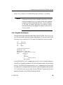
dlInit
The user application must call dlInit before any other DLITE service. If dlInit does not
find the DLI configuration file, it returns the DLI_INIT_ERR_CFG_LOAD_FAILED
error. It does not try to find a DLI source configuration file and perform the configuration processing in-line. The logging and tracing capabilities can fail initialization without inhibiting DLITE from providing all its other services.
dlOpen
A session open (dlOpen) initiates communications with the Solaris STREAMS driver. In
both blocking and non-blocking I/O, dlOpen returns with the result of the operation: a
session ID if successful, an error otherwise. A successful open of a non-blocking operation returns a dlerrno of EWOULDBLOCK and generates a callback. This callback could
be delivered before the API returns from the open request and would contain the correct session ID. This callback can be ignored, since the application can use the completion of the open request to control the open operation.
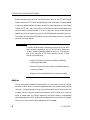
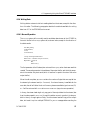
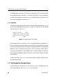
dlPoll
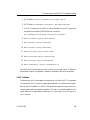
A new poll request of DLI_P0LL_GET_DRV_INFO returns Solaris STREAMS driver
information. The information shown in Figure 3–3 is returned through the pStat
parameter provided by the application (the application provides a pointer to an allocated area of type DLI_ICP_DRV_INFO ). The area used to return this information must
have been allocated by the requesting application.
DC 900-1512C
37
ICP2432 User’s Guide for Solaris STREAMS
typedef struct
{
unsigned long
unsigned long
unsigned long
unsigned long
unsigned char
_DLI_ICP_DRV_INFO
Node;
/* Node assigned */
DeviceNumber;
/* Device Number (ICP) */
NumberOfPorts;
/* Number of ports on ICP */
NumberOfIcps;
/* Number of ICPs installed */
Version[DLI_MAX_STRING + 1];
/* Driver version string. */
}
DLI_ICP_DRV_INFO;
typedef DLI_ICP_DRV_INFO *PDLI_ICP_DRV_INFO;
#define DLI_ICP_DRV_INFO_SIZE sizeof(DLI_ICP_DRV_INFO)
Figure 3–3: DLI_ICP_DRV_INFO “C” Structure
Note
The DLI_POLL_TRACE_STORE and DLI_POLL_TRACE_WRITE
poll requests are not supported by DLITE.
Cancel
Processing
using
dlPoll
(DLI_POLL_READ_CANCEL
and
DLI_POLL_WRITE_CANCEL) is performed differently. The change should be transpar-
ent to existing applications. New applications can optionally take advantage of this
change.
•
A request to cancel reads or writes (dlPoll request cancel read/write) cancels all
outstanding reads or writes for the session at the time the request is received. In
the Freeway DLI, these were cancelled individually, with the buffer pointer and
OptArgs pointer returned for each request.
•
Cancelled I/O is considered as completed. If a user has five read requests queued
and performs a read cancel, a poll would show five reads completed.
•
Cancelled I/O is returned as previously; each request is returned (with buffer
pointer and OptArgs pointer) with each poll requesting the cancel, until all are
returned. Returning the cancelled request reduces the number of I/O completions
by one.
38
DC 900-1512C
3: Programming Using the DLITE Embedded Interface
•
Because cancelled I/O is considered completed, cancelled requests are also
returned in response to requests for completed reads and writes (using dlPoll).
These requests are returned with the DLI_IO_ERR_IO_CANCELLED error code.
•
This implementation of cancel processing supports those applications designed
for the Freeway DLI.
•
The user application should ignore the buffer length and associated buffer data
when a cancelled I/O request is returned.
dlRead
There is no change to the dlRead function. However, because DLITE supports Raw
operation only, it does require an associated OptArgs with each I/O request. DLITE fills
in the supplied OptArgs structure with the appropriate data from the ICP and Protocol
headers associated with the read data received from the ICP. Read requests (dlRead) are
returned to the application with the supplied OptArgs structure built from the ICP and
Protocol header received with the data buffer. All the ICP and protocol information is
available in the OptArgs structure when the read buffer is returned.
Non-blocking I/O should expect an EWOULDBLOCK error upon return. A callback is
issued when the read is completed. A callback is invoked for each read completion.
If the read operation is returned with an error, the data in the OptArgs structure is not
valid. The application must verify the read operation before referencing OptArgs data.
DC 900-1512C
39
ICP2432 User’s Guide for Solaris STREAMS
Note
As with the DLI interface, read requests with a NULL buffer
pointer result in DLITE allocating and returning a read buffer. The
address of the buffer allocated is returned in the supplied buffer
pointer upon return from the call. This is true for both blocking
and non-blocking I/O. The user that wants a DLITE allocated
buffer should ensure the buffer pointer supplied with the dlRead
call is NULL.
dlTerm
Termination processing (dlTerm) releases resources and terminates DLITE. Any active
I/O is cancelled when dlTerm is called. Data buffers associated with the cancelled I/O are
deallocated if those buffers were allocated by DLITE (using dlBufAlloc). OptArgs buffers
are not deallocated. The application should cancel all I/O before terminating.
The dlTerm function sleeps for 1–2 seconds (not including any time required in the cancelling of active I/O) to allow threads which might have been active previous to the termination request to exit.
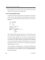
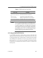
dlWrite
As with dlRead, dlWrite requires an associated OptArgs structure with the write request.
DLITE builds the ICP and Protocol headers, which preface every application buffer (see
dlBufAlloc), from information supplied in this OptArgs structure. Specifically, DLITE
does the following for Raw operation writes:
1. ICP->usClientID = htons (OptArgs->usICPClientID);
2. ICP->usServerID = htons (OptArgs->usICPServerID);
3. ICP->usCommand = htons (OptArgs->usICPCommand);
4. ICP->usParms[0-2] = htons (OptArgs->usICPParms[0-2]);
40
DC 900-1512C
3: Programming Using the DLITE Embedded Interface
5. DLITE adds ICP->iStatus = LittleEndian ? htons (0x4000) : htons (0);
6. DLITE adds ICP->usDataBytes = htons (BufLen + DLI_PROT_HDR_SIZE);
7. If the ICP command is an Attach, or a Write Expedite, the node ID (previously
retrieved from the Solaris STREAMS driver) is stored in:
ICP->usParam[0] ( ICP->usParms[0] = htons( Session->drvNodeID ) )
8. PROT->usCommand = OptArgs->usProtCommand;
9. PROT->iModifier = OptArgs->iProtModifier;
10. PROT->usLinkID = OptArgs->usProtLinkID;
11. PROT->usCircuitID = OptArgs->usProtCircuitID;
12. PROT->usSessionID = OptArgs->usProtSessionID;
13. PROT->usSequence = OptArgs->usProtSequence;
14. PROT->usXParms[0-1] = OptArgs-> usProtXParms [0-1]);
Non-blocking I/O should expect an EWOULDBLOCK error upon return. A callback is
issued when the write is completed. A callback is invoked for each write completion.
3.3.3.5 Callbacks
Callbacks occur only in those sessions configured for non-blocking I/O. They represent
the completion of an I/O activity; signaling the application to perform actions dependent on that I/O completion. In the DLITE interface, this operation might be a dlPoll to
retrieve session status to ascertain the session’s I/O state, or to request read/write completes. Blocking I/O applications receive their I/O upon return from the dlRead or
dlWrite function.
DC 900-1512C
41
ICP2432 User’s Guide for Solaris STREAMS
Callbacks are issued in the context of their own thread. Only one callback thread exists
in each DLITE process. Callbacks are delivered sequentially; they are never reentered by
another callback.
Caution
As the callback operates in the context of its own thread, the application must protect itself with data referenced by its callback processing and processing of other, concurrent, threads.
There is no difference between the “main” callback and the “session” callback. They are
initiated sequentially by DLITE. For sake of efficiency, Protogate recommends the user
make use of only one.
To maintain conformity with the existing DLI, callbacks are delivered upon completion
of dlOpen processing. Although dlOpen processing does not generate a callback from the
system (i.e., an I/O completion port thread is not “kicked-off”) the API does, just prior
to exiting the dlOpen processing, emulate the event by placing a “callback” request in an
internal callback queue for delivery to the application.
In a similar manner, callbacks on dlClose requests are generated and delivered by the
API.
The callback thread runs at a higher priority. This ensures that callbacks do not backup
on the delivery queue. This backup would occur when the application processes more
than one I/O completion event in the callback routine (e.g., processing more than one
read/write compete in a single invocation of the application callback routine). At a
higher priority, the application callback processing can process as many (or as few) as
design dictates without regard to a queue backup.
42
DC 900-1512C
3: Programming Using the DLITE Embedded Interface
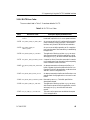
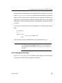
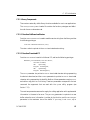
3.3.3.6 DLITE Error Codes
The error codes listed in Table 3–1 have been added to DLITE.
Table 3–1: DLITE Error Codes
Value
DLITE Error Code
–10211 DLI_OPEN_ERR_ICP_INVALID_S
TATUS
Description and Recommended Action
Returned by dlOpen(). The ICP has not been downloaded with a protocol or is in a non-operational state.
–10231 DLI_OPEN_ERR_NO_DRV_INFO
An error occurred in the I/O interface while requesting
Solaris STREAMS driver information. Terminate the
interface, verify Solaris STREAMS driver installation.
–10232 DLI_OPEN_ERR_NO
An error occurred while requesting an I/O completion
port from the system. Terminate and try re-establishing
the application.
CMPLT_PORT
–10518 DLI_READ_ERR_NO_OPTARG
The application failed to provide an OptArgs structure
with the read request. Modify the application to build
and supply an OptArgs structure with each read request.
–10721 DLI_POLL_ERR_INVALID_STATE A request for driver information was made for a session
not currently open. Open the session before requesting
Solaris STREAMS driver information.
–10902 DLI_BUFA_ERR_SIZE_EXCEEDE
D
–11003 DLI_BUFF_ERR_NONE_ALLOC
An attempt was made to allocate more buffers, or a
buffer of greater size, than that defined in the DLI configuration file. Modify the application to adhere to sizes
defined in the DLI configuration file.
An attempt was made to deallocate a buffer when none
were allocated. Modify application to account for used
buffers.
–11004 DLI_BUFF_ERR_ALREADY_FREE Returned by dlBufFree(). The buffer specified has
already been released.
–11918 DLI_WRIT_ERR_NO_OPTARG
The application failed to provide an OptArgs structure
with the write request. Modify the application to build
and supply an OptArgs structure with each write
request.
–12003 DLI_IO_ERR_IO_CANCELLED
The read or write request was cancelled at the request
of the user application.
DC 900-1512C
43
ICP2432 User’s Guide for Solaris STREAMS
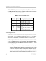
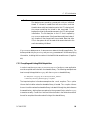
All Solaris STREAMS system errors are mapped into existing DLI error codes (dlerrno)
so the application can recognize the error condition and react accordingly. The errors
are mapped to dlerrno as described in Table 3–2.
Table 3–2: Solaris Errors Mapped to dlerrno
Solaris Value
Solaris Error
Code
Applicable dlerrno Codes
5
EIO
DLI_READ_ERR_IO_FATAL
DLI_WRIT_ERR_IO_FATAL
DLI_POLL_ERR_IO_FATAL
13
EACCES
DLI_READ_ERR_UNBIND
DLI_WRIT_ERR_UNBIND
12
19
37
ENOMEM DLI_READ_ERR_INTERNAL_DLI_E
ENODEV RROR
ECHRNG DLI_WRIT_ERR_INTERNAL_DLI_E
RROR
DLI_POLL_ERR_IO_FATAL
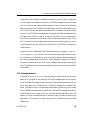
3.3.4 Configuration Files
DLITE uses only the DLI configuration files (TSI configuration files are not used and
are not required). The DLI configuration file must specify “protocol = raw ” in the session
sections. With this specification, no parameters are allowed in the protocol section.
The DLI configuration file has been changed to include parameters previously specified
in the TSI configuration file (which is no longer used). These parameters are required
to maintain conformity with those applications porting from DLI to DLITE. This file
has been changed as follows:
MaxBuffers — This parameter has been added to the “main” section. It replaces the
MaxBuffers parameter previously defined in the TSI configuration file. This value
is returned in the usMaxBufs field of the configuration parameters returned in
response to a dlPoll for system configuration. Operationally, this value limits the
number of buffers the user can have outstanding using the dlBufAlloc function. If
44
DC 900-1512C
3: Programming Using the DLITE Embedded Interface
not explicitly defined in the DLI configuration file, the MaxBuffers parameter
defaults to 1024.
MaxBufSize — This parameter has been added to the “main” section. It replaces the
MaxBufSize parameter previously defined in the TSI configuration file. This value
is returned in the iMaxBufSize field of the configuration parameters returned in
response to a dlPoll for system configuration. Operationally, this value represents
the greatest size an application can request using dlRead, and defines the buffer
size used when a dlRead request is made without specifying a buffer (the API allocates and returns this buffer to the application). If not explicitly defined in the
DLI configuration file, the MaxBufSize parameter defaults to 1024.
MaxBufSize — This parameter has been defined in the “session” section of the DLI con-
figuration file. It replaces the MaxBufSize parameter previously defined in the TSI
configuration file (“connection” section). This value is returned in the
usMaxSessBufSize field of the session parameters returned in response to a dlPoll
for session status. Operationally, this value represents the greatest size an application can request to be written using dlWrite. If not explicitly defined in the DLI
configuration file, the MaxBufSize parameter defaults to 1024.
TSICfgName — The TSI configuration file is no longer used.
3.3.4.1 General Application Error File
DLITE creates an application error file “_DLITERR.TXT” which contains descriptive
run-time errors. Regardless of log and trace levels defined in the DLITE configuration
file, the error file is created in the directory where the application is started. It is a circular file containing a maximum of 1000 entries.
DC 900-1512C
45
ICP2432 User’s Guide for Solaris STREAMS
46
DC 900-1512C
Chapter
4
Programming Using the
Solaris STREAMS Interface
Protogate’s API layers are designed to free developers from the often-difficult programming details of an operating system and the interface details of the protocol software on
the ICP. Protogate’s API layers take care of tasks such as queuing I/O requests, buffer
allocation (with properly aligned I/O buffers), building protocol headers, endian translation, session management, and others. Using the DLITE interface described in
Chapter 3 allows developers to concentrate more on their specific applications rather
than the difficult communication and programming details associated with transferring data from one system to the next via a wide-area network. Protogate strongly
encourages users to implement their applications using the DLITE interface; however,
users who wish to bypass Protogate’s API layers and use the Solaris system services
directly may do so, although many of the functions provided by the DLITE will need to
be “reinvented” in the user application. This chapter provides the information necessary to build Solaris STREAMS applications.
4.1 General STREAMS Information
Programmers who use Protogate’s ICP2432 embedded PCI product for Solaris
STREAMS should be familiar with the information contained in Part I of the STREAMS
Programming Guide included in the Solaris documentation set. The man pages for
streamio(7I) also contain information about programming in the STREAMS environ-
ment, and in particular the ioctl codes recognized by the stream head. There are a few
important issues that affect the applications developer when working with the ICP2432
under STREAMS. These are discussed below.
DC 900-1512C
47
ICP2432 User’s Guide for Solaris STREAMS
4.1.1 Byte-Stream vs. Message-Based Operation
The STREAMS framework does not recognize any message or record boundaries in the
data. Data is simply interpreted as a byte stream, and it is up to the application to
decompose the data into distinct records and/or messages. For example, if a user application operating on a stream passes a 1KB buffer to the read(2) system call, the
STREAMS framework will return 1KB bytes of data to the application if it is available,
even if a record is only 64 bytes long. The application must then decompose the 1KB
data buffer into 16 individual records. This is an important consideration because the
interface between the ICP2432 and the host device driver is message-based; user applications communicate with the ICP2432 (through the device driver) via messages.
Fortunately, the STREAMS framework provides a way to use message-based communication on a stream. putmsg(2) and getmsg(2) can be used to send and receive messages,
respectively, between a user application and the stream head. Alternatively, the
I_SRDOPT ioctl command can be used to change the default operation of a stream from
byte-stream oriented to message oriented. See streamio(7I) for more information on this
ioctl function.
Note
Protogate’s DLITE API layer uses the I_SRDOPT ioctl function to
change the default operation of STREAMS to message based, using
the RMSGN flag.
4.1.2 Error Notification
Programmers in the UNIX environment are familiar with the concept of a “delayed
write” when writing data to a regular disk file. That is, when the write(2) system call
completes, it indicates that the user’s data has been successfully transferred to a block in
the Buffer Cache; but it does not necessarily imply that the user’s data has actually been
written to the corresponding block on the disk drive itself. A similar situation exists in
the STREAMS environment. Successful completion of a write(2) system call does not
48
DC 900-1512C
4: Programming Using the Solaris STREAMS Interface
imply that the user’s data was successfully transferred to the ICP. Rather, it means that
the user’s data was successfully copied into a STREAMS message block and is under
control of the kernel as it passes through the stream. If an error should occur before the
data is transferred to the ICP2432, the user application will have no way of determining
this. This is true for the read side of the stream as well. For example, if a buffer overflow
occurs (i.e. the ICP2432 has a message that is larger than the buffer size selected by the
user application), there is no way to convey this information to the user application,
other than to shut down the entire stream (which the device driver does not do). Therefore, it is imperative that user applications have some sort of peer-to-peer error checking implemented, and that they do not rely solely on the STREAMS framework for
reliable delivery.
Whenever an error is detected by the ICP2432 device driver, it is logged in /var/adm/messages using the cmn_err(9F) function. This file should be checked periodically for prob-
lem notifications. For some errors, such as the buffer overflow described above, the
error is simply logged and no further action is taken. Severe errors cause the ICP2432 to
be reset by the device driver, and an M_ERROR message is sent up each stream open to
the ICP, effectively rendering the streams useless (EBADFD is the error code returned in
this situation).
4.1.3 System Performance
As implied in Section 4.1.2, a write(2) request causes the stream head to copy the user’s
data from an I/O buffer in User Space into a STREAMS message buffer in Kernel Space.
When the STREAMS message containing the user’s data arrives at the device driver, the
driver must again copy the data from the STREAMS message into a suitable DMA
buffer. The inverse is true on the read side; received data is copied from a DMA buffer
into a STREAMS message, and then copied from the STREAMS message into a user I/O
buffer during the read(2) system call. Thus, two data copies are required for every I/O
request. This may hinder performance if unusually large I/O buffers are used by user
applications. The maximum I/O buffer allowed by the ICP2432 device driver is 8KB
(8192 bytes).
DC 900-1512C
49
ICP2432 User’s Guide for Solaris STREAMS
4.1.4 Message Cancellation
Because UNIX I/O is inherently synchronous in nature, UNIX does not provide a
mechanism for cancelling individual messages. In the STREAMS environment, however, an application may use the I_FLUSH ioctl function to cancel a set of messages in
the stream (see streamio(7I)).
Note
Protogate does not recommend using the I_FLUSH ioctl function
within applications except under catastrophic conditions.
Note
The ICP2432 device driver does not differentiate between
I_FLUSH and I_FLUSHBAND requests. Either one causes all messages of the indicated type (i.e. read and/or write) to be flushed
from the message queues. See streamio(7I) for more information on
these two requests.
4.1.5 Synchronous Polling and Signal Delivery
UNIX I/O is inherently synchronous in nature. That is, when an application makes an
I/O request, the requesting thread will block on the system call until the request is complete. For applications controlling multiple file descriptors, the poll(2) system call may
be used to determine what actions may be performed on a set of file descriptors. Consult the Solaris Reference Manual for information on the use of poll(2).
Alternatively, applications may use the I_SETSIG ioctl function to instruct the stream
head to send a SIGPOLL signal to the application whenever a pollable event occurs.
Consult the STREAMS Programming Guide, streamio(7I), and signal(5) for more information on the I_SETSIG ioctl function and the SIGPOLL signal.
50
DC 900-1512C
4: Programming Using the Solaris STREAMS Interface
If a stream is opened using the O_NONBLOCK flag (see open(2)), I/O requests will never
block. If an I/O request is made that would cause a thread to block, –1 is returned to the
caller and errno is set to EWOULDBLOCK.
Applications may use a combination of the above three features to implement an asynchronous I/O mechanism. For example, Protogate’s DLITE API layer attempts to
immediately perform a user I/O request (if no previous requests are still pending). If
EWOULDBLOCK is returned, the message is queued. When the request can be satisfied,
the stream head delivers a SIGPOLL signal to the process. The SIGPOLL signal handler
in DLITE then uses the poll(2) system call to determine on which streams I/O may be
performed. The appropriate request is then issued.
Another method of implementing asynchronous I/O is to create new threads that handle the I/O. The threads might block on an I/O request, but the main thread that created
them is free to do other processing while the I/O requests are active.
4.2 Function Mappings
This section describes how a user application interfaces with the ICP2432 device driver
using the STREAMS framework. It is not intended to be a STREAMS programming
tutorial; users who bypass Protogate’s API layers are assumed to already know how to
write STREAMS applications. This section merely lists the functions used to communicate with the ICP (via the device driver) and the actions performed. Consult the
STREAMS Programming Guide included with the Solaris documentation for information on how to program in the STREAMS environment.
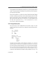
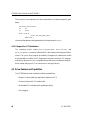
4.2.1 Opening the ICP
Before a user application can perform any I/O transactions with the ICP, a file descriptor to the ICP must be obtained. This is done by opening the ICP using the open(2) system call. A typical call to open(2) would look like the following:
DC 900-1512C
51
ICP2432 User’s Guide for Solaris STREAMS
int fd;
...
fd = open( "/dev/icp1",
O_RDWR | O_NONBLOCK,
0 );
One of the parameters to the open(2) function is the device path, which has the form
/dev/icpN, where ‘N’ represents the ICP number (0, 1, …, 15). The special character
device files are created by the device driver when it is installed. Note that these are
cloneable devices (see below).
The second parameter is a set of flags describing how the device should be opened. Note
that normal UNIX file access control is in effect when the device is opened. For example, if the device is opened for read-only access and then an application attempts to
write to the device, the write request will fail. In the example above, the O_RDWR flag
opens the device with read/write access. The O_NONBLOCK flag specifies that I/O
requests are to be performed asynchronously (i.e. without blocking).
The third function parameter is unused.
If open(2) completes successfully, fd contains the file descriptor representing the opened
stream; otherwise –1 is returned and errno is set appropriately. The file descriptor is
used in subsequent system calls that access the stream.
The special character device files representing the ICP2432s (e.g. /dev/icp1) are created
when the device driver is installed. To communicate with a particular ICP, the associated device file must be opened as described above. However, these device files represent “cloneable” devices. During the open(2) request, a new stream is created to the
device. In addition, the minor device number passed to the driver’s open(9E) routine is
dynamically changed so that each stream represents a separate device. Thus, a unique
stream is created each time the device is opened. This means that individual streams to
an ICP cannot be shared between processes except under explicit program control (for
example, by forking a child process that inherits the file descriptors of its parent). However, threads within a process have access to the same set of file descriptors, so a stream
52
DC 900-1512C
4: Programming Using the Solaris STREAMS Interface
may be shared among different threads within a process at any time (provided the file
descriptors are global to all the threads).
The important thing to remember in the above paragraph is that each open(2) call on an
ICP’s device file produces a separate and distinct stream to the device. Once a stream is
created, it is possible to duplicate the file descriptor that references the stream (using
the dup(2) or fork(2) system calls), but attempting to open the ICP’s device file a second
time creates another unique stream to the device, with a different minor number
assigned to the new stream.
Note
No special device files are created for the streams as they are
assigned unique minor numbers. Only the “cloneable” device files
will be seen in the /dev directory hierarchy.
It should be mentioned that Solaris uses what Sun Microsystems calls “persistent”
device numbering, meaning that device numbers will not normally change when a system is rebooted. For example, suppose a system has one ICP2432 installed in PCI slot 4.
This device shows up in the device hierarchy as /dev/icp0. Suppose a second board is
then installed in PCI slot 1. When the system is rebooted, the ICP2432 in slot 4 is still
recognized as /dev/icp0 while the new board in slot 1 is recognized as /dev/icp1. Consult
the Solaris documentation for more information on persistent device numbering. To
determine which boards are assigned which device numbers, the –l option may be used
with the ls command. The entries in the /dev directory hierarchy are symbolic links to
the actual device entries in the /devices directory hierarchy. The PCI slot number is
given in a special file’s entry in the /devices directory.
DC 900-1512C
53
ICP2432 User’s Guide for Solaris STREAMS
4.2.2 Closing a File Descriptor
User applications use the close(2) system call to close a file descriptor and terminate a
session with an ICP. If the closed file descriptor is the last reference to a stream, the
stream is also dismantled. A typical call to close(2) has the following format.
int fd;
int Status;
...
Status = close( fd );
The function takes one parameter, a file descriptor that was previously returned by
open(2). It returns an integer value of zero for successful completion, or –1 if the
descriptor could not be closed.
A stream is dismantled only when the last file descriptor that references it is closed. For
example, if a stream is opened, and then the dup(2) system call is invoked twice to duplicate the file handle, then there are three file descriptors representing the stream. The
stream is dismantled only after all three file descriptors are closed.
4.2.3 Reading Data
The method used to read data from the stream head depends on whether the stream is
being used in byte-stream mode (the default) or if it is message-based. The following
paragraphs describe the various methods.
4.2.3.1 Byte-Stream Operation
The read(2) system call is used to read data from the stream head in byte-stream format.
A typical call looks like the following.
char Bfr[ 1024 ];
int Count;
int fd;
...
Count = read( fd,
Bfr,
sizeof( Bfr ) );
54
DC 900-1512C
4: Programming Using the Solaris STREAMS Interface
The first parameter is the file descriptor returned from open(2) when the stream was first
created. The second parameter is the address of the input buffer, and the third parameter is the size of the input buffer.
When the call completes, Count contains the number of bytes that were read. Because
the stream is operating in byte-stream mode, the stream head will transfer a full 1024
bytes into the user buffer if that much data is available. If a full 1024 bytes are not available, the stream head transfers what it can and returns. If no data is available, the call
will either block (synchronous I/O) or –1 will be returned with errno set to
EWOULDBLOCK (asynchronous operation).
4.2.3.2 Message-Based Operation
There are two ways in which message data can be read from a stream. The most
straight-forward method is to use the getmsg(2) system call. A typical call has the following format.
char
Bfr[ 1024 ];
struct strbuf DataInfo;
int
fd;
int
Flags;
int
Status;
...
DataInfo.buf = Bfr;
DataInfo.maxlen = sizeof( Bfr );
Flags
= 0;
Status
= getmsg( fd,
NULL,
&DataInfo,
&Flags );
Once again, the first parameter is the file descriptor returned by open(2) when the
stream was created. The second and third parameters are pointers to a strbuf structure
for control information and data, respectively. The strbuf structure contains three fields.
The maxlen field is the size of the input buffer and the buf field is a pointer to the buffer.
The len field is set by the stream head before returning. The final parameter to getmsg(2)
is a pointer to a set of flags that can be used to modify the behavior of getmsg(2). The
DC 900-1512C
55
ICP2432 User’s Guide for Solaris STREAMS
stream head also sets the flags accordingly prior to returning. See the Solaris Reference
Manual for more information on how the flags are interpreted.
The second parameter in the above example is NULL because the ICP2432 device driver
does not generate any control information. However, other user-supplied STREAMS
modules that have been pushed onto the stream might do so.
On return, Status contains either zero for success, or –1 to indicate an error. The len field
of the DataInfo structure contains the number of bytes read from the stream (i.e. the size
of the message). This value will be less than or equal to the value in the maxlen field.
This first method of reading messages has the advantage that both read(2) and getmsg(2)
can be used interchangeably within an application to read data from the stream in
either byte-stream format or message format as desired. This method also has the
advantage that control information can be passed from the stream to the application
(via M_PROTO STREAMS messages). The ICP2432 device driver does not generate
M_PROTO messages, but other user-supplied modules pushed onto the stream are free
to do so.
The second method for reading message data involves the use of the I_SRDOPT ioctl
function (see streamio(7I)). After the stream is created (via open(2)), the I_SRDOPT ioctl
function is used to change the default operating characteristics of the stream head from
byte-stream oriented to message-based. Once this is done, the read(2) system call may be
used as normal (see Section 4.2.3.1). However, because the stream head is operating in
message-based mode, it does not unconditionally transfer 1024 bytes (using the example of Section 4.2.3.1) to the user buffer if it is available, but terminates the transfer on
a STREAMS message boundary. This is the method used in Protogate’s DLITE API
layer. See the STREAMS Programming Guide for more information.
The maximum message length that can be read by the device driver is 8192 bytes. See
Section 4.2.5.1 for instructions on how to set the read buffer size used by the ICP2432
device driver.
56
DC 900-1512C
4: Programming Using the Solaris STREAMS Interface
4.2.4 Writing Data
Writing data to a stream is similar to reading data from the stream, except for the direction of transfer. The following paragraphs describe the methods available for writing
data to an ICP in the STREAMS environment.
4.2.4.1 Normal Operation
The write(2) system call is normally used to send data downstream to the ICP2432. Its
format is similar to the read(2) system call, as shown below, except for the direction of
the data transfer.
char Bfr[ 1024 ];
int BytesSent;
int fd;
int XferCount;
...
<Set up the output buffer here.>
XferCount = <Number of bytes to send>;
BytesSent = write( fd,
Bfr,
XferCount );
The first parameter is the file descriptor returned from open(2) when the stream was first
created. The second parameter is the address of the output buffer, and the third parameter is the number of bytes to send (which is less than or equal to the size of the entire
output buffer).
When the call completes, BytesSent contains the number of bytes that were copied into
the stream by the stream head (or –1 on error). If no kernel memory is available for the
user data, the call will either block until memory becomes available (synchronous I/O)
or –1 will be returned with errno set to EWOULDBLOCK (asynchronous operation).
In theory, the stream head might only copy part of the output data into the stream (less
than the value passed in XferCount), though this seldom occurs in practice. It is also possible in theory—though again unlikely—that the stream head will copy all the output
data, but break it up into multiple STREAMS M_DATA messages before sending the
DC 900-1512C
57
ICP2432 User’s Guide for Solaris STREAMS
data downstream. Either of these scenarios will cause problems since the interface
between the ICP2432 and host driver is message-based.
4.2.4.2 Preserving Message Boundaries
To absolutely guarantee that message boundaries are preserved when writing data to a
stream, the putmsg(2) system call may be used to send messages. The format is similar to
the getmsg(2) system call described earlier, as shown below, except for the direction of
data transfer.
char
Bfr[ 1024 ];
struct strbuf DataInfo;
int
fd;
int
Status;
...
<Set up the output buffer here.>
DataInfo.buf = Bfr;
DataInfo.maxlen = sizeof( Bfr );
DataInfo.len = <Number of bytes to send>;
Status
= putmsg( fd,
NULL,
&DataInfo,
0 );
The first parameter is the file descriptor returned by open(2) when the stream was created. The second and third parameters are pointers to a strbuf structure for control
information and data, respectively. The strbuf structure contains three fields. The
maxlen field is unused during write requests, but the len field must be set to the number
of bytes to write. The buf field is a pointer to the output buffer. The final parameter to
putmsg(2) is a set of flags that can be used to modify the behavior of putmsg(2). See the
Solaris Reference Manual for more information on how the flags are interpreted and for
complete information on putmsg(2).
The second parameter in the above example is NULL because the ICP2432 device driver
does not recognize M_PROTO message types (the type of STREAMS message generated
by the stream head for control information). Any M_PROTO messages received by the
device driver are discarded.
58
DC 900-1512C
4: Programming Using the Solaris STREAMS Interface
When putmsg(2) returns, Status contains either zero for success or –1 for failure.
Caution
If the amount of kernel memory available is insufficient to contain
the entire message, the putmsg(2) system call will block regardless
of whether the stream was opened with the O_NONBLOCK flag set.
In this case, the stream head waits until sufficient memory
becomes available for the message. Partial data is never sent when
putmsg(2) is used.
4.2.4.3 Expedited Write Requests
User applications may occasionally need to send high-priority data. The putpmsg(2) system call may be used to send priority-band data requests. This function has the exact
format as putmsg(2) (see Section 4.2.4.2) except for the addition of the priority band.
char
Bfr[ 1024 ];
struct strbuf DataInfo;
int
fd;
int
Status;
...
<Set up the output buffer here.>
DataInfo.buf = Bfr;
DataInfo.maxlen = sizeof( Bfr );
DataInfo.len = <Number of bytes to send>;
Status
= putpmsg( fd,
NULL,
&DataInfo,
1,
// Priority band one.
MSG_BAND );
Normal STREAMS M_DATA messages have a priority of zero. However, streams provides 255 priority bands (numbered 1–255, with the greater number having the higher
priority). The STREAMS framework queues M_DATA messages by priority band, with
the higher-priority messages toward the head of the queue. Messages are also queued in
FIFO order within each priority band. See the STREAMS Programming Guide for
detailed information on the STREAMS queuing methods.
DC 900-1512C
59
ICP2432 User’s Guide for Solaris STREAMS
From the ICP2432 device driver’s point-of-view, the priority band is irrelevant. Any
M_DATA message received by the driver that has a priority greater than zero is treated
as an expedited write request. Because the device driver does its own internal queuing
of user requests, the last statement implies that it is possible—though extremely
unlikely—for a message with a priority of one to be transferred to the ICP before a message with higher priority; it all depends on when the driver begins processing the message. That is, if the driver begins processing the message with priority one before a
higher-priority message is placed on its queue, the message with priority band one will
be sent to the ICP first. However, the STREAMS framework will always queue messages
by priority, and the driver always sends expedited write requests to the ICP before any
normal messages.
Note
Expedited write requests are global to the driver, and not restricted
to the stream on which they are issued. If multiple streams are
opened to an ICP and an expedited write request is received by the
driver, the expedited write is transferred to the ICP before any
normal-priority messages that the driver has queued.
The method described above for sending priority-band data has one serious drawback.
Priority-band data messages are subject to the same STREAMS flow control as normal
data messages. To send a high-priority STREAMS message to the driver that is not subject to flow control, a control portion must be added to the putmsg(2) (or putpmsg(2))
function call, and the Flags parameter must be set accordingly. The following example
sends an out-of-band data message to the ICP.
60
DC 900-1512C
4: Programming Using the Solaris STREAMS Interface
char
Bfr[ 1024 ];
struct strbuf CtrlInfo;
struct strbuf DataInfo;
int
fd;
PCPROTO_Command PcCmd = PCPROTO_Write_Expedite;
int
Status;
...
<Set up the output buffer here.>
CtrlInfo.buf = (char*) &PcCmd;
CtrlInfo.maxlen = sizeof( PcCmd );
CtrlInfo.len = sizeof( PcCmd );
DataInfo.buf = Bfr;
DataInfo.maxlen = sizeof( Bfr );
DataInfo.len = <Number of bytes to send>;
Status
= putmsg( fd,
&CtrlInfo,
&DataInfo,
RS_HIPRI );
The RS_HIPRI flag informs the stream head that a high-priority STREAMS message is
to be built. The stream head creates an M_PCPROTO message and copies the control
buffer—the contents of PcCmd in the above example—into the message block. The
stream head then attaches an M_DATA continuation block to the message, and copies
the data buffer into the M_DATA block. The entire message is then sent to the device
driver. Because M_PCPROTO is a high-priority STREAMS message type, it will be sent
immediately downstream without any flow control constraints.
The control portion for an expedited write request consists of only a
PCPROTO_Command type with the value PCPROTO_Write_Expedite. These are defined
in the icp2432sol.h header file included on the product distribution media.
Caution
Users should not use priority band 255 in their applications. When
an M_PCPROTO message is received by the driver that indicates an
expedited write request, the control portion is discarded, and the
priority band of the data portion is implicitly changed to 255 by
the device driver before the message is processed.
DC 900-1512C
61
ICP2432 User’s Guide for Solaris STREAMS
Caution
If the amount of kernel memory available is insufficient to contain
the entire message, the putmsg(2) and putpmsg(2) system calls will
block regardless of whether the stream was opened with the
O_NONBLOCK flag set. In this case, the stream head waits until
sufficient memory becomes available for the message. Partial data
is never sent when putmsg(2) or putpmsg(2) is used.
4.2.5 I/O Control Functions
User applications might sometimes need to communicate directly to the device driver
or other STREAMS modules to obtain information or perform control functions. The
ioctl(2) system call is used to make such requests. In particular, in the STREAMS envi-
ronment the I_STR ioctl function is used to send a special request to the ICP2432 device
driver (see streamio(7I) for information on the I_STR ioctl request). In addition to the
normal I_STR method of ioctl processing, the ICP2432 device driver also supports
transparent ioctl requests; however, Sun Microsystems recommends that transparent
ioctl requests not be used in user applications. Transparent ioctl requests are usually
easier to program within an application (because a strioctl structure does not need to be
filled in), but they are much less efficient in general. The STREAMS Programming Guide
explains the processing details of both transparent and non-transparent (i.e. via I_STR)
ioctl requests to the device driver.
The sections that follow describe the ioctl codes recognized by the driver. They are
defined in the icp2432sol.h header file that is included in the product distribution media.
Table 4–1 gives a general summary of the control codes.
62
DC 900-1512C
4: Programming Using the Solaris STREAMS Interface
Table 4–1: ICP2432 Device Driver Control Codes
IOCTL Code
IOCTL_ICP_DNLD_BLK
Description
Write a download block to the ICP
IOCTL_ICP_GET_DRV_INF Get internal information from the driver
O
IOCTL_ICP_INIT
Inform the ICP to execute its INIT procedure
IOCTL_ICP_RESET
Reset the ICP (asserts the RESET# line on the ICP)
IOCTL_ICP_SET_BFR_SIZE Set the DMA buffer size for the stream’s read side
Caution
The ioctl(2) system call always blocks in the STREAMS environment, regardless of whether the device file was opened with the
O_NONBLOCK flag set. The ic_timout field of the strioctl structure
may be used to set a timeout for the ioctl request, if desired (when
non-transparent ioctls are used); but Protogate recommends that
this field always be set to INFTIM (no timeout specified). See the
STREAMS Programming Guide for additional information.
4.2.5.1 Setting the Read-Side DMA Buffer Size
In the STREAMS environment, the device driver never sees a read request; read
requests are handled solely by the stream head. Therefore the device driver has no way
of knowing how large a user’s I/O buffers might be. The device driver uses a default
value of 4096 bytes for its read buffers, but this value may be modified on a per-stream
basis using the IOCTL_ICP_SET_BFR_SIZE ioctl request. This ioctl function informs
the device driver of the read buffer size to allocate for the stream. This request has the
following format.
DC 900-1512C
63
ICP2432 User’s Guide for Solaris STREAMS
uint32_t
BfrSize = 1024;
int
fd;
struct strioctl StrIoctl;
...
StrIoctl.ic_cmd = IOCTL_ICP_SET_BFR_SIZE;
StrIoctl.ic_timout = INFTIM;
StrIoctl.ic_len = sizeof( uint32_t );
StrIoctl.ic_dp
= (char*) &BfrSize;
BfrSize
= ioctl( fd,
I_STR,
&StrIoctl );
The first parameter is the file descriptor returned from the open(2) call when the stream
was created, and represents the stream whose buffer size is to be modified. The second
parameter informs the stream head that this ioctl request should be passed downstream, while the last parameter points to the information block for the ioctl request.
When ioctl(2) is called, BfrSize should contain the desired buffer size in bytes (1024 in
the above example). The return value from the IOCTL_ICP_SET_BFR_SIZE ioctl
request will normally be the same as the buffer size value passed to the driver, but there
are certain situations when this is not the case (described below).
The buffer size should be in the range 32–8192. The default read buffer size used by the
device driver is 4096. If an out-of-range value is passed in the ioctl(2) call (i.e. in the
object pointed at by the ic_dp field of the strioctl structure), the device driver does not
fail the request. Instead, it uses the closest legal value for the buffer size. For example,
passing a value of 0 sets the buffer size to 32; passing a value of 16,384 sets the buffer size
to 8192. The value returned by the ioctl(2) call in those two examples is 32 and 8192,
respectively.
The read buffer size may be modified multiple times within a program, but once an
application makes a write(2) call (or putmsg(2)), the buffer size may not be changed
again. Upon receiving the output data, the device driver allocates a DMA buffer for the
read side of the stream, and that buffer is reused throughout the life of the stream. The
ioctl(2) function always returns the current setting of the buffer size.
64
DC 900-1512C
4: Programming Using the Solaris STREAMS Interface
Kernel memory is a scarce resource, and especially memory suitable for use as DMA
buffers. The IOCTL_ICP_SET_BFR_SIZE request provides a mechanism to reduce the
amount of DMA memory used. If there were no such mechanism, the device driver
would have to always allocate the maximum allowable buffer size for read requests
(8192 bytes). This would surely be a waste if the user application were using, say, 1KB
I/O buffers.
The format for the transparent ioctl that is equivalent to the above example is given
below.
uint32_t BfrSize;
int
fd;
...
BfrSize = ioctl( fd,
IOCTL_ICP_SET_BFR_SIZE,
1024 );
Here the buffer size is being passed directly as the third parameter to ioctl(2).
Note
The ICP must be initialized before the IOCTL_ICP_SET_BFR_SIZE
ioctl request is used; otherwise errno is set to ENOTSUP, and –1 is
returned.
4.2.5.2 Getting Driver Information
The IOCTL_ICP_GET_DRV_INFO ioctl request is used to obtain internal information
from the driver. The format for the request is shown below.
DC 900-1512C
65
ICP2432 User’s Guide for Solaris STREAMS
ICP_Driver_Info DriverInfo;
int
fd;
int
Status;
struct strioctl StrIoctl;
...
StrIoctl.ic_cmd = IOCTL_ICP_GET_DRV_INFO;
StrIoctl.ic_timout = INFTIM;
StrIoctl.ic_len = sizeof( ICP_Driver_Info );
StrIoctl.ic_dp
= (char*) &DriverInfo;
Status
= ioctl( fd,
I_STR,
&StrIoctl );
The ic_dp field of the strioctl structure contains a pointer to an ICP_Driver_Info structure, and the ic_len field contains the size of the structure. When the ioctl(2) function
returns, DriverInfo will contain the information that was supplied by the device driver,
and Status will contain either zero for success or –1 for failure. The ICP_Driver_Info
structure is defined in the icp2432sol.h header file and has the format shown in
Figure 4–1. Table 4–2 describes the various fields in the structure. The possible ICP
states are also defined in icp2432sol.h and shown in Figure 4–2.
typedef struct _ICP_Driver_Info
{
/* Stream-specific items. */
uint32_t Node;
uint32_t BufferSize;
// Node number corresponding to the stream.
// Buffer size used for internal read reqs.
/* Items about the specific ICP to which the handle is opened. */
uint32_t DeviceNumber;
// Device number to which stream is open.
uint32_t NumberOfPorts;
// Number of ports on the ICP.
ICP_State IcpState;
// Current state of the ICP.
uint32_t NumberOfOpenStreams;
// Number of STREAMS open to this ICP.
/* Device-independent global driver information. */
uint32_t NumberOfIcps;
// Number of ICPs attached to the driver.
/* Driver-specific items. */
char
Version[ MAX_VERSION_LENGTH ];
} ICP_Driver_Info, *PICP_Driver_Info;
// Driver Version number string.
Figure 4–1: ICP_Driver_Info Structure Format
66
DC 900-1512C
4: Programming Using the Solaris STREAMS Interface
Table 4–2: ICP_Driver_Info Field Descriptions
Field
Description
Node
The driver’s internal node number corresponding to the file
descriptor used in the ioctl(2) request (Section 4.3.3 describes
node numbers)
BufferSize
The size of the DMA read buffer being used on this stream
DeviceNumber
The device number of the ICP to which the stream is opened
(0 = /dev/icp0, 1 = /dev/icp1, etc.)
NumberOfPorts
The number of ports (links) on the ICP (2, 4, or 8)
IcpState
The current device state of the ICP (see Figure 4–2)
NumberOfOpenStreams
The number of streams currently opened to this ICP
NumberOfIcps
The number of ICPs attached to the driver
Version
A NULL-terminated string specifying the device driver’s version
number
typedef enum
{
ICP_State_Unknown, // Unknown state. ICP is unusable.
ICP_State_POST,
// RESET# asserted. POSTs active.
ICP_State_Reset,
// POSTs complete. ICP is reset.
ICP_State_Download, // ICP is in download mode.
ICP_State_Init,
// ICP is executing INIT procedure.
ICP_State_Ready
// Normal operation.
} ICP_State, *PICP_State;
Figure 4–2: ICP Device State Definitions
DC 900-1512C
67
ICP2432 User’s Guide for Solaris STREAMS
The format for the transparent ioctl that is equivalent to the above example is given
below.
ICP_Driver_Info DriverInfo;
int
fd;
int
Status;
...
Status = ioctl( fd,
IOCTL_ICP_GET_DRV_INFO,
&DriverInfo );
Here the buffer address is being passed as the third parameter to ioctl(2).
4.2.5.3 Support for ICP Initialization
The remaining control codes—IOCTL_ICP_DNLD_BLK, IOCTL_ICP_INIT, and
IOCTL_ICP_RESET—are used to initialize the ICP and are beyond the scope of this doc-
ument. The icpdnld utility program provided by Protogate on the distribution media
should be used to initialize the ICP. Applications may also initialize an ICP programmatically by using the libicpdnld.so shareable library that is also included with the distribution media (see Appendix C for instructions on using this library).
4.3 Driver Features and Capabilities
The ICP2432 device driver provides the following capabilities:
68
•
Support for downloading an application system to the ICP
•
Communication with ICP-resident tasks
•
Multiplexed I/O (multiple active requests per device)
•
Error logging
DC 900-1512C
4: Programming Using the Solaris STREAMS Interface
4.3.1 Download Support
Before applications can use the ICP, it must be downloaded; that is, the ICP-resident
application system must be copied to the ICP’s memory, then executed. This procedure
must occur whenever the ICP is reset. The ICP2432 device driver provides the services
necessary to reset and download the ICPs.
Note
User applications normally do not have to worry about downloading the ICP. The icpdnld program supplied with the ICP2432 takes
care of downloading the ICP with the appropriate software. See
Appendix C.
4.3.2 Communication With ICP-Resident Tasks
A Solaris application controls the ICP by communicating with the protocol software
that is executing on the ICP. It accomplishes this by opening a “session” with the ICP.
In normal ICP operation (that is, after the download sequence has completed), user
applications communicate with the ICP software by making read and write requests.
Creating a stream opens a data path to the ICP and its software, and the first command
sent by the application to the ICP software is usually an “attach” command, which
opens a session to a particular link on the ICP. The commands and responses recognized by the ICP software are described in the Programmer’s Guide for the particular
protocol executing on the ICP.
4.3.3 Multiplexed I/O
Whenever a stream is created via the open(2) system call, a new data path is made with
the ICP. Streams can be thought of as being associated with a logical channel to the ICP
(what is known as a node internally to the driver). All nodes share one physical interface
to the ICP. At any given moment, there is at most one command being sent to the ICP
(because there is only one physical channel), but there can be any number of pending
DC 900-1512C
69
ICP2432 User’s Guide for Solaris STREAMS
I/O requests active. Requests are queued on their associated node until such time when
the ICP completes the request.
I/O requests on a node normally complete sequentially; that is, all write requests complete in the order given on a node (unless an expedited write request was inserted into
the stream), as do read requests. However, I/O requests complete randomly on a global
device-wide basis. If Process A issues a read request and Process B then issues a read
request, there is no guarantee that Process A’s request will complete before Process B’s
request (assuming the two processes are using distinct streams to the ICP).
4.3.4 Error Logging
When the ICP2432 device driver detects an error, it writes a log message into
/var/adm/messages using cmn_err(9F) . This is a regular text file and may be examined with
any of the standard Solaris commands for viewing regular files (e.g. cat, tail, view, etc.).
As mentioned in Section 4.1.2, the ICP2432 device driver is not always capable of
directly informing the user application when an error occurs; however, a log message is
always written to /var/adm/messages. System administrators should examine this file
periodically for potential problems.
4.4 Error Codes
The following list describes the error codes returned by the ICP2432 device driver. Note
that this is a subset of all possible error codes because other components of the kernel,
such as the stream head, can fail an I/O request before the device driver ever sees it. As
mentioned in Section 4.1.2, the ICP2432 device driver is not always able to directly
return an error code to a user application, but the error code might appear in the log
message written to /var/adm/messages.
EAGAIN
A resource is temporarily unavailable. This error code is returned in two situations. The first is if no free nodes are available when an open(2) request is made.
70
DC 900-1512C
4: Programming Using the Solaris STREAMS Interface
The second is when a DMA handle cannot be allocated by the driver. The request
should be retried at a later time.
EALREADY
An IOCTL_ICP_RESET request is made while there is already one in progress.
EBADFD
The ICP has been reset. The stream is unusable and must be closed by the application. The reset could have occurred explicitly via the IOCTL_ICP_RESET ioctl,
or implicitly if the driver detected a fatal error.
EBUSY
This error code is returned in two situations. The first is during the open(2) system
call. During ICP initialization, the device driver forces exclusive access to the ICP.
If an open(2) request is made while another “active” stream is open to the device
(i.e. one that will not return EBADFD as described above), EBUSY is returned to
the caller. The second situation is when an IOCTL_ICP_DNLD_BLK or
IOCTL_ICP_INIT request is received while one is already in progress. This second
scenario should never occur so long as the icpdnld utility (or shareable library) is
used to initialize an ICP. Requests for which EBUSY is returned should be retried
at a later time.
ECANCELED
If user requests (including ioctl(2) requests) are pending at the time when an ICP
is reset (or when a STREAM is closed abnormally), they are cancelled. Users will
only see this error code for an ioctl(2) request; cancelled write requests only cause
a log message to be generated (because the write(2) system call has already completed by the time the driver receives the corresponding M_DATA STREAMS
message).
DC 900-1512C
71
ICP2432 User’s Guide for Solaris STREAMS
EFAULT
If this error code is ever generated, it indicates a severe internal driver error. The
device driver associates a stream to a node by storing the stream’s read queue
address in the Node Control Block. The driver generates this error code if it
receives a request for which no matching node can be found.
EINVAL
An invalid parameter was passed to the device driver. This need not be an actual
parameter in a function call, but may also be an invalid input. For example,
attempting to write a download block to location zero generates this error. The
ioctl(2) system call may be perfectly legal, but setting the TargetAddress field of a
Dnld_Blk structure (see icp2432sol.h) to zero is illegal.
EIO
A device error occurred, or a DMA buffer could not be bound to a DMA handle.
EMSGSIZE
The application attempted to write a message greater than the maximum allowed
(8192 bytes). This error can only appear in log messages since the write(2) system
call will have completed successfully by the time the device driver detects this condition.
ENOMEM
No system memory is available.
ENOSR
The device driver could not allocate a STREAMS message block.
ENOSYS
It should be impossible to receive this error code. The driver returns this error if
an attempt is made to reopen an existing stream... but individual streams do not
72
DC 900-1512C
4: Programming Using the Solaris STREAMS Interface
have an entry in the /dev directory. Only cloneable devices appear in /dev. This
error code indicates a severe internal driver error.
ENOTSUP
The ICP is in an invalid state for a given request. For example, trying to send data
before downloading the ICP is an invalid request.
ENOTTY
An ioctl(2) request was made with an unrecognized control code.
ENXIO
This most likely indicates an error in the Solaris kernel. It is returned by the driver
if an open(2) request is made on a device to which the driver is not currently
attached, or when the sflag parameter passed to the driver’s open(9E) routine is
non-zero.
ETIME
A watchdog timer expired (i.e. the board is not responding).
DC 900-1512C
73
ICP2432 User’s Guide for Solaris STREAMS
74
DC 900-1512C
Appendix
A
Debug Support for
ICP-resident Software
Protogate’s Protocol Toolkit product allows users to develop ICP-resident protocol
software. During software development, application programmers will probably need
to set breakpoints to halt program execution while examining data structures and program flow. However, the Solaris device driver for the ICP2432 uses a watchdog timer
when sending commands to the ICP, so hitting a breakpoint in the debugger can cause
the host driver to time out, resulting in the ICP being reset (and all pending I/O
requests on the host to be completed with an error code of ECANCELED).
To allow developers to set breakpoints without having the ICP reset by the host driver,
Protogate ships two versions of the driver. During product installation, a copy of each
version is placed in the /usr/kernel/drv directory—icp2432sd is the “production” version;
icp2432-dbg is the “debug” version. The difference between the two versions is that
watchdog timers are disabled in the debug version.
To substitute the debug version for the production version, the following procedure
must be performed on the host machine:
1. Log onto the system as ‘root’ (you must have superuser privilege in order to add
and remove drivers).
2. Uninstall the currently running device driver using the command:
# rem_drv icp2432sd
3. Install the debug version of the driver using the following command (note that
the command is separated into two lines due to margin constraints, but should be
entered as one line by the user):
DC 900-1512C
75
ICP2432 User’s Guide for Solaris STREAMS
# add_drv -i '"pci12a1,2" "pci12a1,4" "pci12a1,8" "pci12a1,12"
"pci12a1,14" "pci12a1,18"' -m '* 0666 root sys' icp2432sd-dbg
ICP-resident software may now be debugged without worry. Two things need to be
noted, however. First, icpdnld (see Appendix C) will appear as if it is hung when downloading a protocol to the ICP because it is waiting for the host driver to complete the last
request, and the driver in turn is waiting for a response from the ICP (which will have
hit an initial breakpoint in the debug module linked with the board-resident software).
When the breakpoint is exited and the ICP-resident software resumes execution,
icpdnld will complete normally.
The second item to note is that watchdog timers are disabled! Therefore, if the ICP software crashes, hangs, or does anything abnormal so that it cannot respond to the host
driver, then the host driver is hung; it cannot be stopped, nor can it be used any further.
The host machine must be restarted when this occurs.
After development of the ICP-resident software has completed, the procedure given
above may be followed to reinstall the production version of the driver, except
icp2432sd and icp2432sd-dbg must be interchanged.
76
DC 900-1512C
Appendix
B
Multithreaded Sample
Programs
This appendix describes the multithreaded sample programs for Solaris 7, including the
following:
•
an overview of the programs
•
a description of how to install the hardware needed for the programs
•
instructions on how to run the programs
•
sample screen displays from the programs
Table B–1 shows the sample program file names for each protocol.
Table B–1: Sample Program File Names
Protocol
Blocking Program
Non-blocking Program
ADCCP NRM
nrmsync
nrmasync
AWS
awssync
awsasync
BSC 3270
327sync
327async
BSC 2780/3780
378sync
378async
DDCMP
ddcsync
ddcasync
FMP
fmpsync
fmpasync
Military/Government
Refer to the Military/Government Protocols Programmer’s Guide
Protocol Toolkit
spssync
spsasync
STD1200B
s12sync
s12async
DC 900-1512C
77
ICP2432 User’s Guide for Solaris STREAMS
B.1 Overview of the Test Program
The multithreaded sample programs are placed in the freeway/client/sol_emb/bin directory during the installation procedures.
Note
Earlier Simpact terminology used the term “synchronous” for
blocking I/O and “asynchronous” for non-blocking I/O. Some
parameter names reflect the previous terminology.
Two high-level test programs (shown in Table B–1) written in C are supplied with each
protocol. The programs are interactive; they prompt you for all the information needed
to run the test. The test communicates with the ICP through the embedded DLITE
interface (described in Chapter 3).
The multithreaded sample programs perform the following functions:
•
Configure the link-level control parameters such as baud rates, clocking, and
protocol
•
Enable and disable links
•
Initiate the transmission and reception of data on the serial lines
You can use these programs to verify that the installed devices and cables are functioning correctly. You can also use them as templates for designing client applications that
use the embedded DLITE interface.
78
DC 900-1512C
B: Multithreaded Sample Programs
B.2 Hardware Setup for the Test Programs
Select a pair of adjacent ports to test. Ports are looped back in the following pairs: (0,1),
(2,3), (4,5), and so on. Install a two-headed loopback cable between each pair of ports
to be tested. You can test up to eight ports by using more cables; however, you must
start with ports 0 and 1. For example, in Step 2 below you are asked how many ports you
want to test. If you answer “6”, you must install cables between ports (0,1), (2,3), and
(4,5).
Note
The loopback cable is only used during testing, not during normal
operation.
B.3 Running the Test Program
Step 1: Change to the directory that contains the sample program: freeway/client/
sol_emb/bin. Enter one of the sample test commands shown in Table B–1 (for example,
ddcsync or awsasync) at the system prompt:
Step 2: The following prompts are displayed:
How many ports do you want to run on? (2 - 8):
Enter the number of ports on which to run the test.
How many messages do you want to send?:
Enter the number of messages to send.
What window size do you want?:
For the non-blocking (asynchronous) program only, enter the window size.
Verbose print? (Y/N):
If you want verbose print, which traces the program flow through debug messages, enter “y”.
DC 900-1512C
79
ICP2432 User’s Guide for Solaris STREAMS
Step 3: After you answer the last prompt, the test starts. It displays a spinner to indicate
that it is running or a series of debug messages which trace the program flow if you
selected verbose print in Step 2. If no errors are shown, your installation is verified.
Step 4: Remove the loopback cable and configure the cables for normal operation.
B.4 Sample Output from Test Program
Figure B–1 shows the screen display from a sample DDCMP blocking program
(ddcsync). Figure B–2 shows the screen display from a sample DDCMP non-blocking
program ( ddcasync). The screen display for other protocols is similar. Output displayed
by the program is shown in typewriter type and your responses are shown in bold type.
Each entry is followed by a carriage return.
80
DC 900-1512C
B: Multithreaded Sample Programs
C:ddcsync
How many ports do you want to run on? (2 - 8) : 8
How many messages do you want to send? : 200
Verbose print? (Y/N) : n
starting threads and opening DLI sessions
writer for port0 started
reader for port1 started
writer for port2 started
reader for port3 started
writer for port4 started
reader for port5 started
writer for port6 started
reader for port7 started
5 seconds elapsed
port0 sent 200 packets
port2 sent 200 packets
port4 sent 200 packets
port6 sent 200 packets
-----WRITER FOR port0 COMPLETED
-----WRITER FOR port2 COMPLETED
-----WRITER FOR port4 COMPLETED
-----WRITER FOR port6 COMPLETED
port1 received 200 packets
-----READER FOR port1 COMPLETED
port3 received 200 packets
-----READER FOR port3 COMPLETED
port5 received 200 packets
-----READER FOR port5 COMPLETED
port7 received 200 packets
-----READER FOR port7 COMPLETED
Program Completed.
Figure B–1: Sample Output from DDCMP Blocking Multithreaded Program
DC 900-1512C
81
ICP2432 User’s Guide for Solaris STREAMS
C:ddcasync
How many ports do you want to run on? (2 - 8) : 8
How many messages do you want to send? : 200
What window size do you want? : 2
Verbose print? (Y/N) : n
starting threads and opening DLI sessions
writer for port0 started
reader for port1 started
writer for port2 started
reader for port3 started
writer for port4 started
reader for port5 started
writer for port6 started
reader for port7 started
5 seconds elapsed
port3 received 200 packets
port5 received 200 packets
port7 received 200 packets
port1 received 200 packets
port2 sent 200 packets
port4 sent 200 packets
port6 sent 200 packets
port0 sent 200 packets
-----WRITER FOR port2 COMPLETED
-----WRITER FOR port4 COMPLETED
-----WRITER FOR port6 COMPLETED
-----WRITER FOR port0 COMPLETED
-----READER FOR port3 COMPLETED
-----READER FOR port5 COMPLETED
-----READER FOR port7 COMPLETED
-----READER FOR port1 COMPLETED
Program Completed.
Figure B–2: Sample Output from DDCMP Non-Blocking Multithreaded Program
82
DC 900-1512C
Appendix
C
ICP Initialization
An ICP2432 must be initialized before it can be used to transfer data over a WAN connection. Initialization of an ICP occurs in three steps as follows.
•
Reset the ICP
•
Download the appropriate software
•
Execute the INIT procedure in the newly downloaded software
Protogate’s embedded PCI product for Solaris includes both a standalone program and
a shareable library for initializing an ICP; user’s need not concern themselves with the
low-level details associated with initializing an ICP. This appendix describes how to use
the initialization tools.
C.1 The icpdnld Utility
The icpdnld utility is a standalone program that initializes an ICP. It may be invoked
from the command line (or via a script file) or from within an application. The icpdnld
program is found in the /freeway/client/sol_emb/bin directory (assuming the product was
installed in the default directory). Users may want to consider adding this directory to
their PATH environment variable.
C.1.1 Command Line Invocation
The syntax for invoking the icpdnld utility is shown below.
$ icpdnld device loadfile
DC 900-1512C
83
ICP2432 User’s Guide for Solaris STREAMS
The first argument is the device to download (e.g. /dev/icp0). The second argument is
the load file for the particular protocol. Load files are normally found in the
/freeway/boot directory, and contain a set of commands executed by icpdnld to download
the ICP (see Section C.1.3). The following example shows how to load Protogate’s BSC
software onto ICP0 (the bold print indicates the commands entered by the user).
$ cd /freeway/client/sol_emb/bin
$ icpdnld /dev/icp0 /freeway/boot/bscload
VI-100-0447: ICPUTLSOL 1.0-0 (IcpDnld utility for Solaris, 31 Mar 1999)
LOAD-> /freeway/boot/xio_2432.mem 0x801200
LOAD-> /freeway/icpcode/icp2432/protocols/bsc3270_fw_2432.mem 0x818000
LOAD-> /freeway/icpcode/icp2432/protocols/bsc3780_fw_2432.mem 0x849000
INIT-> 0x818000
/dev/icp0 downloaded successfully.
$
The output from the icpdnld utility consists of the version string followed by a list of the
commands executed. The list uses absolute pathnames, even though relative pathnames
are allowed in the load files, so there is no question as to which files were downloaded
onto the card. Had there been an error during initialization, a diagnostic message
would also appear.
C.1.2 Programmatic Invocation
The icpdnld utility may also be invoked from within an application program via the
system(3S) library routine, as shown in the following code segment.
char *CmdPath = “/freeway/client/sol_emb/bin/icpdnld”;
char *Device = “/dev/icp0”;
char *LoadFile = “/freeway/boot/bscload”;
int TermStatus;
...
TermStatus = system( CmdPath Device LoadFile );
The system(3S) function blocks until the given command is complete. Applications that
require asynchronous operation must explicitly fork a separate process in order to use
the icpdnld utility asynchronously (see fork(2)). The example in Figure C–1 shows one
method for invoking icpdnld asynchronously.
84
DC 900-1512C
C: ICP Initialization
int ChildPID;
char *CmdPath = "/freeway/client/sol_emb/bin/icpdnld";
char *Device = "/dev/icp0";
char *LoadFile = "/freeway/boot/bscload";
int TermStatus;
...
switch ( ChildPID = fork( ) )
{
case –1: /* Error. */
perror( "fork error" );
exit( 1 );
case 0: /* Child process. */
execl( CmdPath,
CmdPath,
Device,
LoadFile,
NULL );
perror( "child exec error" );
exit( 0x7F );
default: /* Parent process. */
break;
}
/* Only the parent process executes this code. */
while ( waitpid( ChildPID,
&TermStatus,
WNOHANG ) != ChildPID )
{
/* Do other stuff here while the ICP is initializing. */
}
Figure C–1: Using fork(2) to Invoke icpdnld Without Blocking
Caution
The system(3S) function blocks until the indicated command has
completed execution.
DC 900-1512C
85
ICP2432 User’s Guide for Solaris STREAMS
A disadvantage of using the system function to download an ICP is that the version
string and command list is written to stderr by the icpdnld utility. This is one reason why
it may be more desirable to use the libicpdnld.so shareable library to initialize an ICP
from within an application (see Section C.2).
C.1.3 Load Files
Load files are regular text files that contain commands read and executed by the icpdnld
utility (and the shareable library function) in order to initialize an ICP. An example
load file is shown in Figure C–2.
LOAD xio_2432.mem
801200
LOAD bsc3270_fw_2432.mem 818000
LOAD bsc3780_fw_2432.mem 849000
INIT
818000
Figure C–2: Example Load File Contents
Valid commands are LOAD and INIT. The LOAD command takes two parameters. The
first is the name of a file to download onto the card. Path names may be relative or absolute, but shell metacharacters are not allowed. The second parameter is the hexadecimal
address on the ICP to where the file is written. The INIT command is used to start up
the protocol software after it is downloaded. The INIT command takes only one parameter, the starting hexadecimal address (on the ICP) of the protocol software’s initialization procedure.
Load files are found in the /freeway/boot directory, and are included in the protocol software distribution media.
C.2 The libicpdnld.so Shareable Library
A second method of initializing an ICP is to use the libicpdnld.so shareable library. This
library may be found in the /freeway/client/sol_emb/lib directory.
86
DC 900-1512C
C: ICP Initialization
C.2.1 Library Components
There are two externally visible library functions available for use in user applications.
The /freeway/include/icpdnld.h header file contains the function prototypes and definitions for the error values returned.
C.2.1.1 Function GetDownloadVersion
Function GetDownloadVersion is used to read the version string from the library, and has
the following prototype.
const char *GetDownloadVersion( void );
The return value is a pointer to the NULL-terminated version string.
C.2.1.2 Function DownloadICP
Function DownloadICP is used to initialize an ICP, and has the following prototype.
DnldError_t DownloadICP( const char *Device,
const char *LoadFile,
char
*pErrorMsg,
unsigned ErrorMsgSize,
char
*pStatusMsg,
unsigned StatusMsgSize );
The Device parameter is a pointer to a NULL-terminated character string representing
the device to download, and the LoadFile parameter is a pointer to a NULL-terminated
character string representing the load file. Neither of these parameters may be NULL,
and neither may point to a null string. These two parameters correspond to the two
command line arguments that are used with the icpdnld utility program (see
Section C.1.1).
The next two parameters are used to supply the calling application with supplemental
information in the event of an error. The pErrorMsg parameter is a pointer to a user
buffer where the error information is written by the function, and the ErrorMsgSize
parameter is the maximum size of the buffer. If pErrorMsg is not NULL, up to
DC 900-1512C
87
ICP2432 User’s Guide for Solaris STREAMS
ErrorMsgSize minus one bytes of information is placed in the buffer. The remaining
byte is used to NULL-terminate the string.
The final two parameters are used to supply the calling application with status information about the ICP initialization (see the sample output in the example of
Section C.1.1). The pStatusMsg parameter is a pointer to a user buffer where the status
information is written by the function, and the StatusMsgSize parameter is the maximum size of the buffer. If pStatusMsg is not NULL, up to StatusMsgSize minus one bytes
of information is placed in the buffer. The remaining byte is used to NULL-terminate
the string.
The return value from DownloadICP is a status indication. The possible return values are
defined in icpdnld.h.
The DownloadICP function opens a file descriptor to both the indicated device and load
file. It then resets the device. After the device is reset, the streams that were opened to it
are no longer valid paths to the device; so DownloadICP closes the original file descriptor
and reopens a new one to the ICP. The ICP is then downloaded with the files indicated
in the load file, and finally the ICP is informed to jump to its INIT procedure. Upon successful completion of the INIT procedure, the ICP is in normal operating mode.
DownloadICP then closes the open file descriptors and returns a successful status to the
calling application.
Caution
The DownloadICP function uses a series of ioctl(2) calls to download the ICP. In the STREAMS environment, the ioctl(2) call
always blocks, regardless of whether the stream was opened with
the O_NONBLOCK flag set. If an application requires asynchronous operation, a separate thread or process must be created to
perform the board initialization.
88
DC 900-1512C
C: ICP Initialization
Caution
File descriptors are owned by a process and not by an individual
thread. If a thread is created that calls DownloadICP, and that
thread is abnormally terminated, access to the ICP is denied until
the process containing the thread is also terminated. This is
because the driver forces exclusive access to the ICP during board
initialization. The file descriptor to the ICP that is opened by
DownloadICP remains open if the thread abnormally terminates; it
isn’t closed until the process itself is terminated. Note that other
ICPs in the system can still be used while access is denied to the
one that was being initialized.
If DownloadICP detects an error, it returns an error status to the calling application. The
buffers pointed at by the pErrorMsg and pStatusMsg parameters will contain amplifying
information, including the line number in the load file that caused the error (if applicable).
C.2.2 Compiling and Linking With libicpdnld.so
In order to use the DownloadICP or GetDownloadVersion functions, a user application
must be compiled and linked with the shareable library. The following example shows
how to compile the application myprog with the libicpdnld.so shareable library.
$ cc -Bdynamic -o myprog -Xa -L/freeway/client/sol_emb/lib \
> -R/freeway/client/sol_emb/lib myprog.c -licpdnld
The important options in the above example are the –L and –R options. The –L option
informs the link-editor where the shareable library is located. The –R option informs
the run-time linker where the shareable library is located. Although they both reference
the same directory, both options are required on the command line in order for myprog
to execute correctly. Consult the Linker and Libraries Guide in the Solaris documentation set for complete information about linking with a shared library.
DC 900-1512C
89
ICP2432 User’s Guide for Solaris STREAMS
90
DC 900-1512C
Index
A
Always QIO support 32
Application
how to build for DLITE 33
Asynchronous sample output
ddcasync 82
Audience 11
B
Blocking I/O 34
Blocking sample output
ddcsync 81
Building a DLITE application 33
C
Callbacks 41
caution 42
Cancelling I/O 38
Caution
callback processing 42
misuse of threads 29
cfgerrno global variable 32
Configuration
typical system 18
Configuration files 44
raw operation 44
Configuration parameters
MaxBuffers 44
MaxBufSize 45
TSICfgName 45
CS API files 22
Customer support 15
DC 900-1512C
D
Data link interface, See DLI
ddcasync
sample output 82
ddcsync
sample output 81
Debug support 75
procedure 75
Device driver 17
error codes 70
features 68
download support 69
error logging 70
ICP-resident tasks 69
multiplexed I/O 69
functions 51
close ICP 54
I/O control 62
DMA buffer size 63
driver information 65
initialization 68
open ICP 51
read data 54
byte-stream 54
message-based 55
write data 57
expedited 59
normal 57
preserve message boundaries 58
general STREAMS information 47
icp2432-dbg debug version 75
icp2432sd production version 75
loading into system 20
dlBufAlloc 35
91
ICP2432 User’s Guide for Solaris STREAMS
dlBufFree 36
dlClose 37
dlerrno function 32
dlerrno global variable 32
mapped to Solaris errors 44
DLI
embedded environment 28
Freeway server environment 27
dlInit 32, 37
DLITE
application interface to 33
blocking and non-blocking I/O 34
callbacks 41
changes in DLI functions 35
DLI/TSI changes 35
error codes 43, 44
building DLITE application 33
configuration files 44
embedded versus Freeway 27
enhancements 29
multithread support 29
environment 28
function changes 35
functions 34
general error file 45
libraries 33
limitations and caveats 31
always QIO support 32
dlInit no longer implied 32
global variables 32
local ack processing 31
raw operation only 31
unsupported functions 33
objectives 28
overview 25
dlOpen 37
dlPoll 37
cancel processing 38
driver information 37
dlRead 39
dlTerm 40
dlWrite 40
raw operation processing 40
DMA buffer size 63
Documents
92
reference 12
Download software
DownloadICP function 87
icpdnld 76, 83
DownloadICP function 87
Driver
see Device driver
E
Embedded interface, See DLITE
Errors 45
cfgerrno 32
device driver error codes 70
dlerrno 32
DLITE error codes 43
global variables 32
iICPStatus 32
logging 70
Solaris errors mapped to dlerrno 44
STREAMS notification 48
F
Features
device driver 68
download support 69
error logging 70
ICP-resident tasks 69
multiplexed I/O 69
Files
CS API 22
general application errors 45
load file 21, 86
readme.ppp 21
relhist.ppp 21
relnotes.ppp 21
freeway directory 21
Functions
blocking I/O 34
callbacks 41
changes for DLITE 35
device driver 51
close ICP 54
I/O control 62
DMA buffer size 63
driver information 65
DC 900-1512C
Index
initialization 68
open ICP 51
read data 54
byte-stream 54
message-based 55
write data 57
expedited 59
normal 57
preserve message boundaries 58
dlBufAlloc 35
dlBufFree 36
dlClose 37
dlerrno 32
dlInit 37
dlOpen 37
dlPoll 37
cancel processing 38
driver information 37
dlRead 39
dlTerm 40
dlWrite 40
raw operation processing 40
DownloadICP 87
GetDownloadVersion 87
non-blocking I/O 34
unsupported by DLITE 33
G
GetDownloadVersion function 87
Global variable support 32
H
History of revisions 15
I
ICP initialization 68, 83
icpdnld utility 76, 83
command line invocation 83
programmatic invocation 84
iICPStatus global variable 32
Initialization of ICP 83
Installation of software
ICP2432 19
loading driver 20
DC 900-1512C
protocol 21
I/O
blocking and non-blocking 34
blocking sample output 81
cancelling 38
control functions 62
multiplexed 69
non-blocking sample output 82
L
libicpdnld.so library 86
compiling and linking 89
Libraries
libicpdnld.so 86
compiling and linking 89
libsolem.a 33
–lpthreads and -lposix4 34
libsolem.a 33
Load files 21, 86
Loading the ICP2432 STREAMS driver 20
Local ack processing 31
Logging
device driver error logging 70
general error file 45
Loopback test 77
hardware setup 79
overview 78
procedure 79
sample 80
source code 22
M
MaxBuffers configuration parameter 44
MaxBufSize configuration parameter 45
Message boundaries 58
Message cancellation 50
Military/Government protocols 21, 77
Multiplexed I/O 69
Multithread support 29
caution 29
sample programs 77
Multithread test program
hardware setup 79
overview 78
procedure 79
93
ICP2432 User’s Guide for Solaris STREAMS
sample 80
N
Non-blocking I/O 34
Non-blocking sample output
ddcasync 82
O
OptArgs 32, 38, 39, 40, 43
Optional arguments, See OptArgs
Overview
DLITE 25
multithread test 78
product 17
P
PCIbus 17
Polling
dlPoll function 37
STREAMS synchronous 50
Procedure
debug support 75
loading driver 20
multithread test 79
software installation 19
test program hardware setup 79
Product
overview 17
support 15
Programming
see also Device driver
using DLITE interface 25
using the Solaris STREAMS interface 47
Protocol software installation 21
R
Raw operation 31
configuration files 44
readme.ppp 21
Reference documents 12
relhist.ppp 21
relnotes.ppp 21
Revision history 15
94
S
Sample output
multithread test 80
Sample programs
multithread support 77
Sessions
closing ICP 37
opening ICP 37
Signal delivery
STREAMS 50
Software installation procedure
ICP2432 19
loading driver 20
protocol 21
Solaris
error codes 44
Solaris STREAMS interface 47
Source code for the loopback tests 22
STREAMS
byte-stream vs. message-based 48
error notification 48
general information 47
message cancellation 50
signal delivery 50
synchronous polling 50
system performance 49
Structures
dlPoll driver information 38
Support, product 15
Synchronous sample output
ddcsync 81
System performance
STREAMS 49
T
Technical support 15
Test program
hardware setup 79
multithreaded programs 77
overview 78
procedure 79
sample 80
Toolkit software installation 21
TSI in Freeway server environment 27
TSICfgName configuration parameter 45
DC 900-1512C
ICP2432 User’s Guide for Solaris STREAMS
DC 900-1512C
Customer Report Form
We are constantly improving our products. If you have suggestions or problems you would
like to report regarding the hardware, software or documentation, please complete this form
and mail it to Protogate at 12225 World Trade Drive, Suite R, San Diego, CA 92128, or fax it
to (877) 473-0190.
If you are reporting errors in the documentation, please enter the section and page number.
Your Name:
Company:
Address:
Phone Number:
Product:
Problem or
Suggestion:
Protogate, Inc.
Customer Service
12225 World Trade Drive, Suite R
San Diego, CA 92128