1
.'=-=---=
unid~n@
GRANT XL
SSB/AM Citizens Band
Mobile Transceiver
iDdE!n~
No---
.
.t)..
"N
I
})
e
.At
I
"'
'~Tm
~
~..
Of'!'
I
.
..
~. .
~~
;II~~I~I~'i
Australian Edition
I
GUIDE
-. -. -. -
-
~
------
=--
,
~A
Table of Contents
Introduction.
.. .... ...... .. .. ...... .. ... ..... .. .. ...... .. ... .. ... .
Licensing Requirements. . . . . . . . . . . . . . . . . . . . . . . . . . . . . . . . . . . . . . . . . . .
Unpacking Your CB Radio.
1
1
. . . . . . . . . . . . . . . . . . . . . . . 0000. . 0. 000000000 . 2
Controls and Functions 0 0 . 0 0 0 0 0 0 . 0 0 0 . 0 0 0 0 0 . 0 0 0 0 0 00 . . . . . 0 0 . 0 0 0 . . . 0 0 0 2
Front Panel. . . . . . . . . . . . . . . . . . . . . . . . . . . . . . . . . . . . . . . . . . . . . . . . . . . . . . 2
Rear Panel. . . . . . . . . . . . . . . . . . . . . . . . . . . . . . . . . . . . . . . . . . . . . . . . . . . . . . 6
Multi-Function Meter. . . . . . . . . . . . . . . . . . . . . . . . . . . . . . . . . . . . . . . . . . . . . 7
Installation
Mounting
8
0 0 0 . 0 0 0 0 0 0 0 0 0 . . . 0 0 0 0 0 . . 00 0 0 0 0 0 0 0 0 0 0 0 0 . 0 0 0 0 0 0 0 . 0 0 00 0 . . . .
the Radio Bracket.
. ..... .. ... ..... .. ... ..... .. ... ... .. .. .
8
Mounting the Microphone
Hanger o. 0 0. . . . 0 . . 0 . . . 0 . 00 0 0 0 . 00 . 0 00 0 0 0 00 0 8
Connecting the Power Cord. . . . . . . . . . . . . . . . . .. . . . . . . . . . . . . . . . . . . . . . 8
Connecting the Antenna. . . . . . . . . . . . . . . . . . . . . . . . . . . . . . . . . . . . . . . . . . . 9
CBAntennaTips 0 0 0 0 0 0 0 0 0 .
0 00 0 0 . 0 0 0 0 . 00 0 0 0 0 0 0 0 0 00 0 0 . 0 . 0 0 0 0 0 0 0 0 00 0
9
an External Speaker (Optional)
..... .. ... ..... .. ... ... .. .. . 9
Connecting a Public Address (PA) Speaker (Optional)
9
Connecting
Operation
About
0 0. . 0 . 0 0 0 0 0 0 0 0 0 00 . 0 0 0 0 0 0 0 0. 00 0 0 00 . 0 00 0 0 0 0 00 0 . . 0 0 0 0 0 0 0 0 0
SSB
. .. ... ... .. .. ... ..... .. ... ..... .. ... ... .. .. ... .. ... ..
Preparation0 0 0 0 0 .
0 0 . . 0 0 . . 0 0 ~ 0 0 0 0 0 0 . 0 0 0 0 0 0 0 0 0 0 . 0 0 0 0 0 0 . '. 0 0 0 0 0 0 0 . 0 0
.
10
10
11
To Receive.
.. ... ..... .. .. .... . .. .. ...... .. ... ..... .. ... .. ... ..
11
To Transmit.
.... .... ..... ... .. ..... ... .. ...... .... ...... .. .....
12
EmergencyOperation. . . . . . . . . . . . . . . . . . . .. . . . . . . . . . . . . . . . . . . . . . . . 12
Care and Maintenance 0 0 0 0 . . . 0 0 0 0 . 0 . 0 0 0 0 0 0 . 0 . 0 . 0 0 0 0 0 . 0 0 0 0 0 0 0 0 0 0 0 13
Replacing
the Fuse in the. DC Power
Cord.
0 0 0 0 0 0 0000000000000000000.0
13
Servicing Your CB
Troubleshooting 0 . 0 0 . 0 . . 0 0 0 0 0 . . 0 0 0 0 0 .
Specifications.
. 0 . 0 0 0 0.. 0 . 0 . 0 0 0 0 0 0 0 0 0 .
13
0 0 0 0 0 0 0 14
. . . 000 0 . . . . 00 0 0 0 0 . 00 0 0 0 . . . 0 0 . 0 0 0 0 . 0 . 0 0 0 0 . 0 00 0 . . 0 0 o.
15
Warranty
Features, Specifications, and availability of OptionalAccessories are all subject to change
without notice.
Uniden@ is a registered trademark of Uniden Corporation.
--
l---
-------
-f
,
--.---- -
-.
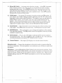
Introduction
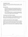
Welcome to the exciting world of CB radio communications! Your UnidenGRANT XL
Citizens Band Mobile Transceiver represents the highest quality communincations
device designed for use in the Citizens Band Radio Service. This powerful unit
operates on any of the 40 AM, 40 LBS, and 40 USB channels authorized by the
Spectrum Management Agency (SMA).
Among its many features, tbe GRANTXLincludes:
.
.
.
.
.
.
.
SSB (single-sideband) operation in addition to standard AM operation
Dual noise reduction circuitry - Noise Blanker and Automatic Noise Limiter
Multi-function Meter - Measures incoming Signal Strength, RP transmitter
output power, and SWR readings
RP Gain Controloperating modes
Provides optimum receiving capability in both AM and SSB
Adjustable Microphone Gain Control
Clarifier Control-
For fme-tuning of SSB signals
Public Address System capability
WARNING
The Citizens Band Radiocommunication Service (CBRS) is under the
jurisdiction of the Australian Spectrum Management Agency (SMA).
Any adjustment or alteration which will change the performance of
the transceiver's original SMAtype acceptance is STRICTLYPROHIBITED. Replacement or Substitution of power or frequency determining components e.g. Crystals, Transistors, ICs, Diodes, etc. with
other than those recommended by UNIDENwill cause violation to the
SMAtype acceptance technical requirement.
Licensing Requirements
Before using your transceiver, you must obtain a Citizens Band Radio License from
the Spectrum Management Agency (SMA). Application forms and brochures relating
to CBRS are available at your nearest SMA office. Mail the completed application
form and the.appropriate fee to the Communications Manager, in the State or
Territory in which the station will be operated.
-1- ..-.-
f
--
------t
.-
-~==
Unpacking Your CB Radio
Carefully check the contents against this list:
.
..
..
.
GRANTXL SSB/AM Mobile Transceiver
Microphone
Microphonehangerkit
Mountingbracketkit
DC power cord
ThisOperatingGuide(readit carefullyandsave)
Ifany items are missing or damaged, contact your place of purchase immediately.
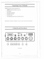
Controls and Functions'
.
~
.
MICGAIII
VOL~a
.
8
:j1j!I!1~~j~~1!1!11~~8
M'" 8
I
-
.]j~
OFF-
I
'.'.'.'.
NBlANL .::::::::::
1RB18IAIITXL
I I I
'.'.'.
BAT
.::::::::::
HI...,.
.:::}~:.
'.:.:::.
~
RXfTX
::i~..'...8
1
7
8
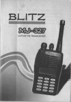
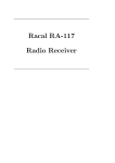
Front Panel
-2- -
-
---- 1-
,~---
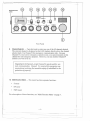
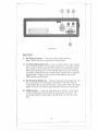
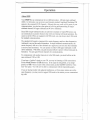
Front Panel
1. MIC(Microphone)GAINControl- Use to adjust the microphone gain during
transmitting. At the maximum setting, you have full talk power during transmitting
while holding the microphone at a comfortable distance. In the PA (Public
Address) mode, this control adjusts the output volume of the PA speaker.
2.
VOl (Volume)Control- Use to turn the power on or off, and to adjust the
receiving audio level.
3.
sa (Squelch)Control- Use to eliminate background noise during the absence of a
signal. Turn the Squelch Control fully counterclockwise, then slowly rotate it
back clockwise until all noise disappears. At this setting, any signal must be
slightly stronger than the background noise to break squelch and be heard.
Rotating the control farther clockwise increases the threshold level below which
weak signals are not heard. At the maximum clockwise setting, only the strong
signals can break squelch and be heard.
4. RFGAINControl- For normal operation, keep the RF Gain Control at the full
.clockwise position.
Turn counterclockwise to reduce incoming signal gain when a
signal is strong enough to saturate your receiver.
5.
SWRCAl Control- Use to calibrate the meter for SWR (standing-wave ratio)
measurements. Make sure the Mode Selector (7) is set to the AMposition. Turn
the Meter Selector (6) to the CAl position. Press and hold the microphone PTT
(push-to-talk) Switch. Turn the SWR CAL Control to adj~st the needle to the ...
position on the SWR meter. Then turn the Meter Selector to the SWRposition to
measure the standing-wave ratio of your antenna system. A lower reading
indicates better antenna matching.
6.
Meter(SlRFCAl SWR)Selector - Use to select the function of the meter. For
normal operation, always set to the SIRF position. The SWR and CAl positions are
for SWR measurement only. (See "Multi-Function Meter" on page 7 for related
information.)
7.
Mode (lSB AMUSB) Selector - Use to select the mode of operation (AM, LSB, or
USB) for both the transmitter and receiver. In SSB (single-side band) mode you
are allowed to transmit 12 watts PEP power. Therefore, you can communicate at
far greater distances than with conventional AM mode operation. Because not all
the CBers are equipped with SSB mode, you can always select AM mode for
nQrmal CB communications. (For more details, see" About SSB" in the Operation
section.)
8.
'-,
CLARIFIER
Control- Use to fme-tunethe SSBreceivingsignals. TheClarifier
Control is provided primarily for SSB mode operations. It can also be used in AM
mode operation to optimize receiving signals.
-3-
-
~
""0=---==-=
.. .
,10
MICROPHONE
JACK
.I .
I
.:::::..
:::::::::::
.:::::::..
.::::::;::.
BRT
HI
e
RXITX
.
CB
PA
MIC GAIN
VOL-+sa
8
16.
.~L
~
.8.
MlN
8
c=
OFF8
RFGA"'-+SWRCAL
LOW ::{?:
DIM
CAL
CLAAFIER
." ~ .8.
tlt~¥
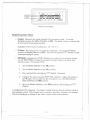
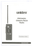
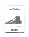
Front Panel
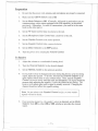
9.
Channel Selector - Turn this knob to select anyone of tbe 40 channels desired
The selected cbannel is displayed on tbe LED readout, directly above the cbannel
selector knob. Use Cbannel9 for emergency communication only. Because
Cbannel 9 is reserved for emergency operation only, you cannot transmit on this
channel for non-emergency purposes. However, you may momtor Cbannel 9
any time you wisb to do so.
Important: All channels, except Channel 9, may be used for normal communication. Channel 9 is reserved for emergency communications involving the immediate safety of individuals or the
protection of property.
10. Multi-function Meter - Tbis meter bas three separate functions:
.
.
.
S-meter
RP meter
SWR meter
For a description of tbese functions, see 'Multi-Function
Meter' on page 7.
-4-
1--
- -,-
--
------
-f
_h_-
-.-
11. NB and ANL Switch
-
Activates
noise reduction
circuitry.
At the ANL (Automatic
Noise Limiter) position, only ANL circuitry is activated in the audio to reduce
background white noise. At the NB/ANL position, this switch activates both the
ANL and NB (Noise Blanker) circuitry in the receiver. The NB circuitry is very
effective for repetitive impulse noise, such as ignition noise. In the OFFposition,
NB and ANL circuits are deactivated.
12. CBlPA
Switch- For normal CB operation, keep this switch at the CBposition. If
you connect a PA (Public Address) speaker (optional) to the PA. SP. Jack on the
rear panel, set the switch to the PA position. This enables you to use the radio as a
public address system. In PA mode, your voice will be heard through the PA
speaker. Also, all incoming signals will be heard through the PA speaker. This
allows you to monitor your channel activity while you are outside your vehicle.
Adjust the PA speaker output volume with the Microphone Gain Control.
- This switch allows you to select the tone of the receiving voice
The LOW position increases bass. The HI position increases treble.
13. HIILOW Switch
in the audio.
14.
-
BRTIDIM
Switch
This switch allows you to change the brightness of the channel
LED and meter lighting. The DIM position lowers the brightness, and may be more
suitable for night driving.
15.
Rxn'XIndicator- This 2-color LED lights to indicate the RX (receive mode) or
TX (transmit mode). The LED is GREENfor RX, and RED for TX. The LED turns
off when pressing the microphone PTT Switch in the PA mode.
16.
Channel
Readout
- This bright LED displays
the selected chamiel number.
Microphone Jack - Connect the microphone to this jack in order to operate either the
receiver or transmitter. If the microphone is not connected, you will hear no audio from
the speaker.
Microphone - Set the Microphone Gain Control to the full clockwise position. Press
and hold the PTT (push-to-talk) Switch, and hold the microphone several inches away
from your mouth. Speak into the microphone clearly in a normal voice. When you are
fmished talking, release the PTT Switch immediately to receive the responding trans-
mission.
-5-
T
f
.~-
<::::;"
Rear Panel
Rear Panel
17. ANT. (Antenna)Connector- Connect the antenna coaxial cable here.
(Note: Antenna and cable with connectors are not included.) -
18. P.A.(Public Address) SpeakerJack- Connect an optional Public Address speaker
here. For the PA speaker, use an 80 speaker with at least a 4-watt rating. Be sure
the PA speaker is directed away from the microphone to avoid acoustic feedback.
When you are operating the PA system with high output level, greater separation
and acoustic isolation between the microphone and PA speaker may be required to
prevent feedback. When this unit is used as a public address system, set the
CB/PA Switch to the PA position.
19. EXT.SP. (External Speaker)Jack- Connect an optional external speaker here. For
the external speaker, use an 80 speaker with at least a 4-watt rating. When an
external speaker plug is connected to this jack, it automatically disables the internal
speaker. This jack is provided for high performance remote receiver monitoring.
20. POWERConnector - Connect the supplied DC power cord here. The DC power
cord has a mating plug attached to ensure the proper polarity connection. This
easy-to-detach feature is useful whenever the unit needs to be stored in a secure
place.
-6r--
-. - -- - - --- -
--
--------
f
,
...
_c=
=-:cc--
r
SWRMETER
RFMETER
S-METER
.
-----.
---
2
SWR
3
CALT
RF
G1
3
5 7 9 +30dB
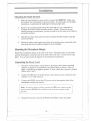
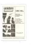
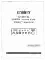
Multi-function Meter
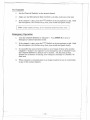
Multi-Function Meter
.
S-meter: Measures the signal strength of the incoming signal. To use the
S-meter, position the Meter Selector at SIRF. The meter swings to indicate the
level of an incoming signal strength.
Examples of the S-meter readings are: S 3, S 5, S 7 . ..
.
.
.
RF Meter: RP output power meter for the transmitter. To use the RF Meter,
position the Meter Selector at SIRF. Press the microphone PTT Switch to read
your transmitting RP power.
SWRMeter: Measures the SWR (standing-wave ratio) of your antenna system.
Use the SWR Meter to adjust the antenna to proper length or to check your
antenna system. To measure SWR:
I.
Set the Mode Selector to the AMposition.
2.
Set the Meter Selector to the CALposition.
3. Press and hold the microphone PTT Switch. (Transmit)
4.
Calibrate the meter using the SWR CAL Control. (Adjust the needle to
the T mark.) Do not talk into the microphone or set the Microphone
Gain Control to the MINposition.
5. Move the Meter Selector to the SWRposition while holding the PTT
Switch.
A reading below 2 is adequate. Any higher reading indicates that the problem exists in
your antenna system. The problem can be caused by humidity, vibration, or corrosion.
Check for breakage or damage to the cable, coaxial cable, and/or antenna.
-7-
~
==
---.
=
Installation
Mounting the Radio Bracket
1. Select an ideal location in your vehicle to mount the GRANTXL. Make sure
the location will not interfere with your driving. In a passenger car, the ideal
installation is underneath the dashboard on the passenger side.
2.
Remove the mounting bracket from the radio and use it as a template for
marking the location of the mounting screws. (Note: If there are screws
already holding the dashboard, you may be able to use the same screw holes to
mount the bracket.)
3.
Drill the necessary holes and secure the mounting bracket in place usmg the
screws provided.
4.
Mount the radio to the bracket only after the wiring has been connected to the
rear panel and the microphone hanger has been installed.
Mounting the Microphone Hanger
Mount the microphone hanger to the side of the radio. Mounting holes are provided
near the microphone connector and on the other side of the unit. Use the screws supplied. You can also mount the hanger on the dashboard, if preferred.
Connecting the Power Cord
1.
Check the vehicle battery connections to detennine which battery tenninal
(positive or negative) is grounded to the engine block or chassis. Most of
today's vehicles use a negative ground. If your vehicle has a negative ground,
follow steps 2 and 3.
2.
Connect the RED wire of the DC power cord to the accessory contact in your
vehicle's +13.8 VDC fuse box.
3. Connectthe BLACKwire of the DC power cord to the negative side of the
automobile (usually the chassis).
Note: In vehicles with a positive ground, the RED wire connects to the
chassis and the BLACKwire connects to the accessory contact in the
fuse box.
4.
Plug the DC power cord into the Power Connector on the rear panel.
-8_.~_.- .
--
----------
f
t
-'__hhO_.__.
Connecting the Antenna
r
Connect the CB antenna plug to the Antenna Connector on the rear panel. (For more
information on antenna installation, please refer to the instruction guide that came with
your antenna.)
CB Antenna Tips
.
.
A vertically polarized quarter-wavelength w~ip antenna provides the most
reliable operation and greatest range. The shorter loaded-type whip antennas are
more attractive and compact than the larger full quarter-wavelength whip.
Although the reduced height decreases possible clearance problems, the shorter
antennas may not provide the same transmitting and receiving range possible
with the longer ones.
A 3-way combination antenna allows you to operate all three bands (AM, FM,
and CB) with one antenna. However, it will provide a shorter transmitting and
receiving range than a standard "single band" antenna designed for CB use only.
You may also notice a higher SWR with this type of antenna.
Connecting an External Speaker (Optional)
Connect an optional external speaker to the External Speaker Jack on the rear of the
transceiver. For the external speaker, use an 8a speaker with at least a 4-watt rating.
When connected, the external speaker automatically disables the internal speaker. The
external speaker will provide high performance remote receiver momtoring.
Connecting a Public Address (PA) Speaker (Optional)
Connect an optional Public Address speaker to the PA. Speaker Jack on the back of
the transceiver. For the PA speaker, use an 8a speaker with at least a4-watt rating. Be
sure the PA speaker is directed away from the microphone to avoid acoustic feedback.
When you are operating the PA system with high output level, greater separation and
isolation between the microphone and PA speaker may be required to prevent feedback.
When this unit is used as a public address system, set the CB/PA Switch to the PA posi-
tion.
-9-
1-
-"==
=---
- -~=
---
Operation
r
About SSB
Your GRANTXL can communicate in two different modes: AM and single-sideband
(SSB). In AM mode, you can receive and transmit standard Amplitude Modulated CB
signals in the assigned 40 CB channels. Although this may work well for most of your
communications, you also have the option of receiving and transmitting 80 singlesideband channels (40 upper sideband and 40 lower sideband).
Since SSB (single-sideband) modes are allowed to transmit 12 watts PEP power, you
can communicate at greater distances than with conventional AM mode operation. Because not all the CBers are equipped with SSB mode, you can always select AM mode
for standard communications.
The standard AM signal is composed of a carrier frequency and two other frequencies
(sidebands) carrying the audio infonnation. In single-sideband communications, the
carrier frequency and one of the sidebands are suppressed, and only the other sideband
is received and transmitted. You can operate on either USB (upper sideband) or LSB
(lower sideband). With SSB, you gain increased effective power without losing any infonnation. You also gain 80 more channels for communications.
To communicate with another transceiver in the SSB mode, you must both be on the
same sideband, USB or LSB.
If you hear a "garbled" signal on your CB, you may be listening to SSB transmission.
Set the Mode Selector to LSB and listen. If the signal is still garbled, or has disappeared, try USB. Once you are in the correct mode, use the Clarifier Control to "finetune" the signal. You will now be able to communicate with the transmitting party.
If you are having trouble with adjacent interference, or if too many stations are on the
same frequency, you may want to suggest SSB mode to the station you are communicat-
ing with.
-10-
rf
=--
=
Preparation
1.
Be sure that the power cord, antenna, and microphone are properly connected.
2.
Make sure the CB/P A Switch is set, to CB.
3.
Set the Mode Selector to AM. (Generally, AM mode is used unless you are
communicating with a station equipped with SSB capability, as described
previously. Remember: In order to communicate, you must be in the same
mode as the other party.)
4.
Set the RF Gain Control fully clockwise to the end.
5.
Set the Microphone Gain Control fully clockwise to the end.
6.
Set the Clarifier Control to the center position.
7.
Set the Squelch Control fully counterclockwise.
8.
Set the Meter Selector to the SIRFposition.
9.
Turn the power on by rotating the Volume Control.
To Receive
1. Adjust the volume to a comfortable listening level.
2.
Turn the Channel Selector to the desired channel.
3.
Set the NB/ANL Switch to the optimum position.
4.
If you prefer to hear no background noise during the absence of an incoming
signal, adjust the squelch. To do this, first turn the Channel Selector to an
open channel where there is only constant noise. Then, turn the Squelch
Control clockwise slowly until the noise just disappears. (No signal should be
present while adjusting the squelch.) Leave the control at this setting. The
receiver will remain quiet until a signal is actually received. Changing the
channel should not affect this squelch setting.
Note: Do not advance the Squelch
signals will not be heard.
5.
Control too far, or some weaker
If an incoming signal (Le., the sender's voice) is distorted, set the Mode
Selector from AMto either LSBor USB,whichever provides the clearest
signal.
-11 - - -'-.
T
J
---=0
To Transmit
1.
Set the Channel Selector to the desired channel.
2.
Make sure the Microphone Gain Control is set fully clockwise to the end.
3.
If the channel is clear, press the PTT Switch on the microphone to talk. Hold
the microphone a few inches away from your mouth and speak clearly.
Note: If the channel is busy, do not transmit until it becomes clear.
Emergency Operation
1. Turn the
Channel
Selector
to Channel 9. Your GRANTXL is now in
Emergency Channel Operation mode.
2.
If the channel is clear, press the PTT Switch on the microphone to talk. Hold
the microphone a few inches away from your mouth and speakclearly.
3.
It is possible that your present location is out of range of those who monitor
Channel 9. If there is no response to your emergency call on Channel 9, turn
the Channel Selector to find an active channel. Ask the party on that
channel for assistance in relaying your emergency message on Channel 9 in
theirarea.
4.
When emergency communication is no longer needed, be sure to switch back
to any of the nonnal channels.
-12-
I'
-
Tt
------
-,c==
-
Care and Maintenance
The GRANTXLis designed to give you years of trouble-free service. There are no userserviceable parts inside, and except for the fuse in the DC power cord, no maintenance
is required.
Note: Do not expose the unit to moisture. Rain, dew, or other liquids may
damage the internal components.
Replacing the Fuse in the DC Power Cord
The main power lead (RED wire) on the DC power cord contains a4-ampere, 3AG fuse
in its holder.
To inspect or replace a blown fuse:
1.
Press the ends of the fuse holder together and twist counterclockwise.
Carefully separate the two halves.
2.
Remove the fuse and inspect. If blown, replace with the same type.
Important:
Using any fuse other than the one specified for your GRANT XL
may void the warranty.
3. Replace the fuse inside the fuse holder, and reassemble the two halves by
pressing the ends together and twisting clockwise.
Servicing Your CB
Technical information, diagrams, and charts are available upon request. It is the user's
responsibility to see that this radio is operating at all items in accordance with the SMA
Citizens Band Radio Service regulations. We highly recommended that you consult a
qualified radiotelephone technician for service and alignment of this radio.
When ordering parts, please specify the cOITectmodel number and serial number of this
radio.
Please refer to the "WARNING" information on page 1of this manual.
-13-
I 1
=---
Troubleshooting
Problem
Unit does not power on.
.
.
.
..
No reception.
.
..
.
.
Poor reception.
\
.
..
No transmission.
.
.
.
Low transmission.
.
Suggestion
Check the ignition key position.
Check all connections to the DC power
cord as well as the fuse inside the holder.
If fuse is out, rep"lacewith a
Make sure the microphone is properly
connected.
Set the CB/PA Switch to CB.
Adjust the squelch and volume.
Make sure that the antenna and its
connections are not broken.
Set the RF Gain Control to the full
clockwise position.
Adjust the squelch and volume.
Check to see that the antenna SWR is 2
or below.
Set the RF Gain Control to the full
clockwise position.
Check the Mode Selector setting. If an
SSB signal is being received, switch to
the proper mode setting (USB or LSB).
Adjustthe ClarifierControl.
Set the CB/PASwitch to CB.
Makesure that the microphoneis
properlyconnected.
Set the Microphone Gain Control to the
full clockwiseposition.
Checkto see that the antennaSWRis 2
or below.
Set the Microphone Gain Control to the
full clockwiseposition.
If you determine that service is necessary, contact your local dealer or return the unit
in its original carton to UNIDEN-Service Department. Ship the item with a brief and
concise description of the problem, your name, address, a telephone number where
you can be reached during working hours and a copy of the original purchase receipt
to the address listed in the Warranty (at the end of this manual).
-
-14-
-
--
----
T-
t
-.=
-
~
-..-
I
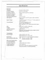
Specifications
General
Channels:
Frequency Range:
Frequency Control:
Frequency Tolerance:
FrequencyStabUky:
Operating Temperature:
Microphone:
In.put Voltage:
Current Drain:
Size:
Weight:
Antenna Connector:
Meter (3.in.l)
40 AM, 40 LSB, 40 USB
26.965 to 27.405 MHz
Phase Locked Loop (PLL) synthesizer
0.005%
0.001%
-300C to+500C
Plug-indynamicwithPIT (push-to-talk)switchand
coiledcord
13.8VDC nominal, 15.9Vmax, 11.7Vmin. (positive or
negative ground)
TX: AM full modulation, 2.2A
SSB 12watts, PEP output, 2A
RX: Squelched,0.25A; with maximum audio output,
0.6A
200mm(W) x 235(D) x 60mm(H)
2.21kg with microphone
UHF, SO-239
muminated; indicates relative power output, received
signal strength, and SWR
Transmitter
Power Output:
Modulation:
IntermodulationDistortion:
SSB Carrier Suppression:
Unwanted Sideband
Frequency Response:
Output Impedance:
Output Indicators:
AM, maximum of 4 watts
SSB, maximum of 12 watts, PEP
High- and low-level, Class B amplitudemodulation
SSB: 3rd order, more than -25 dB
5th order, more than ~35dB
55dB
50dB
AM and SSB; 300 to 2500 Hz
50Q, unbalanced
Meter shows relative RP output power and SWR
Transmit LED glows red when transmitting
-15-
Receiver
Sensitivity:
Selectivity:
Image Rejection:
Adjacent-Cb. Rejection:
IF Frequency:
Automatic Gain Control
(AGC):
Squelcb:
AM and SSB RF Gain
Control:
Clarifier Range:
Noise Blanker:
ANL:
Audio Output Power:
Frequency Response:
Internal Speaker:
External Speaker
(not supplied):
SSB: 0.25 JlVfor 10dB; (S+N)/N at greater than
1/2-wattof audiooutput
AM: 0.5 JlVfor 10dB; (S+N)/N at greater than
1/2-wattof audiooutput
AM: 6dB @ 3kHz,50dB @9kHz
SSB: 6 dB @ 1.1kHz, 60 dB @2.3kHz
More than 65 dB
60 dB AM; 70 dB SSB
AM: 7.8MHz 1stIF, 455kHz 2nd IF
SSB: 7.8 MHz
Less than 10 dB change in audio output for inputs from
10to lOO,OOOJlV
Adjustable; threshold less than 0.25 JlV
40 dB adjustable for AM and SSB
:t 1.5 kHz
RF type, effective on AM and SSB
Switchable
4 watts into 8a
300 to 2500 Hz
8a, round
8a; disables internal speaker when connected
PASystem
Power Output:
External Speaker for PA
(not supplied):
4 watts into external speaker
8a
Specifications shown are typical and subject to change without notice.
-16-
J-
WARRANTY
Uniden GRANT XL CB Radio Australian 2 Year Warranty.
(Accessories are covered for 90 days only).
Note: Please keep your sales docket as it provides evidence of warranty.
WARRANTOR:
Uniden Australia Pty. Ltd. ACN 001 865498
ELEMENTS OF WARRANTY: Uniden warrants to the original retail owner for the duration of
this warranty, its G RANT XL CB Radio (herei nafter referred to as the Product), to be free from
defects in materials and craftsmanship wi th only the limitations or exclusions set out below.
WARRANTY DURATION: This warranty to the original user only shall terminate and be of no
further effect Two (2) Years after the date of original retail sale. This warranty will be deemed
invalid if the product is (A) Damaged or not maintanined as reasonable and necessary, (B)
Modified, altered, or used as part of any conversion kits, subassemblies, or any configurations
not sold by Uniden, (C) improperly installed, (D) Repaired by someone otherthan an authorised
Uniden Repair Agent for a defect or malfunction covered by this warranty, (E) Used in
conjunction with any equipment or parts or as part of a system not manufactured by Uniden,
(F) Installed, programmed or serviced by anyone other than an authorised Uniden Repair
Agent, (G) Where the Serial Number label of the product has been removed or damaged
beyond recognition.
PARTS COVERED: This warramty covers for 2 years; the Transceiver and Microphone only.
All accessories, (Leads, Brackets, Clips, Screws etc.), are covered for 90 days only.
STATEMENT OF REMEDY: In the event that the product does not conform to this warranty
at any time while this warranty is in effect, the warrantor will at its discretion, repair the defect
or replace the product and return it to you without charge for parts or service. THIS
WARRANTY DOES NOT COVER OR PROVIDE FOR THE REIMBURSEMENT OR PAYMENT OF INCIDENTAL OR CONSEQUENTIAL DAMAGES.
WARRANTY CARD: If a warranty card had been included with this product then please fill
it ,n and return it to us withil1114 days of purchase. Your name and the serial number of the
product will then be registel1ed in our database and this will help us to process your claim with
greater speed and efficiency should you require warranty service.
PROCEDURE FOR OBTAINING PERFORMANCE OF WARRANTY: In the event that the
Product does not conform to this warranty, the Product should be shipped or delivered freight
pre-paid, with evidence of original purchase, (eg/a copy of the sales docket), to the warrantor
at:
-
UNIDEN AUSTRALIA PTY L TD SERVICE DIVISION
345 Princes Highway, Rockdale, NSW 2216
Ph (02) 5993100 Fx (02) 599 3278
Customers in other States should ship or deliver the Product
freight pre-paid to their nearest Uniden Authorised Repair Centre.
(Contact Uniden for the nearest Warranty Agent to you).
1j
--,----
unid~n@
(Q1993 Uniden Australia Pty. Limited. All rights reserved.
UTUDO1559BZ
-.k
~~
PrintediDthe PbilippiDeS