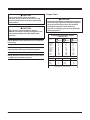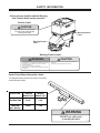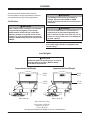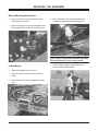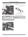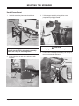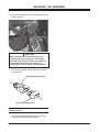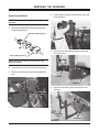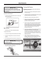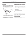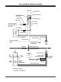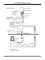
1
August 10, 2005
Lit. No. 94417, Rev. 08
PRO-FLO™ 2
TAILGATE SPREADER
Owner’s Manual
CAUTION
Read this manual before installing or operating
the spreader.
This manual supersedes all editions with an earlier date.
This manual is for WESTERN® PRO-FLO 2 Spreaders with serial numbers
(202650 - )
TABLE OF CONTENTS
PREFACE ................................................................... 1
SAFETY INFORMATION ............................................. 2
Before You Begin .................................................. 2
Torque Chart ......................................................... 3
LOADING .................................................................... 5
Certification .......................................................... 5
Load Weights ....................................................... 5
Approximate Salt Weight ...................................... 5
Approximate Sand Weight .................................... 5
MOUNTING THE SPREADER ..................................... 6
In-Bed Mount ........................................................ 6
Under-Frame Mount .............................................. 8
OPERATING THE SPREADER ................................. 10
Driving and Spreading on Snow and Ice ............... 10
Accessory Circuit ............................................... 10
Adjusting Feed Gate and Deflector ..................... 11
Deflector Effect ................................................... 11
Variable Speed (PWM) Control - New Style ......... 12
Starting and Stopping the Motor .................... 12
Adjusting the Spinner Speed ......................... 12
Blast/Maximum Speed ................................. 12
Diagnostic Indicator Light ............................. 12
Variable Speed (PWM) Control - Old Style .......... 13
Starting and Stopping the Motor .................... 13
Adjusting the Spinner Speed ......................... 13
Blast/Maximum Speed ................................. 13
Spinner Indicator Lights ................................ 13
ON/OFF Control .................................................. 14
Starting and Stopping the Motor .................... 14
Blast/Maximum Speed ................................. 14
August 10, 2005
REMOVING THE SPREADER .................................. 15
In-Bed Mount ...................................................... 15
Under-Frame Mount ............................................ 16
RECEIVER HITCH .................................................... 17
Safety ................................................................. 17
Important Information on Towing .......................... 17
Ball Mounts/Drawbars ......................................... 17
Hitch Balls .......................................................... 17
Trailer Couplers ................................................... 17
Safety Chains ..................................................... 17
Electrical Connections ........................................ 17
Sway Controls .................................................... 17
Other Useful Equipment ...................................... 17
Tire Inflation ........................................................ 18
Equipment and Parts Check ............................... 18
No Passengers in Trailers! .................................. 18
Trailer Loading .................................................... 18
Vehicle ............................................................... 18
Driving ................................................................. 18
Excessive Sway ................................................. 18
Controlling Trailer Sway ...................................... 18
MAINTENANCE ........................................................ 19
Belt Tension ........................................................ 19
Conveyor Belt Tension ........................................ 19
After each use .................................................... 20
At the End of Each Season ................................ 20
Recycle .............................................................. 20
Gear Oil Specification ......................................... 20
4 PIN HARNESS WIRING DIAGRAM ........................ 21
3 PIN HARNESS WIRING DIAGRAM ........................ 22
TROUBLESHOOTING GUIDE ................................... 23
30
ii
Lit. No. 94417/94418, Rev. 08
PREFACE
This manual has been prepared to acquaint you with the
safety information, operation and maintenance of your
new tailgate spreader. Please read this manual carefully
and follow all recommendations. This will help ensure
profitable and trouble-free operation of your spreader.
Keep this manual accessible. It is a handy reference in
case minor service is required.
Lit. No. 94417/94418, Rev. 08
When service is necessary, bring your spreader to your
local outlet. They know your spreader best and are
interested in your complete satisfaction.
NOTE: This spreader is designed to spread snow
and ice control materials only. Do not use it for
purposes other than those specified in this manual.
1
August 10, 2005
SAFETY INFORMATION
WARNING
WARNING
Indicates a potentially hazardous situation that,
if not avoided, could result in death or serious
personal injury.
Overloading could result in an accident or
damage. Do not exceed GVWR or GAWR
ratings as found on the driver-side vehicle door
cornerpost. See Loading Section to determine
maximum volumes of spreading material.
CAUTION
Indicates a situation that, if not avoided, could
result in damage to product or property.
WARNING
Do not install the control for this product in the
deployment path of an air bag. Refer to vehicle
manufacturer’s manual for air bag deployment
area(s).
NOTE: Identifies tips, helpful hints and
maintenance information the owner/operator
should know.
CAUTION
Before You Begin
•
If rear directional, CHMSL light or brake
stoplights are obstructed by the spreader, the
lights shall be relocated, or auxiliary
directional or brake stoplights shall be
installed.
Park the vehicle on a level surface, place shift lever
in PARK or NEUTRAL and set the parking brake.
WARNING
• Driver to keep bystanders minimum of 25 feet
away from operating spreader.
CAUTION
• Before working with the spreader, secure all
loose-fitting clothing and unrestrained hair.
• Do not operate a spreader in need of
maintenance.
• Before operating the spreader, verify all
safety guards are in place.
• Before operating the spreader, reassemble
any parts or hardware removed for cleaning
or adjusting.
• Before servicing the spreader, wait for
conveyor or spinner to stop, then lock out
power.
• Before operating the spreader, remove
materials such as cleaning rags, brushes,
and hand tools from the spreader.
• Do not climb into or ride on spreader.
• Before operating the spreader, read the
owner's manual.
• While operating the spreader, use auxiliary
warning lights, except when prohibited by law.
• Tighten all fasteners according to the Torque
Chart. Refer to Torque Chart for the
recommended torque values.
August 10, 2005
2
Lit. No. 94417/94418, Rev. 08
Torque Chart
CAUTION
Disconnect electric power at spreader
electrical wiring harness connection and tag
out if required before servicing or performing
maintenance.
CAUTION
Read instructions before assembling. Fasteners
should be finger tight until instructed to tighten
according to the torque chart. Use standard
methods and practices when attaching
spreader, including proper personal protective
safety equipment.
CAUTION
Do not leave unused material in hopper.
Material can freeze or solidify, causing unit to not
work properly. Empty and clean hopper after
each use.
Recommended Fastener Torque
Chart (Ft.-Lb.)
NOTE: Maintain proper belt tension for correct belt
functioning.
NOTE: Lubricate grease fittings after each use. Use
a good quality multi-purpose synthetic grease.
NOTE: Airborne noise emission during use is below
70 dB(A) for the spreader operator.
Size
SAE
Grade 2
SAE
Grade 5
1/4-20
5/16-18
3/8-16
3/8-24
7/16-14
1/2-13
9/16-12
5/8-11
3/4-10
7/8-9
1-8
6
11
19
24
30
45
66
93
150
150
220
9
18
31
46
50
75
110
150
250
378
583
SAE
Grade 8
13
28
46
68
75
115
165
225
370
591
893
Metric Grade 8.8 (Ft.-Lb.)
Size
Torque
Size
M6
M8
M 10
7
17
35
M 12
M 14
M 16
Torque
60
95
155
These torque values apply to fasteners
except those noted in the instruction.
Lit. No. 94417/94418, Rev. 08
3
August 10, 2005
SAFETY INFORMATION
Please become familiar with the Warning
and Caution labels on the spreader!
Caution Label
CAUTION
Do not lift spreader by wire channel.
This could cause product damage
and/or personal injury.
Warning/Caution
Label
67272
Warning/Caution
Label
Warning/Caution Label
WARNING
CAUTION
• DO NOT EXCEED GVWR OR GAWR WITH SPREADER AND LOAD.
• TURN SPREADER OFF BEFORE FILLING, ADJUSTING, OR CLEANING.
• BYSTANDERS TO STAY A MINIMUM OF 25 FEET AWAY FROM
OPERATING SPREADER.
• DO NOT CLIMB INTO OR RIDE ON SPREADER.
• KEEP HANDS, FEET, CLOTHING AWAY FROM MOVING CONVEYOR
AND SPINNER.
• READ OWNER'S MANUAL BEFORE OPERATING OR SERVICING
SPREADER.
• EMPTY AND CLEAN SPREADER AFTER EACH USE.
68584
Under-Frame Mount Assembly Labels
The diagram below indicates the location of the safety
and identification labels.
HITCH TYPE
WEIGHT
DISTRIBUTING
WEIGHT
CARRYING
BALL MOUNT
MAX. GROSS
MAX.
TRAILER
TONGUE
WEIGHT (LB.) WEIGHT (LB.)
10,000
1,000
10,000
1,000
67181
WARNING
DO NOT cut, drill, weld
or modify this tube
67182
August 10, 2005
4
Lit. No. 94417/94418, Rev. 08
LOADING
This manual covers vehicles which have been
recommended for carrying the spreader. Please see
your local dealer for proper vehicle applications.
WARNING
Overloading could result in an accident or
damage. Do not exceed GVWR or GAWR
ratings as found on the driver-side vehicle door
cornerpost.
Certification
WARNING
WARNING
New untitled vehicle installation of a spreader
requires National Highway Traffic Safety
Administration altered vehicle certification
labeling. Installer to verify that struck load of
snow or ice control material does not exceed
GVWR or GAWR rating label and complies with
FMVSS.
The use of under-frame or in-bed mounts on
half-ton trucks is restricted to spreading only
salt or calcium chloride. (max. 50 lb. per cu. ft.)
Failure to comply could result in exceeding the
payload capacity.
NOTE: If spreader and ice control material loading
is in doubt, weigh vehicle for compliance with
vehicle ratings.
Load Weights
CAUTION
Read and adhere to manufacturer’s ice control
package labeling including Material Safety
Data Sheet requirements.
Approximate Salt Weight
Approximate Sand Weight
400 lb.
10 ft.³
950 lb.
10 ft.³
156 lb.
3.9 ft.³
371 lb.
3.9 ft.³
Salt = 40 lb./ft.³
Sand = 95 lb./ft.³
Salt = 40 lb./ft.³ (avg.)
Very Course = 35 lb./ft.³
Coarse = 45 lb./ft.³
Fine = 50 lb./ft.³
Plus Approximate Base Unit Weight of 355 Lbs. Including Mount
Lit. No. 94417/94418, Rev. 08
5
August 10, 2005
MOUNTING THE SPREADER
Before Mounting the Spreader
1. Remove the drive cover and remove the small
plastic bag from that area.
4. Secure the front of the mount assembly to the
channel using hold-down bolts. Hand tighten.
2. Remove solid plug on gear case and replace with
elbow and breather contained in the plastic bag.
Hold-down
Bolt
Elbow and
Breather
NOTE: Apply a small amount of grease to the bolt
thread periodically to ensure easy removal.
5. Lift the hopper assembly using a hoist or two
people, and tip slightly forward.
In-Bed Mount
1. Remove the tailgate from the vehicle.
2. Place the mount assembly into the bed of the
vehicle.
3. Slide the assembly forward engaging the locator
studs.
Locator
Studs
August 10, 2005
Mount
Assembly
6
Lit. No. 94417/94418, Rev. 08
MOUNTING THE SPREADER
6. Position the tabs of the hopper assembly over the
top of the mount assembly, and lower.
9. Connect the spreader wiring harness to the vehicle
wiring harness.
Spreader Wiring Harness
Tab
Vehicle Wiring Harness
7. Allow the hopper assembly to lower into position.
10. Verify vehicle stoplights and spreader center high
mounted stoplight are working properly.
CAUTION
NOTE: Grease all electrical connections with
dielectric grease.
Both hold-down pins must be in place and
secured with hairpin cotter pins. The hopper
assembly may become unstable if the pins are
not properly secure while the vehicle is in
motion. Never use a finger to check alignment.
8. Insert hold-down pins and secure with hairpin cotter
pins.
Hairpin Cotter
Pin
Lit. No. 94417/94418, Rev. 08
Hold-down
Pin
7
August 10, 2005
MOUNTING THE SPREADER
Under-Frame Mount
1. Install the secondary frame into the subframe.
3. Lift the hopper assembly using a hoist or two
people, and tip slightly forward.
Secondary
Frame
Subframe
Pockets
Mount Bars
CAUTION
CAUTION
Visually align tabs into the secondary frame.
Visually check Hitch Pin holes before assembly.
Never use a finger to check alignment.
4. Position tabs of the hopper assembly over the top of
the mount assembly, and lower.
2. Insert a hitch pin on each side, and secure with
linchpins.
Tabs
Secondary
Frame
Linchpin
Hitch Pin
August 10, 2005
8
Lit. No. 94417/94418, Rev. 08
MOUNTING THE SPREADER
5. Insert a hold-down pin on each side and secure with
hairpin cotter pin.
Hairpin Cotter
Pin
Hold-down
Pin
CAUTION
Both hold-down pins must be in place and
secured with hairpin cotter pins. The hopper
assembly may become unstable if the pins are
not properly secure while the vehicle is in
motion. Never use a finger to check alignment.
6. Connect the spreader wiring harness to the vehicle
wiring harness.
Spreader Wiring Harness
Vehicle Wiring Harness
NOTE: Grease all electrical connections with
dielectric grease.
7. Verify vehicle stoplights and spreader center high
mounted stoplight are working properly.
Lit. No. 94417/94418, Rev. 08
9
August 10, 2005
OPERATING THE SPREADER
Driving and Spreading on Snow and Ice
Accessory Circuit
CAUTION
The yellow wire in the vehicle harness is provided for
accessory use of 12 Amps or less.
Drinking and then driving or spreading is very
dangerous. Your reflex, perceptions,
attentiveness and judgement can be affected
by even a small amount of alcohol. You can
have a serious or even fatal collision if you
drive after drinking. Please do not drink, then
drive or spread ice control materials.
Follow your vehicle owner’s manual instructions for
driving in snow and ice conditions. Remember when
you drive on snow or ice, your wheels will not get good
traction. You cannot accelerate as quickly, turning is
more difficult and you will need longer braking distance.
Wet and hard packed snow or ice offers the worst tire
traction. It is very easy to lose control. You will have
difficulty accelerating. If you do get moving, you may
have poor steering and difficult braking which can
cause you to slide out of control.
Here are some tips for driving in these conditions.
• Drive defensively.
• Do not drink, then drive or spread snow and ice
control materials.
• Spread or drive only when you have good visibility
for operating a vehicle.
• If you cannot see well due to snow or icy
conditions, you will need to slow down and keep
more space between you and other vehicles.
• Slow down, especially on higher speed roads. Your
headlamps can light up only so much road ahead.
• If you are tired, pull off in a safe place and rest.
• Spreader size reduces driver visibilty to the rear of
the vehicle due to spreader size and location. We
recommend an OSHA compliant backup alarm for
all governed employers.
• Keep your windshield and all glass on your vehicle
clean to see around you.
• Dress properly for the weather. Wear layers of
clothing, as you get warm, you can take off layers.
August 10, 2005
10
Lit. No. 94417/94418, Rev. 08
OPERATING THE SPREADER
Adjusting Feed Gate and Deflector
Spread pattern, pattern width and the amount of material
dispensed are dependent on the spinner speed, feed
gate position, and deflector position.
WARNING
Before making any adjustments to the gate/
deflector settings, turn the spreader off. Wait
for all conveyor or spinner movement to stop.
Feed Gate Adjustment
Move handle up to
increase material flow,
or down to decrease.
Deflector Effect
Driver side
open.
Passenger side
open.
Both sides
open.
Lit. No. 94417/94418, Rev. 08
11
August 10, 2005
OPERATING THE SPREADER
There are two control options. They include the Variable
Speed (PWM) Control and the ON/OFF Control. The
variable speed control was redesigned. Identify old or
new style by the face plates shown for correct operating
instructions.
Blast/Maximum Speed
1. Press and hold the START/BLAST button as long
as maximum speed is needed.
2. Release the button when maximum speed is no
longer needed. The control automatically returns to
the ON position and the speed shown on the speed
dial.
Variable Speed (PWM) Control – New Style
On/Maximum
Speed Button
Diagnostic
Indicator Light
NOTE: When blast is used, the speed dial does not
move to the maximum speed setting, but remains
at the preset speed.
Diagnostic Indicator Light
Off Button (Emergency
stop when required.)
The diagnostic indicator light located to the right of the
START/BLAST button remains dark unless a problem
with the motor or wiring is detected. The light will flash a
number of flashes in a row, pause, then repeat. Count
the flashes to determine the nature of the malfunction
and refer to the diagnostic chart below.
Speed Dial
Starting and Stopping the Motor
# of
Flashes
WARNING
Before starting the spreader, the driver shall
verify all bystanders are a minimum of 25 feet
away from operating spreader.
1. To start the spreader motor, press the START/
BLAST button and release. Both the START/BLAST
and OFF buttons will be backlit when the motor is
running. The spreader will operate at the speed
selected on the speed dial.
2. Press the OFF button to stop the motor. The OFF
button operates as emergency stop when required.
NOTE: The truck ignition must be on to start the
spreader.
Problem
0
2
No Fault
No Power
3
4
No Motor
No Ground
5
Overheated
6
Excess
Current
Possible Causes
–
Battery fuse is blown, or battery
cable is disconnected or faulty.
Motor is disconnected.
Spreader harness ground is
disconnected or faulty.
Motor off due to controller overheat,
possibly due to frozen or jammed
spreader.
Over 35A for more than 1-2 seconds.
(Higher overloads are allowed for
shorter periods of time.)
If additional information is needed, refer to the Troubleshooting section of this manual.
NOTE: If the truck ignition is turned off while the
spreader is running, the motor will stop.
NOTE: Always place the cover on the hopper to
prevent moisture buildup. Do not let the spreader
sit idle with material in the hopper for an extended
period of time. This can cause the material to
compact and reduce or stop the flow of material.
Adjusting the Spinner Speed
The speed setting can be adjusted when the spreader is
either on or off.
1. Turn the speed dial clockwise. The speed will
increase as the number of green LED’s illuminated
on the speed dial increase.
2. Turning the speed dial counterclockwise will
decrease the speed.
August 10, 2005
12
Lit. No. 94417/94418, Rev. 08
OPERATING THE SPREADER
Variable Speed (PWM) Control – Old Style
5
4
The speed setting can be adjusted when the spreader is
either on or off.
6
7
3
1. Turn the speed dial clockwise. The speed will
increase as the numbers on the speed dial
increase.
8
2
START
BLAST
Adjusting the Spinner Speed
9
1
ON
MIN
2. Turning the speed dial counterclockwise will decrease
the speed.
MAX
OFF
SPINNER
Power Switch
(Emergency stop
when required.)
Spinner
Indicator
Lights
SPEED
Blast/Maximum Speed
1. Press and hold the power switch in the START/
BLAST position as long as maximum speed is
needed.
Speed Dial
2. Release the power switch when maximum speed is
no longer needed. The switch automatically returns
to the ON position and the speed shown on the
speed dial.
WARNING
Before starting the spreader, the driver shall
verify all bystanders are a minimum of 25 feet
away from operating spreader.
NOTE: When blast is used, the speed dial does not
move to the maximum speed setting, but remains
at the preset speed.
Starting and Stopping the Motor
1. To start the spreader motor, press the power switch
to the START/BLAST position and release. This is a
momentary position and the power switch will
automatically return to the ON position when
released. The spreader will operate at the speed
selected on the speed dial.
Spinner Indicator Lights
Two lights on the cab control indicate the status of the
motor:
• Left light is red and indicates a fault. When the red
(left) light is on, the power is on and the motor is
not running.
2. Press the power switch to the OFF position to stop
the motor. The power switch will remain in this
position. The power switch OFF position operates
as emergency stop when required.
• Right light is green and indicates power is on.
When the green (right) light is on, there is power to
the control and the motor is running.
NOTE: The truck ignition must be on to start the
spreader.
If there are problems while operating the spreader, refer
to the Troubleshooting section of this manual.
NOTE: If the truck ignition is turned off while the
spreader is running, the motor will stop.
NOTE: Always place the cover on the hopper to
prevent moisture buildup. Do not let the spreader sit
idle with material in the hopper for an extended
period of time. This can cause the material to
compact and reduce or stop the flow of material.
Lit. No. 94417/94418, Rev. 08
13
August 10, 2005
OPERATING THE SPREADER
ON/OFF Control
Blast/Maximum Speed
Spinner Indicator Light
(Illuminated light indicates
power to the motor.)
Move and hold the power switch to the BLAST position
for as long as maximum speed is needed. When
released, the switch will automatically return to the OFF
position and stop the motor.
If there are problems while operating the spreader, refer
to the Troubleshooting section in this manual.
ON
OFF
BLAST
NOTE: Always place the cover on the hopper to
prevent moisture buildup. Do not let the spreader
sit idle with material in the hopper for an extended
period of time. This can cause the material to
compact and reduce or stop the flow of material.
SPINNER
On/Off Control Switch
(Emergency stop when
required.)
Starting and Stopping the Motor
WARNING
Before starting the spreader, the driver shall
verify all bystanders are a minimum of 25 feet
away from operating spreader.
1. Move the power switch to the ON position to start
the motor. Motor will start immediately. The power
switch will remain in this position.
2. Move the power switch the the OFF position to stop
the motor. The power switch will remain in this
position. The power switch OFF position operates
as emergency stop when required.
NOTE: The truck ignition must be on to start the
spreader.
NOTE: If the truck ignition is turned off while the
spreader is running, the motor will stop.
August 10, 2005
14
Lit. No. 94417/94418, Rev. 08
REMOVING THE SPREADER
In-Bed Mount
4. Using a hoist or two people, tip the hopper
assembly forward and lift it off of the mount
assembly.
NOTE: Empty the hopper before removing the
spreader.
1. Disconnect the spreader wiring harness from the
vehicle wiring harness.
Spreader Wiring Harness
5. Loosen and remove the hold-down bolts from the
front of the mount assembly.
Vehicle Wiring Harness
NOTE: Grease the electrical connections using
dielectric grease.
Hold-down
Bolt
2. Install the plug cover over the vehicle harness plug.
3. Remove the hairpin cotter pins and hold-down pins.
Hairpin Cotter
Pin
Hold-down
Pin
6. Remove the mount assembly from the vehicle.
7. Install the tailgate.
Lit. No. 94417/94418, Rev. 08
15
August 10, 2005
REMOVING THE SPREADER
Under-Frame Mount
4. Tip the hopper assembly forward and lift it off of the
mount assembly.
NOTE: Empty the hopper before removing the
spreader.
1. Disconnect the spreader wiring harness from the
vehicle wiring harness.
Spreader Wiring Harness
5. Remove the linchpins and hitch pins retaining the
secondary frame.
Vehicle Wiring Harness
NOTE: Grease the electrical connections using
dielectric grease.
2. Install the plug cover over the vehicle harness plug.
3. Remove the hairpin cotter pins and the hold-down
pins.
Linchpin
Hairpin Cotter
Pin
Hitch Pin
6. Remove the secondary frame assembly from the
subframe.
Hold-down
Pin
Secondary
Frame
Subframe
August 10, 2005
16
Lit. No. 94417/94418, Rev. 08
RECEIVER HITCH
Safety
Hitch Balls
Select by gross trailer weight rating, coupler socket
size, and mounting platform thickness and hole size.
Hole must not exceed threaded shank diameter by
more than 1/16 inch. Use lock washer. Tighten
according to instructions. When tightened, shank must
protrude beyond bottom of nut. Gross trailer weight
rating and ball diameter are marked on balls.
WARNING
• Do not overload any part of your towing
system.
• Do not modify your hitch. Install only on
specified vehicles which are in good
condition.
• This product is designed to tow trailers. Do not
use as cargo carriers, motorcycle carriers,
boat hoists, or coupler alignment devices. Do
not use as a jacking point. Do not attach
anything with or in place of the ball.
Trailer Couplers
The coupler socket should be smooth, clean and lightly
lubricated. Tighten or adjust according to the coupler
manufacturer’s instructions.
• Do not pull multiple trailers. Towing one
trailer behind another may cause severe
instability and loss of control.
Safety Chains
Connect safety chains properly every time you tow.
Cross chains under coupler. Attach securely to the hitch
or tow vehicle so they cannot bounce loose. Leave only
enough slack to permit full turning. Too much slack may
prevent chains from maintaining control if other
connections separate. Do not allow chains to drag on
the road.
Important Information on Towing
Make sure all operators of your equipment read and
understand this information before towing. This
information will help you properly select, use, and
maintain your towing equipment. Learn the capabilities
and limitations of each part.
Electrical Connections
CAUTION
Never exceed the gross trailer weight or
tongue weight of this equipment. Never
exceed the lowest weight rating of any part of
your towing system. See the Label information (rating) area in the Safety section
of this manual.
Make these safety-critical connections every time you
tow, no matter how short the trip. Check operation,
including electric brake manual control, before getting
on the road.
Gross trailer weight is the weight of the trailer plus the
weight of the cargo. Measure gross trailer weight by
putting the fully loaded trailer on a vehicle scale. Tongue
weight is measured by placing the fully loaded trailer on
a level surface with the coupler at normal towing height.
Use a commercial scale to measure the weight at the
coupler.
Sway controls can lessen the effects of sudden
maneuvers, wind gusts, and buffeting caused by other
vehicles. We recommend sway controls for trailers with
large surface areas, such as travel trailers. Adjustable
friction models can help control the sway of travel
trailers with low tongue weight percentages.
Sway Controls
Other Useful Equipment
Ball Mounts/Drawbars
Air springs, air shocks, or helper springs are useful for
some hitch applications. A transmission cooler may be
necessary for heavy towing. Many states require towing
mirrors on both sides
Select these products by their gross trailer weight and
tongue weight ratings. Select hitches and receivers for
specific vehicles. Do not purchase a ball mount or
drawbar which will give more than a four-inch drop or
seven-inch extension as measured from the lower rear
edge of the receiver.
Lit. No. 94417/94418, Rev. 08
17
August 10, 2005
RECEIVER HITCH
Tire Inflation
Controlling Trailer Sway
Check often. Follow tow vehicle and trailer
manufacturer’s recommendations. Improper tire inflation
can cause trailer sway.
Turbulence from another vehicle, a wind gust, or a
downgrade can cause sudden sway along with shift of
the trailer’s load or a trailer tire blowout. If the trailer
sways, it is the driver’s responsibility to assess the
situation and take appropriate action. Below are the
suggestions that may apply when assessing the
situation. If your trailer starts to sway:
Equipment and Parts Check
Check ball, coupler, chains, retaining pins and clips and
all other connections every time you tow. Re-check at
fuel and rest stops.
• reduce your speed gradually.
No Passengers in Trailers!
• hold steering wheel as steady as possible.
Under no circumstances should people be allowed in
trailers while towing.
• and if your trailer has electric brakes, apply the
trailer brakes alone without using the tow vehicle’s
brakes.
Trailer Loading
• do not hit your brake pedal hard unless absolutely
necessary.
Proper loading helps prevent sway. Place heavy objects
on the floor ahead of the axle. Balance the load side to
side and secure it to prevent shifting. Tongue weight
should be 10-15 percent of gross weight for most
trailers. Too low a percentage of tongue weight can
cause sway. Never load the trailer rear-heavy; load the
trailer front heavy.
• do not try to steer out of the sway condition.
Sudden or violent steering can worsen the sway.
• do not speed up or swaying will increase.
• do not continue towing a trailer that tends to sway
or you may lose control.
Vehicle
The spreader operating vehicle shall be maintained
according to the manufacturer’s recommendations.
Driving
The additional weight of a trailer affects acceleration,
braking and handling. Allow extra time for passing,
stopping, and changing lanes. Severe bumps can
damage your towing vehicle, hitch, and trailer. Drive
slowly on rough roads. Stop and make a thorough
inspection if any part of your towing system strikes the
road. Correct any problems before resuming travel.
Excessive Sway
Excessive sway can lead to loss of control. Sway
motion should settle out quickly. Sway tends to
increase on a downgrade. Starting slowly, increase the
speed in gradual steps. If sway occurs, reduce speed
slowly, stop, and adjust your trailer load and equipment.
Repeat until the trailer is stable at highway speed. Do
this whenever your trailer loading changes.
August 10, 2005
18
Lit. No. 94417/94418, Rev. 08
MAINTENANCE
Conveyor Belt Tension
CAUTION
Disconnect electric power at spreader
electrical wiring harness connection and tag
out if required before servicing or performing
maintenance.
To adjust the conveyor belt tension, please adhere to
the following instructions.
1. Loosen the two bearing mounting bolts on each of
the idler bearings.
To keep your spreader running smoothly, observe the
following recommendations:
2. Loosen the locknut on the idler bolt and then tighten
the idler bolt about one full revolution.
• Lubricate grease fittings after each use and at the
end of each season.
3. Repeat this evenly on both sides of the unit.
4. Start the unit to determine if the tension is tight
enough to restart the load. If it is not, repeat the
procedure until the load restarts.
Grease after
each use.
5. Run the load for a few minutes and check the idler
pulley to determine if the belt is running closer to
one side than the other. If belt tracking is centered
and not rubbing the inside of the sills, retighten the
locknuts against the angles and retighten the
bearing mounting bolts.
Use a multi-purpose
synthetic grease.
Belt Tension
6. If the belt is tracking off center, tighten the idler bolt
of the side that the belt is tracking towards.
Sometimes it is necessary to over tighten this side
to make the belt track back to the other side and
then loosen the idler bolt slightly to maintain center
tracking of the belt.
• Maintain proper motor to shaft belt tension.
To adjust belt tension:
1. Loosen the carriage bolt that holds down the idler.
7. After it is determined that the belt is tracking
straight, retighten the locknuts against the angles
and retighten the bearing mounting bolts.
2. Slide the carriage bolt to increase or decrease
tension.
3. After adjusting the idler, tighten the carriage bolt.
CAUTION
Bearing Mounting
Bolt
Locknut
Overtightening the belt may result in damage
to the motor bearing.
4. After tightening the carriage bolt, the belt should
deflect 5/8” between the pulleys.
Idler
Bolt
Motor 5/8"
Adjust
5/8"
Idler
Lit. No. 94417/94418, Rev. 08
Gearbox
(Input Shaft)
19
August 10, 2005
MAINTENANCE
After each use
At the End of Each Season (or extended
storage)
• Wash out hopper and rinse off all external surfaces.
• Wash out hopper and rinse off all external surfaces.
• Wash out the secondary frame slots in the underframe mount to prevent build-up of material.
• Apply dielectric grease on all electrical connections
to prevent corrosion.
• Lubricate all grease fittings with a low temperature
synthetic grease.
• Oil or paint all bare metal surfaces.
Recycle
Slot
When your spreader has performed its useful life, the
majority of its components can be recycled as steel.
Gear oil shall be disposed of according to local
regulations. Balance of parts made of plastic shall be
disposed of in customary manner.
• Apply dielectric grease on all electrical connections
to prevent corrosion at the beginning and end of the
season and after each use.
Gear Oil Specification
• Lubricate all grease fittings with a low temperature
synthetic grease.
August 10, 2005
Use Mobil SHC 632 or Exxon SHP320 or equivalent.
20
Lit. No. 94417/94418, Rev. 08
4 PIN HARNESS WIRING DIAGRAM
Cab Control
White Connector
Two Way Molded
Connector
6 Amp Fuse
Red Connector
14 Ga. Red
8 Ga. Red
8 Ga. Red
14 Ga. Black
_
Battery
+
To Vehicle Ignition
(Accessory Wire or
30 Amp Fuse
Fuse Box)
10 Ga. Red
8 Ga. Black
14 Ga. Yellow
14 Ga. Orange
To Vehicle CHMSL
Signal
Accessory Circuit
(12 AMP Max)
Vehicle
Wiring Harness
Spreader
Wiring Harness
Motor
B
Not
Used
A
Not
Used
CHMSL
Assy
14 Ga. Orange
14 Ga.Yellow
Accessory Circuit
8 Ga. Black
8 Ga. Red
8 Ga.
Red
8 Ga.
Black
14 Ga.
Black
(to CHMSL)
14 Ga.
Black
Split Loom Tubing
Motor Specification
12 Volt DC, .56 kW Motor
Lit. No. 94417/94418, Rev. 08
21
August 10, 2005
3 PIN HARNESS WIRING DIAGRAM
(Early Style Wiring)
Cab Control
White Connector
Two Way Molded
Connector
10 Amp Fuse
Red Connector
14 Ga. Red
8 Ga. Red
8 Ga. Red
14 Ga. Black
_
Battery
+
To Vehicle Ignition
(Accessory Wire or
30 Amp Fuse
Fuse Box)
8 Ga. Red
8 Ga. Black
14 Ga. Red
To Vehicle CHMSL
Signal
Motor
B
A
Vehicle
Wiring Harness
Spreader
Wiring Harness
14 Ga. Gray
CHMSL
Assy
14 Ga. Red
8 Ga. Gray
8 Ga. Blue
Motor Specification
12 Volt DC, .56 kW Motor
August 10, 2005
22
Lit. No. 94417/94418, Rev. 08
TROUBLESHOOTING GUIDE
For control operation and use of diagnostic indicator lights, locate the section for your control style in the Operating
Section of this manual.
PROBLEM
SUGGESTED SOLUTION
1. Check plug connection at cab
control.
2. Battery lead in-line fuse is blown. 2. Change the fuse (4 pin harness6 amp fuse; 3 pin-10 amp) and
inspect for short circuits.
Check power supply for 12V DC.
3. Battery connection is poor.
3a. Check for low battery.
No power to cab control
3b. Clean or replace ring terminal.
(Ignition and control switches ON;
Coat with dielectric grease.
no illumination of indicator light(s).)
4. Battery wiring harness is
4. Repair or replace damaged wires
damaged.
or harness as required.
5. Control circuit breaker is tripped
5. Set the control to the OFF
(ON/OFF Control only).
position. Reset the circuit breaker
and set the control to the ON
position.
1. Replace cab control.
Speed control dial on the Variable 1. Malfunctioning cab control.
2. Reconnect so red matches red
2. Red and white connectors are
Speed (PWM) cab control does
and white matches white.
incorrectly hooked up.
not change motor speed.
1. Reset cab control by turning the
1. Overloaded condition is causing
power OFF. Depress the
over-current protection to activate
START/BLAST switch to resume
(Variable Speed Control only).
operation.
2. Wire harness is damaged or has 2a. Check plug connections at cab
control and spreader.
an open circuit between cab
2b. Check wire connections at
control and spreader.
spreader motor and at vehicle
battery – disconnect motor
leads, turn control on, set cab
Spreader does not operate.
control to maximum on variable
(Indicator light(s) illuminated.)
speed controls and check for
voltage at motor leads.
2c. Repair or replace damaged
wires and connectors
2d. Check the 30 Amp in-line fuse.
Replace if necessary.
3. Spreader motor is not running.
3a. Replace motor if shaft will not
turn.
3b. Remove and inspect both motor
brushes. Replace if worn (Brush
kit 65241).
Unplug the spreader harness
and tag out, if required, before
performing any of the following
repairs.
1. Obstruction is preventing rotation. 1. Clear obstruction.
2. Drive belt is loose or damaged.
2. Adjust tension or replace belt if
worn or damaged.
Spinner does not turn.
(Motor is running.)
3. Motor pulley not secured to
3. Tighten pulley set screw or
motor shaft.
replace pulley if damaged.
4. Spinner pulley is not secured to
4. Replace cap screw and nut if
spinner shaft.
missing or damaged. Replace
pulley if damaged.
5. Spinner shaft bearings are dry or 5. Grease or replace bearings.
seized.
Lit. No. 94417/94418, Rev. 08
POSSIBLE CAUSE
1. Control connector plug is loose.
23
August 10, 2005
TROUBLESHOOTING GUIDE
PROBLEM
Conveyor belt not moving
(Spinner is turning.)
Material in hopper does not flow.
(Conveyor belt and spinner are
moving.)
Spread pattern not optimum
August 10, 2005
POSSIBLE CAUSE
SUGGESTED SOLUTION
Unplug the spreader harness
and tag out, if required, before
performing any of the following
repairs.
1. Obstruction is preventing rotation. 1. Clear obstruction.
2. Drive belt is loose or damaged.
2. Adjust belt tension. Replace belt
if damaged.
3. Pulley is not secured to the
3. Replace cap screw and nut if
spinner shaft.
missing or damaged. Replace
pulley if damaged.
4. Pulley is not secured to the
4. Replace damaged or missing
gearbox shaft.
key. Replace pulley if damaged.
5. Gearbox is damaged.
5. Replace gearbox if output shaft
does not turn when input shaft
turns.
6. Conveyor rollers are not secured 6. Replace missing cap screws and
to the shafts.
nuts. Replace shafts or rollers if
damaged.
7. Conveyor belt is loose or
7. Adjust belt tension. Replace belt
damaged.
if damaged.
8. Conveyor belt is not aligned.
8. Align belt to ride centered on
rollers.
9. Conveyor belt shaft bearings are 9. Grease or replace bearings.
seized or otherwise damaged.
Unplug the spreader harness
and tag out, if required, before
performing any of the following
repairs.
1. Feed gate is closed.
1. Open feed gate fully, then adjust
to desired opening size.
2. Obstruction in hopper.
2. Clear obstruction.
1. Deflector out of adjustment.
1. Unplug the spreader harness
and tag out, if required. Change
deflector adjustment to suit
desired pattern. See Adjusting
Gates and Deflector in the
Operating Section of this manual.
24
Lit. No. 94417/94418, Rev. 08
WESTERN PRODUCTS
7777 NORTH 73RD STREET
P.O. BOX 245038
MILWAUKEE, WISCONSIN 53224-9538
A DIVISION OF DOUGLAS DYNAMICS, L.L.C.
Copyright © 2005 Douglas Dynamics, L.L.C. All rights reserved. This material may not be reproduced or copied, in whole or in part, in any
printed, mechanical, electronic, film or other distribution and storage media, without the written consent of Western Products. Authorization to
photocopy items for internal or personal use by Western Products outlets or spreader owner is granted.
Western Products reserves the right under its product improvement policy to change construction or design details and furnish equipment
when so altered without reference to illustrations or specifications used. Western Products and the vehicle manufacturer may require and/or
recommend optional equipment for spreaders. Do not exceed vehicle ratings with a spreader. Western Products offers a limited warranty for
all spreaders and accessories. See separately printed page for this important information. The following are registered (®) or unregistered (™)
trademarks of Douglas Dynamics, L.L.C.: WESTERN®, PRO-FLO™2.
Printed in U.S.A.
August 10, 2005
Lit. No. 94417, Rev. 08