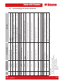
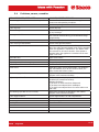
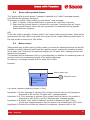
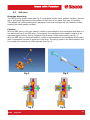
1
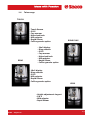
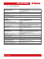
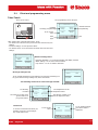
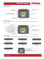
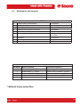
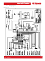
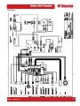
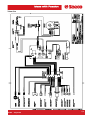
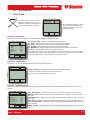
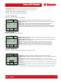
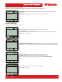
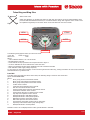
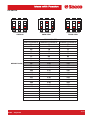
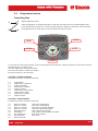
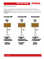
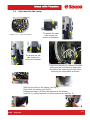
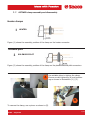
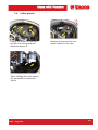
TALEA
TECHNICAL SERVICE
MANUAL
All parts of this document are property of Saeco International Group. All rights reserved.
This document and relative information herein are provided without liability deriving from any errors or omissions. Furthermore,
no part may be reproduced, used or collected with the exception of that authorised in writing or in accordance with a contractual clause.
Issue August 2006
REV.00
TALEA TECHNICAL SERVICE MANUAL (Rev 00 Aug.06): CONTENTS
1.
1.1
1.2
1.3
1.4
Introduction (rev.00)
Documentation required
Tools and equipment required
Safety warnings
Talea range
2. Technical data (rev.00)
2.1 Product technical data
2.2 Internal / external machine components
3. Summarised instructions (rev.00)
3.1 Client and programming menu (rev.00)
3.2 Maintenance and cleaning (rev.00)
4. Diagrams (rev.00)
4.1 Wiring diagram (rev.00)
4.2 Water circuit diagram (rev.00)
5.
5.1
5.2
5.3
5.4
Troubleshooting (rev.00)
Test functions (rev.00)
Diagnostics function (rev.00)
Error messages for Service personnel (rev.00)
Problems, Causes, Remedies (rev.00)
6.
6.1
6.2
6.3
6.4
6.5
6.6
Operating logic (rev.00)
Resetting coffee grounds drawer (rev.00)
Water reserve (rev.00)
Motorized tank (rev.00)
Prima water (rev.00)
SBS valve (rev.00)
Solenoid pilot (rev.00)
7.
7.1
7.2
7.3
7.4
7.5
7.6
7.7
7.8
7.9
7.10
7.11
Component assembly / disassembly (rev.00)
Top cover (rev.00)
Right and left-side cover (rev.00)
Electronics (rev.00)
Gearmotor (rev.00)
Pump (rev.00)
Heater and solenoid pilot unit (rev.00)
Oetiker clamp assembly and disassembly (rev.00)
Coffee grinder (rev.00)
Grinder adjustment/assembly and disassembly (rev.00)
Grinder adjustment during servicing (rev.00)
Motorized drip tray (rev.00)
8. Service schedule (rev.00)
8.1 Routine maintenance Check list (rev.00)
9.
Exploded drawing (rev.00)
TALEA Contents
REV00 - August 06
1/1
SECTION 1
INTRODUCTION
REV.00
TALEA Section 01
REV00 - August 06
1.1
Documentation required
The following technical documentation is required for repairs:
Instruction booklet for specific model.
Technical documentation for specific model (diagrams, exploded drawings).
1.2
Tools and equipment required
As well as the standard equipment, the tools listed below are required.
1 special screwdriver with Torx T10 tip.
1 digital thermometer with full 200°C scale.
This must be suitable for measuring in liquids and on surfaces.
1 set of pliers for Oetiker clamps.
1 pincer.
1 CC -A - Vdc tester.
1.3
Safety warnings
Before starting operations on the machine, consult the relative instruction booklet.
Observe all current standards related to the repair of domestic appliances.
Always disconnect the power plug from the mains before carrying out repairs. Simply turning
off the main switch is not sufficient to prevent electrical discharge.
This domestic appliance is rated with insulation class I.
On completion of repairs, the insulation and dielectric rigidity tests must be performed.
TALEA Section 01
REV00 - August 06
1/2
1.4
Talea range
TOUCH
- Touch Screen
-SBS
- Cup warmer
- Motorized tank
- Milk adapter
- Rapid Steam
- Coffee granule option
RING
RING PLUS
- 24x2 display
- Ring selector
-SBS
- Cup warmer
- Motorized tank
- Milk adapter
- Rapid Steam
- Coffee granule option
- 10x2 display
- Ring selector
-SBS
- Milk adapter
- Rapid Steam
- Coffee granule option
GIRO
- Height adjustment ringnut
-SBS
- Milk adapter
- Rapid Steam
TALEA Section 01
REV00 - August 06
2/2
SECTION 2
TECHNICAL DATA
REV.00
TALEA Section 02
REV00 - August 06
2.1
Product technical data
Power supply and output:
Temperature control:
Safety system:
Coffee heat exchanger output:
Stainless steel
Motorized tank only on
Talea Touch and Ring Plus.
Water level and drip
tray sensor:
Gearmotor:
Cup warmer plate:
Solo Talea Touch and Ring Plus
Pump:
Pressure relief valve:
Water filter:
Coffee grinder:
Solenoid pilot:
Coffee dose control:
Absorption:
Dimensions: l x h x d in mm:
Weight:
Water tank capacity:
Coffee container capacity:
Coffee grounds drawer capacity:
Heatex changer capacity:
Water circuit filling time:
Heating time:
Dispensed drink temperature:
Grinding time:
230 V~, 50/60 Hz, 1300 W.
1 (NTC) variable resistor sensor – transmits the value
to the electronic board.
2 x 175°C manual reset thermostats.
1300 W – to dispense coffee, hot water and steam.
24V stepper motor.
Capacitive sensor
33VC with 2 directions of rotation.
Activated via MENU display.
PTC Type.
Ulka reciprocating piston type with thermal cutout at
100°C,
48 W, 230V, 50 Hz, Type EX5 approx. 13-15 bars.
Opening at approx. 18-20 bars.
In tank.
DC motor with ceramic plate
grinders.
15 VA.
Hall sensor – Pulse control. Dose adjustment can
be set from approx. 7 to 10.5 g.
During heating phase- approx. 5.6 A.
300/375/410
10 kg (average).
1.7 l.
250g coffee granules.
14
Approx. 10 cc.
Approx. 15 sec on first filling cycle.
Approx. 45 sec.
Approx. 73°C - 83°C
Approx. 8-10 sec.
TALEA Section 02
REV00 - August 06
1/4
2.2
Internal / external machine components
Talea Touch
TALEA Section 02
REV00 - August 06
2/4
Talea Ring
(Only for Ring Plus)
(Motorized on Ring Plus
only)
TALEA Section 02
REV00 - August 06
3/4
Internal components
Heater
Pump
Static
eliminator
Turbine
CPU
Card
Power
board
Coffee grinder
Solenoid pilot
Motorized tank
stepper motor
TALEA Section 02
REV00 - August 06
4/4
SECTION 3
BRIEF
INSTRUCTIONS
REV.00
TALEA Section 03
REV00 - August 06
3.1
Client and programming menu
Talea Touch
The programming menu will open.
Press “go to menu”
Main menu
Detailed
beverage programming
To set current
time
Show text
8:30 a
Go to
diagnostics
Next
page
Beverage
settings
Machine
settings
Clock
Maintenance
settings
Next
Machine function
programming
Go
back
Exit
After setting each of the following menus, press:
- “Go back” to be returned to the previous screen and save any new
settings.
- “Previous settings” to reset previous values.
- “Go back to menu” to be returned to the main menu and save new
settings.
Machine settings
Language &
display
Water
settings
Cup warmer
Go back to
menu
Machine settings menu.
- Language & display = to set menu language and display contrast.
- Water settings = to set some water functions.
- Cup warmer = to set cut warmer functions.
Go
back
Beverage settings
Beverage settings menu
Espresso
To set general parameters for the dispense of beverages containing coffee, press the “beverage settings” key in the main menu.
The following can be set for each beverage selected:
Coffee
Long coffee
Go back
to menu
Go
back
Coffee settings
Pre-brewing
of coffee
The amount of coffee to be
ground and use of
pre-ground coffee.
Pre-brewing
Temperature
normal
medium
Aroma
Water quantity
normal
240 / 500
Go back to
menu
The amount of water to be
used in dispensed coffee.
Go
back
Clock settings
Clock menu
To set the current time and timer (for
standby), press the “clock settings”
key on the main menu.
The temperature of the
dispensed coffee.
To set current
time.
Time
Go back to
menu
Stand-by
To set stand-by parameters after coffee is
dispensed.
Go
back
TALEA Section 03
REV00 - August 06
1/3
Talea Ring Plus
To open programming menu.
Use the touch-ring to select the
type of beverage you want.
Strong aroma
Espresso coffee 08:33
To select milk-based
beverage.
MENU
Confirm key.
To select coffee
aroma.
Hot water key.
Beverage settings
To set beverage preparation parameters: press the MENU key and use the touch-ring to select “beverage settings”.
At this point, you can:
Exit the
programming page.
Rotate the touch-ring to vary the
following settings:
- The amount of coffee dispensed
(1 square = approx. 15 ml).
- The amount of water added
(1 square = approx. 15 ml).
- Coffee temperature.
- Pre-brewing of coffee.
1
Beverage settings
Reset default (factory) settings.
MENU
Function depends on the current programming level.
To select coffee
aroma.
To save new settings.
Machine settings
To set general machine settings, press the MENU key, select “machine settings” then use the touch-ring to select:
2.1
Language
Italian
To set menu language.
2.4
Filter alarm.
Enabled
To set machine function with
“Aqua Prima” filter.
2.7
2.2
To set cup warmer function.
2.5
Rinse
Enabled
To set circuit rinsing.
Clock
To set internal clock.
Cup warmer
Disabled
2
MENU
Machine settings
2.3
Beeps
Enabled
To enable beep warnings.
2.6
Water hardness
1
To set water
hardness.
To exit at any time from
“Machine settings”
without saving any changes made,
press the MENU key.
TALEA Section 03
REV00 - August 06
2/3
3.2
Maintenance and cleaning
STEPS
A
B
C
D
E
F
Empty coffee grounds drawer.
Empty drip tray.
Clean water tank.
Clean the coffee granule container.
Clean casing.
Clean and grease the brew group.
H
J
K
Descaling.
Clean drip tray.
Clean coffee circuit.
As instructed.
As necessary.
Once a week.
As necessary.
As necessary
Monthly or every
500 coffees.
As instructed.
Weekly.
Weekly.
Descaling.
Hardness
1
2
3
4
Water hardness
Soft water (up to 7ºdH)
Medium water (7º-14ºdH)
Hard water (15º-21ºdH)
Very hard water (over 21ºdH)
Descaling frequency *
Approx. every 3 months/120 litres
Approx. every 2 months / 90 litres
Approx. every 6 weeks / 60 litres
Approx. every 4 weeks / 30 litres
* Without Prima water filter
TALEA Section 03
REV00 - August
3/3
SECTION 4
DIAGRAMS
REV.00
TALEA Section 04
REV00 - August 06
4.1
Wiring diagram
Talea Touch
TALEA Section 04
REV00 - August 06
1/5
Talea Ring Plus
TALEA Section 04
REV00 - August 06
2/5
Talea Ring
TALEA Section 04
REV00 - August 06
3/5
Talea Giro
TALEA Section 04
REV00 - August 06
4/5
4.2
Talea water circuit
TALEA Section 04
REV00 - August 06
5/5
SECTION 5
TROUBLESHOOTING
REV.00
TALEA Section 05
REV00 - August 06
5.1
Test functions
Talea Touch
3
2
1
4
In the first three seconds after the
appliance is switched on, you can
enter test mode by pressing the keys
in the sequence shown on the left.
t.0
Software version
Next
CPU_V01.04.09
*
*
On entering test mode, the screen
shown in the screenshot opens.
Press the next key to move on to
subsequent levels.
*
Level T1 – brew group
At this level, brew group gearmotor and associated microswitches function is tested.
t.1 - Brewing unit
bu_current (mA)
bu_home
bu_work
bu_present
bu_dregdrawer
bu_door
bu go
home
Next
=
=
=
=
=
=
bu go
work
3
OFF
ON
ON
ON
ON
bu go
stop
-
bu_current (mA) - indicates current absorbed by gearmotor.
bu_home - indicates state of brew group home position microswitch.
bu_work - indicates state of brew group work position microswitch.
bu_present - indicates state of brew group presence microswitch.
bu_dregdraver - indicates state of coffee grounds drawer presence microswitch.
bu_door - indicates state of side door closed microswitch.
By pressing “bu go home” once, the gearmotor moves the brew group to the home position.
By pressing “bu go work” once, the gearmotor moves the brew group to the work position.
By pressing “bu stop” once, the gearmotor stops the brew group.
Level T2 – heating unit
At this level, you can check heater function and the associated ntc sensor.
t.2 - Heating unit
boiler_temp (C°)
Cup
heater
Next
=79.8
Boiler
- boiler_temp (C°) - indicates the temperature of the water heater.
- Pressing “cup heater” once will turn the cup warmer on.
- Pressing “boiler” once will turn the heater on.
*
Level T3 – hydraulic circuit
At this level, you can test pump, solenoid valve, drip tray/water tank level, milk island and water/steam valve status sensor
function.
t.3
Hydraulic circuit
flow_meter (p/s)
driptray_sens
waterlevel_sens
knob_milk
knob_water&steam
knob_closed
milk island present
caraffe present
valve
Next
=
=
=
=
=
=
=
=
0
OFF
ON
OFF
ON
OFF
OFF
OFF
pump
water
TALEA Section 05
REV00 - August 06
*
- flow_meters (p/s) - indicates revolutions per second of the hall sensor in the turbine.
- driptray_sens - indicates the state of the capacitive sensor reading the water level in the
drip tray.
- waterlevel_sens - indicates the state of the capacitive sensor reading the water level in the
water tank.
- knob_milk - indicates the state of the water/steam/milk-island knob in the milk position.
- knob_water&steam - indicates the state of the water/steam/milk-island knob in the water/
steam position.
- knob_closed - indicates the state of the water/steam/milk-island knob in the closed position.
1/17
- Milk island present indicates the state of the milk island present microswitch.
- Caraffe present indicates the state of the milk carafe present microswitch.
- Pressing “valve” once will excite the solenoid valve.
- Pressing “water pump” once will start the pump.
- Pressing “valve” once will activate the solenoid valve.
Level T4 – Grinder unit
At this level, you can test coffee grinder function.
t.4 - Grinder unit
pulses_counter
delay_time (msec)
bean_door
bean_alarm
grinder
Next
=
=
=
=
*
0
0
ON
OFF
- pulse_counter - indicates the number of grinding pulses the grinder performs.
- delay_time (msec) - indicates revolutions per second of the hall sensor in the coffee
grinder.
- bean_door - indicates the state of the coffee bean container lid magnetic sensor.
- bean_alarm - indicates the no coffee beans left alarm during last grinding.
- Holding and pressing “grinder” starts the coffee grinder for at least 200 grinding pulses.
- Pressing “bean test” once starts the coffee grinder to check the no coffee bean alarm.
bean
test
Level T5 – Cup lift
At this level, you can check cup-lift function.
t.5 - Cup lift
Next
upper_switch
lower_switch
key_up
key_down
cup_lift
up
=
=
=
=
cup_lift
down
OFF
OFF
OFF
OFF
*
- upper_switch - indicates the state of the moving tray up position microswitch in the up
position of the moving tray.
- upper_switch - indicates the state of the moving tray lower position microswitch in the
lower position of the moving tray.
- key_up - indicates the state of the capacitive sensor that raises the moving tray.
- key_up - indicates the state of the capacitive sensor that lowers the moving tray.
- Holding and pressing “cup_lift” moves the cup lift up to the uppermost position.
- Holding and pressing “cup_down” moves the cup lift up to the lowermost position.
Level T6 – Grinder dose
At this level, you can test and modify the amount of coffee that is ground.
t.6 - Grinder dose
Mild dose
Medium dose
Strong dose
Mild
Value
up
Next
= 63
= 70
= 77
Medium
Strong
Value
down
TALEA Section 05
REV00 - August 06
Value
test
- Mild dose - indicates the number of grinding pulses to set for a mild coffee.
- Medium dose - indicates the number of grinding pulses to set for a medium-strength coffee.
- Strong dose - indicates the number of grinding pulses to set for a strong coffee.
- Pressing “value up” increases the number of grinding pulses for a medium-strength coffee in
steps of 5.
- Pressing “value down” reduces the number of grinding pulses for a medium-strength coffee
in steps of 5.
- “Mild” and “strong” values are equal to 10% less and 10% more respectively than the average value set.
- Pressing “value test” starts grinding at the selected strength (mild, medium or strong).
2/17
Level T7 – Coffee grounds drawer
At this level, you can modify the current value of the number of coffee grounds (maximum of 13).
t.7 - Dreg counter
Next
Max dreg counter
= 13
Current dreg counter = 9
Value
up
Value
down
- max dreg counter - indicates the maximum number of coffee grounds that the drip tray
can contain.
- current dreg counter - indicates the current number of coffee grounds
*
Level T8 – Steam out
At this level, you can drain the water circuit..
t.8 - Steam out
Next
- boiler_temp (C°) - indicates the temperature of the water heater.
Pressing start will run the procedure.
If the knob state is not in the water/steam/milk-island position, the message shows below
will appear on the display.
Boiler_temp (C°)
Start
*
*
t.8 - Steam out
Next
Boiler_temp (C°)
Open knob to water & steam
- open knob to water & steam - indicates that the knob is not in the water/steam position.
Moving the knob to the water/steam state will start the procedure to drain the water circuit.
Start
*
*
t.8 - Steam out
Next
boiler_temp (C°)
counter
Start
= 105.9
= 7.4
*
*
t.8 - Steam out
boiler_temp (C°)
counter
pass..
Start
- boiler_temp (C°) - indicates the temperature of the water heater.
- counter - indicates the time remaining until the end of the cycle.
When the water heater reaches 100°C, it switches off and the counter starts.
Next
= 105.9
= 7.4
*
- pass - indicates that the procedure has been completed.
Press next to move on.
*
TALEA Section 05
REV00 - August 06
3/17
Talea Ring and Ring Plus
3
1
2
4
When in test mode
Switch the appliance on (double-pole switch on right side) and wait for the CA to finish initializing; then
press and hold the illustrated menu key for 2 seconds until the string “Exit” appears on the screen. Press
the capacitive keypad keys in the order shown on the left within the next two seconds.
Exit
MENU
STEAM
MENU
WATER
AROMA
COFFEE
The following string appears when you enter test mode:
*Test* M0
12345 oo:mm:ss
*Test* MO
oo:mm:ss
SWvx.xx.xx
FFHz
DLv:1.01.10.FT
50HZ
Where:
- *Test* indicates that the C.A. is in test mode.
- M0 indicates the test level.
- 12345 indicate the keys pressed in the sequence shown in figure 1.
- oo:mm:ss indicates the hours and minutes of the CPU clock.
- SWvx.xx.xx indicates the SW version installed in the CPU card microcontroller.
- FFHz indicates actual supply voltage frequency.
To move from one test level to another, use the touch-ring around the coffee key, turning it clockwise to move to the next level
and anticlockwise to go back a level.
Level M1
The state of the microswitch is shown at this level; the following string is shown on the second line:
Inputs 123456789ABCDEFG
Where:
1
Brew group presence microswitch excited.
2
Brew group work position microswitch excited.
3
Brew group home position microswitch excited.
4
Turbine sensor excited.
5
Tank water level capacitive sensor excited.
6
Side door closed microswitch excited.
7
Coffee grounds drawer presence microswitch excited.
8
Coffee bean container sensor excited.
9
Coffee grinder direction of rotation sensor excited.
A
Drip tray level capacitive sensor excited.
B
Water/steam knob in milk-island position.
C
Water/steam knob in water/steam position.
D
Milk-island presence microswitch excited.
E
Milk carafe presence microswitch excited.
F
Cup-lift-down microswitch excited (only on Ring Plus).
F
Cup-lift-up microswitch excited (only on Ring Plus).
H
Water/steam knob in closed position.
Numbers 6 and 7 are not displayed if the coffee grounds drawer is removed.
TALEA Section 05
REV00 - August 06
4/17
Level M2
Gearmotor function is tested at this level. To move the gearmotor, the coffee grounds drawer and side door microswitches must
be excited. The status of the microswitches listed below is shown at the right of the top line on the display:
1
2
3
6
7
Brew group presence microswitch excited.
Brew group work position microswitch excited.
Brew group home position microswitch excited.
Side door closed microswitch excited.
Coffee grounds drawer presence microswitch excited.
Gearmotor status after the aroma key and capacitive keypad menu have been pressed is shown on the second line on the
display:
- Aroma key - the gearmotor brings the group to the home position.
- Menu key - the gearmotor brings the group to the work position.
Power absorbed (mA) by the gearmotor during movement is shown on the right of the second line on the display.
Level M3
Coffee grinder, pump, cup warmer (Ring Plus only) and solenoid valve function are tested at this level. The above are primed by
pressing the following keys:
-
Steam key: coffee grinder.
Water key: pump.
Aroma key: varies grinding aroma.
Menu key: solenoid valve.
Coffee key: coffee grinder pulses.
COFFEE GRINDER TEST:
Coffee bean container sensor must be excited.
When the appropriate key is pressed, the following string appears on the second line of the display:
- Grinder ON 8 GG %%
Where:
-8
indicates that the coffee bean container sensor has been excited.
- GG
indicates the number of rations performed by the coffee grinder.
- %% indicates the ratio between coffee grinder revolutions at 100% and 50% supply.
To set medium aroma pulses, press the coffee key then use the touch-ring to choose aroma pulses. After this, press the coffee
key to save the number of impulses selected. Press the steam key to restore default settings.
By pressing the aroma key, you can vary grinding aroma. The value of the selected aroma is shown on the bottom left of the
display, classified as follows:
1 - mild aroma.
2 - medium aroma.
3 - strong aroma.
PUMP TEST:
By pressing the appropriate key, the following string appears on the display:
- Flowmeter (Imp/s)
GG
Where:
- GG
indicates the number of revolutions performed by the turbine.
SOLENOID VALVE TEST:
By pressing the menu key, the following string appears on the second line of the display:
- Ev Brew On
TALEA Section 05
REV00 - August 06
5/17
Level M4
At this level you can check water heater, relative ntc sensor and cup warmer function.
- When you press the steam key, the ambient temperature (tt.t) is shown on the second line of the display in degrees centigrade.
- When you press the water key, the state of the ntc sensor (open or short) on the water heater
(open o short), or the water heater temperature in degrees centigrade are shown on the second line of the display.
- Pressing the aroma key switches on the water heater (pressing the water key shows the rising temperature) and the string
Heater ON appears on the second line of the display.
- When you press the menu key, the cup warmer is switched on and the string
Cup Heater (Ring Plus only) appears on the second line of the display.
Steamout
Open the knob in the water/steam position to prepare for steamout (draining water heater). Press the coffee key to start, the
water heater will be brought to 120°, at which time the machine emits a sequence of beeps.
WARNING: At the end of this procedure, the machine will automatically switch to English.
Level M5 (Cup lift position) on Ring Plus only.
At this level, you can check cup-lift function.
- Press the aroma key to move the cup-lift down to its lowermost position.
- Press the menu key to raise the cup-lift to its uppermost position.
Level M6 (LCD contrast)
You can change display contrast at this level.
- Press the coffee key to edit display contrast (the percentage value starts blinking).
- You can use the touch-ring to change this value: turn clockwise to increase it, and anticlockwise to decrease it.
- Press the coffee key again to save the value selected.
Level M7 (LCD backlight)
You can change display brightness at this level.
- Press the coffee key to change display brightness
(the percentage value starts blinking).
- You can use the touch-ring to change this value: turn clockwise to increase it, and anticlockwise to decrease it.
- Press the coffee key again to save the value selected.
Level M8 (Self-test)
The machine automatically tests its main functions in the self-test. The brew group must be present and the doors
closed.
On completion of this procedure (which lasts approx. 10 seconds), the outcome will appear on the display.
Pass!! and 2 consecutive beeps if it was successful.
If an error was encountered, 10 beeps will be emitted and a message appears on the display.
Level M9
- Exit.
Press the coffee key to exit test mode and fully restart the appliance.
TALEA Section 05
REV00 - August 06
6/17
TALEA GIRO
Coffee key
Press once to select a coffee.
Press twice to select a double coffee.
Stops coffee from being dispensed when pressed during dispensing.
Water/steam key
To select either water or steam.
Press and hold for 6 seconds to “reset” descaling alarm.
When off, indicates that the machine is ready to release steam.
When on, indicates that the machine is ready to dispense water.
Aroma key
To select either a mild coffee, a medium coffee or a strong coffee.
Middle button
To select length of coffee required.
TALEA Section 05
REV00 - August 06
7/17
Messages/Alarms
Temperature ready LED
Fixed on.
Indicates “Coffee ready” or “Steam ready”.
Temperature ready LED
Slow blinking.
The correct temperature has not been reached.
Water/steam LED
Off
The appliance is in steam mode.
Water/steam LED
Fixed on.
The appliance is in water mode.
Aroma LED
Fixed on.
To set aroma.
General alarms LED
Fixed on.
General alarms LED
Slow blinking.
General alarms LED
Fast blinking.
Fill water tank.
Empty drip tray.
Out of coffee (*)
Door open.
Brew group missing.
Drip tray missing.
Coffee container cover missing.
Milk island or carafe missing.
Prime circuit.
Coffee grounds drawer
LED
Descaling LED
(60 litres)
Coffee grounds drawer
and descaling LEDs
Fixed on.
Indicates that grounds drawer needs emptying.
Slow blinking.
Indicates that descaling (manual) is required.
Blinking alternately.
Max. brew group torque exceeded.
Brew group timeout or microswitch error.
Coffee grinder blocked.
OUT OF SERVICE
Indicates that the appliance is running a “rinse
cycle”.
Temperature ready LED
Light up one after the
Descaling LED
other anticlockwise.
General alarms LED
Coffee grounds drawer
LED
(*) Removing and replacing the coffee bean container will reset the “out of coffee” alarm.
Test mode
To open Test Mode, press
rapid flashing of LEDs
and turn the appliance on at the same time (Power On). Entering Test Mode is indicated by the
(lighting up repeatedly ANTICLOCKWISE one after the other), continuing until
is released.
TALEA Section 05
REV00 - August 06
8/17
POSITION
POTENTIOMETER
ACTION
CHECK
Solenoid pilot
Press
Coffee grinder
Press
Set aroma.
(default: 90-100-110 pulses).
Press
Valve open.
Brew group missing microswitch
Drawer missing microswitch
Door open microswitch.
Coffee container cover microswitch
Carafe present microswitch
(with valve closed).
Turbine sensor
(during pump function)
Water tank sensor
Coffee grounds drawer
lights up and stays on.
blinks slowly.
blinks slowly.
blinks slowly.
blinks slowly.
lights up and stays on.
blinks (turb. freq.)
lights up and stays on.
lights up and stays on.
POSITION
POTENTIOMETER
ACTION
CHECK
Coffee heater.
Press
Press
Press
Unit down microswitch.
+ Steam key pressed.
Valve open.
Brew group missing microswitch
Drawer missing microswitch
Door open microswitch.
Coffee container cover microswitch
Carafe present microswitch
(with valve closed).
Turbine sensor
(during pump function)
Water tank sensor
Coffee grounds drawer
Unit down.
Set aroma.
(default: 90-100-110 pulses).
blinks quickly.
lights up and stays on.
blinks slowly.
blinks slowly.
blinks slowly.
blinks slowly.
lights up and stays on.
blinks (turb. freq.)
lights up and stays on.
lights up and stays on.
TALEA Section 05
REV00 - August 06
9/17
POSITION
POTENTIOMETER
ACTION
CHECK
Pump
Press
Unit up.
Press
Set aroma.
(default: 90-100-110 pulses).
Press
Unit microswitch up.
+ Steam key pressed.
Valve open.
blinks quickly.
lights up and stays on.
Brew group missing microswitch
blinks slowly.
Drawer missing microswitch
blinks slowly.
Door open microswitch.
Coffee container cover microswitch
blinks slowly.
blinks slowly.
Carafe present microswitch
(with valve closed).
lights up and stays on.
Turbine sensor
(during pump function)
blinks (turb. freq.)
Water tank sensor
lights up and stays on.
Coffee grounds drawer
lights up and stays on.
Special functions mode
The “Special Functions” mode allows you to:
1) Activate the steamout procedure.
2) Identify which microswitch is responsible for the
To enter Special Functions Mode, press
“General Alarms” LED lighting up.
and switch on the appliance (Power On) at the same time. Entering Special
Functions Mode is indicated by the rapid flashing of LEDs
after the other), continuing until
(lighting up repeatedly CLOCKWISE one
is released.
TALEA Section 05
REV00 - August 06
10/17
POSITION
POTENTIOMETER
ACTION
Open valve and
press
Press
Brew group missing
microswitch
Drawer missing
microswitch
Door open
microswitch.
Coffee container
cover microswitch
POSITION
POTENTIOMETER
CHECK
Steamout procedure.
While the procedure is underway (for a total of 30 seconds), the following
LEDs light up alternately one after the other in a clockwise direction
light up and each time the key is pressed, the number of
pulses for AVERAGE AROMA is reduced by 5 pulses to a minimum of 60
pulses.
lights up and stays on.
lights up and stays on.
lights up and stays on.
lights up and stays on.
ACTION
No action!
Press
Press
Brew group missing
microswitch
Drawer missing
microswitch
Door open
microswitch.
Coffee container
cover microswitch
POSITION
POTENTIOMETER
CHECK
No action!
lights up and stays on.
lights up and stays on.
lights up and stays on.
lights up and stays on.
ACTION
CHECK
Press
No action!
Press
light up and each time the key is pressed, the number of
pulses for AVERAGE AROMA is increased by 5 pulses up to a maximum of
150 pulses.
Brew group missing
microswitch
Drawer missing
microswitch
Door open
microswitch.
Coffee container
cover microswitch
lights up and stays on.
lights up and stays on.
lights up and stays on.
lights up and stays on.
TALEA Section 05
REV00 - August 06
11/17
DIP SWITCH
ON
1
ON
2
3
CONFIGURATION
ODEA GO
DEFAULT DATA
MILD STRENGTH
54
59
63
68
72
77
81
86
90
95
99
104
108
113
117
122
126
131
135
1
ON
2
3
CONFIGURATION
ODEA GIRO
AROMA PULSES
MEDIUM STRENGTH
60
65
70
75
80
85
90
95
100
105
110
115
120
125
130
135
140
145
150
1
2
3
CONFIGURATION
TALEA GIRO
STRONG STRENGTH
66
71
77
82
88
93
99
104
110
115
121
126
132
137
143
148
154
159
165
TALEA Section 05
REV00 - August 06
12/17
5.2
Diagnostics function
Talea Ring Plus
2
1
4
3
When in diagnostics mode
Switch the appliance on (double-pole switch on right side) and wait for the CA to finish initializing; then
press and hold the menu key for 2 seconds until the string “Exit” appears on the screen. Press the capacitive keypad keys in the order shown on the left within the next two seconds.
Exit
MENU
STEAM
MENU
WATER
AROMA
COFFEE
To move from one test level to another, use the touch-ring around the coffee key, turning it clockwise to move to the next level
and anticlockwise to go back a level.
Press the coffee key to open the sub-menus.
Press the coffee again to confirm any changes.
Press the menu key to exit sub-menus.
Level M1 : Product Counters
The following counters are shown at this level:
1.1
1.2
1.3
1.4
1.5
1.6
1.7
1.8
1.9
Total
Total
Total
Total
Total
Total
Total
Total
Total
Products
number of espressos.
ml of espresso
number of coffees.
ml of coffee.
number of long coffees.
ml of long coffee.
number of waters.
ml of water.
Level M2 : Total Counters
The following counters are shown at this level:
2.1
2.2
2.3
2.4
2.5
2.6
2.7
2.8
2.9
Water S.L.Descale
Water S. 1 Descale
Water S. 2 Descale
Water S. 3 Descale
Water Since Prod.
Descaling N°
B.U. Cleanings N°
Water Filters N°
E2prom writes N°
water since last descaling.
water since last descaling.
water since second last descaling.
water since third last descaling.
water used since production.
total number of times appliance descaled.
times group cleaned.
filters used.
TALEA Section 05
REV00 - August 06
13/17
Level M3 : Error Log
3.1 Errors List
The following are shown at this level:
-)
-)
The last 20 errors involving the CA
The date the error occurred.
The error map is shown below:
Code
Brief description
Description
COFFEE GRINDER ERRORS
Coffee grinder blocked.
The coffee grinder won’t turn: there may be something obstructing
the grinders or beverage signal has not been read correctly by the Hall
probe in the coffee grinder.
01
BREW GROUP ERRORS
03
04
16
TORQUE_FAULT_FWD
Maximum force exceeded in forward movement to dispense position
(second attempt).
TIMEOUT_FWD
Maximum time exceeded to reach dispense position.
TIMEOUT_FWD_DOWN
Maximum time exceeded to clear home position microswitch.
HOME_WHILE_WORKING
Home position microswitch activated while moving to work position.
TORQUE_FAULT_RWD
Maximum force exceeded returning to home position.
TIMEOUT_RWD
Maximum time exceeded returning to rest position.
WORK_WHILE_HOMING
Work position microswitch activated while moving to home position.
HOME_AND_WORK_PRESSED
Both the work and home microswitches are activated at the same time.
WATER CIRCUIT ERRORS
05
Water circuit blocked.
This can happen for a variety of reasons ...(trips when water not flowing in turbine).
TEMPERATURE CONTROL ERRORS
10
SENSOR1_SHORT
Coffee heater sensor shorted.
11
14
SENSOR1_OPEN
Coffee heater sensor in open circuit.
TEMPERATURE_BO_TOO_HIGH
Coffee heater temperature too high.
TEMPERATURE_BO_OUT_CONTROL
Coffee heater temperature out of control (not responding to stimuli:
e.g. heater on but temperature not rising).
15
GENERAL ERRORS
19
No zero crossing.
No zero crossing on card, could be caused by power card.
3.2 Clear all?
pressing YES will delete all errors at level 3.1.
TALEA Section 05
REV00 - August 06
14/17
Level M4 : Products Settings
The parameters for each different beverage are shown at this level; these parameters can be modified by opening each item
using the coffee key and selecting with the touch-ring.
4.1 Espresso Settings:
4.1.1 Product Qty. (imp.)
4.1.2 Aroma
4.1.3 Prebrewing
4.1.4 Temperature
Number of water pulses.
Displays coffee grinder pulses in 60-150 pulse range.
0: pre-ground (0 pulses); 1: mild (- 10% medium); 2: medium; 3: strong (+10% medium).
Prebrewing 1: enabled; 0: disabled; 2: long.
Shows temperature in °C. Low (-3°C average), average, high (+3°C average).
4.2 Coffee Settings:
4.2.1 Product Qty. (imp.)
4.2.2 Aroma
4.2.3 Prebrewing
4.2.4 Temperature in °C
Number of water pulses.
0: pre-ground; 1: mild; 2: medium; 3: strong.
1: enabled; 0: disabled; 2: long.
4.3 Long Coffee Settings:
4.3.1 Product Qty. (imp.)
4.3.2 Aroma
4.3.3 Prebrewing
4.3.4 Temperature in °C
Number of water pulses.
0: pre-ground; 1: mild; 2: medium; 3: strong.
1: enabled; 0: disabled; 2: long.
Level M5 : System Settings
System parameter values are shown at this level:
5.1
5.2
5.3
5.4
5.5
5.6
5.7
5.8
5.9
5.10
5.11
5.12
5.13
5.14
5.15
5.16
5.17
SW Version
Boot Version
Aroma Setup (imp.)
Temp. Standby
Cup. temp.
Standby temp.
Flowrate (L/h)
Language
Water Hardness
Lcd Backlight
Lcd contrast
Grounds Limit
Grounds Left
Grounds Warning
W.Filter C. Date
Service Date
Production Date
Number of pulses set for medium aroma.
From 50° to 80°C.
Standby time can be varied in 15 minute intervals.
Water flowrate.
Display brightness.
Display contrast.
Stop coffee grounds.
Coffee grounds counter.
Empty coffee grounds.
Date Aqua Prima filter was installed.
(to be added after servicing).
TALEA Section 05
REV00 - August 06
15/17
REV00 - August 06
All models
Primea
All models
All models
All models
Primea
Primea
Primea
All models
Primea
All models
All models
All models
All models
All models
All models
01
02
03
04
05
06
08
09
10-11
12-13
14-15
16
17
18
19
20
Heater temperatures out of control.
Steam heater sensors shorted or in open circuit.
Cup lift error.
No zero crossing.
Clock error.
Memory error.
The two stroke end position microswitches are activated at the same
time.
No zero crossing on card, could be caused by power card.
Memory defect or impossible to set.
Impossible to read or write to e2prom.
Both microswitches activated on brew group. The work and home microswitches have both been activated.
Various temperature errors.
Various sensor errors.
Water heater sensors shorted or in open circuit.
Communication interrupted for more than 2 seconds.
Communication error between CPU and
POWER.
Various sensor errors.
The cappuccinatore has failed to reset because it can’t excite microswitch.
No water in turbine.
Multivalve blocked.
Microswitch not released in down position after 3”, torque error trying to
move up, ascent time out exceeded.
The coffee grinder is blocked (grinders blocked or sensor not reading
properly).
The coffee grinder is blocked (grinders blocked or sensor not reading
properly).
Microswitch not released in up position after 3”, torque error trying to
move down, descent time out exceeded.
Description
Cappuccinatore valve blocked.
Water circuit blocked.
Multivalve error.
Brew group blocked in home position.
Brew group blocked in work position.
Coffee grinder 2 blocked.
Coffee grinder 1 blocked.
Brief description
A) The last 20 errors to be recorded.
B) Total number of errors (not all models).
•
Since production (total).
•
Since last service (partial).
•
Current.
On models in the new Primea, Talea and Odea ranges, errors recorded can be viewed on the display (during diagnosis) or on a PC (with programmer). The following are saved:
Applicable models:
Primea-Odea-Talea
Code
5.3
Error messages for service personnel
PRIMEA Section 05
16/17
5.4
Problems, causes, remedies
HELP MESSAGES DISPLAYED
HOW TO RESET MESSAGE
Turn the appliance off and on to solve the problem.
Switch off and after 30 sec. turn on the appliance to
restore normal operating conditions.
Call the Service Centre.
Problem requiring assistance of Service Centre.
Insert drip tray.
Insert drip tray.
Close coffee granule container cover.
Close the coffee granule container to enable delivery
of any beverage.
Insert ground coffee.
This message guides the user when this type of coffee has been selected during personalised beverage
programming.
Insert brew group.
Insert brew groupin seat.
Insert coffee grounds drawer.
Insert coffee grounds drawer.
Empty coffee grounds drawer.
Remove coffee grounds drawer and empty.
N.B: The coffee grounds drawer must only be emptied
when the appliance is switched on. The drawer must
be removed for at least 5 seconds. If the drawer is
emptied when the appliance is switched off the message is not reset.
Close side door
Close service door.
Fill water tank.
Fill tank.
Empty drip tray below brew group.
Empty drip tray.
Insert milk container.
Insert container in milk compartment.
Prime circuit.
Start filling water circuit automatically. The appliance
will automatically try to fill the circuit 5 times; if it
fails, contact the Service Centre.
The descaling cycle did not run correctly.
Repeat the operation as described in the relative
chapter in the instruction booklet.
Replace Aqua Prima filter.
This message is only displayed if the filter control is
enabled (see instruction booklet).
Replace the filterif:
1) 60 litres of water have been dispensed.
2) 90 days have elapsed since installation.
3) 20 days have elapsed since the coffee maker was
last used.
The cleaning cycle did not run correctly.
Repeat the operation as described in the relative
chapter in the instruction booklet.
Insert cappuccinatore.
Insert cappuccinatore in milk compartment.
Rinse milk container.
Clean container after use.
Descale appliance.
Run descaling cycle
Standby.
Press “ start”.
PRIMEA Section 05
REV00 - August 06
17/17
SECTION 6
OPERATING
LOGIC
REV.00
TALEA Section 06
REV00 - August 06
6.1
Reset coffee grounds drawer.
The “empty coffee grounds drawer” message is signalled by a “coffee” beverages counter
controlled by the appliance electronics.
The counter is cleared “empty coffee grounds drawer” reset message:
1. After 13 coffees, if the grounds drawer is removed for more than 5 seconds.
2. Each time the grounds drawer is removed for more than 5 seconds when an “empty
coffee grounds drawer” alarm has been generated (it is assumed that the grounds
drawer has been emptied).
N.B:
If the 12th coffee is actually a “double coffee”, the “empty coffee grounds drawer” alarm will be
generated at the 14th coffee. As a result, the counter for the “empty coffee grounds drawer” in
this case would be reset at the 14th coffee.
6.2
Water reserve
Talea models have a fixed reserve (turbine pulses) to ensure the selected beverage can be fully
(partially or totally) dispensed each time the capacitive sensor registers the presence of water
in the water tank. Otherwise, the appliance displays the “fill water tank” message and will not
dispense the beverage.
The beverage will be dispensed in full or in part depending on whether the remaining reserve is
enough to cover the programmed length of the selected beverage.
On selection, a message requests that the water tank is filled.
Example:
Starting water level
10 cc
actual 90 cc level
not configurable
via SW
Capacitive sensor
e.g: sensor registers presence of water (+10cc).
Hypothesis 1) A 60cc beverage is selected, 50cc is taken from the reserve, the beverage is
dispensed in full, and the “fill water tank” message appears.
Hypothesis 2) A 110cc beverage is selected, 90cc is taken from the reserve, the product is
dispensed in part (100cc), and the “fill water tank” message appears.
Hypothesis 3) A double 110cc coffee is selected; the first is dispensed in part (100cc),
the fill tank message appears, then the second one is dispensed in full (110cc).
Hypothesis 4) Double 40cc coffees are selected; the appliance dispenses both in full.
TALEA Section 06
REV00 - August 06
1/6
6.3
Motorized tank
The movement of the motorized tank is mechanical by means of a stepper motor (1) in 24V
DC, controlled by two capacitive pushbuttons (2) located at the front of the tank.
The two microswitches (3) are for the limit switch, and operation can be checked in test mode
(see section 5.1).
1
3
2
2
3
3
3
TALEA Section 06
REV00 - August 06
2/6
6.4
Aqua Prima
Operating logic with “AQUA PRIMA” filter.
When use of the “aqua prima” filter is selected on the user menu or via the control panel, the
system water count logic is as follows:
If the “aqua prima” function is enabled the electronics perform a pulse count of the turbine,
recording one pulse every 2 revolutions.
If the “aqua prima” function is disabled, the electronics perform a pulse count of the turbine,
recording one pulse every revolution.
The graph in the figure below illustrates this function:
Aqua Prima
on
Aqua Prima
off
Turbine revs
360°
1 rev
360°
1 rev
360°
1 rev
360°
1 rev
= 1 pulse
TALEA Section 06
REV00 - August 06
3/6
6.5
SBS Valve
Beverage dispensing
The SBS brewing system valve (see Fig. 2) controllable via the knob, enables variation (increasing or decreasing according to the position of the knob) of the water flow rate for brewing.
This adjusts the coffee brewing time (extraction time) and consequently the intensity of taste,
keeping the cream quality constant.
Function
With the SBS valve in the open position, coffee is accumulated in the membrane valve due to a
low back-pressure of the SBS valve. Consequently the membrane valve needle remains in the
maximum open position, due to resistance of the spring. Coffee exits quickly (see fig. 3).
With the SBS valve in the closed position, coffee is accumulated on the membrane of the valve
with a consequent increase in pressure in the valve. The spring yields to the back-pressure and
the needle then reduces the coffee passage (see Fig. 4).
Fig.1
Fig.3
TALEA Section 06
REV00 - August 06
Fig.2
Fig.4
4/6
SBS valve operation check
To ensure correct operation of the valve SBS a long coffee should be made, and during
preparation of the latter, check the difference in dispensing speed between the maximum and
minimum positions.
The difference in dispensing speed is approx. 2.5 times greater (and therefore VERY
obvious!!).
TALEA Section 06
REV00 - August 06
5/6
6.6
Solenoid pilot
Needle
Drain
Brew group valve
(3 - 5 bars)
Brew
group
drain valve
Solenoid pilot function:
1.
Brew group drain: before the group is lowered, the solenoid pilot opens briefly creating a depression
that in turn opens the valve in the opposite direction from dispensing, allowing any
water left in the group to be drained and keeping the pad dry.
2.
Coffee ready after steam: when a coffee or water are selected, the solenoid pilot opens the drain valve
to lower pressure in the heater.
3.
Prime heater: after a period in standby or when the appliance has not been used for an extended period
(1st coffee), the pump loads briefly during grinding to get rid of any water between the
heater pin and heater, and to pre-heat the elements.
4.
Fill circuit: the solenoid pilot discharges and recharges automatically. The discharge occurs via the drain
pipe and not via the valve.
5.
Relief valve: the solenoid pilot also serves as a relief valve (not present on pump), opening in the event
of pressure in excess of 16-19 bars.
6.
Lower pressure: pressure is lowered by the circuit being discharged for 10 seconds after water or steam
have been dispensed (see variables A and B).
A)
Configuration with dual-sensor valve card (water/steam position sensor + Milk Island position sensor):
After water has been dispensed - > the solenoid pilot opens to the discharge side as soon as the sensor is
disengaged.
Immediately after steam has been dispensed - > the solenoid pilot opens to the discharge side as soon as
the sensor is disengaged.
Water dispensed after steam has been dispensed -> the solenoid pilot opens to the discharge side as soon
as the sensor is disengaged.
- After each beverage has been dispensed -> the solenoid pilot opens to the discharge side.
- Each time the appliance is switched on and the temperature is reached -> the solenoid pilot opens to the
discharge side.
- When the temperature is reached -> the solenoid pilot opens to the discharge side.
B)
Configuration with three-sensor valve card (water/steam sensor + closed position sensor +
milk island position sensor):
In addition to the functions described in configuration A, the following also occur:
Each time the closed position central sensor is disengaged -> always open the solenoid pilot towards the
discharge side.
TALEA Section 06
REV00 - August 06
6/6
6.7
Milk Island
Electrical connection to appliance.
Button to
attach/release
Milk Island
from appliance.
Water pipe connected to
appliance for steam inlet.
Steam
outfeed
Anchor pin
between Milk Island
and appliance.
Carafe
present
LED
Unscrew bolts
indicated to
dissassemble.
1
5
2
1 Cappucinatore cover.
3
2 Cappucinatore valve cover.
4
3 Vernay valve.
4
6
7
Cappucinatore valve
cover insert.
5 Cappucinatore body.
6 Carafe handle.
8
7 Carafe milk suction pipe.
8 Carafe steamout pipe.
9
9 Top part carafe.
SECTION 7
COMPONENT
ASSEMBLY
AND DISASSEMBLY
REV.00
TALEA Section 07
REV00 - August 06
7.1
Top cover
Remove the coffee container cover,
loosen the indicated screws and
pull off the steam knob.
To remove the coffee brew unit cover, follow
the steps in a clockwise direction, remove the
SBS knob, loosen the middle screw, take off
the knob support, and loosen the indicated
screws.
Pull out coffee container cover
sensor.
Raise the cover from the back and then pull
on the front part as shown in the photo.
Unfasten the PTC connection from the cup warmer.
TALEA Section 07
REV00 - August 06
1/11
7.2
Right and left side casing
Loosen the screw as shown.
To remove the right
side, loosen the
screws as indicated.
To remove the left
side, loosen the
screws as indicated.
To take the left-side off, release the small
clamp and pull out the wire mesh pipe
connecting the steam pipe to the valve,
removing the metal band as shown.
1
2
Split the two sides of the casing (see Fig..1).
Press from the bottom (see Fig.2).
Release and take it off from the side and at the bottom
(see Fig. 3), pulling towards you at the same time (see Fig. 4).
3
TALEA Section 07
REV00 - August 06
4
2/11
7.3
Electronics
CPU card
2
1
3
Fig.1 Loosen the screws as indicated and turn the front piece upwards to get to the card.
Fig.2 Take off the small clamp.
Fig.3 Disconnect all connectors and loosen the screws as indicated.
Power board
Remove the small clamps, disconnect all connectors and loosen the screws indicated.
TALEA Section 07
REV00 - August 06
3/11
7.4
Gearmotor
A
B
Remove the safety guard (A)
by loosening the screws as
indicated.
Loosen the two screws indicated
and remove the heater pin. When
refitting it, be careful with the
two oil-rings shown in the smaller
picture.
The following are fitted inside the compartment protected by the guard:
- Electric motor (A) with gears (B) and (C) for
transmission and timing of the brew group.
- The drip tray presence reed switch
sensor (D).
- Brew group presence microswitch (E).
- Microswitch (F) which intercepts the rest
phase of the brew group.
- Microswitch (G) which intercepts the dispense phase of the brew group.
Withdraw the gear (C) that meshes with the motor
transmission shaft.
Withdraw the large gear (B).
Pull out the motor (A) complete with transmission
shaft (H).
E
F
Disassemble the protection plate (B) by
loosening the screws as
indicated.
B
G
C
A
D
B
P
L
Install the motor and transmission shaft,
inserting the guides (L) in the relative seat.
Insert the gear (B), taking care
that the arrow stamped on the
element is within the opening that
contains pin (P).
TALEA Section 07
REV00 - August 06
4/11
7.5
Pump
1 2
Take the pump out from the rubber support guides.
Pull out the adapter.
TALEA Section 07
REV00 - August 06
Withdraw the faston connectors as indicated.
Take off the oetiker
clamp as indicated and
pull out the reinforced
flexible hose.
5/11
7.6
Heater and solenoid pilot unit
Loosen the screws as indicated.
A
B
C
Loosen the screws on the
relief valve assembly.
Take off the oetiker clamp A,
pull out the reinforced flexible hose, loosen screw B and
withdraw the drain pipe C
from the solenoid pilot.
A
Heater
Unhook the teeth anchoring to the body and lift the
heater and solenoid pilot.
Solenoid pilot.
TALEA Section 07
REV00 - August 06
6/11
7. 7
OETIKER clamp assembly and disassembly
Heater clamps
1
HEATER
Figure (1) shows the assembly position of the clamp on the heater connector.
Solenoid pilot
2
SOLENOID PILOT
Figure (2) shows the assembly position of the clamp on the plastic solenoid pilot connectors.
A
Use suitable pliers to tighten the clamp.
Ensure correct tightening (A) and positioning as shown in illustrations (1) / (2).
B
To remove the clamp, use a pincer as shown in (B)
TALEA Section 07
REV00 - August 06
7/11
7.8
Coffee grinder
A
Loosen the screws on the cover
and lift it off, being careful to
withdraw damper A.
Unclamp and remove the connector inserted in the card.
When refitting the motor assembly, be careful to reinsert the
spring.
TALEA Section 07
REV00 - August 06
8/11
7.9
Coffee grinder setting, assembly and disassembly
To remove the upper grinder support, use a wrench, turning it clockwise to release the
grinder support from the bayonet coupling.
To remove the grinder, rotate anticlockwise until it detaches from the
bayonet coupling.
On the lower grinder, keep the increment pin
as indicated locked in position and proceed as
shown in the figure above.
When refitting the upper grinder support, take care to reposition the mark as
shown in the picture.
TALEA Section 07
REV00 - August 06
9/11
7.10 Grinder adjustment during servicing
To adjust the coffee grinder (in addition to user-permitted adjustments of “C” with the grinding
adjustment tool “A”), remove the coffee granule container and turn adjustment insert “B” to
widen or tighten grinding. This insert can be repositioned to move interval “C”.
Be very careful not to separate the grinders from their supports.
C
B
Loosen the screw on the coffee
container.
-
+
To vary the grinding setting,
tighten or loosen with wrench “A”
supplied.
(+) = Coarse grinding
( - ) = Fine grinding.
A
WARNING:
- Grinding must be adjusted with the motor in movement.
- Adjust the grinding level by one step at a time.
- After setting grinding, run two grinding cycles and check the resulting granules and dose.
- Repeat if further adjustment is required.
TALEA Section 07
REV00 - August 06
10/11
7.11 Motorized drip tray
Loosen the screws as indicated.
Pull the motorized tray towards you.
To reach the capacitive sensors, loosen
the two screws to remove the safety
guard under the drip tray.
Remove electrical connections (G) as indicated.
Disassembling the motorized tank stepper motor
Loosen the two screws to release
the electric motor with worm gear
TALEA Section 07
REV00 - August 06
To withdraw the stop (A) use pliers to grip the tabs
securing the lifting system to the base and pull outwards. Withdraw the electric motor with worm gear
from above.
11/11
SECTION 8
SERVICE
SCHEDULE
REV.00
TALEA Section 08
REV00 - August 06
8.1
Routine maintenance check list
S= Replacement
R= Service
P= Cleaning
D= Descaling
C= Inspection
*= Number of beverages dispensed
Item
10,000*
Reason
5,000*
Task
Service
Parts
C
C
C
Dirty, damaged.
See documentation (exp. drawing).
S
S
C
C
C
C
S
S
D
D
D
D
S
S
D
D
D
D
Wear
Dirty,
Dirty,
Dirty,
Dirty,
Dirty,
See documentation (exp. drawing).
See documentation (exp. drawing).
See documentation (exp. drawing).
See documentation (exp. drawing).
Heater pin o-ring
S
S
S
Dirty, scale, leaks.
Brew group
Cappuccinatore
Coffee grinder
Grinders
Check grinding and dose.
Brew group
Cleaning
Lubrication
O-ring
Full service
Othertasks
P
P
P
P
P
P
Dirty, hygiene.
Dirty, hygiene.
See documentation (exp. drawing).
See documentation (exp. drawing).
P
C
P
C
P
C
Dirty, hygiene.
Grain size and dose
See documentation (exp. drawing).
C
C
C
C
R
R
S
C
R
R
S
C
Dirty, hygiene.
Dirty, hygiene.
Wear
Wear
Descale
C
D
D
Then check condition of
parts.
Temperature check
Explanation of fault
Safety check
C
C
C
C
C
C
C
C
C
Client information
Client information
Always
Packing
C
C
S
Check, always.
Casing, tanks, containers, power
cable.
Water coffee andè milk lines.
GACO DIM 14 seals
Water filter
Silicon tube
Turbine
Heater
Multi-valve
hygiene.
scale, leaks.
scale, leaks.
scale, leaks.
scale, leaks.
See documentation (exp. drawing).
Use new packaging if necessary.
TALEA Section 08
REV00 - August 06
1/1