1
V1
User's Manual
Version 2.33
(09/00)
Doremi Labs, Inc.
3631 Cahuenga Blvd. West, Los Angeles, California 90068, U.S.A.
2
TABLE OF CONTENTS
WARRANTY............................................................................................................................... 4
WARNING................................................................................................................................... 5
AVIS ............................................................................................................................................. 5
PROTECTING YOURSELF AND THE V1 ............................................................................ 5
CE NOTICE ................................................................................................................................ 7
INTRODUCTION....................................................................................................................... 8
1
QUICK STARTUP GUIDE .................................................................................................... 9
2 MENU SELECTIONS .................................................................................................... 10
2.1
Standard Menu ........................................................................................................ 10
2.2
Optional Menu......................................................................................................... 13
3
FRONT PANEL DESCRIPTION ................................................................................... 20
3.1
SCSI Drives ............................................................................................................. 20
3.2
Volume..................................................................................................................... 20
3.3
LCD Time Code Display ......................................................................................... 20
3.4
Numeric Keypad...................................................................................................... 21
3.5
Transport Controls.................................................................................................. 21
3.6
Function Keys.......................................................................................................... 21
4
RECORDING & PLAYBACK ....................................................................................... 23
4.1
Recording ................................................................................................................ 23
4.1.1
STANDARD RECORDING PROCEDURE .................................................. 23
4.1.2
OVERDUBBING VIDEO & AUDIO TRACKS ............................................ 23
4.1.3
OVERDUBBING/INSERT OF AUDIO TRACK(S)...................................... 23
4.1.4
TIME CODE OFFSET.................................................................................... 24
4.1.5
RECORDING ON TWO OR MORE DRIVES .............................................. 24
4.2
SPECIAL PLAYBACK FUNCTIONS...................................................................... 24
4.2.1
OPTION PLAY Command or Chase Command ............................................ 24
4.2.2
CHASE to LTC Time Code mode .................................................................. 24
4.2.3
CHASE to MTC MIDI Time Code mode ...................................................... 25
4.2.4
CHASE to RS422 or Serial Time Code mode ................................................ 25
4.2.5
CHASE to BI-PHASE mode........................................................................... 25
4.2.6
SEGMENT DEFINITION & PLAYBACK .................................................... 25
4.2.7
DELAYED PROGRAMMING....................................................................... 26
4.2.8
PLAY LIST & LOOPING............................................................................... 26
4.2.9
REMAINING TIME OF A SEGMENT DURING PLAYBACK................... 27
4.2.10
REVERSE PLAY............................................................................................ 28
4.3
USING DISCONTINUOUS TIME CODE ON A DRIVE. ....................................... 28
4.3.1
INCREASING TIME CODE .......................................................................... 28
4.3.2
NON INCREASING TIME CODE................................................................. 28
4.3.3
REPEATING TIME CODE ............................................................................ 28
5 REAR PANEL CONNECTIONS ................................................................................... 29
5.1
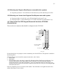
HARDWARE SETUP OF THE BI-PHASE INPUT ................................................. 30
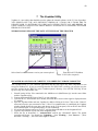
6 VTOOLSPRO UTILITY SOFTWARE .................................................................................. 31
6.1
VToolsPro Installation ............................................................................................ 31
6.2
Editing the configuration file v1s.cfg ...................................................................... 31
6.3
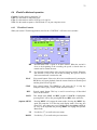
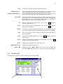
VToolsPro Menus................................................................................................... 32
6.4
VToolsPro Modes of operation ............................................................................... 33
6.4.1
VToolsPro Controls ........................................................................................ 33
6.4.2
VtoolsPro Clips ............................................................................................... 34
3
6.4.3
VtoolsPro Copy (add clips to existing material) ............................................. 36
6.4.4
VtoolsPro View ............................................................................................... 37
6.5
SCSI Copy using VToolsPro ................................................................................... 37
6.6
The Ethernet Option ................................................................................................ 37
6.7
Command Prompt Functions for the PC version:................................................... 39
7
THE VUPDATER UTILITY ................................................................................................ 40
7.1
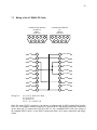
Wiring of the V1 RS422-PC Cable.......................................................................... 42
7.2
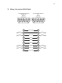
Wiring of the V1 RS422-Mac Cable ........................................................................ 43
7.3
Wiring of the standard RS422 Cable....................................................................... 44
7.4
Wiring of the RS422 Chase cable............................................................................ 45
8
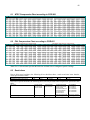
DISK RECORD TIMES FOR VARIOUS COMPRESSION RATIOS.......................... 47
8.1
NTSC Compression Chart according to CCIR-601 ................................................ 48
8.2
PAL Compression Chart according to CCIR-601 .................................................. 48
8.3
Restrictions.............................................................................................................. 48
9 USING THE RCV1 REMOTE CONTROL ................................................................... 49
10
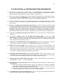
APPLICATION AND TROUBLESHOOTING INFORMATION .............................. 50
11
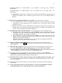
CONNECTING THE V1 TO A WORKSTATION.................................................... 52
11.1 Connection to the DAWN workstation (v 4.3c or later) .......................................... 52
11.2 Connection to the Akai DD-1500 with RS422 control (recommended) .................. 52
11.3 Connection to the Akai DD-1500 in CHASE RS422 Mode..................................... 52
11.4 Connection to the Fairlight ..................................................................................... 53
11.5 Connection to the Microlynx, the Lynx 1 and Lynx 2 synchronizers ...................... 53
11.6 Connection to the Sonic Solutions........................................................................... 53
11.7 Connection to the Pro-Tools 4.0 ............................................................................. 53
11.8 Connection to the Orban AUDICY VX.................................................................... 54
11.9 Connection to the Dyaxis II..................................................................................... 54
11.10
Most Common Connection .................................................................................. 54
11.11
List of DAWs & Editors currently supported by the V1(*) ................................... 55
11.12
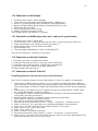
Using the V1 with Edit Controllers..................................................................... 55
12
CHANGES AND ADDITIONS / VTOOLSPRO .......................................................... 57
12.1 Upgrading to version 2.0 ........................................................................................ 57
13
INSTRUCTIONS FOR INITIAL SETUP & TRANSPORT ...................................... 58
14
MOUNTING SCSI DRIVES ...................................................................................... 59
14.1 Important Note about using Jaz Drives................................................................... 59
14.2 Mounting one Jaz drive only ................................................................................... 59
14.3 Mounting two Jaz drives ......................................................................................... 60
14.4 Mounting one Kingston Data-Express removable drive system ............................. 61
14.5 Mounting two Kingston Data-Express removable drive systems............................ 63
14.6 Mounting one Jaz and one Kingston Data-Express removable system................... 63
14.7 Setup of the Fast SCSI Seagate Barracuda4 hard drive ST15150N ....................... 63
14.8 Setup of the Micropolis 3243av 4 GB hard drive.................................................... 64
14.9 Setup of the Seagate Ultra SCSI hard drives 4 GB, 9 GB & 18 GB ....................... 65
14.10
Setup of the Magneto-Optical Drive (MOD) NIKON BELUGA DD53 .............. 66
14.11
Setup of hard drives other than Seagate Ultra SCSI models .............................. 67
14.12
Notes on JAZ cartridges...................................................................................... 67
15
NOTES FOR THE V1M .................................................................................................. 68
16
THE V1-2000 SERIES ................................................................................................... 69
4
WARRANTY
Doremi’s warranty obligations are limited to the terms set forth below:
Doremi Labs, Inc. (“Doremi”) warrants this hardware product against defects in materials and
workmanship for a period of ONE (1) YEAR from the date of original retail purchase.
If you discover a defect, Doremi will, at its option, repair, replace, or refund the purchase price of this
product at no charge to you, provided you return it during the warranty period, with transportation
charges prepaid, to the authorized Doremi distributor from whom you purchased it or to any other
authorized Doremi distributor within the country of original retail purchase. (You can obtain additional
information by contacting Doremi at the address printed on this certificate). To each product returned for
warranty service, please attach your name, address, telephone number, and a copy of the bill of sale
bearing the appropriate Doremi serial numbers as proof of date of the original retail purchase.
If your product fails during the warranty period while you are out of the country of original retail
purchase, you may have it repaired (no refunds or replacements are provided) at your expense by an
authorized Doremi distributor in the country in which the product failed. You may obtain a refund for the
repair costs by submitting a claim to Doremi (instructions are obtained by contacting Doremi at the
address printed on this certificate).
This warranty applies only to hardware products manufactured by or for Doremi that can be identified by
the “V1” trademark, trade name, or logo affixed on them. Doremi software is warranted pursuant to a
separate written statement packed with the software. Doremi does not warrant any products that are not
Doremi products. Note that most third-party products have a manufacturers' warranty. This warranty
does not apply if the product has been damaged by accident, abuse, misuse, or misapplication; if the
product has been modified without the written permission of Doremi; or if any Doremi serial number has
been removed or defaced.
THE WARRANTY AND REMEDIES SET FORTH ABOVE ARE EXCLUSIVE AND IN LIEU OF
ALL OTHERS, WHETHER ORAL OR WRITTEN, EXPRESS OR IMPLIED. DOREMI
SPECIFICALLY DISCLAIMS ANY AND ALL IMPLIED WARRANTIES, INCLUDING, WITHOUT
LIMITATION, WARRANTIES OF MERCHANTABILITY AND FITNESS FOR A PARTICULAR
PURPOSE. No Doremi distributor, agent, or employee is authorized to make any modification,
extension, or addition to this warranty.
DOREMI IS NOT RESPONSIBLE FOR SPECIAL, INCIDENTAL, OR CONSEQUENTIAL
DAMAGES RESULTING FROM ANY BREACH OF WARRANTY, OR UNDER ANY OTHER
LEGAL THEORY, INCLUDING BUT NOT LIMITED TO LOST PROFITS, DOWNTIME,
GOODWILL, DAMAGE TO OR REPLACEMENT OF EQUIPMENT AND PROPERTY, AND ANY
COSTS OF RECOVERING, REPROGRAMMING, OR REPRODUCING ANY PROGRAM OR DATA
STORED IN OR USED WITH DOREMI PRODUCTS.
Doremi Labs, Inc.
3631 Cahuenga Blvd. West
Los Angeles, CA 90068
5
WARNING
THIS APPARATUS MUST BE EARTHED
IMPORTANT
WARNING
Power requirements for electrical equipment vary from area to area. Please ensure that your V1 meets the
power requirements in your area. If in doubt, consult a qualified electrician or Doremi Labs, Inc. dealer.
120VAC
220-230/240VAC
240VAC
@60Hz for USA and CANADA rating 1A
@50Hz for Europe rating 0.5A
@50Hz for Australia rating 0.5A
AVIS
Le voltage peut differer d’un pays a l’autre. Il faut que le V1 soit ajuste au voltage du pays.
LA SOURCE DE PUISSANCE DOIT AVOIR UN CONDUCTEUR CONNECTE A LA TERRE.
Toutes reparations doient etre effectuees par une personne qualifiee.
AFIN D’EVITER UN CHOC ELECTRIQUE, VEUILLEZ NE PAS ENLEVER LE CAPOT.
PROTECTING YOURSELF AND THE V1
Never touch the AC plug with wet hands
Always disconnect the V1 from the power supply by pulling on the plug, not the cord.
Allow only a Doremi Labs, Inc. dealer or qualified professional engineer to repair or reassemble the V1.
Apart from voiding the warranty, unauthorized engineers might touch live internal parts and receive a
serious electric shock
Do not put, or allow anyone to put any object, especially metal objects into the V1
Use only an AC power supply. Never use a DC power supply.
If water or any other liquid is spilled into or onto the V1, disconnect the power, and call your dealer.
Make sure the unit is well ventilated, and away from direct sunlight.
To avoid damage to internal circuitry, as well as the external finish, keep the V1 away from sources of
direct heat (stoves, radiators, etc.).
Avoid using aerosol insecticides, etc. near the V1. They may damage the surface, and may ignite.
Do not use denatured alcohol, thinner or similar chemicals to clean the DR8. They will damage the
finish.
Modification of this equipment is dangerous, and can result in the functions of the V1 being impaired.
Never attempt to modify the equipment in any way.
In order to ensure optimum performance of your V1, select the setup location carefully, and make sure
the equipment is used properly. Avoid setting up the V1 in the following locations:
1. In a humid or dusty environment
2. In a room with poor ventilation
3. On a surface which is not horizontal
4. Inside a vehicle such as a car, where it will be subject to vibration
5. In an extremely hot or cold environment
6
WARNING!!
To prevent fire or shock hazard, do not expose this appliance to rain or moisture
CAUTION
RISK OF ELECTRIC SHOCK
DO NOT OPEN
CAUTION:
!
TO REDUCE THE RISK OF ELECTRIC SHOCK,
DO NOT REMOVE COVER (OR BACK).
NO USER-SERVICEABLE PARTS INSIDE.
REFER SERVICING TO QUALIFIED SERVICE PERSONNEL.
The lightning flash with the arrowhead symbol superimposed
across a graphical representation of a person, within an equilateral
triangle, is intended to alert the user to the presence of uninsulated
“dangerous voltage” within the product’s enclosure; that may be
of sufficient magnitude to constitute a risk of electric shock.
!
The exclamation point within an equilateral triangle is intended to
alert the user to the presence of important operating and
maintenance (servicing) instructions in the literature
accompanying the appliance.
7
CE NOTICE
indicates compliance of the device to the EMC (Electromagnetic
Marking by the symbol
Compatibility) directive and to the Low Voltage directive of the European Community. Such marking is
indicative that this device meets or exceeds the following technical standard:
•
EN 55022 "Limits and Methods of Measurement of Radio Interface Characteristics of Information
Technology Equipment."
A "Declaration of Conformity" in accordance with the above standard has been made and is on file at
Doremi Labs, Europe, Valbonne, France.
8
INTRODUCTION
If you are a Digital Audio Workstation (DAW) user and are tired of waiting for your analog tape
VTR to locate and follow up with your DAW, you would need to replace your video tape
machine with a random access digital video recorder/player that would respond instantly to your
locate commands and communicate efficiently with your DAW to allow you to finish your work
faster.
If you have an application that requires instant locate and playback from any time code position
you would need a random access digital video recorder/player.
The V1 is the first generation of our random access digital video equipment that uses magnetic
(hard drives) or magneto optical (MOD) drives as a recording medium.
To be able to record video on a hard disk it should be digitized which means that the analog
video information must be converted to a digital data stream. Every frame of NTSC (or PAL)
video contains 525 (or 625) lines that has 858 (or 864)pixels each. In a typical A/D conversion
every pixel is coded on 16 bits (2 Bytes), which yields a data stream of:
NTSC: 525*858*2=900900 bytes/frame or 29.97*900900=27 MB/s.
PAL: 625*864*2= 1080000 bytes/frame or 25*1080000=27 MB /s.
You see that in both cases the drive should be capable of handling a transfer rate of at least
27MB/s. This figure does not include any audio tracks. Since the transfer rate of various media
range between 1MB/s and 16MB/s, to record the video you would need to use RAID systems
(multiple drives chained together to achieve faster transfers) or compress the video data stream
by sacrificing picture quality.
Two compression techniques are becoming popular: Motion JPEG and MPEG.
Motion JPEG consists on compressing every field of video and save the data on the drive
MPEG consists on compressing only few fields/sec called reference fields and then recording the
difference between each new field and the reference fields. MPEG compression requires very
sophisticated techniques but yields a better transfer rate than JPEG for the same video quality.
Since the price of the media is going down day after day, the MJPEG solution is still the most
viable solution for a lot of applications.
The V1 uses a constant block size (CBS) Motion JPEG algorithm. With traditional JPEG
algorithms, depending on video complexity, the size of each JPEG field can vary thus requiring
maintaining a list to indicate the start of each field on the drive. In the CBS all fields have the
same maximum size. This is an overkill for non-complex pictures but it does not require
maintaining a list indicating the start of each field because they are all the same size.
Since not all lines and pixels are useful, the V1 only compresses the valid 480 lines and 720
pixels/line for NTSC (576 lines and 720 pixels/line for PAL) thus making the non-compressed
data stream 20.71 MB/s in NTSC (20.73 MB/s in PAL).
In addition to the video, and regardless of the compression ratio used, the V1 records 0, 2 or 4
tracks of uncompressed audio (sampled at 48Khz), one time code track and allocate space on
each drive for saving the setup information. Each audio sample is coded on 2 bytes (2*2*48000=
192 KB/s) and every field of time code is sampled on 80 bytes (29.97*2*80= 4.795 KB/s for 2
channels in NTSC and 25*2*6= 4 KB/s for 2 channels in PAL).
Hopefully, this introduction to digital video, has explained to the reader the principles of digital
video recording.
9
1 Quick Startup Guide
This chapter assumes the most common hardware setup: V1 equipped with a removable hard drive using
the Kingston Data Express system.
1. Plug the hard drive carrier in the Data Express receiver and turn the key counter clockwise until it
locks
2. Power the unit ON by flipping the switch to the ON position
a. If you keep watching the LCD display on the RCV1 or VToolsPro, you will see a “No Disk”
message displayed for about 30 to 60 seconds (the time it takes for the hard drive to be
mounted)
i. If everything is running properly, the “No Disk” message should disappear and you
should get one of the following:
1. A message saying “No V1 Disk”. This means that this is the first time this
drive is mounted on a V1 unit. If you want to start using the drive, go to the
Menu, set the desired Compression ratio and Initialize the drive
2. No message other than the Time Code and the Stop. This means that the
drive is recognized as a V1 drive and is ready to be used.
ii. If the “No Disk” message does not disappear for more than 2 minutes, then the V1 is
having a problem recognizing the SCSI drive. In most cases, we found that the
internal SCSI cable is disconnected from the Data Express receiver inside the V1
unit or the SCSI terminator supplied is not installed on the back of the V1. If it’s not
the case, the problem would be either from the Data Express carrier, receiver or the
drive itself.
b. If you keep watching the LCD display on the RCV1 or VToolsPro and you don’t see the
message “No Disk”, press the Menu button. If the menu disappears and you don’t get a
response, the V1 itself has a problem starting up. Contact Doremi Labs, Inc. Tech Support.
3. Plug a valid video source on the composite input of the V1.
4. Plug a working monitor on the composite out of the V1
5. Go to the Menu and make sure Input Source is set to Composite
6. Go to Option Menu 3 (Video), press the Toggle Key until you reach the Pattern Sub-menu, then
press the ++ key to set the Pattern ON. This should display a pattern on your monitor. Press the ++
key again to set the Pattern OFF, then hit Escape.
7. If you have something recorded on the disk, it will be displayed on the monitor and hitting the Rec
button should set the unit in EE mode.
8. If you see a valid video signal on your monitor, you can press Rec and Play at the same time to start
recording on the V1
9. Hit Stop to finish the recording
10. If the picture starts flashing between color and black and white, go to the Sync Source Menu and set
it to either Internal or Input. This usually happens if the Sync Source selected is not connected
For more information about the bold letters, refer to Chapter 1 where you will find every Menu and
Option Menu command listed and explained.
10
2 MENU SELECTIONS
If your front panel EPROM on the V1 has version V1.20 or higher, you have access to two different sets
of menus. Pressing the MENU key will allow access to the Standard menu and pressing OPTION
MENU (hold the OPTION key while pressing MENU) will allow access to the Optional menu. If your
front panel EPROM only shows the standard menu, and you need to use the optional menu, you can
either use the VToolsPro utility or request a front panel EPROM programmed with version V1.20 or
higher. Do not confuse the front panel EPROM (socketed 40 pin DIP IC on the RCV1 front panel board)
version V1.20 with the V1 Flash EPROM (socketed 32 pin PLCC IC on the DVP100 main PC board)
version V1.20.
2.1
Standard Menu
The MENU key will call up the menus allowing the user to define the set-up of the V1 unit. The up
(or down arrow key ) will allow the user to get to the next (or previous) menu selection.
arrow key
The Toggle/Select key ( ) generally sets the parameters for the selected menu . Once menus are set-up,
pressing the ESC or MENU keys will save the settings and quit the menu mode. All the settings related
to the recording i.e. Remote/Local, Time Mode, Sync Source, Input Source, etc. are automatically saved
on the current disk when you exit the menu mode (on version 1.9 and lower, the V1 will wait for a STOP
command before saving the set-up on the current drive)
(00)
(01)
Control
Time Mode
Selects the mode of control for the V1. The Toggle/Select key (
switch between :
) will
Local
For front panel control of the V1
Remote
For control of the V1 by an external edit controller or
workstation via the rear panel RS-422 connector 1. RS422 connector 2 is to be used only for the desktop
remote control RCV1 from Doremi Labs, Inc.
Selects the Time Code source of the V1 during playback. Regardless of
the setting for this option, the V1 will record the time code present on
the video input on the VITC track, and the time code present on the LTC
input on the time code track. This menu option will allow you to choose
the time code during playback. The Toggle/Select key ( ) will switch
between :
A Time
Absolute Time, the time code displayed on the V1 front
panel and present on the TIME CODE OUT connector
during playback or record is generated internally by the
V1. A Time represents the time elapsed since the start of
the recording unless a time code offset has been set. See
Section 4.1.4, “Time Code Offset”.
Time Code
During record the time code present on the TIME
CODE IN connector will be recorded on the time code
track (guide track) of the V1 active drive, a valid LTC
signal should first be fed to the V1 LTC IN connector.
The time code displayed on the V1 front panel and
present on the TIME CODE OUT connector during
playback or record is the same time code recorded on
the time code track, unless a time code offset has been
set. See Section 4.1.4, "Time Code Offset".
11
(02)
(03)
Sync from
Chase
A Time as LTC
If you are using A Time (with or without an offset) as
your time code and if your controller requires time code,
you should choose this option which will make the A
Time look like Time Code on the RS422 connection.
VITC Time
During record, the time code embedded in the video
input signal (VITC) will be recorded on the VITC track
of the V1 active drive. The time code displayed on the
V1 front panel and present on the VITC OUT connector
during playback or record is the same time code
recorded on the VITC track, unless a time code offset
has been set. See Section 4.1.4, "Time Code Offset".
Specifies the sync reference during playback. The V1 is always locked
to the Input when recording. The Toggle/Select key ( ) will switch
between :
Auto
The V1 syncs to the SYNC IN input.
Sync In
The V1 syncs to the SYNC IN input. Auto and Sync In
are the same.
Input
The V1 syncs to the VIDEO IN input.
Internal
The V1 syncs to its own internal clock.
Specifies how the V1 will chase to time code. The Toggle/Select key
( ) will switch between :
Off
LTC
MTC
Serial TC
(RS422)
Biphase
Normal mode of operation when the unit is controlled
by a workstation via the 9 pin connection.
In this mode the V1 will chase the time code fed through
the TIME CODE INPUT jack. This mode is
recommended when no RS422 9 pin control is present
(See Sections 4.2.1 and 4.2.2, Chase Play.)
In this mode the V1 will chase the time code fed through
the MIDI IN connector. This mode is recommended
when no RS422 9 pin control is present.
In this mode the V1 will chase the time code received
on the RS422 connection. This mode requires a special
cable and it is recommended only if no RS422 9 pin
control is present. Please refer to Paragraph 7.4,
"Wiring of the RS422 Chase Cable" for more
information on how to build the cable.
In this mode the V1 will chase the Biphase input clock
signal. Option Menu (18) "Clks/Frame" should be setup
properly in order to select the clock frequency. Please
refer to option menu (18) at the end of Section 1.2. To
use the Biphase mode, the internal cable of the second
RS422 port should be connected to J3 on the main
motherboard. Please refer to Section 4.0 for
information.
The Biphase mode is only available on
units with serial number 201 and higher using firmware
version 1.99E or higher.
Note: The Chase to LTC Mode above is different than the OPTION
PLAY Command also referred to as Chase Command (note the
difference between Mode and Command, See Sections 4.2.1 and 4.2.2
for an explanation of the difference).
12
(04)
Mount
(STRIPE)
Mounts all drives that are not mounted. To mount a disk, press the
Toggle/Select key ( ). A message will appear on the LCD screen: “Are
you sure?” :
♦ If you want to mount, hold the OPTION (.) key and press the
Toggle/Select key ( ) again, all drives will be mounted.
♦ If you change your mind and don't want to mount, press ESC.
Note: If you have not changed your front panel EPROM to version
V1.20, this menu command is called STRIPE, and to mount drives you
need to Toggle it ON then OFF once.
(05)
Input From
Specifies which video input of the V1 is active. The Toggle/Select key
( ) will switch between COMPOSITE and S-VIDEO. The SDI
selection is available only on the V1D.
(06)
Compress
Specifies the Compression Ratio. An initialize command should be
executed in order for the new compression ratio to be valid for the new
recording. Available ratios are: 2:1(*), 2.5:1(*), 3:1(*), 3.5:1(*), 4:1,
5:1; 6:1, 7:1, 8:1, 9:1, 10:1, 12:1, 14:1, 16:1, 20:1, 24:1, 34:1. Pressing
the Toggle/Select key ( ) will increase the ratio until it reaches 34:1,
then it will start over from 4:1. Holding down the OPTION key (.) while
pressing the Toggle/Select key ( ) will decrease the ratio. For more
information refer to Section 7, "DISK RECORD TIMES FOR VARIOUS
COMPRESSION RATIOS".
(*) Available only on units with over 2MB of internal SRAM like the
V1D/2M.
(07)
Initialize
This command wipes (deletes) all previous recordings, and writes all the
new set-up parameters selected in the menus on the active drive. A disk
that was never initialized on the V1 will display the message "No V1
disk" until it gets initialized. Use this command to change the
compression ratio or after changing any of the rear panel DIP switches.
To initialize a disk, press the Toggle/Select key ( ).
A message will appear on the LCD screen: “Are you sure?” :
♦ If you want to initialize, hold the OPTION (.) key and press the
Toggle/Select key ( ) again, the LCD will display "Initialize.." and
initialize the disk. Once done, the message "Initialize.." will
disappear and the drive is now ready for recording.
♦ If you change your mind and don't want to initialize, press ESC.
(08)
Format
This command wipes all previous recording and prepares the active
drive for optimal V1 performance. You should use this command at least
once on every new drive you install on the V1. The Format command
should always be followed by an Initialize command. To format a disk,
press the Toggle/Select key ( ). You will be prompted with the
following message: “Are you sure?” :
♦ If you want to continue, hold the OPTION (.) key and press the
Toggle/Select key ( ) again, the LCD will display "Formatting..."
and will format the disk. Once done, "Formatting..." is cleared and
the drive is now ready for the Initialize operation.
CAUTION NOTE !!
Formatting a drive is a long procedure, please do not attempt to
use the V1 until the format operation is complete and DO NOT
SHUT OFF THE V1 DURING THE FORMAT OPERATION
(If the V1 is switched off during the format operation, the drive may
require a low level format operation on a computer before it can be
used again on a V1).
13
The format operation is a long procedure that takes approximately
around 20 mn for a JAZ-1GB, 1 h 20 for a 4 GB drive and around 2
h 30 for a 9 GB drive.
♦ If you change your mind and don't want to format, press ESC.
NOTE: THE FORMAT COMMAND ONLY WORKS ON V1
DRIVES, IF THE LCD DISPLAYS THE MESSAGE: "NO V1
DISK", THE DISK NEEDS TO BE INITIALIZED BEFORE IT
CAN BE FORMATTED.
Once Format and Initialize have been executed on a drive, it is not
necessary to Format again. Initialize is enough for erasing the drive.
(09)
Drop Frame
This option is only valid when Time Mode is set to A-Time or A-Time
As LTC in NTSC mode (See Section 4.2, "Special Playback Functions").
The Toggle/Select key ( ) will switch between Drop and Non Drop.
To set your Time Code Offset locate to any position on the drive,
manually enter the new time code desired at that location and hold the
OPTION key while hitting the IN key. The Time Code offset will be
saved on the drive.
(10)
Time Left
This menu selection will display how much time (HH:MM:SS:FF) is
still available on the disk from the end of the existing recording. The
total duration is calculated using the disk capacity detected, the
compression rate, the 8 pixel jumper setting and the one or two fields
jumper setting. After an Initialize command, Time Left displays the
full capacity of the drive in "HH:MM:SS:FF" format. If you call this
menu during recording, it will show the time left at the moment it was
activated. When the drive is fully recorded, "Time Left" will display
00:00:00:00 and you are only allowed to record over existing material.
When this menu selection is active pressing the Toggle/Select key ( )
will update the time left.
Menus (00), (01), (02), (04), (05) and (06) are saved on the active drive. So if this drive is mounted on
another V1 unit, all these settings will be recovered.
2.2
Optional Menu
V1 Info.
If you are in Option Menu (00) and hit the down arrow key , the V1
will display information about the unit. The Toggle ( ) key will
switch between: Version Number, IP address, Ethernet Port Address and
finally the amount of RAM used on that unit.
(00)
Auto Play
If you enter a segment number that is already defined (See Section 4.2.6,
"Segment Definition & Playback"). The V1 will play that segment every
time it mounts that drive. This function can also be used to automatically
locate to a start point every time the disk is mounted. All you need to do
is set the IN and OUT time at the same location for the auto-play
segment.
(01)
Disk Copy
This feature will allow you to make duplicates of one recording (source)
on one or more drive(s) (target(s) or destination(s)) without the need to
re-record the video thus allowing video, audio time code , segments
definition and menu set-up to be transferred digitally from one drive to
the other. First make sure your source disk is the active drive (when you
hit play, only the source disk should be playing) then power up (insert
cartridge in) your destination drive(s). Engage the Disk Copy menu, the
14
Toggle/Select key (
menus:
) will switch between each of the following sub-
1. Source is :
type the SCSI ID number of the source drive (Valid
range from 0 to 7), then use "++" to go to the next submenu...
2. # Targets: type the number of drives that will act as your
destination drives (Valid range from 1 to 6), if you enter
a value higher than the maximum allowed, the V1 will
default to its maximum, then use "++" to go to the next
sub-menu...
3. Target #1: type the SCSI ID number of the destination drive
number 1 (See Caution below). If you specify more than
one target, you will be prompted for Target #2, etc...,
then use "++" to go to the next sub-menu...
4. Segment #: if you wish to copy only a segment (already defined on
the source drive), enter the segment number, from 1 to
511, and if previous menus 1,2,3 have the values you
need, press ENTER to start the copy process If you
need to perform a full copy, then use "++" to go to the
next sub-menu...
5. Full Disk: if you wish to copy the full disk, and if previous menus
1,2,3 have now the values you need, press ENTER to
start the copy process. If you do not want to perform the
copy operation at this time hit ESC , use "++" or "--" to
go to other sub-menus...
Important notes :
♦ Hitting ENTER after each of these sub-menus will save your choice
and launch the copy operation, so do not press ENTER until you
have entered all the correct values in the sub-menus.
♦ The destination drive must be previously initialized on a V1. The
copy will be aborted if the destination drive is not a V1 drive.
♦ During the copy process, the LCD will display a counter showing
how much is left to be copied (in Gbytes, Mbytes), when finished, it
will display "Completed".
♦ The copy process will only copy valid recordings from the source
drive. If the source drive has invalid recordings or bad sectors in the
recording to be copied, the LCD will display "Copy aborted" and
will abort the copy process. In this case check your recording on the
source drive, and record it again if it is damaged or contains bad
sectors.
♦ Caution! : Your destination drive will be fully erased by the
copy.
(02)
Edit Preset
This feature will allow you to select which audio track(s) to edit/overdub
while the other non selected track(s) are monitored at the same time. The
overdub feature is only supported on the Seagate Ultra SCSI hard
drives with compression ratios of 8:1 (2 fields) or higher (See Section
4.1.3 for other drives).
The Toggle/Select key ( ) will switch between the following
selections:
15
1. A1:
2.
3.
4.
5.
To insert/overdub on audio track 1, select On by
pushing the "++" key. To select Off, press the "--" key.
A2:
To insert/overdub on audio track 2, select On by
pushing the "++" key. To select Off, press the "--" key.
TC:
To insert/overdub time code on the guide track, select
On by pushing the "++" key. To select Off, press the "-" key. Note that you can use the "Time Code Offset"
function and keep this option Off.
Video:
To insert/overdub video, select On by pushing the "++"
key. To select Off, press the "--" key.
Assemble: If this submenu is set to On by pressing the "++" key, all
previous submenus 1., 2.,3. & 4 will default to the On
position and the drive is set for normal recording (video,
audio and time code). You can select Off by pressing
the "--" key. The reason for the On/Off toggle for video
is to allow the V1 to record while in PLAY mode
(Usually required by Editors using RS422 control), in
this case, the sub-menu Assemble must be On.
3. Insert:
In the Off position, the V1 will ignore all previous
settings. When set to ON, the V1 will be in insert mode.
The overdub procedure is explained further in Section 3.1.3.
(03)
Set Video
This menu option will allow you to move the picture horizontally or
vertically. The Toggle/Select key ( ) will switch between:
Delay:
Pattern:
Out:
CH PH:
HTRIG:
HTRIG:
Black:
This parameter sets the delay until the video output goes black
(screen saver). The "--" will move the delay down by 10
seconds, "++" will move it up by 10 seconds. "000" will
disable this feature, "010" will cause the unit to output black
video when the unit is idle for 10 seconds.
Use "++" or "--" to toggle the video pattern ON and OFF.
V1D only. Use the "++" or "--" to select the output as RGB,
YUV or S Video
Chroma Phase. Use the "++" or "--" to increase or decrease the
chroma phase from 0 to 360. You can also enter a number
from the keypad followed by the ENTER key
Use "++" or "--" to set the HTRIG adjustment ON or OFF.
THIS OPTION SHOULD BE SET TO "OFF" FOR ALL
UNITS WITH SERIAL NUMBER 300 OR LOWER.
The "--" will move the picture to the left, "++" will move it to
the right. You can also enter a number from the keyboard
followed by the ENTER key.
Sets the black level to 0V for the Japanese standards and
0.75V for the American standards. Used in NTSC only.
PAL
Switch: 0 or 1. Use the "++" or "--" to set the value according to the
PAL standard used in your area (A or B)
LumaBrit:
Use the "++" or "--" to set the Luma Brightness. 00 is the
default value.
LumaCont:
Use the "++" or "--" to set the Luma Contrast. 00 is the default
value.
ChromaSat:
Use the "++" or "--" to set the Chroma Saturation. 00 is the
default value.
Chroma-
16
Hue:
Use the "++" or "--" to set the Chroma Hue. 00 is the default
value.
This option is not saved on the drive, it is saved on the V1 flash EPROM
only if you execute a Save from optional menu (04).
(04)
Save
This menu option will save all the Flash EPROM settings of the V1. To
write the changes on the Flash EPROM (see Note below), press the
Toggle/Select key ( ).
A message will appear on the LCD screen: “Are you sure?” :
♦ If you want to save, hold the OPTION (.) key and press the
Toggle/Select key ( ) again, The V1 will write the changes on the
Flash EPROM.
♦ If you change your mind and don't want to save, press ESC.
NOTE: THIS FUNCTION SHOULD NOT BE ABUSED BECAUSE
THE FLASH EPROM CAN ONLY BE WRITTEN 2000 TIMES. IF
YOU SAVE YOUR SETTINGS ON THE FLASH EPROM MORE
THAN 2000 TIMES YOU MIGHT DAMAGE IT AND NEED TO
REPLACE IT BY ORDERING A NEW FLASH FROM DOREMI
LABS, INC.
(05)
Disk Access
This menu option will allow you to write protect your drive. The "++" or
"--" keys will switch between Play Only and Play & Record (Default).
When Play Only is selected, you will not be able to record on the disk
or initialize it. This option is saved on the disk.
The "++" or "--" will toggle between Frame Mode ON, OFF and Play
Only. When ON the V1 will stop on a frame and in slow motion it will
play frame by frame. When OFF the V1 will stop on a field and in slow
motion it will play field by field. In Play Only, the V1 will stop on a
field and in slow motion it will play frame by frame. This setting also
affects the Step Recording option.
(06)
Frame Mode
(07)
Step Rec
Step Recording. The "++" or "--" will toggle between Step Recording
enabled or disabled. When enabled, every time the V1 goes into record,
it will only record one frame (or field depending on the Frame mode
setup). This option is useful for animation. When Step Recording is
disabled, the V1 is in normal mode of operation. If you want to record
video only without altering the previously recorded audio, press the
Toggle/Select key ( ). This will give you the option of recording “All”
or “Video Only”. You can switch between the two modes using the “++”
or “--“ keys.
(08)
Clip Menu
The "++" or "--" will go to the beginning of the next or previous clip
(segment). This menu only shows previously defined segments. For
more information on defining segments see Section 4.2.6, "Segment
Definition and Playback"). You can also type the clip number using the
keypad followed by the ENTER key, if you enter an undefined clip
number the V1 will locate to the previous clip. When a clip other than 0
is selected here, the V1 operations will be restricted between the
boundaries of that clip (segment).
(09)
TC burn-in
Time Code Burn-In window. This option is only available on units with
serial number 201 and higher. It will allow the user to define how and
where the burn-in time code window will be displayed on the VITC
output. The Toggle/Select key ( ) will switch between two submenus:
17
Position:
Color:
The "++" or "--" will allow the user to choose one of 6
different positions: Top-Left, Top-Center, Top-Right,
Bottom-Left, Bottom-Center & Bottom-Right.
The "++" or "--" will allow the user to choose one of 5
different selections: Off, White on Black, White on
Background, Black on White & Black on Background.
This selection is saved on the machine after executing (04) Save.
(10)
Audio In
This option is only available on units with serial number 201 or higher
that were purchased with the digital audio option. To ensure loosless
audio on the digital input, it must be sampled at 48.000Khz and phase
locked to the video input. If you feed digital audio at a different
frequency, or at a non phase locked frequency, the V1 will re-sample the
audio at 48Khz which might produce undesirable clicks.
The "++" or "--" will toggle between analog or digital input.
(11)
SCSI Speed
This option is only available on units with serial number 201 or higher.
The "++" or "--" will toggle between 10 MB/sec or 20 MB/sec. This is
the speed of the SCSI synchronous negotiations. A Save command
should be executed after changing this parameter and the unit should be
restarted to use the new speed. If the internal jumper of the unit is set to
ASYNC, this option should be 10MB/sec. If the Internal jumper is set to
SYNC, this option can be set to 10MB/s or 20MB/sec. The combination
SYNC and 20MB/sec should only be used with software version 1.99z
or higher. SYNC mode should only be set by an authorized technician.
IF YOU ARE NOT SURE WHETHER YOUR JUMPER IS SET TO
SYNC OR ASYNC, SET THE SCSI SPEED TO 10MB/SEC. The
Toggle Key will allow you to switch between 8bit and 16bit. You should
leave this option set to 8bit unless instructed by a Doremi technician to
do otherwise.
(12)
V1 Type
The "++" or "--" will toggle between Player Only or Rec/Player. This
option is used when more than one V1 unit are connected to the same
drive or RAID. You can only have one unit set in Rec/Player and all the
rest should be Player. The Rec/Player is the only unit allowed to record
on the network.
Important Note: When the unit is in Player Only mode, all operations
that write to the active drive are denied, including record, initialize,
format, etc..
(13)
Video Type
The "++" or "--" will toggle between NTSC and PAL. This option menu
replaces jumper number 6 on the back panel DIP switch. If you want the
new setting to be the default startup setting, a Save command should be
executed after changing this parameter. If the unit does not allow you to
switch to PAL, turn the unit OFF, set DIP switch number 6 UP and
restart the unit.
(14)
Nb Pixels
The "++" or "--" will toggle between Full and Limited (-8 pixels). This
option menu replaces jumper number 7 on the back panel DIP switch. If
you want the new setting to be the default startup setting, a Save
command should be executed after changing this parameter.
(15)
Decimation
The "++" or "--" will toggle between ON (360) and OFF (720). This
option menu replaces jumper number 8 on the back panel DIP switch. If
you want the new setting to be the default startup setting, a Save
command should be executed after changing this parameter. OFF is a
better quality picture.
(16)
Nb Field
The "++" or "--" will toggle between Two and One. This option menu
replaces jumper number 9 on the back panel DIP switch. If you want the
18
new setting to be the default startup setting, a Save command should be
executed after changing this parameter.
(17)
SCSI ID
The "++" or "--" will toggle between 0, 1, 2, 3, 4, 5, 6, and 7. The
selection represents the SCSI ID number of the V1 after restart. Do not
use a SCSI ID number for the V1 that conflicts with any installed
drive. A Save command should be executed after changing this
parameter.
(18)
Clks/Frame
The "++" or "--" will toggle between 01, 02, 04, 10. The selection
represents the number of clicks on the incoming Biphase signal per
video frame (01= 1 click per frame). In PAL 25 frames/sec, 01=25Hz,
02=50Hz, 04=100Hz, 10=250Hz. If you want the new setting to be the
default startup setting, a Save command should be executed after
changing this parameter.
(19)
Emulation
The "++" or "--" will toggle between V1 (default) and BVW-75. If you
want the new setting to be the default startup setting, a Save command
should be executed after changing this parameter.
(20)
# Audio Ch
The "++" or "--" will toggle between 0, 2 and 4 which designate the
number of audio channels that will be recorded after initialization of the
drive. 0= No audio recorded, 2= Audio on channels 1&2 will be
recorded, 4= Audio on channels 1, 2, 3 & 4 will be recorded.
(21)
Jog On
The "++" or "--" will toggle between “1&2” and “3&4”. When “1&2” is
selected and when the V1 is playing at any speed below 100%, the
output on tracks 3 and 4 will come from the audio recorded on channels
1&2. When “3&4” is selected and when the V1 is playing at any speed
below 100%, the output on tracks 1 and 2 will come from the audio
recorded on channels 3&4. When the speed is 100% and above, every
track will play its own recorded audio.
(22)
Loop Mode
(23)
Edit Time
(24)
Stripe TC
(25)
Odd Fields
(26)
Stop Chase
The "++" or "--" will toggle between OFF and ON. When this option is
set ON, the V1 will record (play) in a loop specified by the clip selected
in option menu (8) “Clip Menu”.
The Toggle ( ) key will switch between IN and OUT. When using the
EDIT ON OFF commands from a P2 editor, the “++” or --“ keys in the
IN submenu will set the time that the V1 will start recording after
receiving the EDIT ON command to 4, 5, 6, 7, 8, 9 or 10 fields. In the
OUT submenu, the number of fields will set the time that the V1 will
stop recording after receiving the EDIT OFF command.
This command will stripe Time Code with black video and no audio.
The striping will start at the time line position starting with the time line
displayed on the LCD. Example: If you want to stripe time code
beginning at 01:00:00:00, you would: Initialize your drive. Create a one
hour offset using the OPTION IN command. Then use this Option
Menu command by pressing the Toggle ( ) key. The LCD will reply:
"Are you sure". If you are, hold the OPTION Key and press the Toggle
( ) key, if not just hit the ESC key.
Stripe TC does not work if your drive is initialized in Limited Window
or Decimation mode ON.
The speed shown in percentage after the word “Under” will define the
speed under which the V1 will only play odd fields. If you want to play
odd and even fields at all speed, use the “--“ key to select 0%.
The number of frames defined in this option menu will set the freewheel of the chase mode between 1 and 10 frames or “0”. When set to
“0”, the V1 will play the same field for the whole duration of the time
code drop-out. When set to a value between 1 and 10, the V1 will play
the same field for the specified amount of frame(s) before it stops and
19
(27)
Fast Mode
(28)
(29)
Jog Speed
Still Mode
wait for the new time code to chase. This function is useful to reduce the
audio noise during the chase command. If you know that your source
does not have drop-outs in the time code, set this value to 1.
The settings allowed are Normal or Enhanced. All speed faster than
normal would look much better in enhanced mode but to be able to use
this mode you need to have a fast hard drive (7200 RPM or higher). All
units with serial number <200 should use the Normal mode. All units
connected to a V1Xserver should use the Normal Mode. All units
running with a fast local drive can use the Enhanced.
Sets the maximum speed in Jog mode to 100% or no limit.
Sets the mode of the V1 stop mode to either show a field/frame from the
drive (Still) or show the image present on its input (EE). In EE mode,
pressing Stop more than once will show the image from the drive.
Optional menus (05) (06) (07) are saved on the active drive. So if the drive is mounted on another V1
unit, these settings will be recovered.
If your unit has software version 1.99 or higher, Positions 1, 2, 3, 6, 7, 8, 9 and 10 on the DIP switch
are no longer valid AND MUST ALL BE SET IN THE UP POSITION WHILE THE UNIT IS
POWERED OFF. Positions 4 and 5 on the DIP switch should be set to the low position to allow
proper termination of the SCSI bus.
20
3 FRONT PANEL DESCRIPTION
The V1 front panel contains a space for two (3 1/2" or 5 1/4") half-height SCSI drives or one full-height
(5 1/4") SCSI drive, volume potentiometers for setting the audio input record level, transport control
keys, function keys, a jog/shuttle wheel, a numeric keypad, and the main power switch.
3.1
SCSI Drives
The V1 is shipped with a choice of standard SCSI storage devices : 3 1/2" half-height or low-profile (LP)
hard drives mounted internally inside the V1 or in a removable tray (Data-Express), IOMEGA® JAZ™
drive with 1 or 2 GB magnetic removable cartridge and 2.6 GB magneto-optical drive and cartridge.
When mounted in a removable tray, hard drives can be removed (or installed) while the V1 is on-line
(without the need to shut the unit off). To remove (or install) a drive, insert the supplied drive key into
the key slot on the removable tray below the lit SCSI ID number and turn it clockwise (or counterclockwise). When removing a drive, turning the key clockwise will unlock the drive and cut power off
from it causing it to spin down. Before removing a drive, wait until it has completely finished
spinning down. This will usually take about 10 to 20 seconds depending on the drive. It is not necessary
to set a SCSI ID for the V1 internal removable drives. The ID is set by the removable tray inside the V1
hardware. All V1 internal drives should be non-terminated, the external SCSI termination supplied with
the V1 should be mounted before powering up.
Additional SCSI drives can be added to the V1 rear panel SCSI connector. All drives on the external
chain should be non-terminated except for the last drive in the chain which should be terminated. When
no drives are connected externally, connect the supplied SCSI terminator to the SCSI connector on the
back of the V1.
DO NOT USE SCSI ID7 FOR DRIVES, this ID can only be used by the V1 itself.
3.2
Volume
The two volume potentiometers located on the left of the V1 time-code display are used to set the audio
input level during the recording process only. They have no effect at playback. Volume levels are
displayed along the bottom of the LCD display during recording and playback. 0dB on the V1 scale
represents 0dB digital or +20dB analog. +4dB (0VU) is at -20dB on the V1 scale. Audio recordings
should be made at around -12dB on the scale with peaks between -12dB and 0dB. The 0dB level is the
absolute maximum, going over it will produce digital clipping.
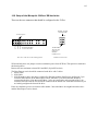
3.3 LCD Time Code Display
The first line of the Time Code display shows the time location of the video material using the following
format : “HH:MM:SS:FF F1/F2” where "HH" represent the hours from 00 to 23, "MM" represent the
minutes from 00 to 59, "SS" represents the seconds from 00 to 59, "FF" represents the frames from 00 to
24 in PAL and 00 to 29 in NTSC, "F1/F2" represent the field: "F1" for odd fields and "F2" for even
fields. This display will show either Absolute Time or Time Code depending upon what the user has
selected in the "Time Mode" (01) Menu.
In addition to the audio input levels the second line displays the following:
♦ At the V1 start-up, the bottom left displays the version of the V1 software installed on the flash
EPROM (example, V2.0 when version 1.20 is installed), then No Disk is displayed on the left side
and Stop is displayed on the right side until a valid drive is recognized on the SCSI bus of the V1, in
such case No Disk will disappear and only Stop will be displayed indicating that the V1 is now ready
to access the drive. If No Disk is still displayed even though a disk was mounted, the V1 did not
recognize the disk. Check for SCSI ID conflict.
21
♦ During transport controls, the current operation is shown on the right side of the display: PLAY,
STOP, REWIND, FORWARD, RECORD, JOG, SHUTTLE, VAR..
("VAR" is indicated during play in chase on LTC/MTC or in variable speed from RS422)
♦ During shuttle movement, the shuttle speed is shown as :
If forward shuttle : ">> xx %" with xx % = 10%, 20%, 50%, 100%, 200%, 500%, 1000%
If reverse shuttle : "<< xx %" with xx % = 10%, 20%, 50%, 100%, 200%, 500%, 1000%
♦ During segment playback, the remaining time up to the OUT point is shown as "sss : MM.SS", where
"sss" is the number of the segment played from 001 to 511, "MM.SS" is the remaining time up to the
OUT point of the segment played in mn:sec
♦ During formatting, the message Formatting... is shown. During initialize, the message Initialize is
shown. During drive copy, the message Copying... is shown, once done, Copy Complete is shown
and if source drive has invalid recording, Bad Segment or Copy aborted is shown.
♦ During the drives mounting (insert) and un-mounting (eject), the message No disk is displayed.
3.4
Numeric Keypad
This keypad is used to enter numeric data such as time code addresses, in and out points, locate points,
etc. To enter data, simply begin typing the numbers and the display will automatically overwrite. To
abort an operation, press the ESC (escape) key. The display will revert to its previous setting. The BKSP
(Backspace) key can be used to correct typing errors.
3.5
Transport Controls
The V1 standard tape-style transport controls are:
3.6
REW
Rewind control button with a speed of 40 times normal. When the
rewind is close to the beginning of the recording, the speed is slowed
down to normal until it reaches the start.
FF
Fast forward control button with a speed of 40 times normal. When the
fast forward is close to the end of the recording, the speed is slowed
down to normal until it reaches the end.
PLAY
Play control button. If the active drive has recorded material, pressing
the PLAY key will start playback from the current location at normal
speed and the green LED will go ON.
STOP
Stop control button. The STOP key will cause the V1 to stop any
transport control (Play, record, rewind, fast forward).
REC
Record control button. This key is used in several ways described later
in this menu.
Function Keys
MENU
ARROW UP
ARROW DOWN
Pressing this key will engage the menu mode. Pressing the MENU key
again will return the V1 to the time code display mode. (You may also
press ESC.) all settings are saved.
Use this key (
) to scroll to the next menu.
Use this key ( ) to scroll to the previous menu.
22
TOGGLE/SELECT
Use this key (Double arrow,
menus.
)
to change selections within most
WHEEL
This key activates the Jog/Shuttle wheel. When active, the amber LED
above the button will go ON. Pressing the key while active will toggle
between jog and shuttle :
♦ In Jog mode, the rotation of the wheel will generate "Jog" steps in
forward or reverse.
♦ In Shuttle mode, the angle of the wheel from its initial position will
control the shuttle speed with 7 different values in each direction :
10%, 20%, 50%, 100%, 200%, 500%, 1000% in >> or <<. The
value used and the direction (">>", "<<") is displayed on the bottom
line of the LCD during the shuttle operation.
NUDGE BACK (--)
Locates one field back from the current position. Also used for selection
in the "Edit Preset" and "Set Video" Optional Menu selections.
NUDGE FORWARD (++)
Locates one field ahead of the current position. Also used for selection
in the "Edit Preset" and "Set Video" Optional Menu selections.
IN
Sets the IN point for segment play. (See Section 4.2.6, "Segment
Definition and Playback").
OUT
Sets the OUT point for segment play. (See Section 4.2.6, "Segment
Definition and Playback").
GOTO
To locate to a specific frame (field) from the V1 front panel, enter the
time code location numbers from the numeric keypad and press GOTO
when finished.
ESC
This is the escape key. Press it when you want to exit the menu modes or
abort an operation.
RCL
Used to recall a segment number. (See Section 4.2.6, "Segment
Definition and Playback").
SAVE
Used to save a segment into a memory location number (See Section
4.2.6 "Segment Definition and Playback").
CLEAR
Clears the display to enter new data.
ENTER
Press after selecting a segment number to play. (See Section 4.2.6,
"Segment Definition and Playback"). Also used in the copy command.
OPTION
BKSP
Used to access additional functions.
Moves the cursor back one character.
23
4 RECORDING & PLAYBACK
4.1
Recording
4.1.1 STANDARD RECORDING PROCEDURE
Pressing the REC button on the front panel will automatically put the V1 into "RECORD READY"
mode or "INPUT MONITOR" mode, the red LED will go ON. This is useful for monitoring the input
audio and video before you record. To turn "INPUT MONITOR" OFF press STOP. A drive must be
formatted then initialized before it is ready for recording (See Section 2.1, Menu (08), "FORMAT " ).
To begin recording from "STOP" or "RECORD READY" modes, hold down REC and press PLAY,
both green and red LEDs will go ON simultaneously.
To begin recording from "PLAY" mode with the Edit Preset Video "ON", hold down PLAY and press
REC, both green and red LED will go ON simultaneously.(See Section 2.2, Optional Menu (02), "Edit
Preset"). To stop recording but keep playing, press "PLAY" or press "STOP" to stop everything.
4.1.2 OVERDUBBING VIDEO & AUDIO TRACKS
To overdub both video and audio on a section of your disk, you need to execute the Chase Command by
holding the OPTION key while pressing PLAY (See Section 4.2.1, "CHASE command").
♦ Use Optional Menu (02) Edit Preset and select Insert ON then select A1 ON, A2 ON and Video
ON.
♦ Both, the source machine and the V1, should be synchronized to the same reference (House Sync)
and time code should be fed from the source machine into the TIME CODE IN of the V1.
♦ Execute the Chase command by holding down the OPTION key and pressing PLAY
♦ Place the V1 into "INPUT MONITOR" by pressing the REC button
♦ Begin playback of the source machine before the section that you want to overdub. The V1 will begin
playing as soon as it sees time code that matches what is on the current disk. Wait until the V1 LCD
shows PLAY with a black dot, this indicates that the V1 is playing in sync and chasing the time code
from the source machine.
♦ When you reach the point where you want to punch in, hold down PLAY and press REC to start
recording. Press PLAY or STOP to stop overdubbing.
4.1.3
OVERDUBBING/INSERT OF AUDIO TRACK(S)
This feature allows the insert/overdub of selected audio track(s) on existing recordings while the other
track(s) will be monitored at the same time. The insert/overdub feature is only supported on the Seagate
Ultra SCSI hard drives at a compression ratio of 8:1 2 fields or higher ratios, this feature can also be
used with other drives but in higher compression ratios. Users who want to use this feature with other
drives should test how low in compression they can go before committing to a compression ratio. PAL
users have reported that they can use this feature at 12:1 2 fields on a Jaz 1GB drive (The transfer to disk
in PAL mode is faster then NTSC). To use this feature:
♦ Use Optional Menu (02) Edit Preset to select which audio track(s) you want to insert.
Provide the same House Sync to the source machine and the V1.
♦ Connect the time code out from the source machine into the TIME CODE IN of the V1.
♦ Begin playback of the source machine before the section that you want to insert on the V1.
♦ Hold down OPTION and press PLAY (Chase Command) to engage synchronized playback with
the source, wait until the V1 LCD shows "PLAY" with a black dot (This indicates that the V1 is now
in sync with the source), then hold down PLAY and press REC. The V1 will record the insert. Then
press STOP or PLAY to end the insert segment procedure.
24
4.1.4
TIME CODE OFFSET
This function will allow you to offset your time code track starting at any location (frame) on the disk.
NTSC users should first select their time code frame rate from the Drop Frame menu option (Drop or
Non Drop). To enter your Time Code Offset locate to any position on the drive, manually enter the new
time code desired at that location and then hold down the OPTION key while hitting the IN key. The
Time Code offset will be permanently saved on the drive.
This Time Code Offset function is useful to transform an Absolute Time track into a Time Code track;
once the right offset is set for a recording done in A-Time, it will behave as if time code was recorded on
the drive.
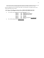
4.1.5
RECORDING ON TWO OR MORE DRIVES
♦ Make sure the two drives are on consecutive SCSI ID numbers i.e., 3 and 4.
♦ Power up the first drive (Turn on the key of the Kingston or insert the cartridge for a removable
media) and wait until it mounts.
♦ Set the compression ratio to the desired value.
♦ Initialize the drive.
♦ Power down the first drive (Turn off the drawer key or eject the cartridge for a removable media).
♦ Power up the second drive (Turn on the drawer key or insert the cartridge) and wait until it mounts.
♦ Set the compression ratio to the same value you have set for the first drive.
♦ Initialize the drive.
♦ Power down the second drive (Turn off the drawer key or eject the cartridge for a removable media).
♦ All the preceding steps are required to make sure that both drives are initialized with the same
compression ratio & recording parameters.
♦ Power up both drives at the same time (Turn the drawer keys or insert the cartridges for removable
media) and wait until they mount.
♦ Set the recording parameters (compression (same as above), time code etc...).
♦ Initialize. Both drives should flash, if not use the Mount menu command to mount all drives; after
mounting both drives should flash during Initialization.
♦ Record. The V1 will start recording on the drive with the higher SCSI ID number and will continue
on the lower ID number. The jump from drive to drive is not noticeable.
This procedure can also be used to record on more than two drives with consecutive SCSI ID
numbers. As described above, each drive must first be initialized alone using the same compression ratio
for all drives, then all drives should be powered-up and initialized together. Use the Mount menu
command to mount all drives, if needed, before initializing them.
4.2
4.2.1
SPECIAL PLAYBACK FUNCTIONS
OPTION PLAY Command or Chase Command
To execute a Chase command, you should hold down the OPTION key (.) and press PLAY. Both the
source machine and the V1 should be synchronized to the same source of House Sync and the time code
should be fed from the source machine into the LTC IN of the V1. Begin playing the source machine.
The V1 will begin playing as soon as it sees time code that is within the range defined for the active drive
and will continue playing in stand alone mode, so a stop on the incoming LTC will not stop the V1.
This Chase command is different from the Chase to LTC mode (See Section 4.2.2, "Chase to LTC", in
that mode, the V1 will stay locked to the incoming LTC). Note that during OPTION PLAY, the V1 LCD
displays PLAY with a black dot to indicate that the play is in sync with the source.
4.2.2
CHASE to LTC Time Code mode
To put the V1 into the "Chase to LTC" mode, change the menu (03) to "Chase to LTC". Both the source
machine and the V1 should be synchronized to the same source of House Sync and the time code should
be fed from the source machine into the LTC IN of the V1. Begin playing the source machine. The V1
will begin playing as soon as it sees time code that is within the range defined for the active drive and
will continue to play LOCKED to the incoming LTC, so a stop on the incoming LTC will also stop the
25
V1. Note that during this chase play, the V1 LCD displays "VAR" to indicate that it can chase at
different speeds.
4.2.3 CHASE to MTC MIDI Time Code mode
Similar to the Chase to LTC mode described above but using the MIDI time code input instead of the
LTC input.
4.2.4
CHASE to RS422 or Serial Time Code mode
This mode requires a special cable described in the "Connecting the V1 to the DD1500" section, Section
10.2.
To put the V1 into the Chase to RS422 or Serial Time Code mode, change the menu (03) to Chase to
Serial TC. Both the source machine and the V1 should be synchronized to the same source of House
Sync and the time code should be fed from the source machine into the RS422 port of the V1. Begin
playing the source machine (DAW). The V1 will begin playing as soon as it sees a time code within the
range defined for the active drive and will continue to play LOCKED to the incoming RS422 timecode.
Note that during this chase play, the V1 LCD displays "VAR" to indicate that it can chase at different
speeds.
NOTE 1 : This Chase mode is only recommended for connecting the V1 to the Akai DD1500. Refer to
Section 10.2, "Connection to the Akai DD1500" for the details of this operation. The V1 can also play in
Chase "to LTC" with the DD1500 but with some limitations in the variable speed range due to current
limitations of the LTC output of the Akai DD1500.
NOTE 2 : Don't put the menu (03) Chase on "RS422" to have a standard RS422 control operation
on the V1. The standard RS422 control is done with menu (03) Chase in the OFF position.
4.2.5
CHASE to BI-PHASE mode
To put the V1 into the Chase to Biphase mode, 3 steps are required :
• First, change the internal cable connector of the second RS422 port to the Biphase position (Refer to
Section 4).
• Second, select the frequency input using Optional Menu (18) "Clks/Frame" (Refer to Section 1.2)..
• Third, change the menu (03) to "Chase to Biphase" and menu (01) to "A-Time" (Refer to Section
1.1).
Both the source machine and the V1 should be synchronized to the same source of House Sync and the
Biphase signal should be fed from the source machine into the second RS422 port of the V1. Locate the
source machine at a reference position, locate also the V1 to the same reference position (frame) and then
enter the required Time code Offset on the V1 (Refer to Section 3.1.4). Begin playing the source
machine. The V1 will begin playing in chase and will continue to play LOCKED to the incoming
Biphase signal, so a stop on the incoming Biphase will also stop the V1. Note that during this chase play,
the V1 LCD displays "VAR" to indicate that it can chase at different speeds.
4.2.6
SEGMENT DEFINITION & PLAYBACK
A segment (also called clip) is a valid recording on the active drive defined by a time in and a time out.
Up to 511 segments can be defined on the V1. To define a segment, press IN where you want the in point
to be and press OUT where you want the out point to be. You may enter these values on-the-fly while
you are playing or you can locate to each point individually (Enter timecode and push GOTO or locate
command on RS422) and enter the in and out points separately. Press SAVE and enter a number from
001 to 511 to identify the segment and then press ENTER. If you want to define the segment that will
play directly after the one you have just entered, before you hit ENTER press the up arrow key and enter
the next segment (you can also define the previous segment) then press ENTER. To recall any defined
segment for playback, press RCL, enter the number of the segment from 001 to 511, and then press
ENTER. The segment will play automatically and the LCD will display the segment information as
indicated in the following section.
CAUTION NOTE : The V1 will not save any segment number above 511 and will also not save
segment number 000.
26
Using version 1.99P and above, when you start to enter the clip number the V1 will immediately locate
to that clip. It will go to play only if you hit ENTER. Example: Recall Clip No. 123 :
1- Push the RCL button, you see recall clip: 000
2- Push 1, the V1 will locate to clip 1.
3- Push 2, the V1 will locate to clip 12.
4- Push 3, the V1 will locate to clip 123.
5- if you hit escape the V1 will remain located at the start of clip 123, if you hit enter the V1 will replay
clip 123.
6- if a clip dose not exist, the V1 will locate to the start of the disk.
4.2.7 DELAYED PROGRAMMING
You can use the V1 loop feature to create a 2 channel delayed programming system. To build this
system you need to have a two channel V1 system, where two V1 units are connected to the same
server with enough storage to equal or exceed the delay desired. Both units should have option
menu (22) Loop Mode ON and option menu (8) Clip Menu to 0 (or the desired playback clip).
Both units should be in A-Time mode.
To prepare the server you need to make sure that menu (10) Time left is equal to 00:00:00:00,
You can achieve that by recording on the whole server at least once or using the Option Menu
Stripe TC command.
•
•
Set Option Menu 12, V1 Type, to Rec/Player on the V1 recorder, then use Option Menu (4)
to save the settings.
Set Option Menu 12, V1 Type, to Player Only on the V1 player, then use Option Menu (4) to
save the settings.
•
Restart the whole system, and after both units mount the server, make sure that Time Left is
equal to 0.
•
Feed the time code output of the V1 reorder to the time code input of the V1 player. Use a
balanced ¼ in. cable (very important).
•
On the V1 recorder locate to the A-Time that equals the delay desired (if your delay is 1 hour
locate to A-Time 01:00:00:00) and start recording.
•
On the V1 player locate to the A-Time that equals the delay desired, then add the delay to that
A-Time (2xDELAY), type the value 2xDELAY using the numeric keypad and hit OPTION
IN. Example: If your delay is 1 hour, locate to 01:00:00:00, type 02:00:00:00 and hit
OPTION IN. If you want to avoid repeating this step every time you turn the V1 player ON,
you can use the Save command to keep the delay saved on the Flash EPROM of the V1
Player.
•
Hit OPTION PLAY on the V1 player to initiate a chase command, the V1 player will start
playing the material recorded a DELAY earlier. If the V1 player does not start playing hit
OPTION PLAY one more time.
This system will stay in a loop until you press stop on both units.
4.2.8
PLAY LIST & LOOPING
Once the segments are fully defined as described above, a play list can be defined to automatically chain
or loop segments during playback. In order to implement this list, each segment requires the definition of
a "next segment" parameter and, optionally, a "previous segment" parameter.
27
To define the next segment :
♦ Press RCL, enter the number of the segment to MODIFY, press , the LCD will display "Next Seg
: sss", enter the segment number of the clip you want to play next and press ENTER. Note that your
are only allowed to enter valid segment numbers. If the current segment is equal to the next segment
then you have defined an infinite LOOP (until you hit STOP).
♦ Do that for each segment you want to chain.
Define a previous segment only when you want to insert a segment into an existing play list.
♦ Press RCL and enter the number of the segment to be inserted, press , the LCD will display "Prev
Seg : sss", enter the segment number that will precede it in the play list and press ENTER. Note that
your are only allowed to enter valid segment numbers.
♦ Press RCL and enter the number of the segment to be inserted, press , the LCD will display "Next
Seg : yyy", enter the segment number that will follow in the play list and press ENTER. Note that
your are only allowed to enter valid segment numbers.
Examples:
To play the following list of segments: (4, 3, 8, 1, 4) the 4 at the end will cause the V1 to loop.
Once all these segments have been defined with the IN, OUT and SAVE:
Press RCL 004
Next Seg
=
003
ENTER
Press RCL 003
Next Seg
=
008
ENTER
Press RCL 008
Next Seg
=
001
ENTER
Press RCL 001
Next Seg
=
004
ENTER
To insert segment 5 in the play list: (4, 3, 8, 5, 1, 4)
Prev Seg
=
008
Press RCL 005
Press RCL 005
Next Seg
=
001
ENTER
ENTER
The "Previous Segment" is only used to insert a segment in a previously defined play list. The V1 will
automatically display the previous segments for each play list item when you recall the segment and
move to "Prev Seg".
Note 1: The segment definition and playback feature allows the user to define more than one play list, as
long as the segment numbers do not conflict. i.e. the user can define: Play list 1: (5, 4, 3, 2, 1, 5)and Play
list 2: (10, 9, 8, 7, 10). To play list 1, the user can recall any segment from list 1 (1, 2, 3, 4 or 5) or play
list 2 by recalling any segment from list 2 (7, 8, 9 or 10).
Note 2: A list can be modified during playback. This is useful to allow jumps from one list to the other.
If we use the 2 play list defined in Note 1, if during playback of list one, the user Recalls segment 2 and
enter 10 as the next segment (instead of 1), the V1 will jump from list 1 to list 2 as soon as it finishes
playing back segment number 2.
Note 3: A segment can also be used as a marker. Locate to the point you want to put a marker on, hit the
IN key followed by the OUT key and save the segment number as "sss" (do not define an OUT point).
Any time you recall segment "sss" the V1 will locate to that point and stops.
Note 4: The Segment definition uses the A-Time as a reference, this means that even if you set a Time
Code Offset, your segments will not change, they will only display the new time code when played.
4.2.9 REMAINING TIME OF A SEGMENT DURING PLAYBACK
When you RECALL a segment or a play list, the LCD will display the segment number playing back
along with the remaining time up to the OUT point of that segment in the following format:
sss :
MM.SS
Where sss is the segment number played from 001 to 511 and MM.SS is the remaining time up to the
OUT point in mn:sec.
28
4.2.10 REVERSE PLAY
To play video and audio in reverse at normal speed, hold the OPTION key (.) and press REW. You may
also press the WHEEL button and go into SHUTTLE at the same reverse play speed.
During reverse play, the LCD will display : " << 100%
JOG ".
4.3
4.3.1
USING DISCONTINUOUS TIME CODE ON A DRIVE.
INCREASING TIME CODE
If your drive is divided for example into 3 different projects, where the first project on the
recorded on the drive goes from 01 00 00.00 to 01 10 00.00, the next from 02 00 00.00 to 02 15
00.00 and the third from 03 00 00.00 to 03 12 00.00, you can switch between projects just by
locating to any time code location within the destination project.
4.3.2 NON INCREASING TIME CODE
If your drive is divided for example into 3 different projects, where the first project on the
recorded on the drive goes from 02 00 00.00 to 02 15 00.00, the next from 01 00 00.00 to 01 10
00.00 and the third from 03 00 00.00 to 03 12 00.00, you can switch between projects using two
different methods:
♦ Use the REW or FF until you get to the destination project.
♦ Define a segment for each project and select the desired project from the Clip Menu.
4.3.3
REPEATING TIME CODE
If your drive is divided for example into 3 different projects recorded using the same time code,
you can switch between projects using two different methods:
♦ Use the REW or FF until you get to the destination project. The only way you would recognize the
project is by looking at the video because the LCD display will give you the same time code for all
three project. Not recommended.
♦ Define a segment for each project and select the desired project from the Clip Menu.
29
5 REAR PANEL CONNECTIONS
Analog Audio
These XLR connectors are the balanced analog audio inputs and outputs.
Pin 2 is hot (+), pin 3 is cold (-), and pin 1 is ground.
Digital Audio
Optional on the V1 and V1b and standard on the V1D. Transformer
balanced AES/EBU input and output. Pin 2 is hot (+), pin 3 is cold (-),
and pin 1 is ground.
RS-422 (1)
The serial interface connector to the V1. Connector 1 should be
connected to your edit controller or workstation, while connector 2 is
used to connect the optional RCV1 external remote control from Doremi
Labs, Inc.
RS-422 (2) or Biphase
If the internal cable of RS-422 connector-2 is installed on J10 of the
main motherboard, this port can be used as a second RS-422 connector.
It can then be used to connect the optional RCV1 external remote
control from Doremi Labs, Inc. If the internal cable of RS-422
connector-2 is installed on J3 of the main motherboard, this port can be
used as the Biphase input connector. Refer to Section 4.1, "Hardware
setup of the Biphase Input".
J1
DIP switches for selecting the SCSI ID of the V1. See Section 0, "DIP
Switch Settings".
Time Code
Balanced TRS 1/4" input and output connectors for LTC time code. The
V1 time code input accepts balanced signals (tip hot, ring cold & sleeve
is ground). If you are feeding an unbalanced signal to it, both ring and
sleeve should be connected to GND. You can use an unbalanced jack
(tip and sleeve) on the time code input of the V1. The V1 time code
output is a balanced signal (tip hot, ring cold & sleeve is ground). If you
are feeding it to an unbalanced input, ring should not be connected to
anything. You can not use an unbalanced jack (tip and sleeve) on the
time code output of the V1. If you connect time code from one V1 to
the other the cable should be balanced on both ends.
Sync In
House Sync input BNC connector for the V1 synchronization reference.
Use only Black Burst Sync here. Your Sync input should not exceed 1V
P-P.
Video
Analog Composite video input and output BNC connectors. Video IN is
where you connect your video signal for recording to the V1 and Video
OUT is for connection to a video monitor or another video recorder.
S-Video
SDI
RGB/YUV
SCSI
Mini DIN-4 connectors for S-Video (Y/C) input and output.
V1D only. Serial Digital Interface input and output BNC connectors for
a direct connection with digital betacams.
V1D only. Three RGB or YUV selectable BNC output connectors
Standard 50-pin female Centronics connector for connection to external
SCSI drives. When no external SCSI devices are used, make sure the
supplied terminator is connected here. When connecting external drives,
30
the last drive in the chain should be terminated. All V1 internal drives
supplied by Doremi Labs, Inc. are non-terminated.
VITC Out
MIDI
Ethernet
115V/230V
Available only on units with serial number 201 or higher.
DIN 5 connectors for MIDI chase.
RJ45 connector 10BT
Confirm that the proper voltage is selected for your area on the power
supply. The switch is located between the power connectors.
Note : On the V1D, please do not use YUV/RGB output and Y/C (S-Video) outputs at the same time
because these signals are coming from the same buffered outputs and so this will produce a mismatch on
impedance loads.
5.1
HARDWARE SETUP OF THE BI-PHASE INPUT
The Biphase input connector (9 pin D-Sub) is wired as follows :
Pin
1
2
3
4
5
6
7
8
9
Signal
Not connected
Ground
RZ input (0 to +5V)
Not connected
output +5V
ground
SZ input (0 to +5V)
not connected
ground
In order to enable the Biphase input port : switch off the V1, disconnect the AC power cable, remove
the V1 top cover and locate the IDC10 ribbon cable connected to the second RS-422 connector. Unplug
the IDC connector from J10 on the motherboard and plug it on J3 (the red mark or pin1 should be to your
left if you are looking straight at the front panel of the V1).
Note : The RZ and SZ signals are locked in phase with a +/-90° phase difference.
31
6 VToolsPro Utility Software
VToolsPro is a software utility that displays a V1 front panel on a Mac or a PC running Windows 98,
Windows NT 4.0 or Windows 2000 and performs the same operations of the V1 front panel. VToolsPro
had originally been developed for the V1b video recorder/player (V1 without front panel controls &
display), but can also be used with the V1 as a remote utility.
6.1
VToolsPro Installation
♦ Unzip the file called VTProxxx.zip (expand VTProxxx.sit for a Mac) in one directory. xxx
designates the version number of the program
♦ For a PC, connect the bottom RS422 port of the V1 to a free serial port on your PC (Com 1 to 4) by
using the V1 RS422-PC cable (description available at the end of this chapter). This cable allows a
direct connection from the PC RS232 port up to the RS422 port of the V1.
♦ For a Mac, connect the bottom RS422 port of the V1 to a free serial port on your Mac (Modem or
Printer) by using the V1 RS422-MAC cable (description available at the end of this chapter).
♦ Run the VToolsPro utility.
♦ A window will appear showing the V1 front panel; if the V1 has a valid drive with video recorded,
the time-code display in the VToolsPro window will show the V1 time-code.
IN ORDER FOR VTOOLSPRO TO RUN PROPERLY, YOU NEED TO HAVE THE FILE "v1s.cfg" IN
THE SAME DIRECTORY AS THE APPLICATION VTPROxxx.
WINDOWS 95 USERS: If you get a message that the file WS2-32.dll is missing, you need to copy the
two files enclosed in the "WS2.zip" in the "windows\system" directory. You will find "WS2.zip" on our
ftp site at ftp://www.doremilabs.com. WE NO LONGER SUPPORT WINDOWS 95.
6.2
Editing the configuration file v1s.cfg
Before running VToolsPro, you need to configure the file v1s.cfg to match your hardware. The file is
already pre-configured to use COM1 and COM2 on a PC and both Modem and Printer ports on a Mac.
The first block of information specifies the communication ports used by VToolsPro. Each
communication port has its own definition information formatted as follows:
CMMx
NNNN
communication port identification field.
CMM0 is the first serial port.
CMM1 is the second serial port.
CMM2 is the Ethernet port.
number of V1s connected to this port should be 4 characters long with leading zeros.
The field structure for each V1 connected to this port is:
ssssss
IIIIIIII
PPPP
serial number in decimal of the V1. This serial number should be six characters long
with leading zeros.
IP address of the V1 in Hex.
UDP port of the V1 in Hex (default 8080).
NEXT V1 or NEXT communication port identification
.
.
A last line that reads ‘endf’ should indicate the end of the useful information.
Note: If you get a TCP/IP warning message, you can either install TCP/IP on your computer or
just hit OK and ignore the message. In the second case the software would still function normally
32
on any of the serial ports. The only way to get rid of the TCP/IP startup message is by installing
TCP/IP on your computer
6.3
VToolsPro Menus
File
New: New Clip File
Open: Open an existing Clip File
Save: Save current clip file
Save As: Save current clip file with a different name
Import clips from V1: Import clips from the V1
Export play list to V1: Exports the active play list to the V1. If the loop button is pressed,
the play list will be looped.
Export clip list to csv: Exports the clip list to a csv file
Export play list to csv: Exports the play list to a csv file
Quit: Quit the program
Edit
Undo: Undo the last change
Cut Clip: Cut the selected clip to the clipboard
Copy Clip: Put the selected clip in the clipboard
Paste Clip: Paste clip from the clipboard
Find: Find the clip in the list
Clip
In: Set the IN point of the clip to be created
Out: Set the OUT point of the clip to be created
Create Clip: Create a new clip using the IN and OUT points
Rename Clip: Rename the selected clip
Goto In: Go to the IN point of the selected clip
Goto Out: Go to the OUT point of the selected clip
Open Source: Open the Source clip file to be copied
Copy to Time Line: Copy the source file to the destination disk at the time line location
Copy to End: Copy the source file to the destination disk at the end of the disk.
Rename Disk…: Rename the V1 disk
Command Goto…: To locate to a specific time code, enter the value in the format hhmmssFF.f. To
locate to 23 minutes 12 seconds 15 frames field 2 enter: 00231215.2 (the 00 at the start is not
necessary).
Set TC…: To create an offset, enter the desired time code at the current time line and hit
OK.
SCSI Copy…: Select your source and destination drives for a full disk copy
SCSI Continue Copy…: Continue the SCSI copy from where you have stopped it.
Get Field From…: Capture a field and display it in the View Mode.
SCSI: Capture the field through SCSI
Ethernet: Capture a field through Ethernet
File: Capture a field from a JPEG File
Save Field: Save the current field to a standard JPEG file. Get field should be executed
before this command
Save V1 Field to File: Save the current field to a non-standard JPEG file. This file can only
be used on the V1XServer
Get Movie: Not Used anymore. Refer to Vconvert.
Escape: TBD
Send P2 message: send a hex S9P message to the V1 through the active connection. Every
byte (2 digits) should be separated by a “.”. You should no add the checksum to the message,
VToolsPro will calculate it automatically.
Control
Control V1 on: Choose the port connected to your V1
Help
About VToolsPro Information about the version number of the software.
33
6.4
VToolsPro Modes of operation
Control: Use this mode to control the V1
Clips: Use this mode to manipulate clips
Copy: Use this mode to make a SCSI copy of a clip list
View: Use this mode to capture a field from the V1 on your computer screen
6.4.1 VToolsPro Controls
When you run the VToolsPro application, the first tab “CONTROL” will be the active window
RR
Rewind button with a speed of 40 times normal. When the rewind is
close to the beginning of the recording, the speed is slowed down to
normal until it reaches the start.
FF
Fast forward control button with a speed of 40 times normal. When the
fast forward is close to the end of the recording, the speed is slowed
down to normal until it reaches the end.
PLAY
Play control button: If the active drive has recorded material, pressing the
PLAY key will start playback from the current location at normal speed
and the green LED will go ON.
STOP
Stop control button: The STOP key will cause the V1 to stop any
transport control (play, record, rewind, and fast forward).
REC
Record control button: This key is used in several ways, all described
earlier in this manual.
LOCK
This button locks PLAY and REC together. If LOCK is highlighted,
pressing PLAY will be like pressing PLAY and REC at the same time.
(Option) MENU
Pressing MENU will engage the menu mode. Pressing the MENU key
again will return the V1 to the time code display mode. (You may also
press ESC). All settings are saved. Holding down the Option (ALT for
PC) key of the keyboard and pressing MENU will engage the Optional
Menu mode.
UP
DOWN
Use this key ( ) to scroll to the next menu.
Use this key ( ) to scroll to the previous menu.
34
TGL
NUDGE BACK (--)
NUDGE FORWARD (++)
Locates one field back from the current position. Also used for selection
in the "Edit Preset" and "Set Video" Optional Menu selections.
Locates one field ahead of the current position. Also used for selection
in the "Edit Preset" and "Set Video" Optional Menu selections.
SHUTTLE
Click on the button and move the mouse to shuttle in forward or reverse.
The angle, up to +/-90°, controls the shuttle speed, which is displayed on
the second line of the LCD. When the mouse button is released, the
shuttle button will return to its original position (0°)
IN
Sets the IN point for segment play. (See Section 4.2.6, "Segment
Definition and Playback").
OUT
Sets the OUT point for segment play. (See Section 4.2.6, "Segment
Definition and Playback").
GOTO
To locate to a specific frame (field) from the V1 front panel, enter the
time code location numbers from the numeric keypad and press GOTO.
ESC
This is the escape key. Press it when you want to exit the menu mode or
abort an operation.
RCL
Used to recall segment numbers (See Section 4.2.6, "Segment Definition
and Playback").
SAVE
Used to save a segment to a memory location number. (See Section 4.2.6,
"Segment Definition and Playback").
AT/TC
REMOTE/LOCAL
Option _RR
6.4.2
Use this key to change selections within most menus.
Toggles between Absolute Time and Time Code.
Toggles between Remote and Local.
Holding down the Option (Shift for PC) key of the keyboard and
pressing the RR button allows the V1 to play in reverse at normal speed.
VToolsPro Clips
Clicking on the second tab “CLIPS” will take you to the clip window.
35
On the left is the list of clips.
On the right is the play list.
To create a clip, go to the in point and click on "in", go to the out point and click on "out", then click on
"clip". If you double click on any of the time location in the clip list, the V1 will locate to that time.
To create a play list, click "->" or "-> /" to insert a clip in the play list. To remove a clip from the play
list, select it and click on "<-". To clear the play list, click on "<- ALL". To play a play list, double click
on the first clip, the machine will automatically chain until the end. If you want to loop the playlist
playback, click on the “loop” button (click again to cancel the loop). During the execution of a play list
you can jump to the next clip by pressing the "next" button, or jump to the previous clip by pressing
"prev" button.
Other useful clips commands available from Menu:
Edit
Undo: Undo the last change
Cut Clip: Cut the selected clip to the clipboard
Copy Clip: Put the selected clip in the clipboard
Paste Clip: Paste clip from the clipboard
Find: Find the clip in the list
Clip
In: Set the IN point of the clip to be created
Out: Set the OUT point of the clip to be created
Create Clip: Create a new clip using the IN and OUT points
Rename Clip: Rename the selected clip
Goto In: Go to the IN point of the selected clip
Goto Out: Go to the OUT point of the selected clip
Rename Disk…: Rename the V1 disk
Once a list of clips &/or play list is done, it is better to save it on your PC/Mac drive using the File Menu:
File
New: Open a new empty file and clears the clips in the V1
Open: Open an existing clip & play list file
Save: Save current clip & play list file
Save As: Save current clip & play list file with a different name
Import Clips: Import existing clips from the V1
Quit: Quit the program
If the V1 mounted drive has already clips defined, you can get them by selecting Import Clips in the File
Menu, then save them locally on your PC/Mac using Save or Save As
WARNING : IF YOU HAVE CLIPS IN THE V1, YOU SHOULD IMPORT THEM FIRST AND
SAVE THEM INTO A FILE, OTHERWISE, THE SOFTWARE MIGHT ERASE THEM !
ALSO SELECTING MENU FILE, NEW WILL AUTOMATICALLY CLEAR ANY EXISTING
CLIPS IN THE V1 !
Once your PC/Mac drive has valid clip/play list files saved, you can open them and automatically
upload them to the V1 connected by selecting Open in the File Menu
36
Keyboard command equivalence:
Command N: New
Command O: Open
Command S: Save
Command Q: Quit
Command X: Cut
Command C: Copy
Command V: Paste
Command F: Find
Command I: Set 'In'
Command J: Set 'Out'
Command T: "Create Clip'
Command G: Go To
Space bar: Start/Stop
up Arrow: Select Previous Clip
down arrow: Select next clip
option up arrow: Select previous clip in play list
option down arrow: Select next clip in play list
option right arrow: insert selected clip in the play list after
option control right arrow: insert selected clip in the play list before
option left arrow: remove selected clip from the play list
option control left arrow: remove all clips from the play list.
6.4.3
VToolsPro Copy (add clips to existing material)
The COPY tab will show:
This is the (active/mounted) destination disk clip list
This is the source (unmounted) disk clip list
You need to have two removable drives using different SCSI Ids and using the same compression ratio.
The original clips are on the “source disk”, the clips will be copied to the “destination disk”.
37
1. Power up the source disk and create all the clips that you intend to copy to the destination disk.
These clips should appear on the clip list of the VToolsPro application
2. Save the clip list file on your PC using the Save Command for the File Menu.
3. Power Down the source disk and wait until you see the No Disk message.
4. Power Up the destination disk and wait until the No Disk message disappears.
5. Open the clip list file for the destination disk or import the existing clips.
6. Locate the time line on the destination disk to the position you want to start your copy at
7. Power up the source disk and wait for 1 minute (allow enough time for the drive to spin up, the V1
will not give any indication that the source disk is ON)
8. Click on Source and select the clip list file you have previously saved. The bin will now show all the
clips under the Source tab.
9. Select the SCSI ID of the source drive. Keep lun at 0
10. Select the clip you want to copy from the bin and hit “copy-> TL”. This will copy the clip selected at
the time line location of the destination disk. If you want to copy to the end of the drive, you can hit
“copylast” instead of “copy-> TL”
6.4.4
VToolsPro View
Command
6.5
Get Field From…: Capture a field and display it in the View Mode.
SCSI: Capture the field through SCSI
Ethernet: Capture a field through Ethernet
File: Capture a field from a JPEG File
Save Field: Save the current field to a JPEG file
Get Movie: Not Used. Refer to Vconvert
SCSI Copy using VToolsPro
We do not recommend using this function. Refer to Vconvert
6.6
The Ethernet Option
To take full advantage of the Ethernet board you need to follow these steps:
If you received the Ethernet Option with your unit, you can read the factory assigned IP address by going
to the Version Optional Menu and hitting the Toggle Key. If that IP address is OK with your network
administrator, you can proceed to step B. below, otherwise start from 1.
1. Connect the serial cable between your V1 and the PC or MAC. Make sure the Ethernet is not
connected at this time
2. Run Vupdater (refer to Chapter 7 The Vupdater Utility), and select the connected serial port from the
“Connect” menu.
38
3. Enter an IP address in decimal for that V1 using the following convention:
Enter 10.1.1.80 for the first V1 unit with an Ethernet board
Enter 10.1.1.81 for the second V1 unit with an Ethernet board
.
.
Etc.
4. For network mask, leave the default value 255.255.255.0 if you are not sure what else to put.
5. For port address, leave the default value 128.128 if you are not sure what else to put.
6. Enter the serial number of the V1 unit
7. Select the proper mainxxxx.bin and hit “Download”.
Note: The Ethernet only works with V1 software version 1.99u or higher
The V1 will start the update procedure, after the message "Success" is displayed, turn off the V1, and
wait until the drives have settled and restart the V1. The version number might not appear at startup, but
you can see it from the option menu by going to option menu 00 and hitting the down arrow key.
Now you need to prepare your v1s.cfg file to use Ethernet equipped V1s.
A.
B.
C.
D.
E.
F.
G.
H.
I.
J.
Quit Vupdater
Make sure VToolsPro and v1s.cfg are in the same folder
Open the file v1s.cfg with a text editor
If the lines starting with “CMM2” down to “endf” are commented using “#”, you need to remove the
“#” from the beginning of all the lines, starting with CMM2.
Under CMM2 you need to enter the number of V1s with Ethernet, the serial number and the IP
address of every V1 according to the following :
CMM2
NNNN: indicates the number of V1s with Ethernet
SSSSSS: indicates the serial number of the first V1. Enter your own here in decimal.
0A010150: indicates the IP address of the first V1 in hexadecimal (10.1.1.80)
PPPP: indicates the port used in hexadecimal (8080HEX=128.128DECIMAL)
TTTTTT: indicates the serial number of the second V1. Enter your own here in decimal
0A010151: indicates the IP address of the second V1 in hexadecimal (10.1.1.81)
PPPP: indicates the port used in hexadecimal (8080HEX=128.128DECIMAL)
.
.
.
endf
ends the Ethernet port
Save the file v1s.cfg as text and keep the same name and extension "v1s.cfg"
Disconnect the serial cable connecting the V1 to your computer
Connect all V1s with Ethernet to the same 10BT hub or switch your computer is connected to.
Run VToolsPro
Go to the menu "Control" and choose "Connect V1 on" a pop up menu will show you
Com1
Com2
Ethernet-SSSSSS (The first serial number in v1s.cfg will appear here)
Ethernet-TTTTTT (The second serial number in v1s.cfg will appear here)
If you select any of the Ethernet lines, the unit with the same serial number will become the
controlled unit.
A properly configured “v1s.cfg” file for use with 2 V1s with Ethernet Option would look like:
CMM0
0001
000000
00000000
0000
CMM1
0001
0000
00000000
39
0000
CMM2
0002
000999
0A010150
8080
0002
001000
0A010151
8080
endf
The Ethernet board can be installed on all V1 units with serial number 200 or higher, the Ethernet board
sits in place of the MIDI board. By installing the Ethernet board both MIDI and Biphase will be disabled.
Note: On you computer you need to enable TCP/IP via Ethernet and configure your server with an IP
address and a Subnet Mask (consult your network administrator to get a unique IP address for your
computer). A common Subnet Mask is 255.255.255.0.
Note: Installing the Ethernet option will disable MIDI and Biphase on the V1.
Contact your local dealer to order the Ethernet board upgrade.
6.7
Command Prompt Functions for the PC version:
On the PC, you can execute any s9p command from the DOS prompt through the Ethernet
connection to the V1. These command do not work with a serial connection. The format is:
VTProxxx N IP1 IP2…IPN s9p SSSS D0 D1 D2 …
xxx: Version number of VToolsPro
N: Number of V1 units that will receive the same s9p command
IP1 IP2..IPN: IP addresses of the V1 units that will receive the same s9p command
s9p: Case sensitive. Indicates that the following string is a Sony 9pin command in hex
SSSS: Sony 9pin command (all 4 digits should be together. No Space between bytes)
D0: Data 0 byte
D1: Data 1 byte
etc..
To send a play command:
VTPro220 1 10.1.1.191 s9p 2001
To send a RESET command:
VTPro220 1 10.1.1.191 s9p 3409 41 53 41 50
One more function is available through the command prompt:
VTProxxx 1 IP savefield name.jpg
xxx: Version number of VToolsPro
1: Only 1 unit can receive this command
IP: IP address of the unit
savefield: Case sensitive. Indicates that the operation is saving a JPEG field on the PC
name.jpg: JPEG file name in the same directory of Vconvert.
Example: VTPro220 1 10.1.1.191 savefield fruit.jpg
40
7 The Vupdater Utility
Vupdater is a new utility that should be used to update the internal software of the V1 line of products.
YOU SHOULD NOT USE ANY PREVIOUS VERSION OF V-TOOLS OR V-TOOLS PRO TO
UPDATE YOUR V1 SOFTWARE. BY USING ANY OTHER UTILITY YOU ARE RISKING AN
UNSUCCESSFULL UPDATE THAT MIGHT RESULT IN PHYSICALLY CHANGING THE FLASH
EPROM ON YOUR UNIT.
WINDOWS 95/98 USERS, SEE THE NOTE AT THE END OF THIS CHAPTER.
Select from list which firmware version you want to upload
Enter desired V1 IP address
Enter V1 S/N (See rear panel)
PLEASE READ AND FOLLOW CAREFULLY IN ORDER TO UPGRADE CORRECTLY
The Vupdater utility is a self contained application that does not require any other components to run
except on Windows 95. If you get a message that the file WS2-32.dll is missing, you need to copy the
two files enclosed in the "WS2.zip" in the "windows\system" directory. You will find "WS2.zip" on our
ftp site at ftp://www.doremilabs.com.
1. Unstuff (unzip) all the files contained in the MAINxxxx.sit (MAINxxxx.zip) into the same folder
with the Vupdater utility.
2. Connect the bottom RS422 port of the V1 to your computer
3. Turn ON the V1, wait until the drive mounts, and check that a correct video signal is displayed on the
V1 monitor.
4. Open the Vupdater folder and start Vupdater by double clicking on its icon. Click on the “Connect”
menu and select the port connected to the V1 unit. If a communication is established, the Vupdater
window should display the same time code shown on the V1 front panel, click on PLAY then STOP,
and confirm that the V1 responded properly to your commands.
5. If you have the Ethernet option on your V1, type the desired IP address in the designated field.
6. Type the serial number of your unit in the designated field.
7. Select the file to download, i.e. "mainxxxx.bin" and hit the “Download” button. The update
procedure will begin. You should see "Uploading...", then "Flashing...", then "Success..." (Note
that while "Flashing...", the video frame might be erased).
41
8. Once "Success..." is displayed, you can quit Vupdater and turn off the V1.
9. Restart the V1, and check the version number, which, in this case, should be "Vx.xx". This will
confirm that the upgrade was successful.
IMPORTANT NOTE FOR WINDOWS 95/98 USERS WITH V1 VERSION < 2.xx :
WINDOWS 95/98 USERS MIGHT HAVE A PROBLEM UPDATING THEIR UNITS FROM 1.99Z OR
ANY LOWER UP TO 2.XX. THE ONLY SOLUTION TO THIS PROBLEM IS BY USING AN
OLDER VERSION OF V-TOOLS CALLED V1TOOLS (DO NOT USE ANY VTOOLSPRO). THIS
UTILITY SHOULD ONLY BE USED ONCE TO GO UP FROM 1.99Z OR ANY LOWER VERSION
UP TO 2.XX. AFTER THE V1 HAS VERSION 2.XX, THEN USE ONLY THE VUPDATER UTILITY
TO UPGRADE TO HIGHER VERSION NUMBERS.
YOU CAN FIND V1TOOLS AT: ftp://www.doremilabs.com/v1tools.exe
42
7.1
Wiring of the V1 RS422-PC Cable
CONTROLLING DEVICE
(PC/RS232)
DB9-F
Front View
5
4
9
3
8
1
2
7
6
1
2
6
3
7
4
8
5
9
CD
1
1
Frame GND
RXD
2
2
TXA
TXD
3
3
RXB
DTR
4
4
RX_GND
GND
5
5
SPARE
DSR
6
6
TX_GND
RTS
7
7
TXB
CTS
8
8
RXA
RI
9
9
Frame GND
Shell
Wiring List:
CONTROLLED DEVICE
(V1)
DB9-M
Front View
Shell
V1 (1) to V1 Shell to PC Shell
V1 (2) to PC (2)
V1 (8) to PC (3)
V1 (3 + 4 + 6) to PC (5)
Note: For a true RS422 connection, you can use an adapter made by KK Systems (Part Number
K422-99). This adapter connects to the RS232 port on the PC and provides an RS422 connection
on the other side. To connect the K422-99 to the V1, use a standard RS422 cable (See wiring of
the standard RS422 cable). A true RS422 connection allows for a better connection and longer
cables.
43
7.2
Wiring of the V1 RS422-Mac Cable
V1 DB9-M
Front View
Mac DIN8-M
Front View
6
3
7
4
1
1
8
2
6
5
3
7
2
TX+
6
3
RXB
TX-
3
8
RXA
RX+
8
7
TXB
RX-
5
2
TXA
SIG GND
4
6
TGND
SIG GND
4
4
RGND
1
Frame GND
Frame GND
4
8
5
9
44
7.3
Wiring of the standard RS422 Cable
CONTROLLING DEVICE
(RCV9P-V1)
DB9-M
Front View
1
2
6
3
7
4
8
1
RXA
2
TXB
3
CONTROLLED DEVICE
(V1)
DB9-M
Front View
1
5
9
2
6
Frame GND
3
7
4
8
5
9
1
2
TXA
Receive B
3
RXB
4
GND
4
5
SPARE
5
6
GND
6
RXB
7
Transmit B
7
TXB
TXA
8
Receive A
8
RXA
9
Frame GND
9
45
7.4
Wiring of the RS422 Chase cable
CONTROLLING DEVICE
CONTROLLED DEVICE
(V1)
DB9-M
Front View
DB9-M
Front View
1
2
6
3
7
4
8
1
1
5
9
2
6
Frame GND
3
7
4
8
5
9
1
Receive A
8
2
Transmit A
Transmit B
7
3
Receive B
Transmit GND
6
4
Receive GND
5
SPARE
5
Receive GND
4
6
Transmit GND
Receive B
3
7
Transmit B
Transmit A
2
8
Receive A
9
Frame GND
9
46
DIP SWITCH SETTINGS
Viewing the V1 from the rear panel, the switches are counted from left to right with 0 (off) being toward
the top of the unit and 1 (on) being toward the bottom. The switches are as follows:
THE DIP SWITCH SETTING SHOULD NOT BE CHANGED WHILE THE UNIT IS ON. THIS
MIGHT CAUSE SEVERE INTERNAL DAMAGE TO THE UNIT AND VOID THE
WARRANTY.
1
(Up)
OFF (0)
ON
(1)
3
4
5
(6)
ID0
(Down)
2
ID1
ID2
(6)
(6)
ON
ON
ONLY
6
7
8
9
10
PAL/
NTSC
Full
720
2 Field
Off
NTSC
-8 pixels
360
1 Field
AFTER YOU UPDATE TO VERSION 2.0, TURN THE UNIT OFF, SET THE DIP SWITCH TO
THE DEFAULT SETTING ABOVE (BOLD) AND RESTART THE UNIT.
•
•
•
•
Switches 1, 2, & 3 set the SCSI ID. These are as follows:
ID0 (Switch 1)
ID1 (Switch 2)
ID2 (Switch 3) SCSI ID Number
Up
Up
Up
0
Down
Up
Up
1
Up
Down
Up
2
Down
Down
Up
3
Up
Up
Down
4
Down
Up
Down
5
Up
Down
Down
6 (default)
Down
Down
Down
7 Test Mode do not use
Switch 4 is termination for the SCSI bus and the default setting is ON.
Switch 5 is for providing termination power, the default setting is ON (provide termination power).
Switch 6 if this switch is in the UP position (recommended setting), the unit can be set to PAL or
NTSC using OPTION MENU (13). If this switch is in the DOWN position, the unit will stay in
NTSC mode and it will not be possible to change it using OPTION MENU (13)
IF YOUR UNIT HAS VERSION 1.99 OR HIGHER, POSITIONS: 1, 2, 3, 6, 7, 8, 9 AND 10 ON
THE DIP SWITCH ARE NO LONGER VALID AND MUST ALL BE SET IN THE UP
POSITION WHILE THE UNIT IS POWERED DOWN. POSITIONS 4 AND 5 SHOULD BE SET
IN THE LOW POSTION TO INSURE PROPER TERMINATION TO THE SCSI BUS
•
•
•
Switch 7 reduces the image size by 8 pixels on all sides. Since standard video monitors do not
display an entire video image, this 10% screen reduction improves the displayed image quality as
there is more disk space available for storing the actual displayed image with less compression. The
default setting is Full (OFF).
Switch 8 selects recording at 360 pixels (horizontal) or 720 pixels (horizontal.) Recording at 360
pixels (horizontal) improves the image quality at high compression ratios (20:1 - 34:1) The
default setting is for recording 720 pixels.
Switch 9 selects recording of 2 fields per frame (CCIR-601) or 1 field per frame. Recording
at 1 field per frame allows you to record approximately twice as much video material on a
disk for any given amount of storage space. The default setting is 2 fields per frame.
SINCE ALL DIP SWITCH SETTINGS ARE NOW MOVED TO THE OPTION MENU,
NEWER UNITS DO NOT HAVE THE DIP SWITCH ON THE REAR PANEL.
47
8 DISK RECORD TIMES FOR VARIOUS COMPRESSION RATIOS
As a typical guide for ratios versus visual quality : 7:1 is comparable to analog Betacam, 12:1 to
16:1 is comparable to S-VHS, 24:1 to 34:1 is comparable to VHS. For typical audio postproduction work, a 20:1 / 1 field is a good enough visual quality (34:1 / 1 field can also be used
for maximum recording time).
48
8.1
Comp
Ratio
2:1
2.5:1
3:1
3.5:1
4:1
5:1
6:1
7:1
8:1
9:1
10:1
12:1
14:1
16:1
20:1
24:1
34:1
1 GB
1:37
2:00
2:19
2:46
3:17
3:48
4:31
5:09
6:01
6:34
7:13
8:02
9:02
10:19
12:03
14:27
18:04
8.2
Comp
Ratio
2:1
2.5:1
3:1
3.5:1
4:1
5:1
6:1
7:1
8:1
9:1
10:1
12:1
14:1
16:1
20:1
24:1
34:1
1GB
1:37
2:15
2:37
2:57
3:20
3:56
4:33
5:04
5:47
6:40
7:13
8:40
9:38
10:50
12:37
14:27
17:21
NTSC Compression Chart according to CCIR-601
RECORDING TIME FOR NTSC 2 FIELDS/FRAME
2 GB 2.6
4 GB
9 GB
18GB
36GB
GB
3:02
3:26
6:54
13:49
27:38
0:55:16
3:45
4:18
8:33
17:08
34:16
1:08:32
4:22
5:00
9:56
19:54
39:48
1:19:36
5:13
5:58
11:51
23:44
47:28
1:34:56
6:09
7:59
13:13
28:03
56:06
1:52:12
7:08
9:15
15:18
32:28
1:04:56 2:09:52
8:28
10:59 18:11
38:34
1:17:08 2:34:16
9:41
12:33 20:46
44:05
1:28:10 2:56:20
11:17 14:38 24:14
51:25
1:42:50 3:25:40
12:19 15:58 26:27
56:06
1:52:12 3:44:24
13:33 17:34 29:05
1:01:42 2:03:24 4:06:48
15:03 19:31 32:19
1:08:34 2:17:08 4:34:16
16:56 21:57 36:22
1:17:08 2:34:16 5:08:32
19:22 25:06 41:34
1:28:10 2:56:20 5:52:40
22:35 29:16 48:29
1:42:51 3:25:42 6:51:24
27:07 35:08 58:11
2:03:25 4:06:50 8:13:40
33:54 43:55 1:12:44 2:34:17 5:08:34 10:17:08
50GB
74GB
1 GB
RECORDING TIME FOR NTSC 1 FIELD/FRAME
2GB
2.6 GB 4 GB
9 GB
18GB
36GB
50GB
74GB
1:16:46
1:35:11
1:50:33
2:11:51
2:35:50
3:00:22
3:34:16
4:04:54
4:45:39
5:11:40
5:42:47
6:20:56
7:08:31
8:09:49
9:31:23
11:25:39
14:17:08
1:50:32
2:17:04
2:39:12
3:09:52
3:44:24
4:19:44
5:08:32
5:52:40
6:51:20
7:28:48
8:13:36
9:08:32
10:17:04
11:45:20
13:42:48
16:27:20
20:34:16
3:09
3:54
4:30
5:21
6:17
7:13
8:30
9:38
11:07
12:03
13:08
14:27
16:04
18:04
20:39
24:06
28:55
5:56
7:20
8:28
10:02
11:47
13:33
15:56
18:04
20:52
22:35
24:39
27:07
30:08
33:54
38:45
45:12
54:15
2:30:11
3:05:17
3:34:10
4:13:53
4:58:03
5:42:47
6:43:20
7:37:08
8:47:30
9:31:23
10:23:20
11:25:39
12:41:51
14:17:08
16:19:38
19:02:52
22:51:23
3:36:16
4:26:48
5:08:24
6:05:36
7:09:12
8:13:36
9:40:48
10:58:16
12:39:36
13:42:48
14:57:36
16:27:20
18:17:04
20:34:16
23:30:40
27:25:44
32:54:48
6:48
8:23
9:42
11:30
15:16
17:34
20:40
23:25
27:01
29:15
31:55
35:07
39:01
42:55
50:11
58:31
1:10:15
13:30
16:40
19:16
22:50
25:18
29:05
34:13
38:47
44:45
48:29
52:53
58:11
1:04:39
1:12:44
1:23:07
1:36:58
1:56:22
27:02
33:21
38:33
45:42
53:39
1:01:42
1:12:36
1:22:17
1:34:57
1:42:51
1:52:12
2:03:25
2:17:08
2:34:17
2:56:20
3:25:43
4:06:51
54:04
1:06:42
1:17:06
1:31:24
1:47:18
2:03:24
2:25:12
2:44:34
3:09:54
3:25:42
1:44:24
4:06:50
4:34:16
5:08:34
5:52:40
6:51:26
8:13:42
1:48:08
2:13:24
2:34:12
3:02:48
3:34:36
4:06:48
4:50:24
5:29:08
6:19:48
6:51:24
7:28:48
8:13:40
9:08:32
10:17:08
11:45:20
13:42:52
16:27:24
PAL Compression Chart according to CCIR-601
RECORDING TIME FOR PAL 2 FIELDS/FRAME
2GB 2.6GB
4GB
9GB
18GB
36GB
3:02
3:41
4:24
5:04
6:15
7:23
8:33
9:29
10:50
12:31
13:32
16:16
18:04
20:19
23:15
27:06
32:33
3:28
5:30
6:21
7:11
8:06
9:35
11:05
12:13
14:03
16:13
17:33
21:05
23:25
26:21
30:07
35:07
42:09
6:54
8:20
10:32
11:58
13:25
15:52
18:22
20:23
23:16
26:51
29:05
34:54
38:47
43:38
49:52
58:11
1:09:49
13:50
16:50
22:22
25:25
28:28
33:39
38:58
43:14
49:22
56:58
1:01:43
1:14:03
1:22:17
1:32:34
1:45:48
2:03:26
2:28:07
27:40
33:40
44:44
50:50
56:56
1:07:18
1:17:56
1:26:28
1:38:44
1:53:56
2:03:26
2:28:06
2:44:34
3:05:08
3:31:36
4:06:52
4:56:14
0:55:20
1:07:20
1:29:28
1:41:40
1:53:52
2:14:36
2:35:52
2:52:56
3:17:28
3:47:52
4:06:52
4:56:12
5:29:08
6:10:16
7:03:12
8:13:44
9:52:28
50GB
74GB
1GB
1:16:51
1:33:31
2:04:16
2:21:12
2:38:09
3:06:57
3:36:29
4:00:11
4:34:16
5:16:29
5:42:52
6:51:23
7:37:08
8:34:16
9:47:47
11:25:44
13:42:52
1:50:40
2:14:40
2:58:56
3:23:20
3:47:44
4:29:12
5:11:44
5:45:52
6:34:56
7:35:44
8:13:44
9:52:24
10:58:16
12:20:32
14:06:24
16:27:28
19:44:56
3:11
4:20
5:00
5:42
6:25
7:32
8:40
9:34
10:50
12:23
13:20
15:46
17:21
19:17
21:41
24:47
28:55
RECORDING TIME FOR PAL 1 FIELD/FRAME
2GB
2.6GB
4GB
9GB
18GB
36GB
5:58
7:13
8:33
9:52
12:03
14:08
16:16
17:57
20:19
23:15
25:02
29:35
32:33
36:09
40:40
46:30
54:15
6:49
10:35
12:14
13:54
15:34
18:19
21:05
23:05
26:21
30:07
32:25
38:19
42:09
46:49
52:41
1:00:13
1:10:13
13:34
16:30
20:18
23:05
25:51
30:21
34:54
38:31
43:38
49:52
53:43
1:03:28
1:09:49
1:17:35
1:27:17
1:39:45
1:56:22
27:10
33:30
43:05
48:55
54:50
1:04:24
1:14:03
1:21:43
1:32:34
1:45:48
1:53:56
2:14:39
2:28:07
2:44:34
3:05:09
3:31:36
4:06:52
54:20
1:07:00
1:26:10
1:37:50
1:48:40
2:08:48
2:28:06
2:43:26
3:05:08
3:31:36
3:47:52
4:29:18
4:56:14
5:29:08
6:10:18
7:03:12
8:13:44
1:48:40
2:14:00
2:52:20
3:15:40
3:39:20
4:17:36
4:56:12
5:26:52
6:10:16
7:03:12
7:35:44
8:58:36
9:52:28
10:58:16
12:20:36
14:06:24
16:27:28
50GB
74GB
2:30:56
3:06:07
3:59:21
4:31:46
5:04:38
5:57:47
6:51:23
7:33:59
8:34:16
9:47:47
10:32:58
12:28:03
13:42:52
15:14:16
17:08:37
19:35:33
22:51:29
3:37:20
4:28:00
5:44:40
6:31:20
7:18:40
8:35:52
9:52:24
10:53:44
12:20:32
14:06:24
15:11:28
17:57:12
19:44:56
21:56:32
24:41:12
28:12:48
32:54:56
Note: The 2.6 GB columns represent the total time for both sides of a Magneto Optical Cartridge.
8.3
Restrictions
Due to drive speed variations, the following drives should not have a total record time lower than the
value specified in this table:
Drive Type
Minimum Total Recording Time
Jaz 1GB
8:02
Jaz 2GB
9:41
Beluga 2.6GB
21:26/side
Barracuda4
18:11
Micropolis 3243av
23:16
Due to drive speed variations, the following drives can only be used at the compressions specified in this
table:
Drive type
ST34371N/W
ST34572N/W
ST19171N/W
ST34501N/W
ST19101N/W
Minimum Compression Ratio (2 Fields)
4:1 or higher
3:1 or higher
ST34573N/W/LW
ST39173N/W/LW
ST39175LW
ST118273N/W/LW
ST318275W/LW
ST136475LW
ST150176LW
All newer Barracuda
2.5:1 or higher
ST34502LW
ST39102LW
ST39103LW
ST118202LW
ST318203LW
ST136403LW
All newer Cheetah
2:1 or higher
49
9 USING THE RCV1 REMOTE CONTROL
If you want to control the V1 with the Doremi RCV1 remote control, connect it to the upper RS422 port
on the back of the V1:
For a 1.19 front panel firmware:
♦ Engage the menu mode and go to Control.
♦ Press the OPTION key.
♦ The LCD will display "00-PORT 2 FRONT".
♦ Press OPTION Toggle/Select " ", the LCD will display "00-PORT 2 REAR".
♦ Quit by pressing "ESC".
For a 1.20 front panel firmware and V1 S/N < 0201 :
Hold the OPTION key while pressing " ", the display will show the message "disabled" to indicate
that the front panel of the V1 is disabled. This message will stay displayed until OPTION, " ", are
pressed again, then it will display "enabled" for a short period and the front panel will be enabled again.
Once the front panel is disabled, the RCV1(2) will become active.
For a V1 S/N >= 0201 :
Just connect the RCV1(2) to the upper port (The front panel access will stay active also).
The front panel access on the V1 can still be disabled if necessary : Hold the OPTION key while
pressing " ", the display will show the message "disabled" to indicate that the front panel of the V1 is
disabled. This message will stay displayed until OPTION, " ", are pressed again, then it will display
"enabled" for a short period and the front panel will be enabled again
50
10 APPLICATION and TROUBLESHOOTING INFORMATION
9.1. When the V1 is setup with one internal drive, it is recommended (for cooling purposes) that the
drive occupies the bottom tray of the V1. If both a JAZ and a hard drive are mounted, it is better to
have the hard drive in the bottom tray and the JAZ drive in the top tray.
9.2. If you have a problem listening to your audio outputs, you might need to reset the audio circuitry.
This is done by hitting the RECORD key twice to enter in and out of input monitor which usually
resets the audio circuitry. In older versions the reset was done using the Jog mode.
9.3. If you are recording on a Jaz drive, you should not attempt to set the compression ratio to a value
less than 12. The V1 will not give an indication that the drive is not capable, but the picture will not
play correctly.
9.4. If you are recording on the SCSI Seagate Barracuda4 drives (ST15150N),you should not attempt
to set the compression ratio to less than 5. Note that on compression by 5 only the first 14 minutes
of recording are reliable, when the drive starts recording in inner sectors, the picture will start
degrading. Again you would not notice anything when recording, but playback will show a
degradation in the picture quality after the 14th minute. For other drives, the operator should test
their limitations and make a note of them or contact Doremi Labs if the results are unsatisfactory.
9.5. If you are recording on the Seagate Ultra SCSI drives, you can choose any compression ratio
down to 4:1.
9.6.
If you are recording on the 2.6 GB MOD Nikon Beluga DD53, you must use a 1024
Bytes/sectors cartridge and you should not attempt to set the compression ratio to a value less than
20:1 - 1 field/frame. The V1 will not give an indication that the drive is overloaded, but the picture
may not play correctly (In shuttle, reverse...).
9.7. If you have a normal RS422 9 pin control connection and you can not control the V1, check the
CHASE menu command. It should be set to CHASE OFF and not to CHASE RS422.
9.9. Bad sectors on JAZ cartridges. Since software version 1.18, the V1 efficiently handles "bad
sectors" on the JAZ cartridges. When such bad sectors are found, the V1 would repeat the last
good frame read until a new good sector is found again. Please note that this process may produce
a video jump if the bad sectors area is too large. In case of too many bad sectors, the best solution
is to request a cartridge exchange under warranty from Iomega.
9.10. Muting the audio outputs during a stop in LTC chase mode. Since software version 1.19, the
V1 automatically mutes the audio outputs after detecting a stop on the incoming LTC timecode
while in LTC chase (The muting is executed 200 ms after the time code stops).
9.11. Quick toggle between SHUTTLE & JOG modes . While in SHUTTLE mode, you can still use
the nudge keys "--" and "++" to JOG field by field.
9.12. Recording in case of tape drop-outs. When recording with external timecode, two kinds of dropout might occur:
♦ If the time code drops out but the video signal is still valid, the V1 will keep recording the
timecode (it will free-wheel for 4 frames and then records any right or wrong time code fed
on the TIME CODE IN jack) and the valid video signal.
♦ If the video signal is not valid, the V1 will 'pause' (stop recording but in record mode) until
the video signal becomes valid, then the V1 will continue recording.
9.13. V1 identification for DAW on the RS422 port. The V1 can reply with two different Machine Ids
when connected to a digital audio workstation (DAW):
51
If OPTION MENU (17): EMULATION is set to BVW75, it will reply with a "BVW75"
identification.
If OPTION MENU (17): EMULATION is set to V1 (default), the V1 will reply with a "V1"
identification.
♦ Caution note: Some DAWs or Editors will not initialize the RS422 port correctly if the Id
returned on the RS422 port is unknown by them. In this case, set the EMULATION to
BVW75 .
9.14. The unit is not playing smoothly in reverse play. This can be due to two factors:
♦ Low compression ratio: The drive caching is not effective in reverse play, that is why you
would need to set the compression ratio to a higher value if your project requires smooth
playback in reverse.
♦ Playing at the end of the drive: When the drive reads from its inner sectors, the transfer rate
becomes lower, thus causing slower performance and not so smooth reverse playback. The
remedy is again recording with a higher compression.
9.15. Switching between the JAZ and hard drive. To switch the active drive, follow these steps:
♦ From HD to JAZ : Stop the playback on the HD (STOP), switch off the HD key (the LCD
will display "No disk"), insert the JAZ cartridge and wait for few seconds (The "No disk"
will disappear when the Jaz cartridge is mounted).
♦ From JAZ to HD : Stop the playback on the JAZ (STOP), eject the cartridge (the LCD will
display "No disk"), switch on the HD key then wait for few seconds (The "No disk" will
disappear when the HD is mounted).
The same switch can be done between two or more hard drives using their ON/OFF key
(Replace 'eject' by 'key off' and 'insert' by 'key on').
9.16. Modes of operation with multiples drives : Unless the drives were recorder in the serial
(chained) mode (See Section 4.1.5, "Recording on Two or More Drives), only one drive can be
active on the V1.
9.17. The video has no colors. If the video is not stable and is not displaying colors properly, you
have set the Sync From to Auto or Sync In but you do not have a black burst signal (a
composite signal is not accepted) fed to the SYNC IN connector. If the video stabilizes when you
switch to Internal, the problem is definitely your Sync From setting.
9.18. If you have a RCV1 remote control unit connected to port 2 of the V1, and the unit is not
responding to remote commands, you need to disable the front panel of the V1. Please refer to
Section 8 for more detail on using the RCV1 remote control.
9.19. If the Time Left on a drive seems to be wrong, or the recording on a drive never stops, yet the
V1 is still playing normally. It could be an indication of a SCSI ID conflict between the V1 and
the drive in question.
9.20. If you can not hear the audio when you go in input monitor, check the option menu setting for
Audio Input.
9.21. If you are not able to write to your active drive, i.e. can not record, initialize or format,
check option menu (12): V1 type, and make sure you set it to Rec/Player.
52
11 CONNECTING THE V1 TO A WORKSTATION
11.1 Connection to the DAWN workstation (v 4.3c or later)
1. Feed house sync to the V1 and the DAWN,
2. Connect the time code out of the DAWN to the time code in of the V1,
3. Connect the RS422 port 1 of the V1 to one of the serial ports on the Macintosh,
4. Make sure the V1 is in Chase Off mode,
5. Make sure the V1 Sync source is “Auto”,
6. Run the DAWN software,
7. You should see a V1 track at the bottom of the mix view,
8. Make sure House Sync is checked,
9. Toggle Master/Slave and then make sure you end up in master mode,
10. Hit play, both units should play in sync,
11. Hit Stop, both unit should stop.
The DAWN should always be in master mode.
11.2 Connection to the Akai DD-1500 with RS422 control (recommended)
1. Use the standard RS422 direct cable male-male 9 pins (Master to Slave).,
2. Feed House Sync to the V1 and to the DD1500,
3. Connect the serial cable between the V1 RS422 port 1 and the DD1500,
4. Set the DD1500 Word Sync to Video A (29.97 for NTSC, 25fps for PAL),
5. Set the Ext M/C of the DD1500 to Master,
6. Make sure the V1 is in Chase Off mode.
The DD1500 will control the V1. If your DD/1500/DL1500 has the version >= 2.3, you can have access
to all the V1 menus directly on your DD1500. In order to get the best performance in variable speed
mode when controlled by the DD1500, the V1 must have firmware version >= 1.97c.
Please contact Akai to get the best connection with the DD-1500 and the DD-8.
11.3 Connection to the Akai DD-1500 in CHASE RS422 Mode
1. If you did not receive a special serial cable that is DB9 Male to Male specific to the DD1500, you
need to make one with the following pin-out (This is a twisted Slave to Slave cable) :
pin 1 -> pin 1
pin 2 -> pin 8
pin 3 -> pin 7
pin 4 -> pin 6
pin 5 -> pin 5
pin 6 -> pin 4
pin 7 -> pin 3
pin 8 -> pin 2
pin 9 -> pin 9
2. Feed house sync to the V1 and to the DD1500
3. Connect the serial cable between the V1 RS422 port 1 and the DD1500
4. Set the DD1500 Word Sync to Video A (29.97 for NTSC, 25 fps for PAL),
5. Set the Ext M/C of the DD1500 to Full Slave,
6. Set the Chase mode of the V1 to RS422.
Use the DD1500 as if it is standalone, the V1 will chase to it at any speed.
53
11.4 Connection to the Fairlight
1. Feed House Sync to the V1 and the Fairlight,
1. Connect the serial cable between the Fairlight and the V1 RS422 port 1,
2. On the V1, set the Jog Speed to No Limit and save using Option Menu 4.
3. Run the Fairlight software, Hit the Machine 1 button to put the V1 on-line
4. Push buttons for setup of M1
5. Set Lace parameters to UNLACE=ON
6. And the LACE time parameter to 0 SEC
The Fairlight software will control the V1 properly.
11.5 Connection to the Microlynx, the Lynx 1 and Lynx 2 synchronizers
1.
2.
3.
4.
5.
6.
Feed house sync to the V1 and the lynx,
If you are using a Lynx 1, connect the time code out of the V1 to the time code in of the Lynx
Connect the transport serial cable between the Lynx and the V1
In the Transport menu, select the machine as DVR10.
Set the Preroll to zero
If you are using a Microlynx or a Lynx 2, select Serial TC.
The Lynx will control the V1 and lock it to the system
11.6 Connection to the Sonic Solutions
1. Feed house sync to the V1 and the Sonic Station,
2. Connect the time code out of the V1 to the time code in of the Sonic,
3. Connect the serial cable between the V1 RS422 port 1 and the Sonic,
4. Select D-2 as the type of machine in the Sonic Machine list
The Sonic software will control the V1.
11.7 Connection to the Pro-Tools 4.0
Establishing Machine-control from Protools on the Macintosh
Note: Your V1 must have firmware version 1.20H or higher. Version 2.3 or higher is recommended.
1. Connect the 9 pin RS422 cable between the V1’s lower RS422 port and the Macintosh’s Modemport, Printer-port or G-Port serial port. You can also connect it to the serial port on your D24 or MIX
card, but note that the V1TOOLS, VTPRO and VUPDATER software will NOT operate through this
port.
2. Connect the V1 LTC output to your LTC-to-MTC converter (for example: MOTU’s MTP2 / MTPAV, Opcode Midi interfaces, Digidesign USD etc.)
3. Connect the LTC-to-MTC converter to your Macintosh. In doing so, check that your Macintosh
receives MTC data from your interface.
4. Install Digidesign’s PostView or Machine Control Option on your Macintosh.
5. Power-up the V1. Make sure it operates correctly.
6. After your V1 has booted, run the Protools software.
7. Select the Machine-Control menu (Protools -> Setups -> Peripherals -> Machine Control).
8. Enable “9-pin serial”. If it’s grayed-out, try re-installing your Machine-Control software.
9. Under “Port”, select the serial port that you connected your V1 to (see step 1).
10. Under “Machine Type”, select “Sony-9 pin”
11. Under “Node”, select “V1”.
12. Under “Pre-Roll”, set Pre-Roll to 30 frames
13. Select the Synchronization menu (Protools -> Setups -> Peripherals -> Synchronization)
14. Under “Device”, select the correct LTC-to-MTC converter. If you’re not using a Digidesign device to
perform this function, select “Generic MTC reader”.
54
15. Under “Port”, select the serial or USD port that you connected your LTC-to-MTC converter to.
16. Set “Minimum sync delay” to 30 frames.
17. Select Protools -> Setups -> Preferences -> Operation. Activate “Machine Follows
Selection/Scrub”
18. Locate the Transport Control on your screen. If you don’t see it, select Protools -> Display -> Show
Transport
19. Make sure “transport = protools” is set and that the “online” button (the one that looks like a clock)
is selected.
20. Select Protools -> OMS Midi. Please be sure to deselect the serial port used by Protools for V1
control to avoid a conflict with OMS operation.
Protools will now be able to control the V1. The way it works is as followed:
• You hit play in Protools
• Then Protools will cue the V1 to the current play location MINUS the amount of frames set in
step 12
• Next, the V1 will send LTC to your LTC-to-MTC converter
• Finally, Protools will receive the MTC and start chasing this timecode
If problems persist, please consult the “Protools and V1 control” FAQ’s
11.8 Connection to the Orban AUDICY VX
1. Feed house sync to the V1 and to the reference video inputs on Audicy's timecode and digital input
modules.
2. Connect the time code out of the V1 to Audicy's time code input, You don't need to connect Audicy's
time code output.
3. Connect the RS422 port 1 of the V1 to the Audicy's RS-422 output, through the Orban adapter cable
supplied.
4. Make sure the V1 is in Chase Off mode.
5. Make sure Audicy's I/O Setup has Sync Source set to Video and your local sync rate (NTSC or PAL).
You may set this as a default.
6. Make sure Audicy's VTR Setup is set for +2 frame Timecode Delay, and normal Chase Dynamics and
Lock Criterion. You may set this as a default.
If you press Audicy's Machine Control button, the V1 will follow every move you make on the Audicy. If
you press Audicy's Chase button, it will follow every move you make on the V1. You may switch freely
between these functions during a session.
11.9 Connection to the Dyaxis II
This connection scheme is used to connect the V1 to StudioFrame, Audiofile, Audiovision, Post-Pro,
Dyaxis II, Protools 4.0 etc.
1.
2.
3.
4.
Feed house sync to the V1 and the DAW,
Connect the time code out of the V1 to the time code in of the DAW,
Connect the serial cable between the V1 RS422 port 1 and the DAW,
From the Dyaxis II software choose the following two options:
• Internal Time Code on 9 Pin
• Time Code on Audio Tracks
11.10 Most Common Connection
This connection scheme is used to connect the V1 to StudioFrame, Audiofile, Audiovision, Post-Pro,
Dyaxis II, Protools 4.0 etc.
1. Feed house sync to the V1 and the DAW,
55
2. Connect the time code out of the V1 to the time code in of the DAW,
3. Connect the serial cable between the V1 RS422 port 1 and the DAW,
Run the DAW software which will control the V1.
(*)
11.11 List of DAWs & Editors currently supported by the V1
Adams-Smith SuperController, Akai DD1500, AMS Neve Audiofile, Augan OMX, DAR, Digidesign
Protools 4.0, Digigram X-Track, Doremi Labs Dawn II v. 4.3+, Fairlight MFX3, Fast Video Machine,
Sadie, Sonic Solutions, Sony BVE, Spectral, Studer Dyaxis, SSL/Screensound, Synclavier, TimeLine
Vista Waveframe/StudioFrame, TimeLine Lynx & Micro Lynx Synchronizers .
Special note for the SSL/Screensound :
On the Screensound, go into the page 'Setup Serial' and select 'Motion Off'. The V1 will be controlled by
the Screensound. The offset on the Screensound must then be set to 0; if not the Screensound will operate
as if a real offset is present between the V1 and the audio tracks on the Screensound.
The V1 can be used with virtually all systems that has the ability to control video machines
through serial Sony 9 Pin protocol like SSL Consoles, Euphonix consoles, Slow-Motion Controllers,
Desktop Remote Controllers....
See note 9.13 about the V1 RS422 protocol identification.
(*)
This list is not limited, consult Doremi Labs if your product is not listed above
11.12 Using the V1 with Edit Controllers
These notes are written specifically for the RM450 Edit Controller, but most of the settings and
recommendations should be the same regardless of the Edit Controller used.
Player: CTL and 9pin
Preroll: 5
Synchro: ON (according to their documentation the ON/CF mode uses color frame information to
synchronize but the precision of the edit is lower. The best precision is when Synchro is ON)
Recorder: CTL and 9pin
When you use a V1 on the player or on the recorder the setting of the RM450 should be in CTL mode
and the V1 should be either in A-Time or A-Time As LTC. The V1 will not work properly if the switch
is set to TC.
The DIP switches:
Left side: All OFF
Right Side: All OFF except bit number 2 which sets the edit time to 4 frames which is equal to 8 fields.
Do not use the default setting which is Auto mode.
On the V1 side, the recorder should be set in a way that Edit IN=8 and Edit OUT=8 and the unit should
be in Frame Mode=ON
This will allow the Edit to happen only on frames and the IN and OUT points will be accurate.
Other settings on the V1:
Emulation =BVW-75
Mode =Remote
Time Mode =A-Time or A-Time in LTC
Sync Source: Sync IN
56
Other important connections: The RM450, the Player and the Recorder (V1) should be locked to the
same House Sync signal.
The communication problem will only happen if you use 2 V1 (recorder and player) connected from the
back. If the player is connected to a BVW75 (or any device supported by the editor) or to the front
connector of a V1m(x2), you will not have any communication problems
Our Recommendations:
1.
2.
3.
4.
5.
6.
7.
8.
9.
10.
RM450 on the V1side should be in CTL mode and the V1 should be in A-Time or A-Time As LTC.
Synchro = ON
RM450, Left side DIP Switches: All OFF
RM450, Right Side DIP Switches: All OFF except bit number 2 which sets the edit time to 4 frames.
V1, Emulation: BVW75
V1, Frame Mode = ON
V1, Edit IN = 8
V1, Edit OUT = 8
Lock all units including the RM450 to House Sync and set the V1 to Sync Source = Sync IN
V1, Mode = Remote
Note: Starting with version 2.33, the V1 supports the Auto Edit P2 command.
57
12
CHANGES AND ADDITIONS / VToolsPro
Version 2.0 adds some menu items and functionality to the V1. To use version 2.0 efficiently, you need
to replace the front panel EPROM on your V1 or use the VToolsPro software.
12.1 Upgrading to version 2.0
To upgrade your V1 to version 2.0 you need to get the Vupdater software and a 1.2 EPROM chip for the
front panel controller; See section 7, "The Vupdater Utility". You can get a copy of the Vupdater
software and of the EPROM chip by contacting Doremi Labs or by connecting to our web server at
http://www.doremilabs.com/.
58
13 INSTRUCTIONS FOR INITIAL SETUP & TRANSPORT
IMPORTANT !!
♦
Before powering-up the V1 unit, please connect the SCSI termination supplied on the rear
external SCSI connector (If not there, the V1 will not operate properly).
♦
After powering-up, if your V1 has been ordered with a drive from Doremi Labs, you will be able to
play the initial "video test" recording (In NTSC for USA, PAL for Europe) without the need of an
external sync reference (Internal Sync. selected). If you need to play locked to House Sync, connect
a Black Burst signal to the SYNC IN connector and go to menu (02) "Sync from", select the option
Sync In and validate by pressing ESC.
♦
Before turning the V1 OFF, please eject all JAZ cartridges.
♦
Before any transport :
♦
Please eject all JAZ or MOD cartridges and remove them.
♦
Lock the Data-Express (Key ON as for normal use).
♦
Switch the V1 OFF.
♦
Remove the SCSI termination on rear (Leaving it may break the SCSI connector during
transport ).
59
14 MOUNTING SCSI DRIVES
The V1 is factory set to SCSI ID6 by setting DIP switches 1, 2 & 3 on the back of the V1 to high, low &
low. To avoid conflicts, Don't use this ID 6 for any drive to be installed.
CAUTION NOTE: FOR VENTILATION PURPOSES, THE OPENEING OF THE TOP COVER
SHOULD ALWAYS BE TOWARDS THE HARD DISK TRAYS AND NOT TOWARDS THE
POWER SUPPLY. ALL INTERNAL CABLES SHOULD BE PLACED AT LEAST ONE INCH
ABOVE THE CIRCUIT BOARD, USE CABLE TIES IF NECESSARY.
14.1 Important Note about using Jaz Drives
ALTHOUGH PART OF THIS DOCUMENTATION DISCUSSES HOW TO INSTALL AND
USE JAZ DRIVES, DOREMI LABS, INC. DOES NOT RECOMMEND THE USE OF THE
JAZ DRIVE WITH THE V1. DOREMI LABS, INC. RESERVES THE RIGHT TO REFUSE
PROVIDING SUPPORT TO CUSTOMER WITH A JAZ DRIVE INSTALLED ON THEIR
UNITS.
14.2 Mounting one Jaz drive only
♦ Disconnect all cables including power from the back of the V1.
♦ Set the SCSI ID of the Jaz to 4, usually this is the Iomega factory default for the Jaz drive.
Refer to the Jaz manual to make sure the SCSI ID is set correctly.
♦ Jaz SCSI ID setting:
A2
OFF
OFF
OFF
OFF
ON
ON
ON
ON
A1
OFF
OFF
ON
ON
OFF
OFF
ON
ON
A0
OFF
ON
OFF
ON
OFF
ON
OFF
ON
ID #
0
1
2
3
4
5
6
7
The following procedure should be repeated for each Jaz drive mounted on the V1:
♦ Install the Jaz drive in the 3 1/2 to 5 1/4 bracket adapter supplied with the Jaz drive according
to the instruction supplied with the Jaz drive.
♦ Install the Jaz drive on the top V1 tray.
♦ Connect one of the internal free 50pin IDC connector to the Jaz Drive.
♦ Connect the power connector to the Jaz.
♦ Disconnect the SCSI ribbon cable from the main board (near the power supply) and
connect the end of this cable to the SCSI terminator supplied with the Jaz drive. This means
that the 50pin IDC connector is now connected to the terminator and not to the V1 main board.
♦ Connect a SCSI cable from your computer to the Centronics 50 connector located on the back
of the V1.
♦ Connect the power cable, turn ON the V1 then turn ON your computer.
♦ Install the Jaz Tools software supplied with the Jaz on your computer
♦ Run Jaz tools, select Drive Options, set the drive to “No” Write verification and set the sleep
time to 30 minutes, then hit the button labeled “SET”.
♦ Quit the Jaz tools, turn OFF the computer and the V1.
♦ Remove the SCSI terminator from the end of the 50pin ribbon IDC cable and connect it back
to the V1 main board pin 1 (red mark on the cable) should be to your right if you are looking at
the front of the V1 (pin closer to the power supply).
60
♦ Connect the termination supplied with the V1 on the rear external SCSI port, switch ON the
V1 and execute a Format command followed by an Initialize command.
14.3 Mounting two Jaz drives
♦ Disconnect all cables including power from the back of the V1.
♦ Repeat the procedure A. for each of the drives separately, and use SCSI ID4 for one and SCSI
ID3 for the other.
♦ Mount Jaz ID3 on the bottom V1 tray.
♦ Mount Jaz ID4 on the top V1 tray.
♦ Connect SCSI and power to both drives.
♦ Make sure you connect the end of the 50pin IDC to the V1 main board.
61
14.4 Mounting one Kingston Data-Express removable drive system
♦ Disconnect all cables including power from the back of the V1
♦ Prepare your Kingston receiver according to one of the following diagrams:
W3
If you dont see 3
terminator resistors
(SIP) use this jumper
setting
W1
W2
A
J6
J6A
B
50 PIN SCSI CONNECTOR
J4
Rear View of the
Kingston Receiver
If you see 3 terminator resistors
(SIP) remove them and use this
jumper setting
W1
W2
J6
B
A
50 PIN SCSI CONNECTOR
J4
J7
Rear View of the
Kingston Receiver
DE100i-RSW/B
J3
J6
J6A
68 PIN SCSI CONNECTOR
J2
J4
J3
DE100i-RSWU2X/B
W2
W1
68 PIN SCSI CONNECTOR
J4
This receiver does not have any terminators
The factory setting is with the 3 jumpers
shown installed. Which is also our recommended setting
W2
62
♦ Install the hard drive in the carrier (See Sections 14.7, 14.8, 14.9 for setup), connect the SCSI
Id cable supplied (black/brown/red) to the correct jumpers on the hard drive (Check also the
direction).
♦ Install the receiver on the bottom V1 tray.
♦ Connect SCSI and power to the Data-Express.
♦ Power ON the V1 and set the SCSI ID of the Data-Express to ID3 (screw on the right hand
side of the receiver) using the screwdriver provided with the Data-Express. For more detail
refer to the Data-Express manual.
♦ Execute a Format command followed by an Initialize command.
63
14.5 Mounting two Kingston Data-Express removable drive systems
♦ Repeat the procedure C. for both frames. Set the bottom tray to ID3 and the top one to ID 4.
14.6 Mounting one Jaz and one Kingston Data-Express removable system
♦ Repeat procedure A. for the Jaz, set it to ID4 and install it on the top V1 tray.
♦ Repeat procedure C. for the Data-Express, set it to ID3 and install it on the bottom V1 tray.
14.7 Setup of the Fast SCSI Seagate Barracuda4 hard drive ST15150N
(Obsolete drive)
These are the two connectors that should be configured on the ST15150N:
PIN 1
J01
TP FROM BUS
This is the only
jumper that
should be
installed on J01
BLK
Red, Brown & Black
wires on LEFT
BRN
J4
RED
To Data-Express
POWER
CONNECTOR
Rear View
J01 should only have one jumper to set the termination power from SCSI bus. That position is marked in
the drawing above.
The Data-Express carrier should be connected to the drive with 3 cables:
1. Power Cable
2. SCSI Cable
3. SCSI ID number cable: this cable is supplied by Kingston with the Data-Express and has one 3 pin
connector that connects to the Data-Express carrier, and three 2 pin connectors that should be
connected to the drive. Note that each of those 3 wires are connected to only one side of the 2 pin
connector, that side with the wire should be connected to the left row of J4 if you are looking straight
to the back of the drive.
Extra care should be given as to not have cable number 3 described above be caught between the drive
and the Data-Express carrier chassis.
64
14.8 Setup of the Micropolis 3243av 4 GB hard drive.
These are the two connectors that should be configured on the 3243av:
POWER and SCSI
CONNECTORS
To Data-Express
B
L
K
B
R
N
R
E
D
Red, Brown & Black
wires on the bottom
Rear View of the drive in the mounting position
W2
TP FROM BUS
This is the only
jumper that
should be
installed on W2
Bottom View of the drive
W2 should only have one jumper to set the termination power from SCSI bus. That position is marked in
the drawing above.
Remove the two terminator resistors RN1 and RN2 (10 pin SIP resistor)
The Data-Express carrier should be connected to the drive with 3 cables:
1. Power Cable
2. SCSI Cable
3. SCSI ID number cable: this cable is supplied by Kingston with the Data-Express and has one 3 pin
connector that connects to the Data-Express carrier, and three 2 pin connectors that should be
connected to the drive. Note that each of those 3 wires are connected to only one side of the 2 pin
connector, that side with the wire should be connected to the bottom row of the DIP connector if you
are looking straight to the front of the drive.
Extra care should be given as to not have cable number 3 described above be caught between the drive
and the Data-Express carrier chassis.
65
14.9 Setup of the Seagate Ultra SCSI hard drives 4 GB, 9 GB & 18 GB
Seagate has 2 series of Ultra SCSI drives: Barracuda and Cheetah.
Seagate
part
Numbers
Narrow
SCSI
Wide
SCSI
Seagate
part
Numbers
Narrow
SCSI
Wide
SCSI
Barracuda4LP
Barracuda9
Barracuda9LP
Barracuda18
Barracuda36
Barracuda50
ST34371N
ST34572N
ST34573N
ST34371W
ST34572W
ST34573W/L
W
ST19171N
ST39173N
ST118273N
ST19171W
ST39173W/LW
ST39175W/LW
ST118273W/LW
ST318275W/LW
ST136475L
W
ST150176L
W
Cheetah4LP
Cheetah9
Cheetah9LP
Cheetah18
Cheetah18
Cheetah50
ST34501N
ST19101N
ST34501W
ST34502LW
ST19101W
ST39102LW
ST39103LW
ST118202LW
ST318203LW
ST136403L
W
These are the two connectors that should be configured for all these drives:
ss
SCSI CONNECTOR (REAR)
J5
D
at
To
es
s
Ex
pr
a
J2
J6
4
FRONT
RES
All Seagate drives
with "W" or "N" extension
RES
BOTTOM VIEW
at
TERM ENABLE
D
FORCE SINGLE ENDED
HDA
1
DELAY MOTOR START
BLK
DELAY MOTOR START
2
MOTOR START EN
BRN
MOTOR START EN
REAR VIEW FOR WIDE (NEXT TO THE SCSI CONNECTOR)
RED
WRITE PROTECT
ADDR
TP FROM BUS
WRITE PROTECT
YELLOW
To
PARITY DISABELED
1
PARITY DISABELED
BLK
RESERVED
2
RESERVED
BRN
TP FROM DRIVE
4
TP FROM DRIVE
8
TP TO BUS
RED
n1
Pi
n1
Pi
TP TO BUS
J2
ST34573LW
ST34502LW
ST39173LW
ST39102LW
FRONT
ST118273LW
ST118202LW
All Seagate Drives with "LW" extension
ORANGE
aE
xp
re
SCSI CONNECTOR (REAR)
ADDR
BOTTOM VIEW
FRONT VIEW FOR NARROW (OTHER SIDE FROM THE SCSI CONNECTOR)
For “N” and “W” drives, J2 should have a jumper to set the termination power from SCSI bus (see above
drawing). For LW drives, the Force Single Ended Jumper is optional.
The Data-Express carrier should be connected to the drive with 3 cables:
1. Power Cable
2. SCSI Cable
3. SCSI ID number cable: this cable is supplied by Kingston with the Data-Express and has one 3 pin
connector (5 for wide) that connects to the Data-Express carrier, and three (five for wide) 2 pin
connectors that should be connected to the drive. Note that each of those 3 (5) wires is connected to
66
only one side of the 2 pin connector. That side with the wire should be connected to the top row of J6
(J5 for wide) if you are looking straight at the front of the drive (back of the drive for wide).
Extra care should be given as to not have cable number 3 described above be caught between the drive
and the Data-Express carrier chassis.
14.10 Setup of the Magneto-Optical Drive (MOD) NIKON BELUGA DD53
♦
♦
The top DIP switch must be configured according to the table below :
Switch -1
ON
(Default)
Switch -2
ON
Disable SCSI Termination
Switch -3
OFF Disable Read after Write
Switch -4
ON
(Default)
Switch -5
ON
(Default)
Switch -6
ON
(Default)
Switch -7
ON
Direct Access Device (Very important)
Switch -8
OFF (Default)
The 2.6 GB cartridge must be 1024 Bytes/sectors
67
14.11 Setup of hard drives other than Seagate Ultra SCSI models
♦
Generally speaking, the basic setup must be as following :
♦
♦
♦
♦
♦
Drive Termination Disable
Termination Power from the SCSI bus
Parity Enabled
Write Protect (if any) Disabled
Others jumpers or switches : default position should be OK
In order to get the best performance in video/audio recording DOREMI Labs has selected the Seagate
Ultra SCSI family because these drives offer the best performance currently available on the SCSI-2 bus
and are validated to support 4:1 compression with a single drive and the audio only insert capabilities.
Operation and performance with drives from other sources (Micropolis, IBM, Fujitsu...) must be checked
on the V1 by the user; DOREMI LABS in this case cannot guarantee the full operation or performance.
In case of technical problems, please inform DOREMI Labs with a full description of what has been
noticed.
14.12 Notes on JAZ cartridges
Some precautions need to be followed with the JAZ cartridges :
♦ Eject them before any transportation or before switching off the V1
♦ Don't use them in case of condensing (Humidity going into water drops), this may produce error
while record or play !
In case of bad sectors on cartridges, you can test them with Win95 Surface Scan or any low level utility
software like FWB Hammer for Mac.
68
15 Notes for the V1m
The V1m is the same as the V1 with the exception of the following differences:
1. Older V1m units have only ½ MB of SRAM, therefore, they are only capable of 12:1
compressions or higher.
2. The V1m does not have a front panel controller, instead, it has a front panel connector for an
external RS422 remote control. You should not use a cable longer than 6 feet on this front
panel connector.
3. Older V1m units do not have SVHS IN/OUT
4. The V1m does not have MIDI IN/OUT
5. The V1m is a 2U rack mount unit.
Notes: Earlier versions of the V1m were shipped in a 3U rack mount chassis with the following
exceptions:
1. No front panel RS422 connector
2. With SVHS IN/OUT
3. With MIDI IN/OUT
SOFTWARE VERSIONS BELOW 2.0 WILL ALLOW 8:1 COMPRESSIONS OR
HIGHER, HOWEVER, THE V1m SHOULD NOT BE USED AT ANY COMPRESSION
BELOW 12:1. LATER SOFTWARE VERSIONS WILL NOT ALLOW SELECTION OF
COMPRESSIONS BELOW 12:1.
69
16 The V1-2000 series
All V1 units with a serial number over 2000 will be referred to as the V1-2000 series.
Notes:
•
•
•
•
V1-2000<2100 means V1 with serial number lower than 2100
V1-2000>2100 means V1 with serial number greater than 2100
The V1mx2-2000 has the same features of 2 V1m-2000 with the Server Ready option.
The Server Ready option adds more memory to the unit and it includes the 10BT option.
You need this option for with all units connected to a V1XServer.
Type
Compression
Features
Available Options
V1-2000<2100
2:1 – 34:1
AES/EBU (2 Audio tracks)
Ethernet 10BT
MIDI IN/OUT
V1m-2000<2100
2:1 – 34:1
V1-2000>2100
2:1 – 34:1
V1m-2000>2100
2:1 – 34:1
V1D-2000>2100
2:1 – 34:1
CVBS IN/OUT
SVHS IN/OUT
2 Analog Audio Channels
LTC IN/OUT
SYNC IN
VITC OUT
2x9-pin ports
Biphase IN
CVBS IN/OUT
SVHS IN/OUT
2 Analog Audio Channels
LTC IN/OUT
SYNC IN
VITC OUT
3x9-pin ports
Biphase IN
CVBS IN/OUT
SVHS IN/OUT
2 Analog Audio Channels
LTC IN/OUT
SYNC IN
VITC OUT
2x9-pin ports
Biphase IN
CVBS IN/OUT
SVHS IN/OUT
2 Analog Audio Channels
LTC IN/OUT
SYNC IN
VITC OUT
3x9-pin ports
Biphase IN
CVBS IN/OUT
SVHS IN/OUT
2 Analog Audio Channels
LTC IN/OUT
SYNC IN
VITC OUT
SDI IN/OUT
RGB/YUV OUT
2x9-pin ports
Biphase IN
Front
Panel
Controller
Yes
Ethernet 10BT
No
1xAES/EBU (2 Audio channels)
w/VCXO for low jitter.
2xAES/EBU (4 Audio channels)
w/VCXO for low jitter.
2xAdditional analog audio channels
Ethernet 10BT
MIDI IN/OUT
Yes
1xAES/EBU (2 Audio channels)
w/VCXO for low jitter.
2xAES/EBU (4 Audio channels)
w/VCXO for low jitter.
2xAdditional analog audio channels
Ethernet 10BT
No
1xAES/EBU (2 Audio channels)
w/VCXO for low jitter.
2xAES/EBU (4 Audio channels)
w/VCXO for low jitter.
2xAdditional analog audio channels
Ethernet 10BT
Yes