1
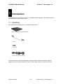
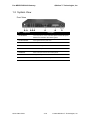
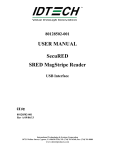
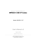
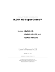
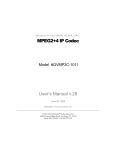
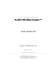
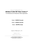
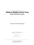
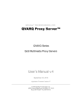
QVidium™ TECHNOLOGIES, INC. Pro-MPEG DVB-ASI Gateway Quick Start Guide © 2006 QVidium™ Technologies, Inc. 12989 Chaparral Ridge Road, San Diego, CA 92130 Phone 858.792.6407 • Fax 858.792.9131 Table of Contents 1 Introduction.............................................................................................................3 1.1 Unpacking.........................................................................................................3 1.2 System View.....................................................................................................4 Front View.................................................................................................................4 Rear View .................................................................................................................5 2 3 4 Configuring the System .......................................................................................6 2.1 Using the LCD Front Panel Console.............................................................6 2.2 Setting the Media Network IP Address .........................................................7 2.3 Ethernet Port Configuration............................................................................9 2.4 Setting the Netmasks and Gateway Address.............................................10 Transmitting a Stream........................................................................................11 3.1 Creating a network transmit stream............................................................11 3.2 Starting a network transmit stream .............................................................12 3.3 Stopping a network transmit stream ...........................................................12 Receiving a Stream .............................................................................................13 4.1 Creating a network receive stream .............................................................13 4.2 Starting a network receive stream...............................................................14 4.3 Stopping a network receive stream.............................................................14 5 Troubleshooting ..................................................................................................15 6 Appendix ...............................................................................................................16 6.1 Front Panel Console – Control/Configuration Menu.................................16 6.2 Front Panel Status Screens .........................................................................17 6.3 Electromagnetic Emissions and Safety Certifications ..............................18 Pro-MPEG DVB-ASI Gateway 1 QVidium™ Technologies, Inc. Introduction Congratulations on purchasing the QVidium™ Pro-MPEG DVB-ASI gateway. This chapter introduces the features and functions of the product. 1.1 Unpacking After unpacking the shipping carton, you should find these items: QVidium™ Pro-MPEG FEC DVB-ASI Gateway 1 rail kit 4 rubber feet 2 power cords (USA and Germany) Inspect all the items. If any item is damaged or missing, notify your dealer immediately. Keep the shipping carton and packing materials in case you need to ship or store the system in the future. Quick Start Guide 3/18 © 2006 QVidium™ Technologies, Inc. Pro-MPEG DVB-ASI Gateway QVidium™ Technologies, Inc. 1.2 System View Front View Ref Component 1 Power Button Description Turns the power on and off. You must press and hold the power button for 4 seconds to turn off the system. 2 Power Indicator Glows green when the power is on. 3 LAN1 Indicator Indicates a media network connection 4 LAN2 Indicator Indicates a management network connection 5 Flash Disk Indicator Indicates activity on the flash disk drive. 6 USB Ports Either of the ports connects to a USB keyboard. 7 LCD Screen Displays messages and values entered. 8 Control Buttons Allow you to enter network configuration information. Quick Start Guide 4/18 © 2006 QVidium™ Technologies, Inc. Pro-MPEG DVB-ASI Gateway QVidium™ Technologies, Inc. Rear View Ref Component 1 Ventilation Openings Description Maintain proper operating temperature. Do not cover or block the openings. 2 Power Connector Connects the power cord. 3 Power Switch Turns the main power of the system on and off. 4 LAN1 Connector Connects the LAN cable for media. 5 LAN2 Connector Connects the LAN cable for management. 6 Serial Port Connects a serial device. 7 VGA Port Connects an external CRT monitor. 8 USB Ports Either of the ports connects to an USB keyboard. 9 DVB-ASI connectors Allows you to connect ASI devices. ASI Connector View Close-Up Ref Component Description 1 Ref Clock Reference for ASI transmit 2 ASI Tx ASI transmit of network receive stream. 3 ASI Loop-through ASI transmit of ASI receive stream. 4 ASI Rx ASI receive to network transmit. Quick Start Guide 5/18 © 2006 QVidium™ Technologies, Inc. Pro-MPEG DVB-ASI Gateway 2 QVidium™ Technologies, Inc. Configuring the System This chapter tells you how to use the LCD Front Panel Console interface and how to configure basic system settings. However, the Front Panel Console is also capable of extensive control and configuration of the system. For a detailed view of the Front Panel menu structure and status screens, please see the Appendix. 2.1 Using the LCD Front Panel Console After you have made the network and power connections, you can configure the network settings using the LCD Front Panel Console. Before you begin, make sure that you have the following information ready: IP address assigned to the system Subnet mask of your network Gateway/router address (necessary only if communicating with other networks) The LCD screen on the front of the system displays two lines of text. The first line shows the information required; the second line shows the data already entered. You can enter the data by using the arrow buttons to the right of the LCD screen. The LCD screen has two modes of operation: status mode and control/configuration mode. In status mode, it rotates through a sequence of status screens. In control/configuration mode, it provides front-panel access to configuration, setup, and operation of the system. The Left arrow button moves the cursor to the left. The Right arrow button moves the cursor to the right. The Up arrow button increases the digit located at the cursor position The Down arrow button decreases the digit located at the cursor position. The S (Select) button accepts the data entered or selects the option displayed. In status mode, it toggles between holding and rotating among the status screens. The C (Cancel) button cancels the data entered or the option displayed. In status mode, it changes the mode to control/configuration mode. Quick Start Guide 6/18 © 2006 QVidium™ Technologies, Inc. Pro-MPEG DVB-ASI Gateway QVidium™ Technologies, Inc. 2.2 Setting the Media Network IP Address The Media IP Address corresponds to the LAN1 (Eth0) network interface. Follow the procedure below to set this IP address. NOTE: Both Ethernet ports (media and management) on the QVidium™ Pro-MPEG DVB-ASI Gateway have identical functionality. Either Ethernet interface can be used for media, management, or both types of traffic. The designation here of Media or Management interface is therefore an arbitrary designation – you can reassign their use to best suit your needs. 1. Press the (Cancel) button. You should see >TransmitIP on the second line. 2. Press the (Down) arrow button until you should see >Setup 3. Press the (Select) button. You should see the >LAN1 IP Addr option on the second line. LAN1 is the Media interface, although both LAN1 and LAN2 can be used for video traffic as well as system control. 4. Press the (Select) button. You should see on the display: LAN1 IP Addr 192.168.000.031 5. Use the Left and Right arrows to move the cursor to the digit in the IP Address that you want to change. 6. Use the Up and Down arrow keys to change the digits. 7. Press the (Select) button to save the change or use the (Cancel) button to not change the address. The IP address change takes effect immediately upon pressing Select. 8. Press the (Cancel) button twice to get back to the top level. Now that you have the IP address configured, you can use the web interface for more extensive configuration, such as adding routes or a gateway address or turning on DHCP. Alternatively, you can use the serial port connected to a terminal (set to 19200 Baud, 8-N-1) to change the IP settings. Log in as user “root” (no password is initially set) and run “configip” at the commandline prompt to set any of the IP parameters via any standard RS-232 ASCII terminal interface. Quick Start Guide 7/18 © 2006 QVidium™ Technologies, Inc. Pro-MPEG DVB-ASI Gateway QVidium™ Technologies, Inc. Setting the Management Network IP Address The Management IP Address corresponds to the LAN2 (Eth1) network interface. The following procedure allows you to change the Management IP Address. 1. Press the (Cancel) button. This takes you into Control/Configuration mode. You should see the following: >TransmitIP on the second line. 2. Press the (Down) arrow button until you should see the >Setup option. 3. Press the (Select) button. You should see the >LAN1 IP Addr option on the second line. 4. Press the (Down) arrow button. You should see the >LAN2 IP Addr option on the second line. LAN2 is the designation for the management interface. 5. Press the (Select) button. You should see on the display: LAN2 IP Addr 192.168.001.031 6. Use the Left and Right arrows to move the cursor to the digit in the IP Address that you want to change. 7. Use the Up and Down arrow keys to change the digits. 8. Press the (Select) button to save the change or use the the address. 9. Press the Quick Start Guide (Cancel) button to not change (Cancel) button 2 times to get back to the top level. 8/18 © 2006 QVidium™ Technologies, Inc. Pro-MPEG DVB-ASI Gateway QVidium™ Technologies, Inc. 2.3 Ethernet Port Configuration The physical characteristics of each Ethernet port, such as full or half duplex, port speed, and auto-negotiation capabilities can be set through the LCD Front Panel interface (and not via the web interface). Use the following procedure to reconfigure these characteristics of the Ethernet ports. 1. Press the (Down) arrow button until you should see the >Setup option on the second line. 2. Press the (Select) button. You should see the >LAN1 IP Addr option on the second line. 3. Press the (Down) arrow button. You should see the >LAN2 IP Addr option on the second line. 4. Press the (Down) arrow button. You should see the >LAN1 Phy option on the second line. (To set the physical characteristics for LAN2, press the (Down) arrow button one additional time to LAN2 Phy.) 5. Press the (Right) or (Left) arrow buttons to select the desired setting. You select among the following configuration settings: AUTO 100FD 100HD 10FD 10HD Auto-negotiation: 1000/100/10 Mbps, Full/Half-Duplex Force port to Full-Duplex at 100 Mbps data rate Force port to Half-Duplex at 100 Mbps data rate Force port to Full-Duplex at 10 Mbps data rate Force port to Half-Duplex at 10 Mbps data rate 6. Press the (Select) button to save the change, or use the your changes and keep the previous setting. 7. Press the Quick Start Guide (Cancel) button to discard (Cancel) button 2 times to get back to the top level. 9/18 © 2006 QVidium™ Technologies, Inc. Pro-MPEG DVB-ASI Gateway QVidium™ Technologies, Inc. 2.4 Setting the Netmasks and Gateway Address The netmasks and gateway IP address can be set from a web browser. 1. Enter http://IPAddress where IPAddress is the IP address of the management interface or the media interface. 2. The default netmasks are 255.255.255.0. You may not need to change them. 3. The default gateway is an IP address of a router or gateway on the same network that the media interface is connected to. For example if your media IP address is 192.168.0.30, the gateway’s IP address may be 192.168.0.1. 4. Press the Commit button to make the changes. You can also change the media and management interface’s IP address. IMPORTANT: If you change the IP address of the interface that the web browser is using, you will need to connect again to the system with the new IP address. Quick Start Guide 10/18 © 2006 QVidium™ Technologies, Inc. Pro-MPEG DVB-ASI Gateway 3 QVidium™ Technologies, Inc. Transmitting a Stream This chapter tells you how to use the web interface to create, start and stop media streams that you transmit on the network. However, you can also use the FrontPanel to control an IP network transmit stream. The Front Panel creates and uses a profile called FrontPanel that can also be edited and controlled via the web interface as described in this chapter. 3.1 Creating a network transmit stream Enter http://IPAddress where IPAddress is the IP address of the management interface or the media interface. 1. Select the TX Stream menu on the left side of the web page. 2. Select the Streams menu option underneath the TX Stream menu. A Network Transmit Streams interface should display in the main area to the right of the menu system. 3. Click on the New Stream button. The main area should display a form similar to the follow: Stream Name Destination IP Address or Hostname Tx UDP Port 10000 TS packets per IP packet 7 FEC Burst Size 10 FEC Rows 10 USE Row FEC 4. Enter a multicast IP address or an unicast IP address of another Pro-MPEG FEC system on the network. 5. Enter the name of the stream. 6. Press the Save button create the stream or press the Streams menu option on the left to return to the streams main area. Quick Start Guide 11/18 © 2006 QVidium™ Technologies, Inc. Pro-MPEG DVB-ASI Gateway QVidium™ Technologies, Inc. 3.2 Starting a network transmit stream Enter http://IPAddress where IPAddress is the IP address of the management interface or the media interface. 1. Select the TX Stream menu on the left side of the web page. 2. Select the Streams menu option underneath the TX Stream menu. A Network Transmit Streams interface should display in the main area to the right of the menu system. 3. Select a stream from the list. 4. Select the Start button. You should see: Stream 'name' started. where name is the stream you selected in step 3. 3.3 Stopping a network transmit stream Enter http://IPAddress where IPAddress is the IP address of the management interface or the media interface. 1. If the TX Stream menu is not shown, select the TX Stream menu on the left side of the web page. 2. Select the Stop menu option underneath the TX Stream menu. You should see the following message at the top of the web page main area. Stopping network transmit stream... Network transmit stopped. ASI no longer receiving stream. Quick Start Guide 12/18 © 2006 QVidium™ Technologies, Inc. Pro-MPEG DVB-ASI Gateway 4 QVidium™ Technologies, Inc. Receiving a Stream This chapter tells you how to use the web interface to create, start and stop media streams that you receive over a network. As with transmit stream control, you can also control network reception via the Front Panel. Setting network receive parameters from the Front Panel creates a network receive stream profile called FrontPanel that can also be edited and controlled via the web interface as described in this chapter. 4.1 Creating a network receive stream Enter http://IPAddress where IPAddress is the IP address of the management interface or the media interface. 1. Select the RX Stream menu on the left side of the web page. 2. Select the Streams menu option underneath the RX Stream menu. A Network Receive Streams interface should display in the main area to the right of the menu system. 3. Click on the New Stream button. The main area should display a form similar to the follow: New Stream Stream Name Rx UDP Port 10000 Multicast Address Network Jitter 50 Bitrate Note: If the stream has no PCRs (such as IPDC DVB-H streams), set the bitrate, otherwise leave the bitrate blank. 4. If you want to receive a multicast stream, enter a multicast address, otherwise leave it blank. 5. Enter the name of the stream. 6. Press the Save button to create the stream or press the Streams menu option on the left to return to the streams main area. Quick Start Guide 13/18 © 2006 QVidium™ Technologies, Inc. Pro-MPEG DVB-ASI Gateway QVidium™ Technologies, Inc. 4.2 Starting a network receive stream Enter http://IPAddress where IPAddress is the IP address of the management interface or the media interface. 1. Select the RX Stream menu on the left side of the web page. 2. Select the Streams menu option underneath the RX Stream menu. A Network Receive Streams interface should display in the main area to the right of the menu system. 3. Select a stream from the list. 4. Select the Start button. You should see: Stream 'name' started. where name is the stream you selected in step 3. 4.3 Stopping a network receive stream Enter http://IPAddress where IPAddress is the IP address of the management interface or the media interface. 1. If the RX Stream menu is not shown, select the RX Stream menu on the left side of the web page. 2. Select the Stop menu option underneath the RX Stream menu. You should see the following message at the top of the web page main area. Stopping ASI transmit... ASI transmit stopped. Network no longer receiving stream. Quick Start Guide 14/18 © 2006 QVidium™ Technologies, Inc. Pro-MPEG DVB-ASI Gateway 5 QVidium™ Technologies, Inc. Troubleshooting For troubleshooting information, the latest software and to contact us, call or e-mail us at: Phone: (858) 792-6407 E-mail: [email protected] Quick Start Guide 15/18 © 2006 QVidium™ Technologies, Inc. Pro-MPEG DVB-ASI Gateway 6 QVidium™ Technologies, Inc. Appendix 6.1 Front Panel Console – Control/Configuration Menu TransmitIP > Tx Control > Enter to: Start | Stop Tx Config > Dest IP Addr Dest Port # TS Pkts/IP #FEC Columns #FEC Rows Row FEC Off | On Receive IP > Rx Control > Enter to: Start | Stop Rx Config > Rcv Port Rx McastIP Net Jitter ASI Bitrate System > Name Ping > Ping IP Addr Ping Count Enter to: Stop | Start Clear PW NO | Yes Console VGA | RS232 Reboot NO | Yes Poweroff NO | Yes Setup > LAN1 IP Addr LAN2 IP Addr LAN1 Phy Auto | 100FD | 100HD | 10FD | 10HD LAN2 Phy Auto | 100FD | 100HD | 10FD | 10HD Quick Start Guide 16/18 © 2006 QVidium™ Technologies, Inc. Pro-MPEG DVB-ASI Gateway QVidium™ Technologies, Inc. 6.2 Front Panel Status Screens During normal operation, the Front Panel rotates among various status screens as shown below. At any time, you can force the display to stop screen rotation and pause at a particular display. DVB-ASI Gateway Front Panel Status Screen Sequence Main screen: Ping progress: Ping results: QVidiumDVB Cli:XX Scr:XX 192.168.001.031 Pkt#DD RT=SSS ms min/avg/max ms GotXX/YY ZZZ%Los Network bitrates: FEC receive stats: DVB bitrates: NetTx:XXXXXXXXX NetRx:YYYYYYYYY System name: SystemName ABC Gateway 1 System name: SystemName ABC Gateway 1 FEC Rec:XXXXXXX FEC Los:YYYYYYY Version: ASIRx:XXXXXXXXX ASITx:YYYYYYYYY System name: Version VERSION-BUILDNUM LAN 1 IP Address: LAN1 Media 010.010.240.171 SystemName ABC Gateway 1 LAN 2 IP Address: LAN2 Mgmt 192.168.001.031 Time: QVidium MM/DD HH:MM:SS System name: SystemName ABC Gateway 1 You can also use the left and right arrow keys to manually move to a different screen. Under certain conditions, such as when a transmit or receive session is started or during a Ping test, the Front Panel status display pre-empt the normal rotation of status screens to show current network or ping status screens (shown above with dashed or dotted outlines), as appropriate. After a brief period, the status screen rotation will revert to the standard order as shown above, but with the optional network status and/or ping status screens now enabled as appropriate. Quick Start Guide 17/18 © 2006 QVidium™ Technologies, Inc. Pro-MPEG DVB-ASI Gateway QVidium™ Technologies, Inc. 6.3 Electromagnetic Emissions and Safety Certifications FCC – Notice for the USA Compliance Information Statement (Declaration of Conformity Procedure) DoC FCC Part 15: Thus device complies with part 15 of the FCC Rules. Operation is subject to the following conditions: 1. This device may not cause harmful interference, and 2. This device must accept any interference received including interference that may cause undesired operation. If this equipment does cause harmful interference or radio or television reception, which can be determined by turning the equipment off and on, the user is encouraged to try one or more of the following measures: • Reorient or relocate the receiving antenna. • Increase the separation between the equipment and the receiver. • Plug the equipment into an outlet on a circuit different from that of the receiver. • Consult the dealer or an experienced radio/television technician for help. Notice for Canada This apparatus complies with the Class B limits for radio interference as specified in the Canadian Department of Communications Radio Interference Regulations. CE – Notice for Europe (CE Mark) This product is in conformity with the Council Directive 89/336/EEC, 92/31/EEC (EMC). UL – Underwriter Laboratories Approval for the USA Quick Start Guide 18/18 © 2006 QVidium™ Technologies, Inc.