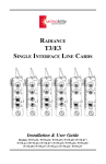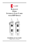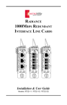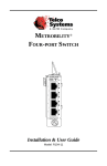
1
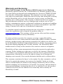
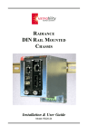
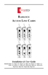
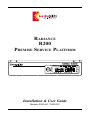
RADIANCE
R200
PREMISE SERVICE PLATFORM
MAN
FD PWR
LK
RX
DIS
LBK
LK
RX
DIS
LBK
Models: R200-AC / R200-DC
100 BASE
T
X
x
II
S
M
FX
Installation & User Guide
Radiance Series
R200:
R200-AC _____ Single slot platform with internal AC power supply
R200-DC _____ Single slot platform with internal DC power supply
Accessories:
R200-WM _____ Wall mounting bracket
The following is a listing of available Radiance products. Refer to each product’s
installation and user guide for operational features.
Platforms:
R400 Premise Service Platform
R1000 Premise Service Platform
R5000 Central Service Platform
Line Cards:
10Mbps
Copper to coax
Copper to fiber
Redundant
100Mbps
Copper to fiber
Fiber to fiber
Redundant
Access
10/100Mbps
Copper to copper
Copper to fiber
Fiber to fiber
Gigabit
Fiber to fiber
Copper to fiber
SONET
Fiber to fiber
T1/E1
Copper to fiber
T3/E3
Coax to Fiber
Management:
7501-M _______ Management card with single Ethernet interface
R502-M ______ Management card with dual Ethernet interfaces
NetBeacon™ ___ Management software
This publication is protected by the copyright laws of the United States and other countries, with all
rights reserved. No part of this publication may be reproduced, stored in a retrieval system, translated,
transcribed, or transmitted, in any form, or by any means manual, electric, electronic, electromagnetic,
mechanical, chemical, optical or otherwise, without prior explicit written permission of Metrobility Optical
Systems, Inc.
© 2002-03 Metrobility Optical Systems, Inc.
All rights reserved.
Printed in USA.
Table of Contents
Radiance R200 Premise Service Platform
Installation & User Guide
Overview .............................................................................................................. 4
Installation Guide ................................................................................................ 5
STEP 1: Unpack the Platform and Accessories ............................................. 5
STEP 2: Choose an Appropriate Location .................................................... 5
STEP 3: Install the Line Cards ...................................................................... 6
STEP 4: Connect to the Network .................................................................. 7
STEP 5: Attach the Grounding Lug (R200-DC Only) .................................. 7
STEP 6: Apply Power to the Platform ........................................................... 7
User Guide ........................................................................................................... 9
Platform Technical Specifications ................................................................. 9
Topology Solutions ....................................................................................... 9
Product Safety, EMC and Compliance Statements ..................................... 10
Warranty and Servicing ............................................................................... 11
Metrobility Optical Systems, the Metrobility Optical Systems logo, NetBeacon and WebBeacon are
trademarks of Metrobility Optical Systems, Inc. All others are trademarks of their respective owners.
The information contained in this document is assumed to be correct and current. The manufacturer is
not responsible for errors or omissions and reserves the right to change specifications at any time
without notice.
Overview
The Radiance R200 Premise Service Platoform is the ideal solution for the
installation of a single Radiance access line card at a remote site. While the
R200 supports all single-slot interface line cards, it provides an especially cost
effective way to manage a standalone access line card at the customer site. The
R200 features a solid metal housing and an internal AC or DC power supply.
With its compact design and optional wall mounting bracket, the R200 fits into
any type of office environment, even locations where shelving is unavailable.
Metrobility’s carrier class solutions provide seamless connectivity with all major
switch and router manufacturers and offer a flexible option for fiber connectivity
while reducing costs and adding functionality.
The R200 Premise Service Platform provides the following key features:
• Support for any single-slot, hot-swappable Radiance interface line card,
including the access line card.
• Internal AC or DC power supply.
• Optional wall mounting bracket.
• Strict standards compliance ensuring compatibility with other vendors’
equipment for flexible connectivity.
Related Documentation
Refer to the following documents for additional information:
• Radiance 10Mbps Single Interface Line Cards Installation & User Guide
• Radiance 100Mbps Single Interface Line Cards Installation & User Guide
• Radiance 10Mbps Redundant Interface Line Cards Installation & User
Guide
• Radiance 100Mbps Redundant Interface Line Cards Installation & User
Guide
• Radiance 10/100Mbps Interface Line Cards Installation & User Guide
• Radiance Gigabit Single Interface Line Cards Installation & User Guide
• Radiance SONET Single Interface Line Cards Installation & User Guide
• Radiance Access Line Cards Installation & User Guide
• Radiance T1/E1 Single Interface Line Cards Installation & User Guide
• Radiance T3/E3 Single Interface Line Cards Installation & User Guide
• Command Line Interface Reference Guide
• NetBeacon Element Management Software Installation & User Guide
• WebBeacon Management Software Installation & User Guide
4
Overview
Installation Guide
Follow the simple steps outlined in this section to install and start using the
Radiance R200 Premise Service Platform.
NOTE: Electrostatic discharge precautions should be taken when handling any
line card. Proper grounding is recommended (i.e., wear a wrist strap).
1
Unpack the Platform and Accessories
Check that the following components are included:
• Radiance R200 Premise Service Platform
• 1 power cord (R200-AC only)
• 4 rubber feet
• DC power plug connector (R200-DC only)
The following items are available separately:
• Radiance interface line cards
• Wall mounting bracket
Your order has been provided with the safest possible packaging, but
shipping damage does occasionally occur. Inspect it carefully. If you
discover any shipping damage, notify the carrier and follow their
instructions for damage and claims. Save the original shipping carton if
return or storage of the unit is necessary.
2
Choose an Appropriate Location
The Radiance R200 is intended for use in office and industrial environments. Attach the four rubber feet to the bottom of the unit and place it
on a flat surface. The feet provide a space for air circulation.
The R200 may be oriented in any manner that allows you to make the
physical connection to the power source and leaves a minimum of six
(6) inches of space around it for proper ventilation.
The R200-AC must be located within six (6) feet of the AC power
source being used and placed as far away as possible from electrical
noise generating equipment such as copiers, electrostatic printers and
other motorized equipment. If exposed twisted-pair wiring is used
nearby, the wiring should be routed as far away as possible from power
cords and data cables to minimize interference.
Radiance R200 Premise Service Platform
5
3
Install the Line Card
The R200 Premise Service Platform supports one single-slot Radiance
interface line card. A Radiance line card offers the ease of plug-andplay installation and is hot-swappable. Refer to the card’s documentation for detailed installation instructions.
Before installing any card, note the following:
• Remove the temporary slot protector by turning the thumb screw
counterclockwise and removing the blank panel.
• Set all switches and/or jumpers on the line card. Refer to the card’s
documentation for a complete description of its settings.
Follow the simple steps outlined below to install the line card:
• Grasp the card by the front panel as shown (thumb screw to the left).
• Line the edges of the board with the slot guides and slide the card in
until the edges are flush and even with the front of the unit. Do not
force the card into the slot. It should slide in easily and evenly.
• Secure to the R200 by turning the thumb screw clockwise until snug.
The line card is now ready for connection to the network.
Card Guide
x
II
MAN
FD PWR
LK
RX
DIS
LBK
RX
DIS
LK
LBK
Installation Guide
100 BASE
S
M
FX
6
4
5
Connect to the Network
6
Apply Power to the Platform
To connect to the network, refer to the card’s installation and user guide
for information about the cable types and lengths supported.
Attach the Grounding Lug (R200-DC Only)
On the back panel, the R200-DC has a small hole where a grounding
lug must be installed. The hole is marked with the grounding symbol.
Use a 6-32 screw to fasten the lug (not provided) to the platform.
Connect the other end of the grounding lug wire to the grounding point
at your site.
Power connections are located on the rear of the R200.
DC Power Supply Connections
IMPORTANT
• For installation in a restricted access location only.
• A readily accessible disconnect device must be incorporated in
the building installation wiring.
The R200-DC provides a three-position inverted header with screw
flanges (Phoenix Contact Combicon part number 1776511). For proper
connection to the power source, the header requires a plug connector
(Phoenix Contact Combicon part number 1777992 or equivalent).
NOTE: The plug connector is supplied with the R200. The input wire
leads are NOT supplied.
For DC connections, follow these guidelines:
IMPORTANT: Turn off the DC voltage source before beginning.
• Connect the wire leads from the voltage source to the appropriate
terminal on the plug connector and tighten the screws to secure the
wires in place.
Radiance R200 Premise Service Platform
7
DC plug connector
wire leads
• Insert the plug connector into the header on the R200 and tighten the
two screws.
+
48 VDC 1 AMP
DISCONNECT ALL POWER SOURCES BEFORE SERVICING
+
• Turn ON the DC voltage source.
• Verify proper power connection and operation by observing that the
power (PWR) LED on the line card is lit.
AC Power Supply Connections
For AC connections, follow these guidelines:
• Insert the power cord to the receptacle on the R200-AC.
• Connect the power cord plug to the AC power source.
• Verify proper power connection and operation by observing that the
power (PWR) LED on the line card is lit.
8
Installation Guide
User Guide
This section contains information regarding the technical specifications and
warranty for the Radiance R200 Premise Service Platform.
Platform Technical Specifications
Power
Input
R200-AC _________________________________ 100-250V AC, 50/60Hz
R200-DC _______________________________________ 48V DC (SELV)
Output ____________________________________________ 5V DC, 2A, 10W
Environmental
Operating Temperature ____________________________________ 0° to 50° C
Storage Temperature ____________________________________ -25° to 70° C
Relative Humidity __________________________ 5% to 95% non-condensing
Physical Case _________________________ Fully enclosed metal construction
Dimensions ____________________________________ 5.5"L x 7.5"W x 1.5"H
___________________________________ 14 cm x 19 cm x 3.8 cm
Weight _______________________________________________ 2.5 lb, 1.13 kg
Topology Solutions
Central Office/
POP
Customer Premises
SNMP Control
Radiance R5000
Sta
Rem
tus
ot
Rep
Usee Com
orti
figu
dB m
ng
and uni
rati
c
wid ati
on I
t
o
h=
nstr
0 ns P
Con
ucti
ons
ath
Radiance R200
Radiance R200 Premise Service Platform
9
Product Safety, EMC and Compliance Statements
This equipment complies with the following requirements:
• UL
• CSA
• CE
• EN60950 (safety)
• FCC Part 15, Class A
• EN55022-A (emissions)
• EN55024: 1998 (immunity)
• DOC Class A (emissions)
This product shall be handled, stored and disposed of in accordance with all
governing and applicable safety and environmental regulatory agency requirements.
The following FCC and Industry Canada compliance information is applicable
to North American customers only.
USA FCC Radio Frequency Interference Statement
This equipment has been tested and found to comply with the limits for a Class
A digital device, pursuant to Part 15 of the FCC Rules. These limits are designed
to provide reasonable protection against harmful interference when the equipment is operated in a commercial environment. This equipment generates, uses
and can radiate radio frequency energy, and if not installed and used in accordance with the instruction manual, may cause harmful interference to radio
communications. Operation of this equipment in a residential area is likely to
cause harmful interference in which case the user will be required to correct the
interference at his own expense.
Caution: Changes or modifications to this equipment not expressly approved by
the party responsible for compliance could void the user’s authority to operate
the equipment.
Canadian Radio Frequency Interference Statement
This Class A digital apparatus meets all requirements of the Canadian Interference-Causing Equipment Regulations.
Cet appareil numérique de la classe A respecte toutes les exigences du
Réglement sur le matériel brouilleur du Canada.
10
User Guide
Warranty and Servicing
Three-Year Warranty for the Radiance R200 Premise Service Platform
Metrobility Optical Systems, Inc. warrants that every Radiance product will be
free from defects in material and workmanship for a period of THREE YEARS
from the date of Metrobility shipment. This warranty covers the original user
only and is not transferable. Should the unit fail at any time during this warranty
period, Metrobility will, at its sole discretion, replace, repair, or refund the
purchase price of the product. This warranty is limited to defects in workmanship and materials and does not cover damage from accident, acts of God,
neglect, contamination, misuse or abnormal conditions of operation or handling,
including overvoltage failures caused by use outside of the product’s specified
rating, or normal wear and tear of mechanical components.
To establish original ownership and provide date of purchase, complete and
return the registration card or register the product online at
www.metrobility.com. This warranty will not go into effect until the warranty
registration has been received by Metrobility.
To return a defective product for warranty coverage, contact Metrobility
Customer Service for a return materials authorization (RMA) number. Send the
defective product postage and insurance prepaid to the address provided to you
by the Metrobility Technical Support Representative. Failure to properly protect
the product during shipping may void this warranty. The Metrobility RMA
number must be clearly on the outside of the carton to ensure its acceptance.
Metrobility will pay return transportation for product repaired or replaced inwarranty. Before making any repair not covered by the warranty, Metrobility
will estimate cost and obtain authorization, then invoice for repair and return
transportation. Metrobility reserves the right to charge for all testing and
shipping costs incurred, if test results determine that the unit is without defect.
This warranty constitutes the buyer’s sole remedy. No other warranties, such as
fitness for a particular purpose, are expressed or implied. Under no circumstances will Metrobility be liable for any damages incurred by the use of this
product including, but not limited to, lost profits, lost savings, and incidental or
consequential damages arising from the use of, or inability to use, this product.
Authorized resellers are not authorized to extend any other warranty on
Metrobility’s behalf.
Radiance R200 Premise Service Platform
11
Product Manuals
The most recent version of this manual is available online at
http://www.metrobility.com/support/manuals.htm
To obtain additional copies of this manual, contact your reseller, or call
1.877.526.2278 or 1.603.880.1833
Product Registration
To register your product, go to
http://www.metrobility.com/support/registration.asp
25 Manchester Street, Merrimack, NH 03054 USA
tel: 1.603.880.1833 • fax: 1.603.594.2887
www.metrobility.com
5660-000046 D
10/03