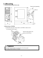
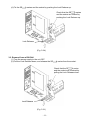
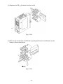
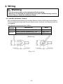
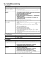
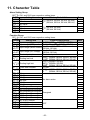
1
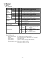
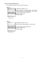
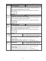
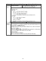
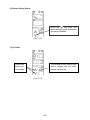
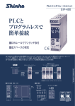
PLUG-IN TYPE
ALARM DETECTOR
SE
A SERIES
INSTRUCTION MANUAL
Preface
Thank you for purchasing the SE
A series Alarm Detector. This manual contains
instructions for the mounting, functions, operations and notes when operating the SE
A
series. To ensure safe and correct use, thoroughly read and understand this manual before
using this unit. To prevent accidents arising from the misuse of this instrument, please ensure
the operator receives this manual.
Notes
• This instrument should be used in accordance with the specifications described in the manual.
If it is not used according to the specifications, it may malfunction or cause a fire.
• Be sure to follow the warnings, cautions and notices. If they are not observed, serious injury
or malfunction may occur.
• Specifications of the SE
A series and the contents of this instruction manual are subject to
change without notice.
• Care has been taken to assure that the contents of this instruction manual are correct, but if
there are any doubts, mistakes or questions, please inform our sales department.
• This instrument is designed to be installed on a DIN rail within a control panel. If it is not, measures
must be taken to ensure that the operator does not touch power terminals or other high voltage
sections.
• Any unauthorized transfer or copying of this document, in part or in whole, is prohibited.
• Shinko Technos CO., LTD. is not liable for any damages or secondary damages incurred as a
result of using this product, including any indirect damages.
SAFETY PRECAUTIONS (Be sure to read these precautions before using our products.)
The safety precautions are classified into 2 categories: “Warning” and “Caution”.
Depending on the circumstances, procedures indicated by
Caution may cause serious
results, so be sure to follow the directions for usage.
Warning
Procedures which may lead to dangerous conditions and cause
death or serious injury, if not carried out properly.
Caution
Procedures which may lead to dangerous conditions and cause
superficial to medium injury or physical damage or may degrade or
damage the product, if not carried out properly.
Warning
• To prevent an electric shock or fire, only Shinko or other qualified service personnel may
handle the inner assembly.
• To prevent an electric shock, fire or damage to the instrument, parts replacement may only
be undertaken by Shinko or other qualified service personnel.
Safety Precautions
• To ensure safe and correct use, thoroughly read and understand this manual before using this
instrument.
• This instrument is intended to be used for industrial machinery, machine tools and measuring
equipment. Verify correct usage after purpose-of-use consultation with our agency or main office.
(Never use this instrument for medical purposes with which human lives are involved.)
• External protection devices such as protective equipment against excessive temperature rise, etc.
must be installed, as malfunction of this product could result in serious damage to the system or
injury to personnel. Also proper periodic maintenance is required.
• This instrument must be used under the conditions and environment described in this manual.
Shinko Technos Co., Ltd. does not accept liability for any injury, loss of life or damage occurring
due to the instrument being used under conditions not otherwise stated in this manual.
Caution with respect to Export Trade Control Ordinance
To avoid this instrument from being used as a component in, or as being utilized in the
manufacture of weapons of mass destruction (i.e. military applications, military equipment,
etc.), please investigate the end users and the final use of this instrument.
In the case of resale, ensure that this instrument is not illegally exported.
-2-
1. Installation Precautions
Caution
This instrument is intended to be used under the following environmental conditions
(IEC61010-1): Overvoltage category , Pollution degree 2
Ensure the mounting location corresponds to the following conditions:
• A minimum of dust, and an absence of corrosive gases
• No flammable, explosive gases
• No mechanical vibrations or shocks
• No exposure to direct sunlight, an ambient temperature of -5 to 55 (23 to 131 )
that does not change rapidly, and no icing
• An ambient non-condensing humidity of 35 to 85%RH
• No large capacity electromagnetic switches or cables through which large current is flowing
• No water, oil or chemicals or where the vapors of these substances can come into
direct contact with the unit
• If this instrument is installed within a control panel, the ambient temperature of the unit
- not the ambient temperature of the control panel - must be kept to under 55 (131 ).
Otherwise the life of electronic parts (especially electrolytic capacitors) of the unit will
be shortened.
Note: Avoid setting this instrument directly on or near flammable material even
though the case of this instrument is made of flame-resistant resin.
2. Wiring Precautions
Caution
• Do not leave wire remnants in the instrument, because they could cause a fire and/or a
malfunction.
• When wiring terminals, use a solderless terminal with an insulation sleeve in which an
M3 screw fits.
• Tighten the terminal screw using the specified torque.
If excessive force is applied to the screw when tightening, the screw may be damaged.
• This instrument has no built-in power switch, circuit breaker or fuse. It is necessary to
install them near the instrument.
(Recommended fuse: Time-lag fuse, rated voltage 250V AC, rated current 2A)
• For wiring of AC power source, be sure to use exclusive terminals as described in this
manual. If AC power source is connected to incorrect terminals, the unit will burn out.
• For a 24V DC power source, do not confuse polarity.
• Do not apply a commercial power source to the sensor connected to the input terminal nor
allow the power source to come into contact with the sensor, as the input circuit may burn out.
• Use a thermocouple, compensating lead wire and 3-wire type RTD according to the
sensor input specifications of this unit.
• When using DC voltage and current input, do not confuse polarity when wiring.
• Keep the input/output wires and power line separate.
3. Operation and Maintenance Precautions
Caution
• Do not touch live terminals. This may cause electric shock or problems in operation.
• Turn the power supply to the instrument OFF when retightening the terminal and
cleaning. Working on or touching the terminal with the power switched ON may result
in severe injury or death due to Electric Shock.
• Use a soft, dry cloth when cleaning the instrument.
(Alcohol based substances may tarnish or deface the unit.)
• As the display section is vulnerable, do not strike or scratch it with a hard object or
put pressure on it.
-3-
Model Explanation
Model names included in this manual are indicated below.
Name
SE
Model
SE2EA, SE2RA, SE2AA, SE2VA
SE1EA, SE1RA, SE1AA, SE1VA
SE2 A
SE1 A
A series
Characters Used in This Manual
Indication
Number, /
Indication
Alphabet
Indication
Alphabet
-1
0
1
2
3
4
5
6
7
8
9
A
B
C
D
E
F
G
H
I
J
K
L
M
N
O
P
Q
R
S
T
U
V
W
X
Y
Z
means that no character is indicated (unlit) on the display.
-4-
---
CONTENTS ---
1. Model
Page
1.1 Model ---------------------------------------------------------------------------- 6
1.2 How to Read the Model Label --------------------------------------------- 7
2. Name and Functions of Sections ------------------------------------------- 8
3. Mounting
3.1 External Dimensions (Scale: mm) ---------------------------------------- 9
3.2 Mounting to a DIN Rail ------------------------------------------------------ 9
3.3 Removal from a DIN Rail ------------------------------------------------- 11
4. Wiring
4.1 Lead Wire Solderless Terminal -----------------------------------------4.2 Terminal Arrangement and Circuit Configuration ------------------4.3 Wiring of Terminals
4.3.1 Power Source Wiring -------------------------------------------------4.3.2 Output Wiring ----------------------------------------------------------4.3.3 Input Wiring --------------------------------------------------------------
13
14
18
18
19
5. Key Operation Flowchart ---------------------------------------------------- 20
6. Setup
6.1 Indication after Power-on ------------------------------------------------6.2 Basic Operation of Setup ------------------------------------------------6.3 Setup
6.3.1 Function Group --------------------------------------------------------6.3.2 CH2 Function Group -------------------------------------------------6.3.3 Special Function Group ----------------------------------------------
27
28
30
40
40
7. Alarm Settings
7.1 Basic Operation of Alarm Settings ------------------------------------- 42
7.2 Alarm Settings
7.2.1 Alarm Setting Group -------------------------------------------------- 44
7.2.2 CH2 Alarm Setting Group ------------------------------------------- 45
8. Operation
8.1 Indication after Power-on ------------------------------------------------- 46
8.2 Unit Operation --------------------------------------------------------------- 48
9. Specifications ------------------------------------------------------------------- 51
10. Troubleshooting
10.1 Indication -------------------------------------------------------------------- 54
10.2 Key Operation -------------------------------------------------------------- 54
10.3 Operation -------------------------------------------------------------------- 54
11. Character Table ---------------------------------------------------------------- 55
-5-
1. Model
1.1 Model
SE
A Series
SE
2ch
alarm
detector
1ch
alarm
detector
Socket
2
2
2
2
1
1
1
1
AE
R
A
V
E
R
A
V
-
1
2
Power supply
0
1
0
Output points
1
2ch alarm detector (thermocouple)
2ch alarm detector (RTD)
2ch alarm detector (direct current) (*)
2ch alarm detector (DC voltage)
1ch alarm detector (thermocouple)
1ch alarm detector (RTD)
1ch alarm detector (direct current) (*)
1ch alarm detector (DC voltage)
Screw fall prevention, Finger-safe
(For Y terminal)
For Ring terminal
100 to 240 V AC
24 V AC/DC
SE2 A: 1 alarm output for each
2
channel
points
SE1 A: 2 alarm outputs
SE2 A: 3 alarm outputs for each
6
channel
points
SE1 A: 6 alarm outputs
(*) For direct current input, a shunt resistor (sold separately) is required.
(E.g.) SE2EA-1-0-0
Alarm detector type:
Socket:
Power supply:
Output points:
Factory default value:
2ch alarm detector (thermocouple)
Screw fall prevention, Finger-safe (For Y terminal)
100 to 240 V AC
2 points (1 alarm output for each channel)
CH1 input: K -200 to 1370
CH2 input: K -200 to 1370
-6-
1.2 How to Read the Model Label
The model label is attached to the left side of the case.
SE2 A
Model (E.g. SE2EA-1-0-0)
CH1 input (Enter a range selected in “Input range”.)
CH2 input (Enter a range selected in “Input range”.)
Power supply, Power consumption
Ambient temperature
Serial number
(Fig. 1.2-1)
SE1 A
Model (E.g. SE1EA-1-0-0)
Input (Enter a range selected in “Input range”.)
Power supply, Power consumption
Ambient temperature
Serial number
(Fig. 1.2-2)
-7-
2. Name and Functions of Sections
SE2 A
(1)
(2)
(3)
(4)
(5)
(6)
(8)
(7)
(9)
(10)
(Fig. 2-1)
SE1 A
(1)
(4)
(5)
(6)
(8)
(7)
(9)
(10)
(1) Power indicator (Green)
Lit when the power to the instrument is turned on.
(2) CH1 indicator (SE2 A) (Yellow)
Lit when CH1 is selected in [Display selection].
Flashes when CH1 alarm output is ON.
(3) CH2 indicator (SE2 A) (Yellow)
Lit when CH2 is selected in [Display selection].
Flashes when CH2 alarm output is ON.
(4) Input display (Red)
Indicates CH1 or CH2 input value selected in
[Display selection] in RUN mode.
Indicates setting item characters during
Setup and Alarm setting mode.
(5) Set value display (Red)
Indicates CH1 or CH2 A1 value or CH2 input
value selected in [Display selection] in RUN
mode.
Indicates the set value during Setup and Alarm
setting mode.
(6) UP Key ( )
Increases the numeric value, or switches the
selection items.
(7) DOWN Key ( )
Decreases the numeric value, or switches the
selection items.
(8) MODE Key ( )
Selects or switches a group, and registers the set
(or selected) value.
(9) SUB-MODE Key
Turns the displays ON again when they are in
OFF status.
(The UP, DOWN or MODE Key also turns the
displays ON again when they are in OFF
status.)
(10) Light sensor
Automatically measures and controls brightness of the Input and Set value displays.
(Fig. 2-2)
Notice
When setting the specifications and functions of this instrument, connect terminals 13 and
14 to a mains power cable first, then set them referring to “5. Key operation flowchart” and
“6. Setup” before performing “3. Mounting” and “4. Wiring”.
-8-
3. Mounting
3.1 External Dimensions (Scale: mm)
Socket (sold separately)
85
DIN rail
3
(Fig. 3.1-1)
(29)
79
30
108
3.2 Mounting to a DIN Rail
(1) Hook the upper part of the socket on the DIN rail, and mount it.
(A clicking sound is heard.)
Hook the upper part of the
socket on the DIN rail.
(Fig. 3.2-1)
Caution
Wire the instrument before inserting the unit into the socket.
For wiring, refer to Section “4. Wiring”.
-9-
3.3
(2) Confirm that the Lock Release is lowered.
Lock Release
(Fig. 3.2-2)
(3) Insert the SE
A series into the socket.
When inserting, be careful
about the position of pins
and slots.
(Fig. 3.2-3)
- 10 -
(4) Fix the SE
A series and the socket by pushing the Lock Release up.
Check that the SE
A series
and the socket are locked by
pushing the Lock Release up.
Lock Release
(Fig. 3.2-4)
3.3. Removal from a DIN Rail
(1) Turn the power supply to the unit OFF.
(2) Pull the Lock Release down, and release the SE
A series from the socket.
Check that the SE
A series
and the socket are unlocked by
pulling the Lock Release down.
Lock Release
(Fig. 3.3-1)
- 11 -
(3) Separate the SE
A series from the socket.
(Fig. 3.3-2)
(4) Remove the socket from the DIN rail by pulling the Socket Lock Release (at the
bottom of the socket) down.
(Fig. 3.3-3)
- 12 -
4. Wiring
Warning
Turn the power supply to the instrument off before wiring.
Working on or touching the terminal with the power switched on may result in
severe injury or death due to Electric Shock.
4.1 Lead Wire Solderless Terminal
Use a solderless terminal with an insulation sleeve in which an M3 screw fits as follows.
For the sockets with finger-safe & screw fall prevention functions, the Ring terminals are
incompatible.
The tightening torque should be 0.63N•m.
Solderless
Manufacturer
Model
Terminal
Y type
Nichifu Terminal Industries CO., LTD.
TMEV1.25Y-3S
Nichifu Terminal Industries CO., LTD.
TMEV 1.25-3
Ring type
Japan Solderless Terminal MFG CO., LTD. V1.25-3
(Scale: mm)
(Fig. 4.1-1)
- 13 -
4.2 Terminal Arrangement and Circuit Configuration
SE2EA
CH1
A3
output
CH2
A2
output
CH2
A3
output
TC
CH1
A2
output
+
CH1
-
Insulation
circuit
1
2
3
Display/Setting
key circuit
CH1
input
circuit
Insulation
circuit
4
+
CPU
5
CH2
-
6
TC
7
CH2
input
circuit
Insulation
circuit
Insulation
circuit
8
Power
circuit
CH1
output
circuit
CH2
output
circuit
13
+
14
-
9
10
11
Power supply
+
CH1 A1 output
+
CH2 A1 output
12
-
(Fig. 4.2-1)
SE2RA
RTD
CH1
A2
output
A
CH1
Insulation
circuit
1
B
2
B
3
CH1
A3
output
CH1
input
circuit
4
CPU
5
CH2 B
6
B
7
RTD
A
CH2
input
circuit
Insulation
circuit
CH2
A2
output
CH2
A3
output
Display/Setting
key circuit
Insulation
circuit
Insulation
circuit
8
(Fig. 4.2-2)
- 14 -
Power
circuit
CH1
output
circuit
CH2
output
circuit
13
+
Power supply
14
9
10
11
12
+
CH1 A1 output
+
CH2 A1 output
-
SE2AA
mA DC
CH1
A2
output
+
2
-
3
CH2
A2
output
Insulation
circuit
1
CH1
CH1
A3
output
CH2
A3
output
Display/Setting
key circuit
CH1
input
circuit
Insulation
circuit
4
CPU
+
5
Power
circuit
CH1
output
circuit
13
+
Power supply
14
9
+
CH1 A1 output
10
-
CH2
6
mA DC
7
CH2
input
circuit
Insulation
circuit
Insulation
circuit
8
CH2
output
circuit
11
+
CH2 A1 output
12
-
(Fig. 4.2-3)
CH1
A2
output
V DC
V( 1V) DC
SE2VA
+1
-
-2
3
CH1
Insulation
circuit
CH1
input
circuit
-6
7
V DC
CH2
V( 1V) DC
CH2
A3
output
Display/Setting
key circuit
Insulation
circuit
CPU
+5
+
CH2
A2
output
4
+
-
CH1
A3
output
CH2
input
circuit
Insulation
circuit
Insulation
circuit
8
Power
circuit
CH1
output
circuit
CH2
output
circuit
DC voltage input terminals:
V DC:
0 to 1 V DC
V(>1V) DC: 0 to 5 V DC, 1 to 5 V DC, 0 to 10 V DC
(Fig. 4.2-4)
- 15 -
13
14
9
10
11
+
Power supply
+
CH1 A1 output
+
CH2 A1 output
12
-
SE1EA
A4
output
A5
output
A6
output
TC
A3
output
+1
Insulation
circuit
CH1
- 2
Display/Setting
key circuit
Input
circuit
Power
circuit
13
+
Power supply
14
-
9
+
10
-
11
+
12
-
3
Insulation
circuit
4
CPU
5
6
Insulation
circuit
7
Output
circuit
Output
circuit
8
A1 output
A2 output
(Fig. 4.2-5)
SE1RA
A4
output
A5
output
A6
output
RTD
A3
output
A
Insulation
circuit
1
B
2
B
3
Input
circuit
4
CPU
Display/Setting
key circuit
Insulation
circuit
5
6
7
Insulation
circuit
8
(Fig. 4.2-6)
- 16 -
Power
circuit
Output
circuit
Output
circuit
13
+
Power supply
14
9
+
A1 output
10
11
+
A2 output
12
-
SE1AA
mA DC
A3
output
+
CH1
-
3
A5
output
Insulation
circuit
1
2
A4
output
Display/Setting
key circuit
Input
circuit
4
A6
output
Insulation
circuit
CPU
5
6
Insulation
circuit
7
Power
circuit
Output
circuit
Output
circuit
8
13
+
Power supply
14
-
9
+
A1 output
10
11
+
A2 output
12
-
(Fig. 4.2-7)
A3
output
+1
-
-
2
3
+
A4
output
A5
output
A6
output
V DC
V( 1V) DC
SE1VA
Insulation
circuit
Input
circuit
Display/Setting
key circuit
Insulation
circuit
4
CPU
5
6
Insulation
circuit
7
Power
circuit
Output
circuit
Output
circuit
8
DC voltage input terminals:
V DC:
0 to 1 V DC
V(>1V) DC: 0 to 5 V DC, 1 to 5 V DC, 0 to 10 V DC
(Fig. 4.2-8)
- 17 -
13
14
9
10
11
+
Power supply
+
A1 output
+
A2 output
12
-
4.3 Wiring of Terminals
Warning
• For 100 to 240V AC, if AC power source is connected to incorrect terminals,
this instrument will burn out.
• For a 24V DC power source, do not confuse polarity when wiring.
4.3.1 Power Source Wiring
Use terminals 13 (+) and 14 (-) for the power supply to the instrument.
4.3.2 Output Wiring
SE2 A: Use terminals 9 (+) and 10 (-) for CH1 A1 output wiring.
Use terminals 11 (+) and 12 (-) for CH2 A1 output wiring.
SE1 A: Use terminals 9 (+) and 10 (-) for A1 output wiring.
Use terminals 11 (+) and 12 (-) for A2 output wiring.
Take the following measures for contact protection and noise reduction of A1
output relay.
AC Power
AC
9
Inductive load (coil)
10
Load
Varistor, CR circuit, etc.
(Fig. 4.3.2-1)
DC Power
DC
9
Inductive load (coil)
10
Load
Diode, varistor,
CR circuit, etc.
(Fig. 4.3.2-2)
For 6-points output specification, alarm output connectors are attached at the
top of the unit. Refer to the alarm output corresponding to the connector number.
(Table 4.3.2-1)
Connector
Alarm Output
Number
SE2 A
SE1 A
1
CH1 A2 output
A3 output
2
CH1 A3 output
A4 output
3
CH2 A2 output
A5 output
4
CH2 A3 output
A6 output
- 18 -
Output specifications are shown below.
Open collector Control capacity: 0.1 A 24 V DC
Alarm output wiring example
SE
Alarm unit
A Top
SE
Wire harness
A Interior
+
DC power
(Fig. 4.3.2-3)
4.3.3 Input Wiring
Connection terminals differ depending on the input specifications.
Refer to (Fig. 4.2-1) to (Fig. 4.2-8).
SE2AA:
For CH1, use terminals 1 (+), 2 (-) for input wiring and shunt resistor connection.
For CH2, use terminals 5 (+), 6 (-) for input wiring and shunt resistor connection.
(See Table 4.3.3-1.)
SE1AA:
Use terminals 1 (+), 2 (-) for input wiring and shunt resistor connection.
(See Table 4.3.3-1.)
(Table 4.3.3-1)
Input
4 to 20 mA DC
0 to 20 mA DC
0 to 16 mA DC
2 to 10 mA DC
0 to 10 mA DC
1 to 5 mA DC
0 to 1 mA DC
Model
(for Y terminal)
Shunt Resistor
Model
(for Ring terminal)
RES-S06-050
RES-S01-050
50
0.1%
RES-S06-100
RES-S01-100
100
0.1%
RES-S06-200
RES-S06-01K
RES-S01-200
RES-S01-01K
200
1k
0.1%
0.1%
- 19 -
Specification
5. Key Operation Flowchart
SE2 A
POWER ON
RUN Mode
CH1
CH2
Alarm Setting Group
Alarm Setting Group
A1 value
A1 value
Scaling low limit to
Scaling high limit
CH1
Function Group
Input range
Scaling low limit to
Scaling high limit
See (Table5-1).
Decimal point place
A2 value
A2 value
Scaling low limit to
Scaling high limit
: No decimal point
Scaling low limit to
Scaling high limit
: 1 digit after point
:2 digits after point
:3 digits after point
A3 value
A3 value
Scaling low limit to
Scaling high limit
Scaling low limit to
Scaling high limit
Input Type and Range
Item
Input Type and Range
Thermocouple [SE2EA]
K -200 to 1370
K -328 to 2498
K 0 to 400
K 32 to 752
(*)
(*)
J -200 to 1000
J -328 to 1832
R -50 to 1760
R -58 to 3200
S -50 to 1760
S -58 to 3200
B 0 to 1820
B 32 to 3308
E -200 to 800
E -328 to 1472
T -200 to 400
(*)
T -328 to 752
N -200 to 1300
N -328 to 2372
PL-
PL-
0 to 1390
Scaling low limit to
Input range high limit
Filter time constant
0.0 to 10.0 sec
Sensor correction
-100.0 to 100.0
(*)
( )
A1 type
See (Table 5-2).
32 to 2534
W5Re/W26Re 0 to 2315
W5Re/W26Re 32 to 4199
W3Re/W25Re 0 to 2315
W3Re/W25Re 32 to 4199
A2 type
See (Table 5-2).
RTD [SE2RA]
Pt100 -200 to 850
(*)
JPt100 -200 to 500
(*)
Direct current [SE2AA]
Pt100 -328 to 1562
(*)
JPt100 -328 to 932
(*)
DC voltage [SE2VA]
4 to 20 mA DC -1999 to 9999
0 to 1 V DC -1999 to 9999
0 to 20 mA DC -1999 to 9999
0 to 5 V DC -1999 to 9999
0 to 16 mA DC -1999 to 9999
1 to 5 V DC -1999 to 9999
2 to 10 mA DC -1999 to 9999
0 to 10 mA DC -1999 to 9999
1 to 5 mA DC -1999 to 9999
0 to 1 mA DC -1999 to 9999
A3 type
See (Table 5-2).
0 to 10 V DC -1999 to 9999
(*) “No decimal point” or “1 digit after
decimal point” can be selected in
[Decimal point place].
[About Setting Items]
(Table 5-2)
Item
Input range low limit to
Scaling high limit
Scaling high limit
(Table 5-1)
Item
Scaling low limit
Alarm Type
No alarm action
High limit alarm
Low limit alarm
High limit with standby
Low limit with standby
• Upper left: Shows setting characters on the Input display.
Lower left: Shows factory default value on the Set value display.
Right: Shows setting items and ranges.
• Setting items and ranges differ depending on the model.
For details, refer to pages 24 to 45.
[Key Operation]
・
,
: If the
or
key is pressed, the unit moves to the next setting mode.
・Revets to RUN mode by pressing
for 3 seconds in any setting mode.
- 20 -
CH2
Function Group
A1 Energized/De-energized
: Energized
: De-energized
Setting items: Same as
CH1 function group.
Special Function
Group
Set value lock
: Unlock
: Lock 1
: Lock 2
A2 Energized/De-energized
Input sampling period
: Energized
: De-energized
: 25 ms
: 125 ms
: 250 ms
A3 Energized/De-energized
: Energized
: De-energized
Auto-light function
: Disabled
: Enabled
A1 HOLD function
: OFF
: ON
Display selection
: CH1 input value/
A1 value
: CH2 input value/
A1 value
: CH1 input value/
A2 HOLD function
: OFF
: ON
A3 HOLD function
CH2 input value
: No indication
: OFF
: ON
Indication time
A1 hysteresis
0.1 to 100.0
00.00 to 60.00(Min.Sec)
( )
A2 hysteresis
0.1 to 100.0
( )
A3 hysteresis
0.1 to 100.0
( )
A1 delay time
0 to 9999 sec
A2 delay time
0 to 9999 sec
A3 delay time
0 to 9999 sec
- 21 -
SE1 A
POWER ON
RUN Mode
Alarm setting
group
Function Group
A1 value
A4 value
Scaling low limit to
Scaling high limit
Input range
Scaling low limit to
Scaling high limit
See (Table 5-3).
Decimal point place
A2 value
A5 value
Scaling low limit to
Scaling high limit
Scaling low limit to
Scaling high limit
A3 value
A6 value
Scaling low limit to
Scaling high limit
Scaling low limit to
Scaling high limit
Input Type and Range
Item
Input Type and Range
Thermocouple [SE1EA]
K -200 to 1370
K -328 to 2498
K 0 to 400
K 32 to 752
(*)
(*)
J -200 to 1000
J -328 to 1832
R -50 to 1760
R -58 to 3200
S -50 to 1760
S -58 to 3200
B 0 to 1820
B 32 to 3308
E -200 to 800
E -328 to 1472
T -200 to 400
Input range low limit
to Scaling high limit
(*)
T -328 to 752
N -200 to 1300
N -328 to 2372
PL-
PL-
0 to 1390
Scaling low limit
to Input range high limit
Filter time constant
0.0 to 10.0 sec
Sensor correction
-100.0 to 100.0
(*)
( )
A1 type
See (Table 5-4).
32 to 2534
W5Re/W26Re 0 to 2315
W5Re/W26Re 32 to 4199
W3Re/W25Re 0 to 2315
W3Re/W25Re 32 to 4199
A2 type
See (Table 5-4).
RTD [SE1RA]
Pt100 -200 to 850
(*)
JPt100 -200 to 500
(*)
Direct Current [SE1AA]
Pt100 -328 to 1562
(*)
JPt100 -328 to 932
(*)
DC Voltage [SE1VA]
4 to 20 mA DC -1999 to 9999
0 to 1 V DC -1999 to 9999
0 to 20 mA DC -1999 to 9999
0 to 5 V DC -1999 to 9999
0 to 16 mA DC -1999 to 9999
1 to 5 V DC -1999 to 9999
2 to 10 mA DC -1999 to 9999
0 to 10 mA DC -1999 to 9999
1 to 5 mA DC -1999 to 9999
0 to 1 mA DC -1999 to 9999
0 to 10 V DC -1999 to 9999
(*) “No decimal point” or “1 digit after
decimal point” can be selected in
[Decimal point place].
A3 type
See (Table 5-4).
A4 type
See (Table 5-4).
A5 type
See (Table 5-4).
[About Setting Items]
(Table 5-4)
Item
Scaling low limit
Scaling high limit
(Table 5-3)
Item
: No decimal point
: 1 digit after point
: 2 digits after point
: 3 digits after point
Alarm Type
• Upper left: Shows setting characters on the Input display.
Low limit alarm
Lower left: Shows factory default value on the Set value display.
Right: Shows setting items and ranges.
• Setting items and ranges differ depending on the model.
For details, refer to pages 24 to 45.
High limit with standby
[Key Operation]
No alarm action
High limit alarm
Low limit with standby
•
,
: If the
or
key is pressed, the unit moves to the next setting mode.
• Reverts to RUN mode by pressing
for 3 seconds in any setting mode.
- 22 -
Special Function
Group
A6 type
See (Table 5-4).
A5 HOLD function
: OFF
: ON
: Unlock
: Lock 1
: Lock 2
A1 Energized/De-energized
: Energized
: De-energized
A6 HOLD function
Input sampling period
: OFF
: ON
A2 Energized/De-energized
: Energized
: De-energized
Set value lock
A1 hysteresis
0.1 to 100.0
: 25 ms
: 125 ms
: 250 ms
( )
Auto-light function
A3 Energized/De-energized
: Energized
A2 hysteresis
0.1 to 100.0
( )
: Disabled
: Enabled
: De-energized
A3 hysteresis
A4 Energized/De-energized
0.1 to 100.0
( )
: Energized
: De-energized
A4 hysteresis
0.1 to 100.0
( )
A5 Energized/De-energized
: Energized
: De-energized
Display selection
:
Input value/A1 value
: Input value
: A1 value
: No indication
A5 hysteresis
0.1 to 100.0
( )
Indication time
00.00 to 60.00 (Min.Sec)
A6 Energized/De-energized
: Energized
A6 hysteresis
0.1 to 100.0
: De-energized
A1 delay time
A1 HOLD function
0 to 9999 sec
: OFF
: ON
A2 delay time
0 to 9999 sec
A2 HOLD function
: OFF
: ON
A3 delay time
A3 HOLD function
A4 delay time
: OFF
0 to 9999 sec
0 to 9999 sec
: ON
A5 delay time
A4 HOLD function
0 to 9999 sec
: OFF
: ON
A6 delay time
0 to 9999 sec
- 23 -
( )
6. Setup
Setup should occur before using this unit, to set (or select) an Input range, Scaling low limit
value, Scaling high limit value, Alarm type, etc. according to the users’ conditions.
Setup is conducted in the CH1 function group, CH2 function group (SE2 A) and Special
function group.
Refer to the default values in (Table 6-1) to (Table 6-3).
If the users’ specifications are the same as the default value of the instrument, or if setup
has already been completed, it is not necessary to set up the instrument. Proceed to
Section “7. Alarm settings”.
Function Group
(Table 6-1) SE2 A (CH1 and CH2 have respective setting items.)
Setting Item
Factory Default Value
K -200 to 1370
(SE2EA)
Pt100 -200 to 850
(SE2RA)
Input range
4 to 20 mA DC -1999 to 9999 (SE2AA)
1 to 5 V DC -1999 to 9999
(SE2VA)
Decimal point place
No decimal point
-200
(SE2EA, SE2RA)
Scaling low limit
-1999 (SE2AA, SE2VA)
1370 (SE2EA)
Scaling high limit
850
(SE2RA)
9999 (SE2AA, SE2VA)
Filter time constant
0.0 sec
0.0
(SE2EA, SE2RA)
Sensor correction
0
(SE2AA, SE2VA)
A1 type
No alarm action
A2 type
A3 type
A1 Energized/De-energized
A2 Energized/De-energized
Energized
A3 Energized/De-energized
A1 HOLD function
A2 HOLD function
A3 HOLD function
A1 hysteresis
A2 hysteresis
A3 hysteresis
A1 delay time
A2 delay time
A3 delay time
OFF
1.0
(SE2EA, SE2RA)
1.0% (SE2AA, SE2VA)
0 sec
- 24 -
(Table 6-2) SE1 A
Setting Item
Input range
Decimal point place
Scaling low limit
Scaling high limit
Filter time constant
Sensor correction
A1 type
A2 type
A3 type
A4 type
A5 type
A6 type
A1 Energized/De-energized
A2 Energized/De-energized
A3 Energized/De-energized
A4 Energized/De-energized
A5 Energized/De-energized
A6 Energized/De-energized
A1 HOLD function
A2 HOLD function
A3 HOLD function
A4 HOLD function
A5 HOLD function
A6 HOLD function
A1 hysteresis
A2 hysteresis
A3 hysteresis
A4 hysteresis
A5 hysteresis
A6 hysteresis
Factory Default Value
K -200 to 1370
(SE1EA)
Pt100 -200 to 850
(SE1RA)
4 to 20 mA DC -1999 to 9999 (SE1AA)
1 to 5 V DC -1999 to 9999
(SE1VA)
No decimal point
-200
(SE1EA, SE1RA)
-1999 (SE1AA, SE1VA)
1370 (SE1EA)
850
(SE1RA)
9999 (SE1AA, SE1VA)
0.0 sec
0.0
(SE1EA, SE1RA)
0
(SE1AA, SE1VA)
No alarm action
Energized
OFF
1.0
(SE1EA, SE1RA)
1.0% (SE1AA, SE1VA)
- 25 -
Setting Item
A1 delay time
A2 delay time
A3 delay time
A4 delay time
A5 delay time
A6 delay time
Factory Default Value
0 sec
Special function group (Common to CH1 and CH2)
(Table 6-3)
Setting Item
Factory Default Value
Set value lock
Unlock
Input sampling period
250 ms
Auto-light function
Disabled
CH1 input value/A1 value (SE2 A)
Display selection
Input value/A1 value
(SE1 A)
Indication time
00.00 (Continuous indication)
- 26 -
6.1 Indication after Power-on
After power-on, the unit moves to warm-up status for approx. 3 seconds as shown below
in (Fig. 6.1-1) and (Fig. 6.1-2).
SE2 A
Lights when
power-on.
Indicates CH1 input range.
For the SE2VA, indicates
default value is 1 to 5 V DC.
as the factory
Indicates CH2 input range.
For the SE2VA, indicates
default value is 1 to 5 V DC.
as the factory
Indicates the input range.
For the SE1VA, indicates
default value is 1 to 5 V DC.
as the factory
(Fig. 6.1-1)
SE1 A
Lights when
power-on.
(Fig. 6.1-2)
- 27 -
After that, the unit switches to RUN mode as shown below in (Fig. 6.1-3), (Fig. 6.1-4).
SE2 A
Lights when
power-on.
The relevant indicator
lights when the Input
and Set value displays
indicate CH1 or CH2.
For the factory default value,
indicates CH1 input value.
Input
value
Set
value
For the factory default value,
indicates CH1 A1 value.
default value.
(Fig. 6.1-3)
SE1 A
Lights when
power-on.
For the factory default value,
indicates the input value.
Input
value
Set
value
For the factory default value,
indicates A1 value.
(Fig. 6.1-4)
6.2 Basic Operation of Setup
Setup is conducted in each function group.
For the SE2 A, CH1 and CH2 should be set respectively.
(E.g.) To enter the CH1 function group for the SE2VA:
(1) Press the
key 3 times in the RUN mode. (Fig. 6.2-1)
(2) Press the
key while CH1 function group characters are indicated.
(Fig. 6.2-2)
(3) The unit moves to the “Input range” selection item in CH1 function group.
To set (or select) each item, use the
or
key, and register the value
with the
key. (Fig. 6.2-3)
If the
key is pressed at the last setting item of each group, the unit
reverts to the RUN mode.
- 28 -
(1) RUN Mode
Input
value
Set
value
Press the
key 3 times in the RUN
mode.
(Fig. 6.2-1)
(2) CH1 Function Group
Press the
key while CH1 function
group characters are indicated.
(Fig. 6.2-2)
(3) Input Range Selection
To proceed to each setting item or to
register the set (selected) value in
CH1 function group, use this key.
To set (or select)
each item, use
these keys.
(Fig. 6.2-3)
- 29 -
6.3 Setup
6.3.1 Function Group
For the SE2 A, this is the function group for CH1.
To enter the function group, follow the procedures below.
(1)
(2)
Display
IN
OUT
Press the
key in the RUN mode until the left characters appear.
Press the
key.
For the SE2EA and SE1EA, thermocouple input range appears.
For the SE2RA and SE1RA, RTD input range appears.
For the SE2AA and SE1AA, direct current input range appears.
For the SE2VA and SE1VA, DC voltage input range appears.
Name, Function, Setting Range
Factory Default Value
Input range (SE2EA, SE1EA)
K -200 to 1370
• For the SE2EA and SE1EA, selects a thermocouple input range.
• Selection item:
: K
-200 to 1370
: K (*)
0
to 400
: J
-200 to 1000
: R
-50 to 1760
: S
-50 to 1760
: B
0
to 1820
: E
-200 to 800
: T (*)
-200 to 400
: N
-200 to 1300
: PL0
to 1390
: W5Re/W26Re 0
to 2315
: W3Re/W25Re 0
to 2315
: K
-328 to 2498
: K (*)
32 to 752
: J
-328 to 1832
: R
-58 to 3200
: S
-58 to 3200
: B
32 to 3308
: E
-328 to 1472
: T (*)
-328 to 752
: N
-328 to 2372
: PL32 to 2534
: W5Re/W26Re 32 to 4199
: W3Re/W25Re 32 to 4199
- 30 -
Display
IN
OUT
IN
OUT
IN
OUT
IN
OUT
IN
OUT
Name, Function, Setting Range
Input range (SE2RA, SE1RA)
Factory Default Value
Pt100 -200 to 850
• For the SE2RA and SE1RA, selects a RTD input range.
• Selection item:
: Pt100 (*)
-200 to 850
: JPt100 (*)
-200 to 500
: Pt100 (*)
-328 to 1562
: JPt100 (*)
-328 to 932
Input range (SE2AA, SE1AA)
4 to 20 mA DC -1999 to 9999
• For the SE2AA and SE1AA, selects a direct current input range.
• Selection item:
: 4 to 20 mA DC
-1999 to 9999
: 0 to 20 mA DC
-1999 to 9999
: 0 to 16 mA DC
-1999 to 9999
: 2 to 10 mA DC
-1999 to 9999
: 0 to 10 mA DC
-1999 to 9999
: 1 to 5 mA DC
-1999 to 9999
: 0 to 1 mA DC
-1999 to 9999
Input range (SE2VA, SE1VA)
1 to 5 V DC -1999 to 9999
• For the SE2VA and SE1VA, selects a DC voltage input range.
• Selection item:
: 0 to 1 V DC
-1999 to 9999
: 0 to 5 V DC
-1999 to 9999
: 1 to 5 V DC
-1999 to 9999
: 0 to 10 V DC
-1999 to 9999
Decimal point place
No decimal point
• Selects the decimal point place.
Available for the SE2AA, SE2VA, SE1AA and SE1VA.
For the SE2EA, SE2RA, SE1EA and SE1RA with (*) range, “No decimal
point” and “1 digit after decimal point” can be selected.
• Selection item:
: No decimal point
: 1 digit after decimal point
: 2 digits after decimal point
: 3 digits after decimal point
Scaling low limit
-200
(SE2EA, SE2RA, SE1EA, SE1RA)
-1999 (SE2AA, SE2VA, SE1AA, SE1VA)
• Sets scaling low limit value.
• Setting range:
SE2EA, SE2RA, SE1EA and SE1RA:
Input range low limit to Scaling high limit value
SE2AA, SE2VA, SE1AA and SE1VA:
-1999 to Scaling high limit value
- 31 -
Display Name, Function, Setting Range
Factory Default Value
IN
Scaling high limit
1370 (SE2EA, SE1EA)
OUT
850
(SE2RA, SE1RA)
9999 (SE2AA, SE2VA, SE1AA, SE1VA)
• Sets scaling high limit value.
• Setting range:
SE2EA. SE2RA, SE1EA and SE1RA:
Scaling low limit to Input range high limit
SE2AA, SE2VA, SE1AA and SE1VA:
Scaling low limit to 9999
IN
Filter time constant
0.0 sec
OUT
• Sets filter time constant.
Input fluctuation due to noise can be reduced.
• Setting range: 0.0 to 10.0 sec
IN
Sensor correction
0.0
(SE2EA, SE2RA, SE1EA, SE1RA)
OUT
0
(SE2AA, SE2VA, SE1AA, SE1VA)
• Sets sensor correction value.
Input value = Current input value +(Sensor correction value)
• Setting range:
SE2EA, SE2RA, SE1EA and SE1RA: -100.0 to 100.0 ( )
SE2AA, SE2VA, SE1AA and SE1VA: -1000 to 1000
- 32 -
Display Name, Function, Setting Range
Factory Default Value
IN
A1 type
No alarm action
OUT
• Selects an A1 type.
Note: If an A1 type is changed, the A1 value defaults to 0 (0.0).
• Selection item:
: No alarm action
: High limit alarm
: Low limit alarm
: High limit alarm with standby
: Low limit alarm with standby
• Alarm action:
High limit alarm
Low limit alarm
A1 hysteresis
A1 hysteresis
ON
ON
OFF
OFF
▲
High limit alarm
with standby
Low limit alarm
with standby
A1 hysteresis
A1 hysteresis
ON
ON
OFF
▲
A1 value
A1 value
OFF
▲
▲
A1 value
A1 value
Standby functions.
- 33 -
Standby functions.
Display Name, Function, Setting Range
Factory Default Value
IN
A2 type
No alarm action
OUT
• Selects an A2 type.
Available for 6 points alarm output for the SE2 A.
Note: If an A2 type is changed, the A2 value defaults to 0 (0.0).
• Selection item:
: No alarm action
: High limit alarm
: Low limit alarm
: High limit alarm with standby
: Low limit alarm with standby
• Alarm action:
Refer to the A1 action. (p.33)
IN
A3 type
No alarm action
OUT
• Selects an A3 type.
Available for 6 points alarm output for the SE1 A and SE2 A.
Note: If an A3 type is changed, the A3 value defaults to 0 (0.0).
• Selection item:
: No alarm action
: High limit alarm
: Low limit alarm
: High limit alarm with standby
: Low limit alarm with standby
• Alarm action:
Refer to the A1 action. (p.33)
IN
A4 type
No alarm action
OUT
• Selects an A4 type.
Available for 6 points alarm output for the SE1 A.
Note: If an A4 type is changed, the A4 value defaults to 0 (0.0).
• Selection item:
: No alarm action
: High limit alarm
: Low limit alarm
: High limit alarm with standby
: Low limit alarm with standby
• Alarm action:
Refer to the A1 action. (p.33)
- 34 -
Display Name, Function, Setting Range
Factory Default Value
IN
A5 type
No alarm action
OUT
• Selects an A5 type.
Available for 6 points alarm output for the SE1 A.
Note: If an A5 type is changed, the A5 value defaults to 0 (0.0).
• Selection item:
: No alarm action
: High limit alarm
: Low limit alarm
: High limit alarm with standby
: Low limit alarm with standby
• Alarm action: Refer to the A1 action. (p.33)
IN
A6 type
No alarm action
OUT
• Selects an A6 type.
Available for 6 points alarm output for the SE1 A.
Note: If an A6 type is changed, the A6 value defaults to 0 (0.0).
• Selection item:
: No alarm action
: High limit alarm
: Low limit alarm
: High limit alarm with standby
: Low limit alarm with standby
• Alarm action: Refer to the A1 action. (p.33)
IN
A1 Energized/De-energized
Energized
OUT
• Selects A1 action Energized or De-energized.
Not available if
(No alarm action) is selected in [A1 type].
• Selection item:
: Energized
: De-energized
IN
A2 Energized/De-energized
Energized
OUT
• Selects A2 action Energized or De-energized.
Not available if
(No alarm action) is selected in [A2 type].
• Selection item:
: Energized
: De-energized
IN
A3 Energized/De-energized
Energized
OUT
• Selects A3 action Energized or De-energized.
Not available if
(No alarm action) is selected in [A3 type].
• Selection item:
: Energized
: De-energized
- 35 -
Display Name, Function, Setting Range
Factory Default Value
IN
A4 Energized/De-energized
Energized
OUT
• Selects A4 action Energized or De-energized.
Not available if
(No alarm action) is selected in [A4 type].
• Selection item:
: Energized
: De-energized
IN
A5 Energized/De-energized
Energized
OUT
• Selects A5 action Energized or De-energized.
Not available if
(No alarm action) is selected in [A5 type].
• Selection item:
: Energized
: De-energized
IN
A6 Energized/De-energized
Energized
OUT
• Selects A6 action Energized or De-energized.
Not available if
(No alarm action) is selected in [A6 type].
• Selection item:
: Energized
: De-energized
IN
A1 HOLD function
OFF
OUT
• Selects OFF or ON for A1 HOLD function.
If alarm HOLD is selected, once A1 activates, A1 output ON status
will be maintained until power is turned OFF.
Not available if
(No alarm action) is selected in [A1 type].
• Selection item:
: OFF
: ON
IN
A2 HOLD function
OFF
OUT
• Selects OFF or ON for A2 HOLD function.
If alarm HOLD is selected, once A2 activates, A2 output ON status
will be maintained until power is turned OFF.
Not available if
(No alarm action) is selected in [A2 type].
• Selection item:
: OFF
: ON
IN
A3 HOLD function
OFF
OUT
• Selects OFF or ON for A3 HOLD function.
If alarm HOLD is selected, once A3 activates, A3 output ON status
will be maintained until power is turned OFF.
Not available if
(No alarm action) is selected in [A3 type].
• Selection item:
: OFF
: ON
- 36 -
Display Name, Function, Setting Range
Factory Default Value
IN
A4 HOLD function
OFF
OUT
• Selects OFF or ON for A4 HOLD function.
If alarm HOLD is selected, once A4 activates, A4 output ON status
will be maintained until power is turned OFF.
Not available if
(No alarm action) is selected in [A4 type].
• Selection item:
: OFF
: ON
IN
A5 HOLD function
OFF
OUT
• Selects OFF or ON for A5 HOLD function.
If alarm HOLD is selected, once A5 activates, A5 output ON status
will be maintained until power is turned OFF.
Not available if
(No alarm action) is selected in [A5 type].
• Selection item:
: OFF
: ON
IN
A6 HOLD function
OFF
OUT
• Selects OFF or ON for A6 HOLD function.
If alarm HOLD is selected, once A6 activates, A6 output ON status
will be maintained until power is turned OFF.
Not available if
(No alarm action) is selected in [A6 type].
• Selection item:
: OFF
: ON
IN
A1 hysteresis
1.0
(SE2EA, SE2RA, SE1EA, SE1RA)
OUT
1.0% (SE2AA, SE2VA, SE1AA, SE1VA)
• Sets A1 action hysteresis
Not available if
(No alarm action) is selected in [A1 type].
• Setting range:
SE2EA, SE2RA, SE1EA and SE1RA: 0.1 to 100.0 ( )
SE2AA, SE2VA, SE1AA and SE1VA: 0.1 to 100.0% of input span
IN
A2 hysteresis
1.0
(SE2EA, SE2RA, SE1EA, SE1RA)
OUT
1.0% (SE2AA, SE2VA, SE1AA, SE1VA)
• Sets A2 action hysteresis
Not available if
(No alarm action) is selected in [A2 type].
• Setting range:
SE2EA, SE2RA, SE1EA and SE1RA: 0.1 to 100.0 ( )
SE2AA, SE2VA, SE1AA and SE1VA: 0.1 to 100.0% of input span
- 37 -
Display Name, Function, Setting Range
Factory Default Value
IN
A3 hysteresis
1.0
(SE2EA, SE2RA, SE1EA, SE1RA)
OUT
1.0% (SE2AA, SE2VA, SE1AA, SE1VA)
• Sets A3 action hysteresis
Not available if
(No alarm action) is selected in [A3 type].
• Setting range:
SE2EA, SE2RA, SE1EA and SE1RA: 0.1 to 100.0 ( )
SE2AA, SE2VA, SE1AA and SE1VA: 0.1 to 100.0% of input span
IN
A4 hysteresis
1.0
(SE1EA, SE1RA)
OUT
1.0% (SE1AA, SE1VA)
• Sets A4 action hysteresis
Not available if
(No alarm action) is selected in [A4 type].
• Setting range:
SE2EA, SE2RA, SE1EA and SE1RA: 0.1 to 100.0 ( )
SE2AA, SE2VA, SE1AA and SE1VA: 0.1 to 100.0% of input span
IN
A5 hysteresis
1.0
(SE1EA, SE1RA)
OUT
1.0% (SE1AA, SE1VA)
• Sets A5 action hysteresis
Not available if
(No alarm action) is selected in [A5 type].
• Setting range:
SE2EA, SE2RA, SE1EA and SE1RA: 0.1 to 100.0 ( )
SE2AA, SE2VA, SE1AA and SE1VA: 0.1 to 100.0% of input span
IN
A6 hysteresis
1.0
(SE1EA, SE1RA)
OUT
1.0% (SE1AA, SE1VA)
• Sets A6 action hysteresis
Not available if
(No alarm action) is selected in [A6 type].
• Setting range:
SE2EA, SE2RA, SE1EA and SE1RA: 0.1 to 100.0 ( )
SE2AA, SE2VA, SE1AA and SE1VA: 0.1 to 100.0% of input span
IN
A1 delay time
0 sec
OUT
• Sets A1 action delay time.
A1 output does not turn ON until the set delay time has elapsed after
the input enters the A1 output range.
Not available if
(No alarm action) is selected in [A1 type].
• Setting range: 0 to 9999 sec
- 38 -
Display Name, Function, Setting Range
Factory Default Value
IN
A2 delay time
0 sec
OUT
• Sets A2 action delay time.
A2 output does not turn ON until the set delay time has elapsed after
the input enters the A2 output range.
Not available if
(No alarm action) is selected in [A2 type].
• Setting range: 0 to 9999 sec
IN
A3 delay time
0 sec
OUT
• Sets A3 action delay time.
A3 output does not turn ON until the set delay time has elapsed after
the input enters the A3 output range.
Not available if
(No alarm action) is selected in [A3 type].
• Setting range: 0 to 9999 sec
IN
A4 delay time
0 sec
OUT
• Sets A4 action delay time.
A4 output does not turn ON until the set delay time has elapsed after
the input enters the A4 output range.
Not available if
(No alarm action) is selected in [A4 type].
• Setting range: 0 to 9999 sec
IN
A5 delay time
0 sec
OUT
• Sets A5 action delay time.
A5 output does not turn ON until the set delay time has elapsed after
the input enters the A5 output range.
Not available if
(No alarm action) is selected in [A5 type].
• Setting range: 0 to 9999 sec
IN
A6 delay time
0 sec
OUT
• Sets A6 action delay time.
A6 output does not turn ON until the set delay time has elapsed after
the input enters the A6 output range.
Not available if
(No alarm action) is selected in [A6 type].
• Setting range: 0 to 9999 sec
- 39 -
6.3.2 CH2 Function Group
Available only for the SE2 A.
To enter the CH2 Function Group, follow the procedures below.
(1)
(2)
In the RUN mode, press the
key until the left characters appear.
Press the
key.
For the SE2EA, thermocouple input range selection item appears.
For the SE2RA, RTD input range selection item appears.
For the SE2AA, direct current input range selection item appears.
For the SE2VA, DC voltage input range selection item appears.
Setting items are the same as those of Section “6.3.1 Function Group”. (Pages 30
to 39)
Set up the unit referring to the explanation of Section “6.3.1 Function Group”.
6.3.3 Special Function Group
For the SE2 A, setting items are common to CH1 and CH2.
To enter the Special function group, follow the procedures below.
(1)
(2)
Display
IN
OUT
IN
OUT
IN
OUT
In the RUN mode, press the
key until the left characters appear.
Press the
key. “Set value lock” appears.
Name, Function, Setting Range
Factory Default Value
Set value lock
Unlock
• Locks the set values to prevent setting errors.
• Selection item:
: Unlock
: Lock 1 (None of the set values can be changed.)
: Lock 2 (Only alarm setting groups can be changed.)
Input sampling period
250 ms
• Selects the input sampling period.
• Selection item:
: 25 ms
: 125 ms
: 250 ms
Auto-light function
Disabled
• Selects Auto-light function Enabled/Disabled.
• Selection item:
: Disabled
: Enabled
- 40 -
Display
IN
OUT
IN
OUT
Name, Function, Setting Range
Factory Default Value
Display selection
CH1 input value/A1 value (SE2 A)
Input value /A1 value (SE1 A)
• Selects items to be indicated on the displays.
• Selection item:
SE2 A:
: CH1 input value /A1 value
: CH2 input value /A1 value
: Input value (CH1/CH2)
: No indication (Only the Power indicator is lit.)
SE1 A:
: Input value /A1 value
: Input value
: A1 value
: No indication (Only the Power indicator is lit.)
Indication time
00.00 (Continuous indication)
• Sets the indication time of the displays after final key operation.
Not available if
[No indication (Only the Power indicator is lit.)]
is selected in [Display selection].
Displays will go off (Only the Power indicator is lit.) after the indication
time has elapsed.
When the
,
,
or SUB-MODE key is pressed, or when power
is turned ON again, the displays will light again.
• Setting Range:
00.00: Continuous indication
00.01 (1 second) to 60.00 (60 minutes) (Minutes.Seconds)
- 41 -
7. Alarm Settings
7.1 Basic Operation of Alarm Settings
Alarm settings are conducted in the Alarm setting groups.
For the SE2□A, CH1, CH2 should be set respectively.
To enter the Alarm setting group, press the
key in the RUN mode. (Fig. 7.1-1)
Press the
key while Alarm setting group characters are being indicated. (Fig. 7.1-2)
The unit will proceed to the “A1 value” in the Alarm setting group.
For alarm settings, use the
or
key, and register the value with the
key.
(Fig. 7.1-3)
If the
key is pressed at the last setting item, the unit will revert to the RUN mode.
(1) RUN Mode
Input
value
Set
value
Press the
(Fig. 7.1-1)
- 42 -
once in the RUN mode.
(2) Alarm Setting Group
Press the
key while the
Alarm setting group characters
are being indicated.
(Fig. 7.1-2)
(3) A1 Value
Please use
these keys
for settings.
To proceed to each setting item
and to register the set value,
please use this key.
(Fig. 7.1-3)
- 43 -
7.2 Alarm Settings
7.2.1 Alarm Setting Group
For the SE2 A, this is the alarm setting group for CH1.
To enter the Alarm setting group, follow the procedures below.
(1)
(2)
In the RUN mode, press the
key once.
Press the
key. “A1 value” appears.
Display Name, Function, Setting Range
Factory Default Value
IN
A1 value
0
(SE2EA, SE2RA, SE1EA, SE1RA)
OUT
0
(SE2AA, SE2VA, SE1AA, SE1VA)
• Sets the A1 value.
Not available if
(No alarm action) is selected in [A1 type].
• Setting range:
Scaling low limit to Scaling high limit
IN
A2 value
0
(SE2EA, SE2RA, SE1EA, SE1RA)
OUT
0
(SE2AA, SE2VA, SE1AA, SE1VA)
• Sets the A2 value.
Not available if
(No alarm action) is selected in [A2 type].
• Setting range:
Scaling low limit to Scaling high limit
IN
A3 value
0
(SE2EA, SE2RA, SE1EA, SE1RA)
OUT
0
(SE2AA, SE2VA, SE1AA, SE1VA)
• Sets the A3 value.
Not available if
(No alarm action) is selected in [A3 type].
• Setting range:
Scaling low limit to Scaling high limit
IN
A4 value
0
(SE1EA, SE1RA)
OUT
0
(SE1AA, SE1VA)
• Sets the A4 value.
Not available if
(No alarm action) is selected in [A4 type].
• Setting range:
Scaling low limit to Scaling high limit
IN
A5 value
0
(SE1EA, SE1RA)
OUT
0
(SE1AA, SE1VA)
• Sets the A5 value.
Not available if
(No alarm action) is selected in [A5 type].
• Setting range:
Scaling low limit to Scaling high limit
IN
A6 value
0
(SE1EA, SE1RA)
OUT
0
(SE1AA, SE1VA)
• Sets the A6 value.
Not available if
(No alarm action) is selected in [A6 type].
• Setting range:
Scaling low limit to Scaling high limit
- 44 -
7.2.2 CH2 Alarm Setting Group
Available only for the SE2 A.
To enter the CH2 alarm setting group, follow the procedures below.
(1)
(2)
In the RUN mode, press the
key twice.
Press the
key. “A1 value” appears.
Setting items are the same as those of Section “7.2.1 Alarm setting group”. (p.44)
Refer to Section “7.2.1 Alarm setting group” for alarm settings.
- 45 -
8. Operation
8.1 Indication after Power-on
After power-on, the unit moves to warm-up status for 3 seconds as shown below
in (Fig. 8.1-1) and (Fig. 8.1-2).
SE2 A
Indicates CH1 input range.
See (Table 8.1-1). (p.47)
For the SE2VA,
is indicated
as the factory default value is 1 to 5
V DC.
Lights after
power-on.
Indicates CH2 input range.
See (Table 8.1-1). (p.47)
For the SE2VA,
is indicated
as the factory default value is 1 to 5
V DC.
(Fig. 8.1-1)
SE1 A
Indicates the input range.
See (Table 8.1-1). (p.47)
For the SE1VA,
is indicated
as the factory default value is 1 to 5
V DC.
Lights after
power-on.
(Fig. 8.1-2)
- 46 -
(Table 8.1-1)
Input
K
K
J
R
S
B
E
T
N
PLW5Re/W26Re
W3Re/W25Re
Pt100
JPt100
4 to 20 mA DC
0 to 20 mA DC
0 to 16 mA DC
2 to 10 mA DC
0 to 10 mA DC
1 to 5 mA DC
0 to 1 mA DC
0 to 1 V DC
0 to 5 V DC
1 to 5 V DC
0 to 10 V DC
Input Display
: -200 to 1370
:0
to 400
: -200 to 1000
: -50 to 1760
: -50 to 1760
:0
to 1820
: -200 to 800
: -200 to 400
: -200 to 1300
:0
to 1390
:0
to 2315
:0
to 2315
: -200 to 850
: -200 to 500
: -1999 to 9999
: -1999 to 9999
: -1999 to 9999
: -1999 to 9999
: -1999 to 9999
: -1999 to 9999
: -1999 to 9999
: -1999 to 9999
: -1999 to 9999
: -1999 to 9999
: -1999 to 9999
- 47 -
: -328 to 2498
: 32 to 752
: -328 to 1832
: -58 to 3200
: -58 to 3200
: 32 to 3308
: -328 to 1472
: -328 to 752
: -328 to 2372
: 32 to 2534
: 32 to 4199
: 32 to 4199
: -328 to 1562
: -328 to 932
8.2 Unit Operation
The unit enters the RUN mode after 3-second warm-up indication as shown in
(Fig. 8.2-1) and (Fig. 8.2-2).
SE2 A
Lights after
power-on.
The relevant
indicator lights
when the Input
and Set value
displays indicate
CH1 or CH2.
Input
value
Indicates the CH1 input value
for the factory default value.
Set
value
Indicates CH1 A1 value for the
factory default value.
(Fig. 8.2-1)
SE1 A
Lights after
power-on.
Indicates the input value for the
factory default value.
Input
value
Set
value
Indicates A1 value for the
factory default value.
(Fig. 8.2-2)
• Alarm Value Indication
If A1 value is selected in [Display selection] (*), indication can be changed
by pressing the
key evey one second as shown below.
SE2 A: A1 value
A2 value
SE1 A: A1 value
A2 value
A3 value
A1 value
A6 value
A1 value
When power is turned ON, the A1 value is indicated.
(*) SE2 A: When
is selected.
SE1 A: When
(CH1 input value/A1 value) or
(Input value/A1 value) or
- 48 -
(CH2 input value/A1 value)
(A1 value) is selected.
• Indication when Alarm Output is ON
SE2 A:
When alarm output is ON, the relevant channel indicator with current alarm output
ON will flash, and the contents selected in [Display selection] and
are
alternately indicated on the Set value display.
If the
key is pressed while holding down the
key, the channel with current
alarm output ON and Alarm output number will be indicated.
When plural alarm outputs are ON, each alarm output can be displayed every time
the
key is pressed while the
is held down.
(E.g.) When CH1 A1 and CH2 A3 are ON.
Set Value Display
Set value
Press the
key while the
key is held down.
Press the
key again while the
key is held down.
Press the
key again while the
key is held down.
If none of the keys are pressed, the unit will revert to the alternate
display of the set value and
.
SE1 A:
When alarm output is ON, the contents selected in [Display selection] and
are alternately indicated on the Set value display.
If the
key is pressed while holding down the
key, the alarm output number
with current alarm output ON will be indicated.
If plural alarm outputs are ON, each alarm output can be displayed by pressing the
key while the
is held down.
(E.g.) When A1 and A3 are ON
Set Value Display
Set value
Press the
key while the
Press the
key is held down.
key again while the
key is held down.
Press the
key again while the
key key is held down.
If none of the keys are pressed, the unit will revert to the alternate
display of the set value and
.
- 49 -
• Indication when input value is -200.0 (-2000) or less
When the range has a decimal point: For the indication of -200.0 or less, the input value
and the minus (-) sign are indicated alternately.
When DC voltage or current input is selected, the indication of -2000 or less is the
same as the above.
(E.g.) Indication of -200.0
IN
IN
• Indication when input value is 10000 or more
When DC voltage or current input is selected: For the indication of 10000 or more, the
lower 4 digits of input value are flashing.
(E.g.) Indication of 10020
IN
Flashes.
• Underrange, Overrange and Sensor Burnout indication
Underrange : If input value becomes -10% of the input span or less, "
" flashes on
the Input display.
Overrange : If input value becomes 110% of the input span or more, "
" flashes
on the Input display.
• Indication time setting
If indication time is set, the displays will go off after the indication time has elapsed.
(Only the power indicator remains lit.)
If power is turned ON again, or if any of the keys
,
,
is pressed while displays are unlit, the displays will light again.
- 50 -
or the SUB-MODE Key
9. Specifications
Input Specifications
SE2EA, SE1EA
SE2RA, SE1RA
Input resistance: 1 M or more
External resistance: 100
or less, However, B: 40
or less
Burnout: Upscale
Input:
Thermocouple
Input Range
K
-200 to 1370
-328 to 2498
J
-200 to 1000
-328 to 1832
R
-50 to 1760
-58 to 3200
S
-50 to 1760
-58 to 3200
B
0
to 1820
32 to 3308
E
-200 to 800
-328 to 1472
T
-200 to 400
-328 to 752
N
-200 to 1300
-328 to 2372
PL0
to 1390
32 to 2534
W5Re/W26Re
0
to 2315
32 to 4199
W3Re/W25Re
0
to 2315
32 to 4199
The minimum input span is 50 (100 ).
Input detection current: Approx. 0.2 mA
Allowable lead wire resistance: 10
or less per wire
Burnout: Upscale
Input:
RTD
Input Range
Pt100
-200 to 850
-328 to 1562
JPt100
-200 to 500
-328 to 932
The minimum input span is 50 (100 ).
SE2AA, SE1AA
Input
Shunt resistor
4 to 20 mA DC
0 to 20 mA DC
50
0 to 16 mA DC
2 to 10 mA DC
100
0 to 10 mA DC
1 to 5 mA DC
200
0 to 1 mA DC
1k
Connect a shunt resistor (sold separately) between input
terminals.
SE2VA, SE1VA
Input
Input
Resistance
0 to 1 V DC
0 to 5 V DC
1 to 5 V DC
0 to 10 V DC
1M
- 51 -
Allowable Signal
Source Resistance
2 k or less
1k
or less
Output Specifications
Alarm action
SE2 A: Up to 3 points alarm output for each channel can be
selected.
SE1 A: Up to 6 points alarm output can be selected.
For each alarm output, one alarm type can be selected in [Alarm
type] from the following.
High limit alarm
Low limit alarm
A1 hysteresis
A1 hysteresis
ON
ON
OFF
▲
OFF
High limit alarm
with standby
Low limit alarm
with standby
A1 hysteresis
A1 hysteresis
ON
ON
OFF
▲
OFF
Standby functions.
ON/OFF action
Alarm hysteresis
Alarm delay time
Alarm
Energized/De-energized
Alarm HOLD function
A1, A2 outputs
(SE1 A)
Relay contact, 1a
Control capacity
Electrical life
A2, A3 outputs
(SE2 A),
Open collector
Control capacity
A3 to A6 outputs
(SE1 A)
- 52 -
▲
A1 value
A1 value
A1 output (SE2 A),
▲
A1 value
A1 value
Standby functions.
SE2EA, SE2RA, SE1EA & SE1RA:
0.1 to 100.0 ( )
SE2AA, SE2VA, SE1AA & SE1VA:
0.1 to 100.0% of input span
0 to 9999 sec
Energized/De-energized, Selectable
OFF/ON, Selectable
3 A 250 V AC (resistive load)
1 A 250 V AC (inductive load cos
=0.4)
100,000 cycles
0.1 A 24 V DC
Performance
Reference input
accuracy (at 23 )
SE2EA and SE1EA:
Within 0.1% of each input span
R, S inputs -50 to 200 (-58 to 392 ): Within 6 (12 )
B input, 0 to 300 (32 to 572 ): Accuracy is not guaranteed.
K, J, E, T, N inputs, Less than 0 (32 ): Within 0.4% of
input span
SE2RA and SE1RA: Within 0.1% of each input span
SE2AA, SE2VA, SE1AA and SE1VA: Within 0.1%
Cold junction temper- Within 1 at -5 to 55 (SE2EA, SE1EA)
ature compensation
accuracy
Indication accuracy
Within Reference input accuracy 1 digit
Input sampling period 25 ms, 125 ms, 250 ms (Selectable via the keypad)
Temperature
0.015%/ or less
coefficient
Insulation resistance Input - Output - Power 10 M or more, at 500 V DC
Dielectric strength
Input - Output - Power 2.0 kV AC for 1 minute
General Structure
Case
Panel
Setting
Display
Flame-resistant resin, Color: Light gray
Membrane sheet
Setting by the front keypad
Input display: 7-segment, Red LED display 4-digit
Character size: 10 x 4.6 mm (H x W)
Set value display: 7-segment, Red LED display 4-digit
Character size: 10 x 4.6 mm (H x W)
Power indicator: Green LED
CH1 indicator: Yellow LED (SE2 A)
CH2 indicator: Yellow LED (SE2 A)
Installation Specifications
Power supply
100 to 240 V AC 50/60 Hz, 24 V AC/DC 50/60 Hz
Allowable voltage
85 to 264 V AC, 20 to 28 V AC/DC
fluctuation
Power consumption Approx. 9 VA
Ambient temperature -5 to 55
Ambient humidity
35 to 85%RH (non-condensing)
Weight
Approx. 200g (socket included)
Mounting
DIN rail
External dimensions W30 x H88 x D108mm (socket included)
Attached Functions
Auto-light function
Power failure
countermeasure
Self-diagnosis
Cold junction
temperature
compensation
Automatically measures and controls brightness of the displays
to conserve power.
The setting data is backed up in the non-volatile IC memory.
The CPU is monitored by a watchdog timer, and if an abnormal
status is found on the CPU, the instrument is switched to
warm-up status, turning all outputs OFF.
Available only for the SE2EA and SE1EA.
This detects the temperature at the connecting terminal between
the thermocouple and the instrument, and always maintains it at
the same status as if the reference junction location temperature
was at 0 (32 ).
- 53 -
10. Troubleshooting
10.1 Indication
Problem
Presumed Cause and Solution
The Input display is
flashing "
" or
"
".
The input value does not
change.
• The sensor may be burnt out.
Change each sensor.
• Check whether the sensor is securely connected to the
input terminals of the instrument.
Ensure that the sensor terminals are securely connected to
the input terminals of the instrument.
• Check the input signal source.
• Check whether polarity of thermocouple or compensating
lead wire is correct.
Check whether codes (A, B, B) of the RTD match the
instrument terminals.
Ensure that they are wired properly.
• Check whether the sensor input and temperature unit
( / ) settings are correct.
Ensure that sensor type and temperature unit ( / ) are set
properly.
• Check whether the sensor correction value is suitable.
Set it to a suitable value.
• AC leaks into the sensor circuit.
Use an ungrounded type sensor.
• There may be equipment that interferes with or makes
noise near the unit.
Keep equipment that interferes with or makes noise away
from the unit.
The indication of the
Input display is irregular
or unstable.
10.2 Key Operation
Problem
Presumed Cause and Solution
Settings are not possible. • “Lock 1” or “Lock 2” is selected in [Set value lock].
Select “Unlock”.
10.3 Operation
Problem
Alarm output does not
turn ON.
Alarm output does not
turn OFF.
Presumed Cause and Solution
• Check whether alarm value and alarm delay time have
been set to suitable values.
• Check whether Alarm type and Alarm Energized/
De-energized have been selected correctly.
• Check whether alarm value and alarm hysteresis have
been set to suitable values.
• Check whether Alarm type and Alarm Energized/
De-energized have been selected correctly.
• Check whether Alarm HOLD function is working.
To turn the alarm output OFF while Alarm HOLD function is
working, turn the power to the unit OFF.
- 54 -
11. Character Table
Alarm Setting Group
SE2 A: CH1 and CH2 have respective setting items.
Display
Setting Item
Factory Default Value
A1 value
0 (SE2EA, SE2RA, SE1EA, SE1RA)
A2 value
0 (SE2AA, SE2VA, SE1AA, SE1VA)
A3 value
A4 value
0 (SE1EA, SE1RA)
A5 value
0 (SE1AA, SE1VA)
A6 value
Data
Function Group
SE2 A: CH1 and CH2 have respective setting items.
Display
Setting Item
Factory Default Value
Data
Input range(thermocouple) K -200 to 1370
(SE2EA, SE1EA)
Input range (RTD)
Pt100 -200 to 850 (SE2RA, SE1RA)
Input range (direct current) 4 to 20 mA DC -1999 to 9999
(SE2AA, SE1AA)
Input range (DC voltage) 1 to 5 V DC -1999 to 9999
(SE2VA, SE1VA)
Decimal point place
No decimal point
-200 (SE2EA, SE2RA, SE1EA, SE1RA)
Scaling low limit
-1999 (SE2AA, SE2VA, SE1AA, SE1VA)
1370 (SE2EA, SE1EA)
850
(SE2RA, SE1RA)
Scaling high limit
9999 (SE2AA, SE2VA, SE1AA, SE1VA)
Filter time constant
0.0 sec
0.0
(SE2EA, SE2RA, SE1EA, SE1RA)
Sensor correction
0
(SE2AA, SE2VA, SE1AA, SE1VA)
A1 type
A2 type
A3 type
No alarm action
A4 type
A5 type
A6 type
A1 Energized/De-energized
A2 Energized/De-energized
A3 Energized/De-energized
Energized
A4 Energized/De-energized
A5 Energized/De-energized
A6 Energized/De-energized
A1 HOLD function
A2 HOLD function
OFF
A3 HOLD function
A4 HOLD function
- 55 -
Display
Setting Item
A5 HOLD function
A6 HOLD function
A1 hysteresis
A2 hysteresis
A3 hysteresis
A4 hysteresis
A5 hysteresis
A6 hysteresis
A1 delay time
A2 delay time
A3 delay time
A4 delay time
A5 delay time
A6 delay time
Factory Default Value
Data
OFF
1.0
(SE2EA, SE2RA, SE1EA, SE1RA)
1.0% (SE2AA, SE2VA, SE1AA, SE1VA)
1.0
(SE1EA, SE1RA)
1.0% (SE1AA, SE1VA)
0 sec
Special Function Group
SE2 A: Setting items are common to CH1 and CH2.
Display
Setting Item
Factory Default Value
Set value lock
Unlock
Input sampling
250 ms
period
Auto-light function
Disabled
CH1 input value/A1 value (SE2 A)
Display selection
Input value/A1 value
(SE1 A)
Indication time
00.00 (Continuous indication)
Data
******* Inquiries *******
For any inquiries about this unit, please contact the vendor where you
purchased the unit or our agency after checking the following.
(e.g.)
• Model ........................………. SE2EA-1-0-0
• Serial number ….................... No. 124F05000
In addition to the above, please let us know the details of malfunction, or
discrepancy, and the operating conditions.
SHINKO TECHNOS CO., LTD.
OVERSEAS DIVISION
Head Office: 2-5-1, Senbahigashi, Minoo, Osaka, Japan
http://www.shinko-technos.co.jp
URL:
Tel : +81-72-727-6100
E-mail:
[email protected]
Fax: +81-72-727-7006
No.SE21E1 2012.04