1
EMPIRE
Comfort Systems
INSTALLATION INSTRUCTIONS
AND
OWNER’S MANUAL
The Direct Vent Zero Clearance Gas
Fireplace Heater
DIRECT VENT
GAS FIREPLACE HEATER
MODEL SERIES
DVP36PP32EN-3
DVP36PP32EP-3
DVP36SP32EN-3
DVP36SP32EP-3
GAS-FIRED
Installer:
Leave this manual with the appliance.
Consumer: Retain this manual for future reference.
WARNING: If the information in these instructions
DUH QRW IROORZHG H[DFWO\ D ¿UH RU H[SORVLRQ PD\
result causing property damage, personal injury
or loss of life.
² 'RQRWVWRUHRUXVHJDVROLQHRURWKHUÀDPPDEOH
vapors and liquids in the vicinity of this or any
other appliance.
UL FILE NO. MH30033
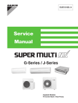
WARNING
HOT GLASS WILL
CAUSE BURNS.
DO NOT TOUCH GLASS
UNTIL COOLED.
NEVER ALLOW CHILDREN
TO TOUCH GLASS.
— WHAT TO DO IF YOU SMELL GAS
'RQRWWU\WROLJKWDQ\DSSOLDQFH
'RQRWWRXFKDQ\HOHFWULFDOVZLWFKGRQRWXVH
any phone in your building.
,PPHGLDWHO\ FDOO \RXU JDV VXSSOLHU IURP D
neighbor’s phone. Follow the gas supplier’s
instructions.
,I\RXFDQQRWUHDFK\RXUJDVVXSSOLHUFDOOWKH
¿UHGHSDUWPHQW
— Installation and service must be performed by a
TXDOL¿HGLQVWDOOHUVHUYLFHDJHQF\RUWKHJDVVXSplier.
WARNING: If not installed, operated and maintained
in accordance with the manufacturer’s instructions,
this product could expose you to substances in fuel
or from fuel combustion which can cause death or
serious illness.
This appliance may be installed in an aftermarket,
permanently located, manufactured home (USA only)
or mobile home, where not prohibited by state or local
codes.
This appliance is only for use with the type of gas
indicated on the rating plate. This appliance is not
FRQYHUWLEOHIRUXVHZLWKRWKHUJDVHVXQOHVVDFHUWL¿HG
kit is used.
Page 1
TABLE OF CONTENTS
Section
Page
Carton Contents ........................................................................................................................................... 3
Hardware Package ....................................................................................................................................... 3
Important Safety Information ........................................................................................................................ 4
Safety Information for Users of LP Gas........................................................................................................ 5
Requirements for Massachusetts ................................................................................................................. 6
Introduction................................................................................................................................................... 7
6SHFL¿FDWLRQV ............................................................................................................................................... 8
Fireplace Dimensions ................................................................................................................................... 9
Clearances ................................................................................................................................................. 10
Optional EMPT Series Mantel Installation - Peninsula Models Only .......................................................... 11
Locating Fireplace ...................................................................................................................................... 12
Gas Supply ................................................................................................................................................. 13
Rear Vent Conversion ................................................................................................................................ 14
Special Vent Systems................................................................................................................................. 14
Planning Installation ................................................................................................................................... 15
Fireplace Installation Instructions ..........................................................................................................15-16
Installation .............................................................................................................................................17-19
Venting Fireplace - Top .........................................................................................................................20-22
DVVK-4FV Direct Vent Termination Kit..................................................................................................23-29
Examples - Top Vent Run ........................................................................................................................... 30
Venting Fireplace - Rear ............................................................................................................................ 31
Examples - Rear Vent Run ......................................................................................................................... 32
Termination Clearances.............................................................................................................................. 33
Vent Clearances ......................................................................................................................................... 34
9HQW6\VWHP,GHQWL¿FDWLRQ .......................................................................................................................... 35
Framing and Finishing ...........................................................................................................................36-37
Horizontal Termination................................................................................................................................ 38
DVVK-4RE Vent Kit Installation Instructions..........................................................................................39-41
DVVK-4F Flex Vent Instructions ................................................................................................................. 42
Vertical Termination ...............................................................................................................................43-44
Placement of Glowing Embers ................................................................................................................... 45
Operation Instructions / Flame Appearance ............................................................................................... 46
Operating Instructions ...........................................................................................................................47-48
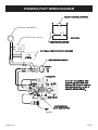
Standing Pilot Wiring Diagram.................................................................................................................... 49
Standing Pilot Lighting Instructions ............................................................................................................ 50
Standing Pilot Troubleshooting................................................................................................................... 51
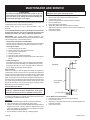
Maintenance and Service ........................................................................................................................... 52
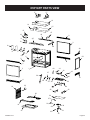
Parts List..................................................................................................................................................... 53
DVP36SP Parts View ................................................................................................................................. 54
DVP36PP Parts View ................................................................................................................................. 55
Wiring Instructions for Installing a Dual Switch / Receptacle...................................................................... 56
Accent Lamp............................................................................................................................................... 57
Optional FBB5 Blower Installation Instructions......................................................................................58-60
Accessories ................................................................................................................................................ 61
Master Parts Distributor List ....................................................................................................................... 62
How To Order Repair Parts ........................................................................................................................ 62
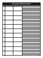
Appliance Service History........................................................................................................................... 63
Page 2
30786-0-0712
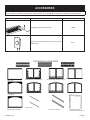
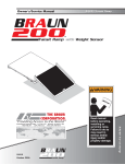
CARTON CONTENTS
Fireplace Assembly
Installation Package
3/8" x 12" Flexline
Rockwool Packet
Installation Instructions
Serial Number Tag
Recepticle, 3-Prong
Warranty Card
Cover, Junction Box
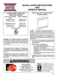
Hardware Package (See Figure Below)
Romex Connector (2)
#10 x 1/2" Phillips Hex Head Screw
#8-18 x 1/2" Phillips Truss Head
Screw
Nailing Flange
Additional Parts for Peninsula Models Only:
Canopy, End*
Canopy, Right*
Canopy, Left*
End Shield*
Canopy Corner Tie*
*Note: Installation required when using EMPT
series Peninsula Mantle
Canopy Hardware Package
Corner Tie - Canopy (2)
#10 x 1/2" Phillips Hex Head Screw (8)
#8-18 x 1/2" Phillips Truss Head Screw (4)
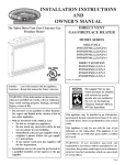
HARDWARE PACKAGE
ROMEX CONNECTOR (2)
CORNER TIE - CANOPY
(2 - PENINSULA MODELS)
NAILING FLANGE (8)
10 X ½ ” PHILLIPS HEX HEAD SCREW
#
(24 - PENINSULA MODELS)
(16 - SEE-THROUGH MODELS)
8-18 x½
#
” PHILLIPS TRUSS HEAD SCREW
(4 - PENINSULA MODELS)
Note: Hardware shown to scale where possible.
30786-0-0712
Page 3
IMPORTANT SAFETY INFORMATION
Before enclosing the vent pipe assembly, operate the appliance to ensure it is venting properly.
DO NOT OPERATE THIS APPLIANCE WITHOUT ALL GLASS DOOR PANELS INSTALLED
,IWKLVDSSOLDQFHLVLQVWDOOHGGLUHFWO\RQFDUSHWLQJ
tile or other combustible material other than wood
ÀRRULQJWKHDSSOLDQFHVKDOOEHLQVWDOOHGRQDPHWDO
or wood panel extending the full width and depth
of the appliance.
The base referred to above does not mean the
fireproof base as used on wood stoves. The
protection is for rugs that are extremely thick and
light colored tile.
&KLOGUHQDQGDGXOWVVKRXOGEHDOHUWHGWRWKHKD]DUGV
of high surface temperatures and should stay away
to avoid burns or clothing ignition.
<RXQJFKLOGUHQVKRXOGEHFDUHIXOO\VXSHUYLVHGZKHQ
they are in the same room as the appliance.
&ORWKLQJRURWKHUÀDPPDEOHPDWHULDOVKRXOGQRWEH
placed on or near the appliance.
'XHWRKLJKWHPSHUDWXUHVWKHDSSOLDQFHVKRXOGEH
ORFDWHGRXWRIWUDI¿FDQGDZD\IURPIXUQLWXUHDQG
draperies.
7KHJODVVIURQWRUDQ\SDUWUHPRYHGIRUVHUYLFLQJ
the appliance must be replaced prior to operating
WKHDSSOLDQFH:RUNVKRXOGEHGRQHE\DTXDOL¿HG
service person.
.HHSEXUQHUDQGFRQWUROFRPSDUWPHQWFOHDQ
9HQWFDSLVKRWZKLOH¿UHSODFHLVLQRSHUDWLRQ
Installation and repair should be done by a
QUALIFIED SERVICE PERSON. The appliance
should be inspected before use and at least annually
by a qualified service person. More frequent
cleaning may be required due to excessive lint from
carpeting, bedding materials, etc. It is imperative
that control compartments, burners and circulating
air passageways of the appliance be kept clean.
'2127SXWDQ\WKLQJDURXQGWKH¿UHSODFHWKDWZLOO
REVWUXFWWKHÀRZRIYHQWLODWLRQDLU
&OHDUDQFHLQDFFRUGDQFHZLWKORFDOLQVWDOODWLRQFRGHV
and the requirements of the gas supplier.
'2 keep the appliance area clear and free from
FRPEXVWLEOHPDWHULDOJDVROLQHDQGRWKHUÀDPPDEOH
Page 4
$GHTXDWHDFFHVVLELOLW\FOHDUDQFHVIRUVHUYLFLQJDQG
proper operation.
7KLV DSSOLDQFH PXVW QRW VKDUH RU EH FRQQHFWHG
WR D ÀXH VHUYLQJ D VHSDUDWH VROLGIXHO EXUQLQJ
appliance.
.HHS WKH DUHD DURXQG \RXU DSSOLDQFH FOHDU RI
FRPEXVWLEOHPDWHULDOVJDVROLQHDQGRWKHUÀDPPDEOH
vapor and liquids.
8QGHU QR FLUFXPVWDQFHV VKRXOG DQ\ VROLG IXHOV
(wood, coal, paper or cardboard etc.) be used in
this appliance.
7KHÀRZRIFRPEXVWLRQDQGYHQWLODWLRQDLUPXVWQRW
be obstructed in any way.
vapors and liquids.
'2 examine venting system periodically and replace
damaged parts.
'2make a periodic visual check of pilot and burners.
Clean and replace damaged parts.
&$87,21 7KH JODVV XVHG LQ \RXU ¿UHSODFH LV
tempered glass. If the glass is cracked or damaged in
any way, it should be replaced only with a complete
glass frame assembly from Empire. See parts list
on Pages 53 through 55 for ordering.
'2127XVHWKLV¿UHSODFHLIDQ\SDUWKDVEHHQXQGHU
ZDWHU,PPHGLDWHO\FDOODTXDOL¿HGVHUYLFHWHFKQLFLDQ
to inspect the heater and to replace any part of the
control system and any gas control which has been
under water.
$Q\VDIHW\VFUHHQRUJXDUGUHPRYHGIRUVHUYLFLQJ
an appliance must be replaced prior to operating
the appliance.
30786-0-0712
SAFETY INFORMATION FOR USERS OF LP GAS
3URSDQH/3*DVLVDÀDPPDEOHJDVZKLFKFDQFDXVH¿UHV
and explosions. In its natural state, propane is odorless and
colorless. You may not know all the following safety precautions which can protect both you and your family from an
accident. Read them carefully now, then review them point
by point with the members of your household. Someday
when there may not be a minute to lose, everyone’s safety
will depend on knowing exactly what to do. If, after reading the following information, you feel you still need more
information, please contact your gas supplier.
LP-GAS WARNING ODOR
If a gas leak happens, you should be able to smell the gas because of the odorant put in the LP-Gas.
That’s your signal to go into immediate action!
'RQRWRSHUDWHHOHFWULFVZLWFKHVOLJKWPDWFKHVXVH\RXUSKRQH
Do not do anything that could ignite the gas.
*HWHYHU\RQHRXWRIWKHEXLOGLQJYHKLFOHWUDLOHURUDUHD'R
that IMMEDIATELY.
&ORVHDOOJDVWDQNRUF\OLQGHUVXSSO\YDOYHV
/3*DVLVKHDYLHUWKDQDLUDQGPD\VHWWOHLQORZDUHDVVXFKDV
basements. When you have reason to suspect a gas leak, keep
RXWRIEDVHPHQWVDQGRWKHUORZDUHDV6WD\RXWXQWLO¿UH¿JKWHUV
declare them to be safe.
8VH\RXUQHLJKERU¶VSKRQHDQGFDOODWUDLQHG/3*DVVHUYLFH
SHUVRQ DQG WKH ¿UH GHSDUWPHQW (YHQ WKRXJK \RX PD\ QRW
continue to smell gas, do not turn on the gas again. Do not
re-enter the building, vehicle, trailer, or area.
FinallyOHWWKHVHUYLFHPDQDQG¿UH¿JKWHUVFKHFNIRUHVFDSHG
gas. Have them air out the area before you return. Properly
trained LP-Gas service people should repair the leak, then
check and relight the gas appliance for you.
NO ODOR DETECTED - ODOR FADE
Some people cannot smell well. Some people cannot smell the
RGRURIWKHFKHPLFDOSXWLQWRWKHJDV<RXPXVW¿QGRXWLI\RX
can smell the odorant in propane. Smoking can decrease your
ability to smell. Being around an odor for a time can affect your
sensitivity or ability to detect that odor. Sometimes other odors in
the area mask the gas odor. People may not smell the gas odor
or their minds are on something else. Thinking about smelling a
gas odor can make it easier to smell.
The odorant in LP-Gas is colorless, and it can fade under some
circumstances. For example, if there is an underground leak, the
PRYHPHQWRIWKHJDVWKURXJKVRLOFDQ¿OWHUWKHRGRUDQW2GRUDQWV
in LP-Gas also are subject to oxidation. This fading can occur if
there is rust inside the storage tank or in iron gas pipes.
The odorant in escaped gas can adsorb or absorb onto or into walls,
masonry and other materials and fabrics in a room. That will take
some of the odorant out of the gas, reducing its odor intensity.
LP-Gas may stratify in a closed area, and the odor intensity could
vary at different levels. Since it is heavier than air, there may be
more odor at lower levels. Always be sensitive to the slightest gas
odor. If you detect any odor, treat it as a serious leak. Immediately
go into action as instructed earlier.
SOME POINTS TO REMEMBER
/HDUQWRUHFRJQL]HWKHRGRURI/3*DV Your local LP-Gas
Dealer can give you a “Scratch and Sniff” pamphlet. Use it to
¿QGRXWZKDWWKHSURSDQHRGRUVPHOOVOLNH,I\RXVXVSHFWWKDW
your LP-Gas has a weak or abnormal odor, call your LP-Gas
Dealer.
,I\RXDUHQRWTXDOL¿HGGRQRWOLJKWSLORWOLJKWVSHUIRUPVHUYLFH
or make adjustments to appliances on the LP-Gas system. If
\RXDUHTXDOL¿HGFRQVFLRXVO\WKLQNDERXWWKHRGRURI/3*DV
prior to and while lighting pilot lights or performing service or
making adjustments.
6RPHWLPHV D EDVHPHQW RU D FORVHGXS KRXVH KDV D PXVW\
smell that can cover up the LP-Gas odor. Do not try to light
pilot lights, perform service, or make adjustments in an area
where the conditions are such that you may not detect the odor
if there has been a leak of LP-Gas.
2GRUIDGHGXHWRR[LGDWLRQE\UXVWRUDGVRUSWLRQRQZDOOVRI
new cylinders and tanks, is possible. Therefore, people should
be particularly alert and careful when new tanks or cylinders
are placed in service. Odor fade can occur in new tanks, or
UHLQVWDOOHGROGWDQNVLIWKH\DUH¿OOHGDQGDOORZHGWRVHWWRR
ORQJEHIRUHUH¿OOLQJ&\OLQGHUVDQGWDQNVZKLFKKDYHEHHQRXW
of service for a time may develop internal rust which will cause
odor fade. If such conditions are suspected to exist, a periodic
30786-0-0712
sniff test of the gas is advisable. If you have any question
about the gas odor, call your LP-Gas dealer. A periodic
sniff test of the LP-Gas is a good safety measure under
any condition.
,IDWDQ\WLPH\RXGRQRWVPHOOWKH/3*DVRGRUDQWDQG\RX
think you should, assume you have a leak. Then take the same
immediate action recommended above for the occasion when
you do detect the odorized LP-Gas.
,I\RXH[SHULHQFHDFRPSOHWH³JDVRXW´WKHFRQWDLQHULVXQGHU
no vapor pressure), turn the tank valve off immediately. If the
container valve is left on, the container may draw in some air
WKURXJKRSHQLQJVVXFKDVSLORWOLJKWRUL¿FHV,IWKLVRFFXUVVRPH
new internal rusting could occur. If the valve is left open, then
treat the container as a new tank. Always be sure your container is under vapor pressure by turning it off at the container
EHIRUHLWJRHVFRPSOHWHO\HPSW\RUKDYLQJLWUH¿OOHGEHIRUHLWLV
completely empty.
Page 5
REQUIREMENTS FOR MASSACHUSETTS
For all side wall horizontally vented gas fueled equipment installed
in every dwelling, building or structure used in whole or in part for
residential purposes, including those owned or operated by the
Commonwealth and where the side wall exhaust vent termination
LV OHVV WKDQ VHYHQ IHHW DERYH ¿QLVKHG JUDGH LQ WKH DUHD RI
the venting, including but not limited to decks and porches, the
IROORZLQJUHTXLUHPHQWVVKDOOEHVDWLV¿HG
1.
2.
INSTALLATION
OF
CARBON
MONOXIDE
DETECTORS.
At the time of installation of the side wall horizontal vented
JDVIXHOHGHTXLSPHQWWKHLQVWDOOLQJSOXPEHURUJDV¿WWHUVKDOO
observe that a hard wired carbon monoxide detector with an
DODUPDQGEDWWHU\EDFNXSLVLQVWDOOHGRQWKHÀRRUOHYHOZKHUH
the gas equipment is to be installed. In addition, the installing
SOXPEHU RU JDV¿WWHU VKDOO REVHUYH WKDW D EDWWHU\ RSHUDWHG
or hard wired carbon monoxide detector with an alarm is
installed on each additional level of the dwelling, building or
structure served by the side wall horizontal vented gas fueled
equipment. It shall be the responsibility of the property owner
WRVHFXUHWKHVHUYLFHVRITXDOL¿HGOLFHQVHGSURIHVVLRQDOVIRU
the installation of hard wired carbon monoxide detectors
a. In the event that the side wall horizontally vented gas
fueled equipment is installed in a crawl space or an attic,
the hard wired carbon monoxide detector with alarm and
battery back-up may be installed on the next adjacent
ÀRRUOHYHO
b. In the event that the requirements of this subdivision can
not be met at the time of completion of installation, the
owner shall have a period of thirty (30) days to comply with
the above requirements; provided, however, that during
said thirty (30) day period, a battery operated carbon
monoxide detector with an alarm shall be installed.
APPROVED CARBON MONOXIDE DETECTORS. Each
carbon monoxide detector as required in accordance with the
above provisions shall comply with NFPA 720 and be ANSI/
8/OLVWHGDQG,$6FHUWL¿HG
Page 6
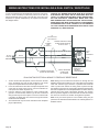
6,*1$*( $ PHWDO RU SODVWLF LGHQWL¿FDWLRQ SODWH VKDOO EH
permanently mounted to the exterior of the building at a
minimum height of eight (8) feet above grade directly in line
with the exhaust vent terminal for the horizontally vented
gas fueled heating appliance or equipment. The sign shall
read, in print size no less than one-half (1/2) inch in size,
“GAS VENT DIRECTLY BELOW. KEEP CLEAR OF ALL
OBSTRUCTIONS”.
4.
INSPECTION. The state or local gas inspector of the side
wall horizontally vented gas fueled equipment shall not
approve the installation unless, upon inspection, the inspector
observes carbon monoxide detectors and signage installed
in accordance with the provisions of 248 CMR 5.08(2)(a) 1
through 4.
(b) EXEMPTIONS: The following equipment is exempt from
248 CMR 5.08(2)(a)1 through 4:
1. The equipment listed in Chapter 10 entitled
“Equipment Not Required To Be Vented” in the most
current edition of NFPA 54 as adopted by the Board;
and
2. Product Approved side wall horizontally vented gas
fueled equipment installed in a room or structure
separate from the dwelling, building or structure
used in whole or in part for residential purposes.
(d) MANUFACTURER
REQUIREMENTS
GAS
EQUIPMENT VENTING SYSTEM NOT PROVIDED.
When the manufacturer of a Product Approved side
wall horizontally vented gas fueled equipment does not
SURYLGHWKHSDUWVIRUYHQWLQJWKHÀXHJDVHVEXWLGHQWL¿HV
“special venting systems”, the following requirements
VKDOOEHVDWLV¿HGE\WKHPDQXIDFWXUHU
1. The referenced “special venting system” instructions
shall be included with the appliance or equipment
installation instructions; and
2. The “special venting systems” shall be Product
Approved by the Board, and the instructions for
that system shall include a parts list and detailed
installation instruction.
(e) A copy of all installation instructions for all Product
Approved side wall horizontally vented gas fueled
equipment, all venting instructions, all parts lists for
venting instructions, and/or all venting design instructions
shall remain with the appliance or equipment at the
completion of the installation.
30786-0-0712
INTRODUCTION
Instructions to Installer
1. Installer must leave instruction manual with owner after
installation.
,QVWDOOHUPXVWKDYHRZQHU¿OORXWDQGPDLOZDUUDQW\FDUGVXSSOLHG
ZLWKWKH¿UHSODFH
3. Installer should show owner how to start and operate the
¿UHSODFH
7KLVGLUHFWYHQWJDV¿UHSODFHKHDWHULVGHVLJQHGWRRSHUDWHZLWK
all combustion air being siphoned from the outside of the building
and all exhaust gases expelled to the outside of the building. The
information contained in this manual pertains to all models and gas
control systems unless otherwise noted.
Warning: This unit is not for use with solid fuels.
$SSOLDQFH&HUWL¿FDWLRQ
7KLV ¿UHSODFH LV GHVLJQ FHUWL¿HG LQ DFFRUGDQFH ZLWK $PHULFDQ
National Standard/CSA Standard ANSI Z.21-88/CSA 2.33 and by
Underwriters Laboratories as a Direct Vent Gas Fireplace Heater
and shall be installed according to these instructions.
Consult your local building code agency, prior to installation, to ensure
compliance with local codes-including permits and inspections.
Warning: ANY CHANGE TO THIS FIREPLACE OR ITS
CONTROLS CAN BE DANGEROUS.
,PSURSHULQVWDOODWLRQRUXVHRIWKH¿UHSODFHFDQFDXVH
VHULRXVLQMXU\RUGHDWKIURP¿UHEXUQVH[SORVLRQV
or carbon monoxide poisoning.
Any alteration of the original design, installed other than as
shown in these instructions or use with a type of gas not
shown on the rating plate is the responsibility of the person
and company making the change.
Important
All correspondence should refer to complete Model Number, Serial
Number and type of gas.
High Altitude
When installing this unit at an elevation above 2000 feet (in the
United States) it may be necessary to decrease the input rating by
FKDQJLQJ WKH H[LVWLQJ EXUQHU RUL¿FH WR D VPDOOHU VL]H *HQHUDOO\
input should be reduced 4 percent for each 1000 feet above sea
level. However, if the heating value of the gas has been reduced,
this general rule may not apply. Check with local gas utility for proper
RUL¿FHVL]HLGHQWL¿FDWLRQ
7KH ¿UHSODFH ZKHQ LQVWDOOHG PXVW EH HOHFWULFDOO\ JURXQGHG LQ
accordance with local codes or, in absence of local codes, with the
National Electric Code ANSI/NFPA 70 or Canadian Electric code,
CSA C22.1, if an external electrical source is utilized.
Canadian High Altitude
Altitude: 0-4500 feet (0-1370 m)
These models may be installed in a bedroom or bed-sitting room
in the U.S.A. and Canada.
Consult your local gas utility for assistance in determining the proper
RUL¿FHIRUORFDWLRQ
4XDOL¿HG,QVWDOOLQJ$JHQF\
Installation and replacement of gas piping, gas utilization equipment
or accessories and repair and servicing of equipment shall be
SHUIRUPHGRQO\E\DTXDOL¿HGDJHQF\7KHWHUP³TXDOL¿HGDJHQF\´
PHDQVDQ\LQGLYLGXDO¿UPFRUSRUDWLRQRUFRPSDQ\ZKLFKHLWKHULQ
person or through a representative is engaged in and is responsible for
(a) the installation or replacement of gas piping or (b) the connection,
installation, repair or servicing of equipment, who is experienced in
such work, familiar with all precautions required and has complied
with all the requirements of the authority having jurisdiction.
Preparation
7KLVGLUHFWYHQWJDV¿UHSODFHDQGLWVFRPSRQHQWVDUHWHVWHGDQG
safe when installed in accordance with this Installation Manual.
5HSRUWWR\RXUGHDOHUDQ\SDUWVGDPDJHGLQVKLSPHQWVSHFL¿FDOO\
check glass condition. Do not install unit with damaged, incomplete,
or substitute parts. Read all instructions before starting installation
and follow these instructions carefully during installation to insure
PD[LPXPEHQH¿WDQGVDIHW\)DLOXUHWRIROORZWKHPZLOOYRLG\RXU
ZDUUDQW\DQGPD\SUHVHQWD¿UHKD]DUG
State of Massachusetts: The installation must be made by
DOLFHQVHGSOXPEHURUJDV¿WWHULQWKH&RPPRQZHDOWKRI
Massachusetts.
The installation must conform with local codes or, in the absence of
local codes, with the National Fuel Gas Code ANSI Z223.1/NFPA
54* Natural Gas and Propane Installation Code, or CSA B149.1 in
Canada. *Available from the American National Standards Institute,
Inc. 11 West 42nd St., New York, N.Y. 10036.
30786-0-0712
When installing this unit at an elevation above 4500 feet (in Canada),
check with local authorities.
The warranty will be voided by, and the warranter disclaims any
responsibility for the following actions:
,QVWDOODWLRQ RI DQ\ GDPDJHG ILUHSODFH RU YHQW V\VWHP
component.
0RGL¿FDWLRQRIWKH¿UHSODFHRUGLUHFWYHQWV\VWHP
,QVWDOODWLRQRWKHUWKDQDVLQVWUXFWHGE\(PSLUH&RPIRUW6\VWHPV
Inc.
,PSURSHUSRVLWLRQLQJRIWKHORJVJODVVGRRURUGHFRUDWLYHURFN
,QVWDOODWLRQDQGRUXVHRIDQ\FRPSRQHQWSDUWQRWPDQXIDFWXUHG
or approved by manufacturer.
Page 7
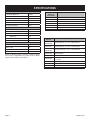
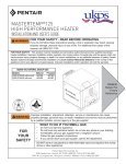
SPECIFICATIONS
DVP36(SP,PP) Nat Models
Input Btu/hr Maximum
Btu/hr Minimum (millivolt only)
KWH (Maximum)
(Minimum)
35,000
24,000
10.15
6.96
2UL¿FH
#33
Air Shutter Opening
5/16"
DVP36(SP,PP) LP Models
Input Btu/hr Maximum
Btu/hr Minimum (millivolt only)
KWH (Maximum)
(Minimum)
35,000
Remote Control
Options &
Accessories
FRBC
FRBTC
FRBTP
TRW
TMV
FWS-1
FREC
Millivolt Battery Remote ON/OFF
Millivolt Battery Remote T-Stat
Millivolt Battery Remote with Thermostat
Millivolt Wireless Wall Thermostat
Millivolt Reed Switch Wall Thermostat
Millivolt Wall Switch
Electric Remote
28,000
10.15
8.12
2UL¿FH
1.75 mm
Air Shutter Opening
FULL OPEN
DVP36(SP,PP) Nat and LP Models
Height without standoff
34 3/4" (883 mm)
Width, Face
39"
Depth
24"
Gas Inlet Shutoff Valve (pipe)
1/2" NPT
NOTE: Air shutter settings are factory minimum settings.
6RPHYHQWLQJFRQ¿JXUDWLRQVPD\UHTXLUHPLQRUDLUVKXWWHU
adjustments for optimum performance.
Venting
Options
DVVK-4TSP
(DVVK-4TS)
DVVK-4TP
(DVVK-4T)
DVVK-4RP
(DVVK-4R)
DVVK-4VP
(DVVK-4V)
DVVK-4F
DVVK-4RE
DV822
DVVK-4FV
DVEK-10
DVEK-25
Page 8
Description
Description
Top Vent Kit (Horz.) - 5" to 7" wall thickness
Top Vent Kit (Horz.) - 8" to 11" wall thickness
Rear Vent Kit (Horz.) - 5" to 7" wall thickness
Vertical Vent Kit
Horizontal Flex Vent Kit (4' Flex)
Horizontal Round Termination wall thickness 5" to 13 3/4"
Vinyl Siding Kit for DVVK-4RE
Vertical Flex Vent Kit (6' Flex / 4' Rigid = 10' Total)
10' Vent Extension Kit
25' Vent Extension Kit
30786-0-0712
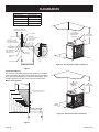
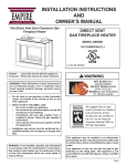
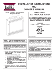
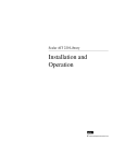
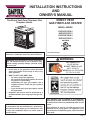
FIREPLACE DIMENSIONS
HORIZONTAL
VENT CONNECTION
7
7
C
C
SEE THRU
M
K
L
N
D
A H
M
F
32 ½
E
B
G
A H
J
J
K
L
PENINSULA
N
D
31 7/8
31
32 ½
E
B
I
I
17 ½
21
Figure 1
30786-0-0712
MODEL
DVP36SP32E
DVP36PP32E
A
34 3/4”
34 3/4”
B
39"
39"
C
24”
24”
D
22"
22"
E
36”
36”
F
29 1/4”
32 5/8”
G
22”
22”
H
41 1/8”
41 1/8”
I
1 1/4”
1 1/4”
J
5 3/8"
5 3/8"
K
2 1/2”
2 1/2”
L
6”
6”
M
25"
25"
N
33 1/2”
33 1/2”
MAX WEIGHT (LB)
240
230
Page 9
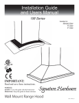
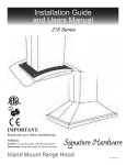
CLEARANCES
Clearance to Combustibles
Air Drop (End)
1/2" (12.7 mm)
Side
1/2" (12.7 mm)
Floor
0" (0 mm)
Top Stand-off
0" (0 mm)
Top Framing Edge
6 3/8" (161.7 mm)
SEE MANTLE CHART FOR
MAXIMUM MANTLE DEPTH
1 3/4” MIN.
PERPENDICULAR
COMBUSTIBLE
SIDEWALL
2” x 4” HEADER
STAND OFF
3” (76 mm) HEIGHT
ABOVE TOP OF
FIREPLACE
SEE MANTLE CHART
FOR MINIMUM HEIGHT
OF MANTLE ABOVE UNIT
42
”
MIN.
(CEILING TO
TOP OF DOOR)
FINISHED WALL
(COMBUSTIBLE)
6 3/8”
NON-COMBUSTIBLE
FIRST 6 3/8” (SEE
MAGNIFIED VIEW)
NAILING
FLANGES
TOP FRAMING
LEDGE
36
”
MIN.
GLASS FRONT
Figure 4a - See Through Fireplace Clearances
Figure 2
Combustible Material
'RQRWDWWDFKFRPEXVWLEOHPDWHULDOWRWKHPDQWHORI\RXU¿UHSODFH
7KLVLVD¿UHKD]DUG1RJUHHWLQJFDUGVVWRFNLQJVRURUQDPHQWDWLRQ
RIDQ\W\SHVKRXOGEHSODFHGRQRUDWWDFKHGWRWKH¿UHSODFH7KLVLV
DKHDWLQJDSSOLDQFH7KHÀRZRIKHDWFDQLJQLWHFRPEXVWLEOHV
Mantel Chart (Figure 3)
13
”M
/4
IN.
PERPEND
ICULAR
COM
USTIB
B
LE
SID
EW ALL
12” (305mm)
10” (254mm)
”
2
4
IM
N.
(CEILING TO
TOP OF DOOR)
MANTEL
COMBUSTIBLE TRIM AND MANTELS
ALLOWED IN SHADED AREA
8”
6”
4 1/2”
3 3/4”
18 3/8”
3”
2 1/4”
17 1/8”
1 1/2”
14 3/8”
12 3/8”
11 3/8”
8 3/8”
10 3/8”
9 3/8”
7 3/8”
3/4”
”
6
3
IM
N.
6 3/8”
TOP EDGE OF FIREPLACE
Figure 4b - Peninsula Fireplace Clearances
Figure 3
Page 10
30786-0-0712
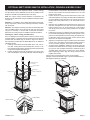
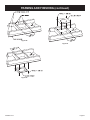
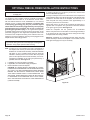
OPTIONAL EMPT SERIES MANTLE INSTALLATION - PENINSULA MODELS ONLY
7KH 3HQLQVXOD 'LUHFW 9HQW ¿UHSODFHV LQFOXGH D 3LHFH &DQRS\
and End Shield. These additional parts must be installed on the
¿UHSODFHLIWKH(037VHULHV0DQWHOWRSLVWREHXVHG
Note: The 3-piece canopy and End Shield is not required if the
¿UHSODFHLVWREH¿QLVKHGRIIXVLQJDQLQVWDOODWLRQPHWKRGDVVKRZQ
in Figure 4b.
Attention: For installation of the EMPT Mantel base and/or Mantel top components, reference the assembly instructions included
with the mantel.
Attention:7KH¿UHSODFHYHQWLQJPXVWVWDUWRIIKRUL]RQWDOO\ZKHQ
using the EMPT mantel. Once through the wall, the vent system
may be run vertically or continue with a horizontal termination.
Reference the venting section for additional mantel information.
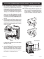
Installing the 3-Piece Canopy and End Shield
Prior to installing the Peninsula mantel, install the 3-piece canopy
and End Shield in conjunction with the (4) Mantel Corner Brackets
(included with the Mantel Top) as shown in Figure 5a. Refer to
the instructions included with the EMPT Mantel Top for additional
installation details.
1. Install (2) of the Mantel Corner Brackets at the vent end corQHUV ¿UVW /RRVHO\ DWWDFK HDFK EUDFNHW ZLWK RQH [ +H[+HDGVFUHZWKURXJKWKHUHDUÀDQJHDQGLQWRWKHSLORWKROH
RQWRSRIWKH¿UHSODFH6HH)LJXUH
2. Position the Rear Canopy with the mitered corner to the open
HQGRIWKH¿UHSODFH7KHFDQRS\ZLOOVOLGHXQGHUWKHÀDQJHRI
the Rear Mantel Corner Bracket. Align the holes in the canopy
with the corner bracket and loosely install a #10 x 1/2" Hex
Head screw to retain.
3. Position the Front Canopy with the mitered corner to the open
HQGRIWKH¿UHSODFH7KHFDQRS\ZLOOVOLGHXQGHUWKH5HDU0DQtel Corner Bracket. Align the holes in the Canopy and Corner
Bracket and loosely install a #10 x 1/2" Hex Head screw to
retain.
4. Place the other (2) Mantel Corner Brackets on top of the Front
DQG 5HDU &DQRSLHV QHDU WKH RSHQ HQG RI WKH ¿UHSODFH DQG
loosely install a #10 x 1/2" screw through the corner bracket
and canopy, then into the pilot holes provided. Do not tighten
the screws.
5. Install the End Canopy by sliding it under the Open End ManWHO &RUQHU %UDFNHW ÀDQJHV DQG DOLJQ PRXQWLQJ KROHV 7KHQ
place the End Shield above the End Canopy and Mantel Corner Brackets, align holes, then loosely secure all three parts
ZLWK[VFUHZVWRWKH¿UHSODFH
6. Adjust the canopies left to right as needed so that the mitered
corners meet, then tighten all previously installed screws to
secure end shield, canopies, and mantel corner brackets.
7R¿QLVKFDQRS\LQVWDOODWLRQLQVWDOOWZRFDQRS\FRUQHUWLH
brackets at the underside of the canopy corners as illustrated
by Figure 5a. Use a Phillips screwdriver to install two (2) #8 x
1/2 black sheet metal screws to attach each corner bracket.
Before tightening screws, align the canopy mitered corners
together then secure.
Figures 5 and 6 show placement of the corner brackets,
FDQRSLHVDQGWKHHQGVKLHOG)LJXUHVKRZVD¿QLVKHGYLHZRI
WKH¿UHSODFHPDQWHOWRSDQGEDVH
MANTEL SHELF
SUPPORT
REAR CANOPY
END SHIELD
CANOPY CORNER TIE
FRONT CANOPY
END CANOPY
Figure 6
30 1/8
”
(76
5 MM)
47 7/8
”
(12
16 MM)
Figure 5
END CANOPY
FRONT CANOPY
5 7/8
”
(149 MM)
CANOPY CORNER TIE
Figure 5a
30786-0-0712
Figure 7
Page 11
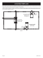
LOCATING FIREPLACE
Note:** Island (C) and Room Divider (D) installation is possible as long as the horizontal portion of the vent system (H) does not exceed
20 feet with a minimum vertical run of 8 feet. See details in Venting Section.
*When you install your Direct Vent Fireplace, a minimum of 1 3/4 inches clearance must be maintained from the perpendicular wall and
WKHIURQWRSHQLQJRIWKHDSSOLDQFH+RZHYHURQWKHYHQWHQGRIWKH¿UHSODFHLISODFHGDJDLQVWDZDOOWKHSHUSHQGLFXODUVLGHZDOOFOHDUDQFH
from the opening would be 2 1/2 inches.
(D) ROOM DIVIDER
INSTALLATION
(PENINSULA)
2 1/2
”
(REF.)
(H)
(C) ISLAND
INSTALLATION
(SEE-THRU)
2 1/2
”
(REF.)
(D) ROOM DIVIDER
INSTALLATION
(SEE-THRU)
Figure 8
Page 12
30786-0-0712
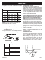
GAS SUPPLY
The gas pipeline can be brought in through the right or left side of
the appliance. Consult the current National Fuel Gas Code, ANSI
Z223.1 CAN/CGA-B149 (.1 or .2) installation code.
Each appliance should have its own manual gas cock.
A manual main gas cock should be located in the vicinity of the unit.
Where none exists, or where its size or location is not adequate,
contact your local authorized installer for installation or relocation.
Recommended Gas Pipe Diameter
Pipe Length
Installing a New Main Gas Cock
Schedule 40 Pipe
Inside Diameter
Tubing, Type L
Outside Diameter
Nat.
L.P.
Nat.
L.P.
0-10ft
0-3m
1/2"
12.7mm
3/8"
9.5mm
1/2"
12.7mm
3/8"
9.5mm
11-40ft
4-12m
1/2"
12.7mm
1/2"
5/8"
12.7mm 15.9mm
1/2"
12.7mm
41-100ft
13-30m
1/2"
12.7mm
1/2"
3/4"
12.7mm 19mm
1/2"
12.7mm
101-150ft
31-46m
3/4"
19mm
1/2"
7/8"
12.7mm 22.2mm
3/4"
1.9 mm
Compounds used on threaded joints of gas piping shall be resistant
WRWKHDFWLRQRIOLTXH¿HGSHWUROHXPJDVHV7KHJDVOLQHVPXVWEH
checked for leaks by the installer. This should be done with a soap
solution watching for bubbles on all exposed connections, and if
unexposed, a pressure test should be made.
1HYHUXVHDQH[SRVHGÀDPHWRFKHFNIRUOHDNV$SSOLDQFHPXVW
be disconnected from piping at inlet of control valve and pipe
capped or plugged for pressure test. Never pressure test with
DSSOLDQFHFRQQHFWHGFRQWUROYDOYHZLOOVXVWDLQGDPDJH
NOTE: The millivolt gas controls are equipped with a captured screw
type pressure test point, therefore it is not necessary to provide a
1/8" test point up stream of the control.
:KHQXVLQJFRSSHURUÀH[FRQQHFWRUXVHRQO\DSSURYHG¿WWLQJV
Note:1HYHUXVHSODVWLFSLSH&KHFNWRFRQ¿UPZKHWKHU\RXU
local codes allow copper tubing or galvanized.
Note: Since some municipalities have additional local codes, it is
always best to consult your local authority and installation code.
The use of the following gas connectors is recommended:
—
ANS Z21.24 Appliance Connectors of Corrugated Metal Tubing
and Fittings.
— ANS Z21.45 Assembled Flexible Appliance Connectors of Other
Than All-Metal Construction
The above connectors may be used if acceptable by the authority
KDYLQJMXULVGLFWLRQ7KHVWDWHRI0DVVDFKXVHWWVUHTXLUHVWKDWDÀH[LEOH
appliance connector cannot exceed three feet in length.
7KHDSSOLDQFHDQGLW¶VLQGLYLGXDOVKXWRIIYDOYHPXVWEHGLVFRQQHFWHG
from supply piping system during any pressure testing of that system
at test pressures in excess of 1/2 psig (3.5kPa).
The appliance must be isolated from the gas supply piping system
by closing its individual manual shut off valve during any pressure
testing of the gas supply piping system at test pressures equal to
or less than 1/2 psig (3.5kPa).
Attention! If one of the procedures results in pressures in excess of
SVLJZFN3DRQWKH¿UHSODFHJDVYDOYHLWZLOOUHVXOW
in a hazardous condition.
Checking Manifold Pressures
Both Propane and Natural gas valves have a built-in pressure
regulator in the gas valve. Natural gas models will have a manifold
pressure of approximately 3.5" w.c. (.871kPa) at the valve outlet
with the inlet pressure to the valve from a minimum of 4.5" w.c.
(1.120kPa) for the purpose of input adjustment to a maximum of
14.0" w.c. (3.484kPa). Propane gas models will have a manifold
pressure approximately 10.0" w.c. (2.49kPa) at the valve outlet
with the inlet pressure to the valve from a minimum of 10.8" w.c.
(2.68kPa) for the purpose of input adjustment to a maximum of
14.0" w.c. (3.484kPa).
Figure 9
Gas Supply Pressure (inches
w.c.)
Minimum
Normal
Maximum
Natural Gas
4.5"
7.0"
14.0"
LP (Propane)
10.8"
11.0"
14.0"
ELECTRICAL ACCESS
Manifold Pressure (inches w.c.)
Normal (HI)
Natural Gas
3.5"
LP (Propane)
10.0"
4 1/8”
2 3/8”
GAS LINE ACCESS
5 1/2”
5 7/8”
Figure 10
30786-0-0712
Page 13
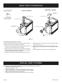
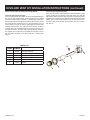
REAR VENT CONVERSION
HORIZONTAL VENTING
VERTICAL VENTING
Note: It is recommended that the
flue cover plate tab be pulled
outward prior to removal.
INLET VENT
COVER PLATE
INLET VENT COLLAR
This will ensure that the plate
is not accidentally dropped
inside the rear air chamber.
FLUE COVER PLATE
FLUE OUTLET COLLAR
FLUE COVER PLATE
(See note above.)
FLUE OUTLET COLLAR
INLET VENT COLLAR
INLET VENT
COVER PLATE
Figure 11
&RQYHUWLQJÀXHWDNHRIIWRUHDUYHQWLQJ
:KHQVZLWFKLQJRXWWKHÀXHDQGLQOHWYHQWFROODUVWRUXQKRUL]RQWDOO\
off the rear vent, the following steps must be taken.
5HPRYHWKHLQOHWYHQWFROODUVFUHZVDQGÀXHFROODUVFUHZV
IURPWKHWRSRIWKH¿UHSODFHDQGVHWWRWKHVLGH
5HPRYH WKH LQOHW FRYHU SODWH VFUHZV DQG ÀXH FRYHU SODWH
VFUHZVORFDWHGRQWKHEDFNRIWKH¿UHSODFH7KHVHZLOOEH
XVHGWRFORVHWKHWRSÀXHDQGLQOHWRSHQLQJV
,QVWDOOÀXHFRYHUSODWHRYHUWKHWRSÀXHRSHQLQJZLWKVFUHZV
4. Reinstall the inlet cover plate over the top inlet opening with 4
screws. See Figure 11.
,QVWDOOWKHÀXHFROODUDVVHPEO\WRWKHUHDUÀXHZLWKVFUHZV
,QVWDOO WKH LQOHW YHQW FROODU WR WKH UHDU RI WKH ¿UHSODFH ZLWK screws.
7. This completes the conversion for a rear vent application.
SPECIAL VENT SYSTEMS
7KHIROORZLQJYHQWV\VWHPVDUHDFFHSWDEOHIRUXVHZLWKWKH'936333VHULHV¿UHSODFHV
6LPSVRQ'XUDYHQW3526HULHVǫ
6HONLUN'LUHFW7HPSǫ
0HWDO)DE6XUHVHDO1RWH$GDSWHUSLSHVWDUWHUUHTXLUHG
(PSLUH+RUL]RQWDO5RXQG7HUPLQDWLRQ.LW'99.5(UHIHUWRSDJH
(PSLUH)OH[YHQW.LW'99.)UHIHUWRSDJH
(PSLUH)OH[YHQW.LW'99.)99HUWLFDO)OH[9HQW.LWUHIHUWRSDJH
Page 14
30786-0-0712
PLANNING INSTALLATION
,Q SODQQLQJ WKH LQVWDOODWLRQ IRU WKH ¿UHSODFH LW LV QHFHVVDU\ WR
determine where the unit is to be installed and whether optional
accessories are desired. Gas supply piping should also be planned
at this time. A gas shutoff must be installed in this line.
,IWKH¿UHSODFHLVLQVWDOOHGGLUHFWO\RQFDUSHWLQJWLOHRURWKHU
FRPEXVWLEOHPDWHULDORWKHUWKDQZRRGÀRRULQJLWVKRXOGEH
installed on a metal or wood panel extending the full width
and depth of the unit.
7KH¿UHSODFHFDQEHPRXQWHGRQDQ\RIWKHVHVXUIDFHV
$ÀDWKDUGFRPEXVWLEOHRUQRQFRPEXVWLEOHVXUIDFH
2. A raised platform of combustible or non-combustible material.
)RXUFRUQHUVRIWKH¿UHSODFHVRFRQWDFWLVPDGHRQDOOIRXU
perimeter edges on the bottom of the unit.
(Example: Four (4) concrete masonry blocks.)
At this point, you should have decided what components to include
LQ\RXULQVWDOODWLRQDQGZKHUHWKH¿UHSODFHLVWREHORFDWHG,IWKLV
has not been done, stop and consult your dealer for assistance
with this planning.
Accessory kits such as the FBB5 Blower kit, Trim kits, Mantles, plus
other Decorative Frame, Hood, and Door accessory kits may be
LQVWDOOHGDIWHUWKH¿UHSODFHLVVHFXUHGWRWKHIUDPLQJ
Refer to the instructions provided with each of the optional accessory
kits for proper installation and operation.
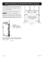
FIREPLACE INSTALLATION INSTRUCTIONS
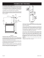
Fireplace Framing
)UDPLQJFDQEHEXLOWEHIRUHRUDIWHUWKH¿UHSODFHLVVHWLQSODFH
Framing should be constructed to accommodate wall covering and
¿UHSODFHIDFLQJPDWHULDO7KH¿UHSODFHIUDPLQJVKRXOGEHFRQVWUXFWHG
of 2 x 4 lumber or heavier. The framing headers may rest on the top
standoff spacers. Refer to Figure 12 for framing dimensions.
Note: On Peninsula models, a maximum weight of 250 lbs. must
not be exceeded when construction materials are supported by the
top standoff spacers.
A
C
B
Framing - Peninsula
Fireplace Framing Dimensions (in inches)
"A"
"B"
"C"*
Model
Framing
Height
Framing
Width
Framing
Depth
DVP36SP
41 1/2"
40"
23"*
DVP36PP
41 1/2"
39"**
23"*
Attention: Add height of base to "A" Dimension when elevatLQJ¿UHSODFHLILQVWDOOLQJRQDQHOHYDWHGEDVH
Framing dimension A includes a three inch clearance for
VWDQGRIIVRQWRSRI¿UHSODFH
'LPHQVLRQ&DVVXPHVXVHRIZDOOERDUGÀXVKWRERWK
front faces.
** Peninsula model framing width assumes use of 1/2" wall
ERDUGÀXVKWRWKHHQGIDFH
A
C
B
Framing - See-Through
Figure 12
30786-0-0712
Page 15
FIREPLACE INSTALLATION INSTRUCTIONS (continued)
Locating Fireplace
$WWDFK WKH IUDPLQJ EUDFNHWV WR WKH ¿UHSODFH SODFH ¿UHSODFH LQ
framed opening and secure to framing. Different hole locations can
EHXVHGIRU¿QLVKLQJPDWHULDOVZLWKWKLFNQHVVHVRIDQG
3/4". Secure the brackets with screws provided using two (2) per
framing bracket. See Figure 13.
)UDPLQJEUDFNHWVVKRXOG¿WGLUHFWO\DJDLQVWIUDPLQJPDWHULDO8VH
at least one (1) nail or screw per bracket to secure in place.
IMPORTANT!&KHFNVTXDUHQHVVRIDOORSHQLQJVRIWKH¿UHSODFH
prior to securing to the framed openings. See Figure 14.
NOTICE: 7KHIUDPLQJEUDFNHWVDUHVKLSSHGDVÀDWEUDFNHWVWKDWFDQ
EHDWWDFKHGWRWKHHQGVRIWKH¿UHSODFHSULRUWRVOLGLQJ¿UHSODFHLQWR
IUDPHGRSHQLQJ2QFHWKH¿UHSODFHLVVOLGLQWRSRVLWLRQWKHIUDPLQJ
brackets can be hand formed to overlap the framing, then secured to
WKHIUDPLQJRQFHWKH¿UHSODFHLVVTXDUHGXSDVVKRZQLQ)LJXUH
FIREPLACE OPENING
CHECK TO SEE
THAT BOX IS SQUARE
PRIOR TO ATTACHING TO
FRAMING
Figure 14
ATTACH 4
)(
FRAMING BRACKETS
TO SID
E(S) OF FIREPLACE
PRIOR TO INSTALLING
UNIT TO FRAMED OPENING
NOTE: On See-Through models, the framing brackets may be
LQVWDOOHGRQWKH¿UHSODFHLQWKHÀDWVWDWH2QFHWKH¿UHSODFHLVSODFHG
into the framed opening, the brackets can be hand bent over the
framing and secured.
Figure 13
Page 16
30786-0-0712
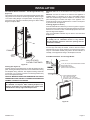
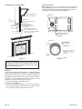
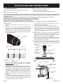
INSTALLATION
Flush Mount Mantel Installation - See-through Models Only
(Figure 15)
7KH¿UHSODFHPXVWH[WHQGEH\RQG¿QLVKHGZDOOVXUIDFHZKHQ
XVLQJDÀXVKPRXQWPDQWHORQVHHWKURXJKPRGHOV5HIHUWR)LJXUH
WRORFDWHQDLOLQJÀDQJHVRQ¿UHSODFHVLGHV8VHHLJKW
hex-head screws supplied in hardware package to attach nailing
ÀDQJHVWR¿UHSODFHVLGHV
Attention:$GGWR³$´GLPHQVLRQVZKHQXVLQJDÀXVKPDQWHO
base.
Attention: If a base or mantel is not used and the appliance is
installed directly on carpeting, tile or other combustible material
RWKHUWKDQZRRGÀRRULQJLWVKDOOEHLQVWDOOHGRQDPHWDORUZRRG
panel extending the full width and depth of the appliance. The
vertical dimension must be adjusted when a metal or wood panel
is placed beneath the appliance.
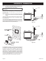
Finishing (Figures 16 and 17)
Finish the walls with the material of your choice. Figure 3 on page 10
shows the minimum vertical and corresponding maximum horizontal
dimensions of mantels or other combustible projections above the
WRSIURQWHGJHRIWKH¿UHSODFH
Only non-combustible materials may be used to cover the black
¿UHSODFHIURQW
:DUQLQJ :KHQ ¿QLVKLQJ WKH ¿UHSODFH QHYHU REVWUXFW
or modify the air inlet/outlet louvers in any manner.
Provide adequate clearances around air openings into the
combustion chamber.
Caution:,IWKHMRLQWVEHWZHHQWKH¿QLVKHGZDOODQGWKH¿UHSODFH
surround (top and sides) are sealed, a 300°F minimum sealant
material must be used. These joints are not required to be sealed.
Only non-combustible material (using 300°F minimum adhesive if
QHHGHGFDQEHDSSOLHGDVIDFLQJWRWKH¿UHSODFHVXUURXQG
FRAMING
Flush Wall Installation - See Through Models
NAIL OR OTHER
SUITABLE FASTENER
Figure 15
Framing (See Figure 12)
)LUHSODFHIUDPLQJFDQEHEXLOWEHIRUHRUDIWHUWKH¿UHSODFHLVVHWLQ
place. Framing should be positioned to accommodate wall covering
DQG ¿UHSODFH IDFLQJ PDWHULDO 7KH ¿UHSODFH IUDPLQJ VKRXOG EH
constructed of 2 x 4 lumber or heavier. The framing headers may
UHVWRQWKH¿UHSODFHVWDQGRIIV
CAUTION: MEASURE FIREPLACE DIMENSIONS AND VERIFY
FRAMING METHODS, AND WALL COVERING DETAILS BEFORE
FRAMING CONSTRUCTION BEGINS.
FINISHED WALL
6 3/8” (162 mm) OF NON-COMBUSTIBLE MATERIA
FRONT TRIM OR NONCOMBUSTIBLE MA TERIAL
(INSTALLA TION IS OPTIONAL)
JOINT BETWEEN FINISHED
WALL AND UNIT SEALED
WITH 300° F, 149° C SEALANT
MATERIAL (SEALANT IS OPTIONAL)
Framing dimension "A" (Figure 12) includes the clearance
IRU VWDQGRIIV RQ ¿UHSODFH $IWHU LQVWDOOLQJ ¿UHSODFH LQWR
IUDPLQJ WKH ¿QLVKHG QRQFRPEXVWLEOH ZDOO VXUIDFH PXVW
H[WHQGGRZQWRWKHWRSHGJHRIWKH¿UHSODFHIDFH
Figure 16
30786-0-0712
Page 17
Vent Pipe Clearance
Note: Maintain one inch (1") of clearance around vertical vent
pipe. See Figure 18. For horizontal vent, maintain a minimum 1"
clearance to the bottom and sides of the vent, and 3" clearance to
combustibles above the vent pipe. See Figure 19.
Combustible Surround Installation
MANTELSHELF
VENT PIPE
COMBUSTIBLE SURROUND
2X4
HEADER
STAND OFF
FINISHED WALL
6 3/8
”O F NON-COMBUSTIBLE
MATERIAL
FRONT TRIM OR
NON-COMBUSTIBLE
MATERIAL (INSTALLATION
IS OPTIONAL)
OINT BETWEEN FINISHED
J
WALL AND UNIT SEALED WITH
300°F (14
°C)
9
SEALANT MATERIAL
(SEALANT IS OPTIONAL)
1” MINIMUM CLEARANCE
AROUND VENT PIPE
Figure 18
Figure 17
Figure 19
Attention: Cold climate installation recommendation: When
installing this unit against a non-insulated exterior wall, it is
recommended that the outer walls be insulated to conform
to applicable insulation codes.
Vent Runs
,QSODQQLQJWKHLQVWDOODWLRQIRUWKH¿UHSODFHLWLVQHFHVVDU\WRLQVWDOO
certain components before the appliance is completely positioned
and installed. These include the direct vent system, gas piping for
the appliance and the electrical wiring. (If the fan option is used.)
In addition to non-combustible surfaces, the appliance can be
mounted on any of the following surface options:
$ÀDWKDUGFRPEXVWLEOHEXUQDEOHVXUIDFH
2. A raised wooden platform.
3. Four (4) corner supports. (Example: Four (4) concrete masonry
blocks.) These supports must be positioned so they contact all
four (4) perimeter edges on the bottom of the unit.
Page 18
30786-0-0712
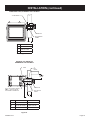
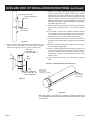
INSTALLATION (continued)
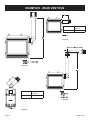
HORIZONTAL ONLY, STRAIGHT OUT THE BACK
“A” PIPE LENGTH
VENT CAP
WALL FIRESTOP/
THIMBLE
“B”
"A"
"B"
6"
5 1/8" to 6 1/2"
9"
8 1/8" to 9 1/2"
12" 11 1/8" to 12 1/2"
Figure 20
VERTICAL, 90° ELBOW TO
HORIZONTAL OUT THE WALL
“A”
PIPE
LENGTH
90º ELBOW
”9 (29 MM)
MINIMU
M
VENT CAP
NOTE:1 FOOT VERTICAL VENT (MIN.)
REQ
IRED WHEN TOP VENTING
U
WITH HORIZ
ONT AL TERMINATION
WALL FIRESTOP/
THIMBLE
“C”
“B”
"A"
6"
"B"
11 1/4" to 12 3/4"
"C"
4 3/4" to 6 1/4"
9"
14 1/4" to 15 3/4"
7 3/4" to 9 1/4"
12"
17 1/4" to 18 3/4"
10 3/4" to 12 1/4"
Figure 21
30786-0-0712
Page 19
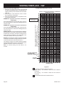
VENTING FIREPLACE - TOP
EXAMPLE A: (Top Vent Connections with Vertical
Termination).
,IWKHYHUWLFDOGLPHQVLRQIURPWKHÀRRURIWKHXQLWLV
IHHWWKHKRUL]RQWDOUXQWRWKHRXWHUZDOOÀDQJHPXVWQRW
exceed 6.5 feet.
EXAMPLE B: (Top Vent Connections with Vertical
Termination)
,IWKHYHUWLFDOGLPHQVLRQIURPWKHÀRRURIWKHXQLWLV
IHHWWKHKRUL]RQWDOUXQWRWKHRXWHUZDOOÀDQJHPXVWQRW
exceed 14.5 feet.
SPECIAL NOTE: For each 45 degree elbow installed in
the horizontal run, the length of the horizontal run MUST
be reduced by 18" (45cm). This does not apply if the 45
degree elbows are installed on the vertical part of the
vent system. Reduce 3' for every 90° elbow.
Example: According to the chart the maximum horizontal
vent length is 20' and if two 45 degree elbows are required
in the horizontal vent it must be reduced to 17'.
The maximum number of 45 degree elbows permitted
per side wall installation is two (2). These elbows can be
installed in either the vertical or horizontal run.
Note: On vertical venting the first elbow is not
counted.
Venting Graph (Dimensions in Feet)
TOP EXIT - VERTICAL AND HORIZONTAL TERMINATION
(DIMENSIONS IN FEET)
NOTE: FLEX VENT
MAXIMUM HEIGHT
IS 35 FEET
VERTICAL DIMENSION FROM THE BOTTOM OF THE UNIT
TO THE CENTER OF THE FLUE OUTLET
WITH VERTICAL OR HORIZONTAL TERMINATION CAPS
To Use the Vent Graph (Figure 22)
1. Determine the height of the center of the horizontal
vent pipe. Using this dimension on the Sidewall Vent
Graph, locate the point it intersects with the slanted
graph line.
2. From the point of this intersection, draw a vertical
line to the bottom of the graph.
3. Select the indicated dimension, and position the unit
in accordance with same.
TOP VENT CONNECTION
OF VENTING WITH
HORIZONTAL TERMINATION
TOP VENT
CONNECTION
HORIZONTAL RUN
Figure 22
Acceptable vertical and horizontal vent run.
Rigid Venting - 40' maximum vertical and 20' maximum
horizontal
Flex Venting - 35' maximum vertical and 20' maximum
horizontal
Unacceptable vertical and horizontal vent run.
Page 20
30786-0-0712
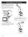
VENTING FIREPLACE - TOP (continued)
Below Grade Installation
When it is not possible to meet the required vent terminal clearances
of 12" (305mm) above grade level, a snorkel kit is recommended.
See page 38. It allows installation depth down to 7" (178mm) below
grade level. The 7" (178mm) is measured from the center of the
horizontal vent pipe as it penetrates through the wall.
Ensure the sidewall venting clearances are observed. If venting
system is installed below ground, we recommend a window well
with adequate and proper drainage to be installed around the
termination area.
FIRESTOP AT
CEILING LEVEL
COMBUSTIBLE
PROJECTION
3” (76mm)
MINIMUM
18” (457mm)
MINIMUM
PIPE STRAP
12” (305mm)
ABOVE GRADE
48”
(1219mm)
SEE GRAPH FOR PERMISSIBLE “H” AND “V” DIMENSIONS
Figure 24
Examples of possible venting systems using two (2) 90° elbows.
V is listed as minimum vertical dimensions and H1 + H2 is listed
as total of maximum horizontal dimensions. The maximum vertical
and horizontal distances for two (2) 90° elbows as shown in Figure
25 is 20 feet.
Attention: Refer to Figure 22 for additional venting requirements.
TYPICAL BASEMENT INSTALLATION
Figure 23
Examples of possible venting systems using one (1) 90° elbow.
Eight (8) feet is listed as minimum vertical vent run with 20 feet of
maximum horizontal vent run. Vertical dimensions are based on
centerline to centerline of pipe. Horizontal dimensions are based
on centerline of pipe to end of termination.
1
FIRESTOP AT
CEILING LEVEL
SEE GRAPH FOR PERMISSIBLE “H” AND “V” DIMENSIONS
NOTE: H1 AND H2 MU
ST BE ADDED TOGETHER TO U
SE CHART
Figure 25
30786-0-0712
Page 21
10”
(254mm)
C
SEE VENT CHART
FOR PERMISSIBLE
“H” AND “V”
DIMENSIONS
11”
(279mm)
VENT CAP
B
V
H
1 FOOT VERTICAL
PIPE REQUIRED
(MINIMUM)
C
B
9” (229 MM)
MINIMUM
A
CENTER OF ELBOW
STRAIGHT OUT
(MINIMUM)
NOTE: 1 FOOT SECTION (MIN.)
OF VERTICAL VENT REQUIRED
WHEN USING HORIZONTAL
TERMINATION OFF TOP.
Figure 27
2’ MAX
.
(6
09.6
mm)
Figure 26
MINIMUM HOLE LOCATION DIMENSIONS FOR THROUGH
THE WALL HORIZONTAL INSTALLATIONS WITH 90 DEGREE
ELBOW AND 1' VERTICAL VENT OFF TOP OF FIREPLACE
MAX
IMUM HORIZ
ONT AL
RUN WITH 1 FOOT VERTICAL
RISE AND 90° ELBOW
FIREPLACE
SERIES
HARD ELBOW DIMENSIONS
"A"
"B"
"C"
DVP36(SP,PP)
53"
4 1/2"
6 1/2"
(1346.2mm) (114.3mm) (165.1mm)
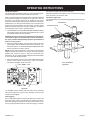
Positioning the Fireplace
Determine the exact position of the appliance so the direct vent
termination will be centered (if possible) between two (2) studs. This
will avoid any extra framing. All vent kit pipes should be assembled
RQWKHXQLWDIWHUWKHXQLWLVPRYHGLQWRWKH¿QDOSRVLWLRQ
Cutting the Hole (Figures 26)
$IWHUWKH¿UHSODFHKDVEHHQSRVLWLRQHGLQLWVSHUPDQHQWORFDWLRQ
the hole through the exterior wall of the house can be cut. This hole
must be 11" (279.4 mm) high x 10" (254mm) wide with its center
line determined by the amount of vertical rise and horizontal run of
the termination. See Figure 26.
When locating the hole it must be noted that the bottom of the cap
must be 12" (305mm) above the ground level, and top of the cap
must be no less than 18" (457mm) below a combustible projection,
and no closer than 9" (229mm) to any wall running parallel to vent
termination. See Figure 27.
MAX
IMUM HORIZ
ONT AL
RUN WITH MINIMUM
VERTICAL RISE AND
90° ELBOW
20’ (6
.1m)
PIPE STRAPS
EVERY3 ’ (91c
m)
’8 (244c
m)
TO BOTTOM
OF UNIT
Figure 28
Page 22
30786-0-0712
DVVK-4FV DIRECT VENT TERMINATION KIT
Installation Instructions
7KLVWHUPLQDWLRQNLWFDQRQO\EHXVHGZLWK(PSLUH&RPIRUW6\VWHPVGLUHFWYHQW¿UHSODFHVOLVWHGIRUXVHZLWK
'99.)99HUWLFDO)OH[9HQW.LW3OHDVHUHYLHZWKHLQVWUXFWLRQVSDFNDJHGZLWK\RXU¿UHSODFHDQGYHULI\WKH
¿UHSODFHPRGHOQXPEHU&KHFNWKDWWKLVÀH[YHQWV\VWHPLVOLVWHGIRUXVHZLWK\RXU¿UHSODFHPRGHOSULRUWR
starting the installation.
This vent kit may be installed as an OEM installation in a manufactured home (USA only) or mobile
home and must be installed in accordance with the manufacturer’s instructions and the manufactured
home construction and safety standard, Title 24 CFR, Part 3280 or Standard for Installation in Mobile
Homes, CAN/CSA Z240 MH.
CAUTION
All Fireplaces listed for use with the DVVK-4FV will operate safely when installed in accordance with this instruction manual. Read all
LQVWUXFWLRQVEHIRUHVWDUWLQJLQVWDOODWLRQWKHQIROORZWKHVHLQVWUXFWLRQVFDUHIXOO\WRPD[LPL]H¿UHSODFHSHUIRUPDQFHDQGVDIHW\5HSRUW
damaged parts to your dealer.
WARNING
Any common venting of the gas appliance using the DV vent kit with other gas appliances is not allowed. Do not connect this appliance
WRDFKLPQH\ÀXHVHUYLFLQJDVHSDUDWHVROLGIXHOEXUQLQJDSSOLDQFH
WARNING
)DLOXUHWRIROORZWKHVHLQVWUXFWLRQVPD\FUHDWHDSRVVLEOH¿UHKD]DUGDQGZLOOYRLGWKHZDUUDQW\
WARNING
Always maintain minimum clearances around vent systems. The minimum clearance to combustibles for horizontal runs of vent pipe is
LQFKHVIURPWKHWRSDQGLQFKIURPWKHVLGHVDQGERWWRPRIWKHYHQWV\VWHP'RQRWSDFNWKHRSHQDLUVSDFHVDURXQGWKH¿UHSODFHRU
ÀXHZLWKLQVXODWLRQRURWKHUPDWHULDOV$Q\KRUL]RQWDOUXQPXVWKDYHD´ULVHIRUHYHU\RQHIRRWRIUXQWRZDUGVWKHYHQWWHUPLQDWLRQ
The vent above the roof must terminate vertically.
WARNING
&RQWDFW\RXU/RFDO%XLOGLQJDQG)LUH2I¿FLDOVDERXWUHVWULFWLRQVDQGLQVWDOODWLRQLQVSHFWLRQVLQ\RXUDUHD
IMPORTANT SAFETY INFORMATION
7KHYHUWLFDOWHUPLQDWLRQFDS0867EHYHQWHGGLUHFWO\WRWKH
outside. The termination kit MUST NEVER be connected to a
FKLPQH\ÀXHVVHUYLFLQJDVHSDUDWHVROLGIXHOEXUQLQJDSSOLance or any other appliances.
7HUPLQDWLRQFDS0867127EHPRXQWHGKRUL]RQWDOO\
7KHÀH[LEOHYHQWSLSHFDQQRWEHLQWHUPLQJOHGZLWKDQ\RIWKH
rigid vent pipe section(s). DO NOT connect two sections of
ÀH[LEOHYHQWSLSHWRJHWKHUWRDFKLHYHDORQJHUOHQJWKZLWKRXW
the use of approved connectors.
7KHLQVWDOODWLRQ PXVWFRQIRUPZLWKORFDOFRGHVRULQWKHDEsence of local codes, with the National Fuel Gas Code, ANSI
Z223.1 (in the United States) or with the current installation
code CAN/CGA B149 (in Canada).
2QO\ 'LUHFW 9HQW ¿UHSODFHV DSSURYHG IRU XVH ZLWK (PSLUH
Comfort Systems, Inc. DVVK-4FV termination kit shall be
used. See PARTS LIST/ILLUSTRATIONS section for vent
FRPSRQHQWLGHQWL¿FDWLRQ
30786-0-0712
+RUL]RQWDO YHQW UXQV PXVW EH VXSSRUWHG HYHU\ IHHW XVLQJ
wall straps. Vertical runs must be supported every 3 feet using
wall straps. Slip wall straps loosely on to pipe. Attach installer
provided straps to framing members using nails or screws.
7KH¿UHSODFHDQGYHQWLQJV\VWHPVKRXOGEHLQVSHFWHGEHIRUH
LQLWLDOXVHDQGDWOHDVWDQQXDOO\E\DTXDOL¿HG¿HOGVHUYLFHSHUson. Inspect the external vent cap on a regular basis to make
VXUHWKDWQRGHEULVLVLQWHUIHULQJZLWKWKHDLUÀRZ,QVSHFWHQWLUH
venting system to ensure proper function.
3OHDVH UHIHU WR WKH ¿UHSODFH LQVWUXFWLRQV IRU LQIRUPDWLRQ RQ
Termination Cap clearances.
Page 23
PRE-INSTALLATION INFORMATION:
Items Required For Installation:
Tools
Building Supplies
Phillips Screwdriver
Hammer
Saw and/or saber saw
Level
Measuring Tape
Electric Drill and Bits
Pliers
Square
Tin Snips
Framing Materials
Wall Finishing Materials
Caulking Material (Noncombustible)
Support Strap supplies
Before You Start:
3ODQ\RXULQVWDOODWLRQ5HDGWKHVHLQVWUXFWLRQVDQGWKH¿UHSODFHLQVWDOODWLRQPDQXDOEHIRUHLQVWDOOLQJXQLWDQGYHQWV\VWHP
6HWXQLWLQSODFHDQGVXUYH\KRZEHVWWRYHQWWKHXQLW$IWHUWKHYHQWFRQ¿JXUDWLRQKDVEHHQGHFLGHGVWUHWFKWKHÀH[SLSH
components out, then trim off what will not be needed.
5HIHUWRWKH¿UHSODFHLQVWDOODWLRQPDQXDOIRULQIRUPDWLRQRQYHUWLFDOYHQWLQJUHTXLUHPHQWV7KHPD[LPXPOHQJWKRIYHQWZKHQ
XVLQJÀH[YHQWLQJLVIHHWWRWDO&RQWDFW\RXUGHDOHURUGLVWULEXWRUIRULQIRUPDWLRQRQÀH[YHQWH[WHQVLRQNLWVWKDWPD\EH
DGGHGWRWKH'99.)9NLWLQRUGHUWRWHUPLQDWHXSWRIHHW$YDLODEOHH[WHQVLRQNLWVLQFOXGHWKH'9(.¶)OH[RU
WKH'9(.¶)OH[H[WHQVLRQNLWV7KHH[WHQVLRQNLWVLQFOXGHFRQQHFWLRQKDUGZDUH
Installation of the Vertical Flex Termination Kit
WARNING
Ensure that the venting system exits the structure through the roof and does not terminate less than 12 inches (305mm) above the
roof.
WARNING
5HIHUWR\RXU¿UHSODFHKRPHRZQHU¶VPDQXDOIRUWKHPLQLPXPDQGPD[LPXPYHQWLQJUHTXLUHPHQWRI\RXU¿UHSODFHSULRUWRLQVWDOODWLRQ
)DLOXUHWRGRVRPD\FDXVHD¿UHKD]DUG
WARNING
7KLVÀH[LEOHSLSHWHUPLQDWLRQNLWLV21/<IRUYHUWLFDOWHUPLQDWLRQV
WARNING
Any horizontal run section must have a 1/4” rise for every one (1) foot of run towards the vent termination. Never allow the vent pipe to
UXQGRZQZDUG7KLVFRXOGFDXVHKLJKWHPSHUDWXUHVDQGPD\SUHVHQWD¿UHKD]DUG7KLVYHUWLFDONLWPD\LQFRUSRUDWHWZRGHJUHH
bends, but must terminate vertically.
CAUTION
7KLVÀH[YHQWNLWFDQEHLQVWDOOHGHLWKHUYHUWLFDOO\RUKRUL]RQWDOO\RIIRI'LUHFW9HQW6HULHV¿UHSODFHVEXWPXVWRQO\WHUPLQDWHYHUWLFDOO\
WARNING
%HFDXVHRIVKDUSHGJHVDOZD\VXVHJORYHVZKHQKDQGOLQJWKHÀH[YHQWFRPSRQHQWV
CAUTION
Vent connections should overlap a minimum of 1” for proper sealing.
CAUTION
$OZD\VVWUHWFKDQGVHFXUHYHQWLQJZLWKPHWDOVWUDSSLQJVHFXUHGZLWKQDLOVQDLOVDQGVWUDSSLQJQRWVXSSOLHGWRHQVXUHWKDWWKHÀH[YHQW
runs remain true.
INSTALLATION NOTE:
,IVSDFHSHUPLWVLWLVJHQHUDOO\HDVLHUWRDWWDFKYHQWLQJLQWKHWRSYHQWFRQ¿JXUDWLRQ
Page 24
30786-0-0712
DVVK-4FV DIRECT VENT TERMINATION KIT (continued)
Step-By-Step Installation For Flex DV Kit
1.
Unpack vent components and check all items for shipping
damage.
2. For this venting system to operate as designed it is dependent
on the use of all parts and procedures detailed in these instructions. Failure to follow these instructions may potentially
affect the performance of this vent system and the attached
appliance.
$VSHUWKH¿UHSODFHPDQXIDFWXUHU¶VLQVWUXFWLRQVUHSODFHWKH
H[LVWLQJ ´ GLDPHWHU ¿UHSODFH YHQW DGDSWHU ZLWK WKH ´
GLDPHWHU ÀH[ YHQW ¿UHSODFH DGDSWHU LQFOXGHG LQ WKH YHQW NLW
Install the adapter collar with the screws removed from the
VWDQGDUG¿UHSODFHFROODU5HIHUWRWKH¿UHSODFHPDQXDOIRUDGditional information on the vent collar removal and installation.
2QFH WKH ¿UHSODFH ORFDWLRQ KDV EHHQ GHWHUPLQHG PDUN WKH
FHLOLQJZKHUHWKHÀH[YHQWZLOOSDVVWKURXJK&XWDQRSHQLQJ
IRULQVWDOODWLRQRIWKH¿UHVWRSWKLPEOHDVVHPEO\7KHRSHQLQJ
must measure a minimum of 9-1/2” x 9-1/2” square. See Figure 29.
Figure 29
30786-0-0712
5.
Next, determine the location for the cutout in the roof opening.
This opening must be large enough to provide a minimum 1”
air space clearance from the vertical vent pipe to any combustible framing.
6. Install the Firestop/Thimble assembly to the framed opening
in the ceiling using common nails or screws.
Note: The thimble assembly is adjustable up or down as
QHHGHGZLWKLQWKH¿UHVWRS,WLVDOVRGHVLJQHGZLWKDSLYRWLQJ
¿UHVWRSIRUXVHZLWKSLWFKFDWKHGUDOFHLOLQJV
7REHJLQYHQWV\VWHPDVVHPEO\¿UVWOD\RXWDOOWKHYHQWFRPSRQHQWVRQWKHÀRRULQWKHRUGHULQZKLFKWKH\ZLOOEHDVVHPbled.
6WUHWFKWKH´GLDPHWHULQQHUÀH[ÀXHDQG´GLDPHWHURXWHU
ÀH[YHQWWRWKHPD[LPXPOHQJWKRIIHHW
,QVWDOOWKHVSULQJVSDFHUVSURYLGHGDURXQGWKH´GLDPHWHUÀH[
ÀXHDWIRRWLQWHUYDOVWKHQVOLGHWKHÀXHSLSHZLWKVSDFHUVLQWR
WKH´GLDPHWHURXWHUÀH[YHQWSLSH0DNHVXUHWKHVSULQJVDUH
VSDFHGHYHQO\VWDUWLQJDWLQFKHVIURPWKH¿UHSODFHFROODU
See Figure 30.
Figure 30
Page 25
DVVK-4FV DIRECT VENT TERMINATION KIT (continued)
:LWKWKHÀH[YHQWDVVHPEO\DQGWKH´ORQJKDUGSLSHFRPSRQHQWVODLGRXWRQWKHÀRRUEHJLQVHFXULQJWKHVHSDUWVWRgether. First, apply a generous bead of silicone sealant to
WKH LQVLGH RI WKH ´ GLDPHWHU ÀH[ ÀXH QRW WKH HQG ZLWK WKH
SUHLQVWDOODHGFRQQHFWRUWKHQVOLGHWKHÀH[ÀXHRYHUWKH´
GLDPHWHUKDUGSLSHÀXH%HVXUHWRRYHUODSDWOHDVW´6Hcure this connection with a 4” diameter band clamp provided.
%HFDUHIXOQRWWRGDPDJHRUWHDUWKHÀH[ÀXHZKHQWLJKWHQLQJ
clamp.
5HSHDWWKHFRQQHFWLRQSURFHVVIRUWKHRXWHU´GLDPHWHUÀH[
vent to hard pipe connection. Use silicone sealant at this joint
also, overlap at least 1-1/4”, then secure the joint with the 7”
diameter band clamp provided. Be careful not to damage or
WHDUWKHÀH[YHQWSLSHZKHQWLJKWHQLQJWKHFODPS
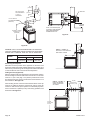
:KLOHWKHYHQWLQJLVVWLOORQWKHÀRRUDVVHPEOHWKHURRIMDFN
components as shown in Figure 31 and pre-install the roof
jack assembly to the hard pipe approximately 18” from the top
end of the hard pipe.
13. Now the pre-assembled vent system may be carried to the
roof, then lowered through the roof cutout opening (see step
)HHGWKHÀH[YHQWHQGGRZQWKURXJKWKHURRIRSHQLQJDQG
¿UHVWRSWKLPEOHDVVHPEO\LQVWDOOHGLQVWHSVWKURXJK
14. Secure the roof support assembly to the roof sheathing with
at least (4) nails/screws through each support bracket. Check
that the combustible clearances through the roof framing will
maintain at least a 1” clearance from the vent pipe.
15. Determine how high the vent terminal should be located
above the roof line based on the roof pitch information shown
in Figure 32. Adjust the vent system height by loosening the
pre-installed roof support pipe clamp and sliding the vent pipe
up or down as pre-determined, then re-tighten the pipe clamp.
Install a couple of sheet metal screws through the pipe clamp
into the outer hard vent pipe to lock in place.
&KHFN WR PDNH VXUH WKDW WKH ERWWRP HQG RI WKH ÀH[ YHQW LV
ORQJHQRXJKWRUHDFKWKH¿UHSODFHDGDSWHUFROODUV,IWRRORQJ
WULPRIIWKHH[WUDÀH[YHQWQRWQHHGHG
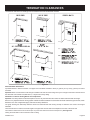
LOWEST
DISCHARGE
OPENING
VENT CAP
PIPE CLAMP
GAS VENT
H
ROOF BRACKET (2
)
X
12
WING NUT (2
)
ROOF PITCH IS X/12
NUT (2
)
H (Min
.) - Min
u
im
fr
o
to lo
st
e
w
e
rg
a
isch
d
SCREW (2
)
ROOF PITCH
Figure 31
t
h
ig
e
m
fro
ig
n
e
p
o
H (Min.)
Flat to 6/12
12” (305mm)
6/12 to 7/12
15” (381mm)
Over 7/12 to 8/12
18” (457mm)
Over 8/12 to 16/12
24” (610mm)
Over 16/12 to 21/12
36” (914mm)
Figure 32
Page 26
30786-0-0712
DVVK-4FV DIRECT VENT TERMINATION KIT (continued)
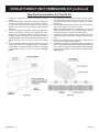
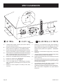
7RDWWDFKWKHYHQWFRQQHFWLRQVDWWKH¿UHSODFHEHVXUHWKH´
diameter adapter collar has been installed per step 3. Apply a
EHDGRIVLOLFRQHVHDODQWWRWKH´GLDPHWHUÀH[FRQQHFWRUWKHQ
VOLGHWKHÀH[SLSHDGDSWHUFROODULQWRWKH¿UHSODFHÀXHFROODU
and secure by installing a minimum of two (2) screws through
WKHÀXHFROODUDQGLQWRWKHDGDSWHUSee Figure 33.
18. Apply sealant to the 7” diameter adapter collar, slide outer
ÀH[YHQWRYHUWKHFROODUWKHQVHFXUHZLWKD´GLDPHWHUEDQG
clamp. See Figure 33.
2QFH WKH ORZHU FRQQHFWLRQV DUH PDGH DQG WKH ÀH[ SLSH LV
secured with support bands as required (3 feet minimum beWZHHQVXSSRUWVWKHQWKHURRIÀDVKLQJFDQEHLQVWDOOHG See
Figure 34.
,QVWDOOWKHURRIÀDVKLQJDQGVHDOXVLQJFRPPRQFRQVWUXFWLRQV
practices.
21. An additional storm collar band is provided in kit that may be
used as an attic insulation shield. The collar can be installed
DURXQG WKH ÀH[ SLSH RU KDUG SLSH MXVW DERYH WKH ¿UHVWRS
thimble. This collar will act as a shield to prevent blown insulation from entering the thimble.
22. To complete the vent installation, install the vent termination
cap to the top of the hard vent pipe assembly. Mate up the
ÀXHDQGRXWHUWHOHVFRSHVZLWKWKHKDUGSLSHDVVHPEO\WKHQ
secure by installing a minimum of two (2) sheet metal screws
LQWRWKHRYHUODSSHGÀDQJHVRIWKHFDSDQGSLSH
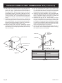
23. Figure 35 shows a completed installation with components
LGHQWL¿HG DQG RWKHU LQVWDOODWLRQ LQIRUPDWLRQ VXFK DV KHLJKWV
and clearance to combustibles.
Ve
t
n
Ca
p
7"(178
)
m
Dia
.
Ha
rd Pip
e
Mu
t Ex
s
d
n
te
Th
h
g
u
ro
Ro
f
o
Fls
g
in
h
a
Sto
rm
Co
r
la
Ro
f
o
Fla
g
in
h
s
Ro
f
o
Ex
rio
te
Ro
f
o
Su
rt
o
p
As
ly
b
m
e
s
7"(178
)
m
Dia
.
Fle
x
1” (2
5m
)
Min
u
im
Cle
c
rn
a
Co
tile
s
u
b
m
to
Figure 33
Figure 34
30786-0-0712
Page 27
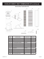
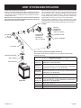
DVVK-4FV DIRECT VENT TERMINATION KIT (continued)
VERTICAL TERMINATION
STORM COLLAR
4’ LONG RIGID PIPE
ROOF FLASHING
ADJUSTABLE
ROOF JACK
ASSEMBLY
CLEARANCE TO
COMBUSTIBLES
REQUIRED FROM
VENT PIPE
ADJUSTABLE
FIRESTOP/THIMBLE
ASSEMBLY
ROOF EXTERIOR
CLAMPS AT FLUE &
INLET VENT CONNECTIONS
STORM COLLAR (USE TO
KEEP INSULATION OUT OF
THIMBLE ASSEMBLY)
CEILING
FIRESTOP/THIMBLE
VENTING SUPPORT
STRAPS (AS REQ’D)
35’ MAX
NOTE: DVVK-4FV KIT
MAXIMUM HEIGHT
(INCLUDING FIREPLACE) IS
13’. TO EXTEND VENT RUN,
AN ADDITIONAL VENT
EXTENSION KIT IS
NECESSARY
4” DIA. FLUE CONNECTOR
7” DIA. ADAPTER COLLAR
WITH GASKET & CLAMPS
SEE-THRU DIRECT VENT FIREPLACE
Figure 35
Page 28
30786-0-0712
DVVK-4FV DIRECT VENT TERMINATION KIT (continued)
Vertical Flex Termination Kit
Item
Number
30786-0-0712
Item Description
Repair Part No.
Quantity
Supplied
1
4”/7” Vertical Termination Cap
MF100038
1
2
Roof Support Kit
MF100503
1
3
2 Ply Alum Flex 4” Diameter by 6 ft.
MF04ALA2F006
1
4
2 Ply Alum Flex 7” Diameter by 6 ft.
MF07ALA2F006
1
5
4”/7” x 48” Rigid Pipe Assembly
MF100554
1
6
Firestop Thimble Assembly
MF100124
1
7
Roof Flashing (0/12 to 6/12)
MF100091
1
8
7” Flex Adapter Collar with Gasket
MF100524
1
9
7” Storm Collar
MF100147
2
10
Spring Spacers
MF100548
5
N/S
Clamp 4” Diameter
MF100330
2
N/S
Clamp 7” Diameter
MF100534
2
N/S
#8 x 1/2” Self Drilling Screws
N/A
20
N/S
HT Silicone
N/A
1
N/S
#8 x 5/8” Self Drilling Screws
N/A
10
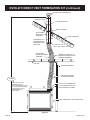
Page 29
EXAMPLES - TOP VENT RUN
24”
24” MINIMUM
CLEARANCE TO
COMBUSTIBLES
Example
H2 3ft, H3 1ft = 4ft
(90° + 90° + 90°) = 6ft
V1 = 21ft
H = 10ft
V = 21ft
Figure 37
Exa
le
p
m
H2 =2ft
2 - (90°+90°) =6ft
V1 =21ft
H =8ft
V =15ft
Figure 36
Exa
le
p
m
H1 =2ft
V1 =20ft
H =2ft
V =20ft
Figure 38
Page 30
30786-0-0712
VENTING FIREPLACE - REAR
EXAMPLE A:
,IWKHYHUWLFDOGLPHQVLRQIURPWKHÀRRURIWKHXQLWLV
12 feet, 4 inches the horizontal run to the outer wall
ÀDQJHPXVWQRWH[FHHGIHHWLQFKHV
EXAMPLE B:
,IWKHYHUWLFDOGLPHQVLRQIURPWKHÀRRURIWKHXQLWLV
6 feet, 9 inches, the horizontal run to the outer wall
ÀDQJHPXVWQRWH[FHHGIHHWLQFKHV
SPECIAL NOTE: For each 45 degree elbow installed
in the horizontal run, the length of the horizontal
run MUST be reduced by 18" (45cm). This does
not apply if the 45 degree elbows are installed on
the vertical part of the vent system. Reduce 3' for
every 90° elbow.
Example: According to the chart the maximum
horizontal vent length is 20' and if two 45 degree
elbows are required in the horizontal vent it must
be reduced to 17'.
The maximum number of 45 degree elbows permitted
per side wall installation is two (2). These elbows can
be installed in either the vertical or horizontal run.
Venting Graph (Dimensions in Feet)
REAR EXIT - VERTICAL AND HORIZONTAL TERMINATION
(DIMENSIONS IN FEET)
40
39
38
37
NOTE: FLEX VENT
MAXIMUM HEIGHT
IS 35 FEET
36
35
34
33
32
31
30
29
VERTICAL DIMENSION FROM THE BOTTOM OF THE UNIT
TO THE CENTER OF THE FLUE OUTLET
WITH VERTICAL OR HORIZONTAL TERMINATION CAPS
To Use the Vent Graph (Figure 39)
1. Determine the height of the center of the
horizontal vent pipe. Using this dimension on the
Sidewall Vent Graph, locate the point it intersects
with the slanted graph line.
2. From the point of this intersection, draw a vertical
line to the bottom of the graph.
3. Select the indicated dimension, and position the
unit in accordance with same.
28
27
26
A
B
REAR HORIZONTAL
VENT CONNECTION
HORIZONTAL RUN
Figure 39
Acceptable vertical and horizontal vent run.
Unacceptable vertical and horizontal vent run.
30786-0-0712
Page 31
EXAMPLES - REAR VENT RUN
Model
DVP36(SP,PP)
Maximum Pipe
Length H1
18"
H1 = 18” MAX.
Figure 42
Figure 40
Model
DVP36(SP,PP)
Maximum Pipe
Length H1
18"
Figure 43
H1 = 18 ch
sin
e
x
a
m
Figure 41
Page 32
30786-0-0712
TERMINATION CLEARANCES
Termination clearance for buildings with combustible and noncombustible exteriors.
Figure 44
Vertical Sidewall Installations
Important! Minimum clearance between vent pipes and combustible materials is three (3") (76mm) on top, and (1") (25mm) on bottom
and sides.
Important! When vent termination exits through foundation less than 20" below siding outcrop, the vent pipe must extend outward so that
WKHKRUL]RQWDOYHQWWHUPLQDOLVORFDWHGÀXVKWRRUEH\RQGWKHRXWFURSVLGLQJ
Information on Various Venting Routes and Components
Important:,WLVDOZD\VEHVWWRORFDWHWKH¿UHSODFHLQVXFKDZD\WKDWPLQLPL]HVWKHQXPEHURIRIIVHWVDQGKRUL]RQWDOYHQWOHQJWK
6LQFHLWLVYHU\LPSRUWDQWWKDWWKHYHQWLQJV\VWHPPDLQWDLQLWVEDODQFHEHWZHHQWKHFRPEXVWLRQDLULQWDNHDQGWKHÀXHJDVH[KDXVWFHUWDLQ
OLPLWDWLRQVDVWRYHQWFRQ¿JXUDWLRQVDSSO\DQGPXVWEHVWULFWO\DGKHUHGWR
The graph showing the relationship between vertical and horizontal side wall venting will help to determine the various vent lengths
allowable.
7KHKRUL]RQWDOYHQWUXQUHIHUVWRWKHWRWDOOHQJWKRIYHQWSLSHIURPWKHÀXHFROODURIWKH¿UHSODFHWRWKHIDFHRIWKHRXWHUZDOO
The maximum horizontal vent run is 20 feet (457 cm) when the vertical vent rise is 8 feet (244 cm). See Figure 22.
Venting terminals shall not be recessed into wall or siding.
30786-0-0712
Page 33
VENT CLEARANCES
Figure 45
A =
*Clearance above grade, veranda, porch, deck or balcony
[*12 inches (30cm) minimum]
B =
clearance to window or door that may be opened [*12 inches
(30cm) minimum for appliances < 100,000 Btuh (30kW)
C =
clearance to permanently closed window [minimum 12 inches
(30cm) recommended to prevent condensation on window]
J =
clearance to non-mechanical air supply inlet to building or
the combustion air inlet to any other appliance [*12 inches
FPPLQLPXPIRUDSSOLDQFHV%WXKN:
36 inches (90cm) minimum for appliances > 100,000 Btuh
(30kW)]
K =
' YHUWLFDOFOHDUDQFHWRYHQWLODWHGVRI¿WORFDWHGDERYHWKHWHUPLQDO
within a horizontal distance of 24 inches (60 cm) from the
center of the terminal [18 Inches (46 cm) minimum
clearance to a mechanical air supply inlet [* 6 feet (1.8m)
minimum]
L =
†clearance above paved sidewalk or a paved driveway located
on public property [*7 feet (2.1m) minimum]
( FOHDUDQFHWRXQYHQWLODWHGVRI¿W>LQFKHVFPPLQLPXP@
M=
clearance under veranda, porch, deck, or balcony [*12 inches
(30cm) minimum]
F =
clearance to outside corner. See Page 33.
G=
clearance to inside corner. See Page 33.
†
H =
*not to be installed above a meter/regulator assembly
within 3 feet (90cm) horizontally from the center-line of the
regulator
a vent shall not terminate directly above a sidewalk or paved
driveway which is located between two single family dwellings
and serves both dwellings*
¥
clearance to service regulator vent outlet [*6 feet (1.8m)
minimum]
only permitted if veranda, porch, deck, or balcony, is fully
RSHQRQDPLQLPXPRIVLGHVEHQHDWKWKHÀRRU
DVVSHFL¿HGLQ&*$%,QVWDOODWLRQV&RGHVRU$16,=
Note: Local Codes or Regulations may require different
clearances.
I =
Page 34
30786-0-0712
VENT SYSTEM IDENTIFICATION
Simpson Duravent vent system components lock into place by sliding
the concentric pipe section with four (4) equally spaced interior beads
onto the appliance collar or previously installed component end with
four (4) equally spaced indented sections. When the internal beads
of each starting outer pipe line up, rotate pipe section clockwise 90°
(approximately 3 inches). The vent pipe is now locked together.
Installing Vent Components (Figure 46)
%HJLQWKHYHQWV\VWHPLQVWDOODWLRQE\LQVWDOOLQJWKH¿UVW6LPSVRQ'XUDYHQW
component, 90° elbow to the starting collars or straight pipe on the top
of the appliance, then the straight pipe length and then horizontal or
vertical termination kit.
NOTE: All outer connection joints must be sealed with aluminum
tape, screws or silicone sealant rated above 300°F/149°C. The inner
ÀXHMRLQWVGRQRWUHTXLUHDQ\VHDODQW
Continue adding components per the pre-planned vent system
FRQ¿JXUDWLRQ%HFHUWDLQWKDWHDFKVXFFHHGLQJYHQWFRPSRQHQWLVVHFXUHO\
¿WWHGDQGORFNHGLQWRWKHSUHFHGLQJFRPSRQHQWLQWKHYHQWV\VWHP
WALL THIMBLE
VERTICAL
TERMINATION
(MAXIMUM OF
THREE 90° ELBOWS)
HORIZONTAL
TERMINATION
(MAXIMUM OF
TWO 90° ELBOWS)
90° ELBOW
OR
45° ELBOW
STORM COLLAR
ROOF FLASHING
90° ELBOW
Special venting components (Simpson Duravent)
See Empire Comfort Systems Retail Price List for Simpson Duravent part
numbers and pricing.
CEILING FIRESTOP
Special DV Vent Kits
Available from Empire Comfort Systems, Inc. dealers.
WALL STRAP
PIPE LENGTH
Figure 46
DVVK-4VP
(DVVK-4V)
Direct-Vent Fireplace Vent Kit - Vertical, Includes SD46DVAF6,
SD46DVASC, and SD46DVAVCH
DVVK-4TP
(DVVK-4T)
Direct-Vent Fireplace Vent Kit for Top Vent, Thru-the-wall, 8 to
11 inch wall thickness, Includes SD46DVA08A, SD46DVA09,
SD46DVAE90, SD46DVAHC, and SD46DVAWT
DVVK-4RP
(DVVK-4R)
Direct-Vent Fireplace Vent Kit for Rear Vent, 5 to 7 inch wall
thickness, (standard thru-the-wall venting) includes SD46DVA06,
SD46DVAHC, and SD46DVAWT.
DVVK-4RE
Direct-Vent Fireplace Vent Kit For Rear Vent, Thru-the-wall for
5 to 13 3/4 inch wall thickness.
Direct-Vent Fireplace Vent Kit for Top Vent, Thru-the-wall, 5 to
DVVK-4TSP
7 inch wall thickness, Includes SD46DVA06, SD46DVAE90,
(DVVK-4TS)
SD46DVAHC, and SD46DVAWT.
DVVK-4FV
30786-0-0712
Vertical Flex Vent Kit 4" x 7"
VIB6A
9HUWLFDO,QOHW%DIÀH.LW)RUGLDPHWHU
VIB7A
9HUWLFDO,QOHW%DIÀH.LW)RUGLDPHWHU
Page 35
FRAMING AND FINISHING
Installing Support Brackets (Figure 47)
A horizontal pipe support MUST BE used for each 3 feet of horizontal
run. The pipe supports should be placed around the pipe and nailed
in place to framing members. There MUST BE a 3 inch clearance
to combustibles above 6 5/8 inch diameter pipe and elbows and
1 inch clearance on both sides and bottom of 6 5/8 inch pipe to
combustibles on all horizontal pipe sections and elbows.
10”
Vertical runs of this vent systems must be supported every 4 feet
DERYHWKHDSSOLDQFHÀXHRXWOHWE\ZDOOEUDFNHWVDWWDFKHGWRWKH
5/8 inch vent pipe and secured with nails or screws to structural
framing members.
PIPE STRAP
11”
STUD WALL
1” MIN.
(25.4mm)
48”
(1219mm)
FLUE OUTLET
Figure 48
Vertical runs of this system which pass through ceilings require the
XVHRI21(FHLOLQJ¿UHVWRSDWWKHKROHLQHDFKFHLOLQJWKURXJK
which the vent passes.
Position a plumb bob directly over the center of the vertical vent
component and mark the ceiling to establish the center point of the
vent. Drill a hole or drive a nail through this center point and check
WKH ÀRRU DERYH IRU DQ\ REVWUXFWLRQV VXFK DV ZLULQJ RU SOXPELQJ
runs. Reposition the appliance and vent system, if necessary, to
accommodate ceiling joists and/or obstructions.
Figure 47
Installing Firestops (Figures 48, 49, 50, and 51)
Firestops are required for safety whenever the vent system passes
WKURXJKDQLQWHULRUZDOODQH[WHULRUZDOORUDFHLOLQJ7KHVH¿UHVWRSV
DFWDVD¿UHEUHDNKHDWVKLHOGDQGDVDPHDQVWRLQVXUHWKDWPLQLPXP
clearances are maintained to the vent system.
Cut a 10 inch x 10 inch hole through the ceiling, using the center
point previously marked. Frame the hole with framing lumber
the same size as the ceiling joists. See Figure 49. If the area
above the ceiling is NOT an attic, position and secure the ceiling
¿UHVWRSRQWKHFHLOLQJVLGHRIWKHSUHYLRXVO\FXWDQGIUDPHGKROH
See Figure 50. If the area above the ceiling is an attic, position
DQGVHFXUHWKH¿UHVWRSRQWRSRIWKHSUHYLRXVO\IUDPHGKROHSee
Figure 51.
NOTE: Remove insulation from the framed area in the attic before
LQVWDOOLQJWKH¿UHVWRSDQGRUYHQWSLSHV
Horizontal runs in the vent system which pass through either interior
RUH[WHULRUZDOOVUHTXLUHWKHXVHRIZDOO¿UHVWRSVRQERWKVLGHVRI
the wall through which the vent passes.
3RVLWLRQWKH¿UHVWRSVRQERWKVLGHVRIWKHLQFK[LQFKKROH
previously cut. Secure with nails or screws. The heat shields of the
¿UHVWRSV0867%(SODFHGWRZDUGVWKHWRSRIWKHKROH&RQWLQXH
WKHYHQWUXQWKURXJKWKH¿UHVWRSVSee Figure 48.
Page 36
30786-0-0712
FRAMING AND FINISHING (continued)
Figure 49
Figure 51
Figure 50
30786-0-0712
Page 37
HORIZONTAL TERMINATION
NOTE: 7HUPLQDWLRQFDSVKRXOGSDVVWKURXJKWKHZDOO¿UHVWRSIURP
the exterior of the building. Adjust the termination cap to
LWV¿QDOH[WHULRUSRVLWLRQRQWKHEXLOGLQJ
SNORKEL
WARNING: Termination cap must be positioned so that arrow
is pointing up.
Attach the termination cap with the four wood screws provided.
Before attachment of the termination, run a bead of silicone sealant
rated above 250°F on its outside edge too, so as to make a seal
to the exterior wall.
NOTE: Wood screws can and should be replaced with appropriate
fasteners for use on stucco, brick, concrete or other types
of siding.
&$87,21,IH[WHULRUZDOOVDUH¿QLVKHGZLWKYLQ\OVLGLQJRUPDWHULDOV
that could become discolored or warp), it is necessary to install a
vinyl siding standoff.
The vinyl siding standoff will be installed between the vent termination
and the exterior wall. See Figure 52. This horizontal vent termination
EROWVRQWRWKHÀDWSRUWLRQRIWKHYLQ\OVLGLQJVWDQGRIIVRDQDLUVSDFH
will exist between the wall and the termination cap.
12 INCHES
MINIMUM
Figure 53a
SNORKEL
12 INCHES
MINIMUM
AQ
E
D
UA
RA
D
INA
E
G
T
E
Figure 53b
Figure 52
For installations requiring a vertical rise on the exterior of
the building, 14-inch and 36-inch tall Snorkel Terminations,
as shown in Figure 53a are available. Follow the same
installation procedures as used for standard Horizontal
Terminations. If the Snorkel Termination must be installed
below grade (i.e. basement applications, proper drainage
must be provided to prevent water from entering the Snorkel
Termination. See Figure 53b. Do not attempt to enclose the
Snorkel within the wall or any other type of enclosure.
Page 38
30786-0-0712
DVVK-4RE VENT KIT INSTALLATION INSTRUCTIONS
CAUTION: Sharp edges, use protective gloves when
installing.
Tools Needed for Installation:
Sheet metal snips
5/16” nut driver
Phillips head screwdriver - #2
High temperature sealant or furnace cement rated for continuous
use at 1,000oF minimum
Measuring tape
NOTE: SPACING FLANGE
INSTALLED TO TOPSIDE
11”
EXTENSION
THIMBLE
3DUWV9HUL¿FDWLRQ
See parts list on page 41 to verify components included in this vent
kit prior to installation.
NOTE: If installing onto wood, lap, or vinyl siding, the vinyl siding
kit should be used (sold separately, part number DV-822).
INTERIOR WALL
9”
The vinyl siding vent kit, DV-822, is available from Empire Comfort
Systems, Inc. The depth is 3” (76mm), which enables the vent cap
to be extended away from vinyl siding or projections. The wall depth
plus the additional 3” (76mm) depth of the vinyl siding vent cap
extension should not exceed a total depth of 13 3/4” (349mm).
Figure 54
If wall depth exceeds 13 3/4” (349mm), extend system using
6 5/8” (168mm) x 4” (102mm) rigid venting (See Fireplace Instructions for approved lengths) See Figure 55.
Installing Wall Thimble/Firestop Assembly
)L[¿UHSODFHWRSHUPDQHQWORFDWLRQ,IXVLQJULJLGYHQWLQJV\VWHP
install up to the location where it will exit the building.
&XWKROHLQZDOOIRUZDOOWKLPEOH¿UHVWRSDVVHPEO\Figure 54)
into your combustible wall. Note: On brick or block exterior wall
a 7” (178mm) diameter hole needs to be cut.
Measure the total wall thickness to determine whether or not the
extension thimble is to be used. If the combustible wall depth
is over 5 3/8” (137mm), then the extension thimble should be
used (Figure 54).
3. Install the wall thimble assembly through the framed opening so
WKH¿UHVWRSSODWHLVRQWKHLQWHULRUZDOO (Figure 54). Telescope
section should extend all the way through the exterior wall. Attach with (4) 10 x 1” screws.
4. When placing the vent cap on an exterior wall covered with
combustibles such as wood, lap, or vinyl siding, install the vinyl
siding kit to the exterior wall sheathing.
Figure 55
Cutting Vent Tubes
This is the most important part of the installation. With
WKH¿UHSODFHDQGWKHULJLGYHQWLQJV\VWHPLIXVHG¿[HGWRLWV
permanent location, the 6 5/8” (168mm) diameter air inlet tube
DQGWKH´PPGLDPHWHUÀXHRXWOHWWXEHDUHWREHPDUNHG
and cut using the following procedure. See Figure 55.
5. Attach the inlet tube to the outside mounting plate. Align
tinnerman clips on the tabs of the air inlet tube to the holes on
RXWVLGHPRXQWLQJSODWHDQG¿[ZLWK[´VFUHZV
6. With the vinyl siding kit installed to wall (if necessary), insert
the 6 5/8” (168mm) diameter tube with outside mounting plate
DWWDFKHGWKURXJKKROHLQZDOO&RQQHFWWRFROODURQ¿UHSODFHRU
rigid vent system. Measure between wall or vent cap extension
and outside mounting plate (Figures 56 and 57).
30786-0-0712
Page 39
DVVK-4RE VENT KIT INSTALLATION INSTRUCTIONS (continued)
$WWDFKWKH´PPGLDPHWHUÀXHRXWOHWWXEHRQWRWKHULJLG
YHQWLQJV\VWHPRUGLUHFWO\WR¿UHSODFH(QVXUHWKH´PP
GLDPHWHUÀXHRXWOHWWXEHLVSODFHGDVIDUDVSRVVLEOHRQWRWKH
ULJLGYHQWLQJV\VWHP0DUNWKH´PPGLDPHWHUÀXHRXWOHW
tube 2 1/2” (64mm) beyond the vinyl siding kit or wall. See
Figure 57.5HPRYHWKH´PPGLDPHWHUÀXHRXWOHWWXEH
IURPULJLGYHQWLQJV\VWHP:KHQLQVWDOOLQJGLUHFWO\WR¿UHSODFH
tape gasket needs to be used.
VINYL SIDING KIT DV822
OUTSIDE MOUNTING
PLATE
9. Mark or wrap tape completely around the tubes at the marked
points to help in making a true cut. Do not crimp or enlarge
tubes.
MEASURE
OUTSIDE WALL
10. From outside: Push the 6 5/8” (168mm) diameter inlet tube/
mounting plate onto end of rigid venting system to correct position. Fasten the outside mounting plate to the vinyl siding kit or
wall with (4) 10 x 1 1/2” screws. (Ensure upward slope).
11. From inside: Attach the inlet tube to the collar on the back of
WKH¿UHSODFHRUWKHULJLGYHQWLQJV\VWHPXVLQJVHOIWDSSLQJ
screws.
Figure 56
7. Remove outside mounting plate with tube attached from wall.
Mark and cut the extra length of the 6 5/8” (168mm) diameter
tube from the opposite end. Do not crimp or enlarge tube.
EX
T .W ALL
SURFAC
E OR
VINYL SIDING KIT
FUE
L
PIPE
6HDOWKH´PPGLDPHWHUÀXHRXWOHWWXEH)ROORZLQVWUXFtions and diagram (Figure 58).
)DVWHQ´PPGLDPHWHUÀXHRXWOHWWXEHLQSODFH'RQRW
³WZLVW´WKHÀXHRXWOHWWXEHLQWRWKH¿UHSODFHFROODURUULJLGYHQWing system). Hold the tube by the seam and push in using a
perpendicular “rocking” motion. This ensures the seam on the
tube stay intact.
14. Fasten vent cap end using (3) 10 x 1/2” screws to mounting
plate.
Sealing 4” (102mm) Diameter Flue Outlet Tube
CT
U
2 ½”
EYOND EX
B
TERNAL
WALL SURFAC
E OR
VINYL SIDING KIT
DO NOT PLACE
OVERLAPPED
SECTION OVER
THE SEAM IN THE TUBE
VENT CAP END
APPLY SEALANT
ON THE INSIDE
Figure 57
1”
Figure 58
Note:7DSHJDVNHWWREHDSSOLHGSULRUWRLQVWDOOLQJWR¿UHSODFHÀXHRXWOHWWXEH
RQO\7DSHJDVNHWVKRXOGQRWEHXVHGZKHQPDWLQJWKHÀXHRXWOHWWXEHWRDULJLG
venting system.
Page 40
30786-0-0712
DVVK-4RE VENT KIT INSTALLATION INSTRUCTIONS (continued)
Follow correct option according to venting method.
Connecting Directly to Fireplace
,IWKHDLULQOHWDQGÀXHRXWOHWWXEHVDUHWREHFRQQHFWHGGLUHFWO\WR
the unit (no rigid venting system is being used), then the gasket
SURYLGHG PXVW EH XVHG WR VHDO WKH ´ PP ÀXH RXWOHW WXEH
Peel the paper off the self-adhesive gasket and then wrap it around
the end of the tube (if tube was cut, it is recommended to use cut
end) as shown in Figure 58. Pull the gasket tight at all times while
wrapping it around tube. The gasket ends should align, to form a
complete seal. The overlapped section should NOT come in contact with the seam in the tube. Apply high temperature sealant to
the opposite end of the tube (on the inside of the tube). The end
with the gasket will attach to the back of the unit. Continue with
Step 13.
Connecting to Rigid Vent System
,IWKHDLULQOHWDQGÀXHRXWOHWWXEHVDUHWREHFRQQHFWHGWRDULJLG
venting system (and not directly to the back of the unit), then do
not use the gasket provided. High temperature sealant should be
DSSOLHGWRWKHRXWVLGHRIWKH´GLDPHWHUPPÀXHRXWOHWWXEH
(if tube was cut, it is recommended to use cut end) and to the inside of the tube on the end that connects to the vent cap. Continue
with step 13.
PARTS LIST
INDEX
NUMBER
PART
NUMBER
DESCRIPTION
1
DV769
Vent Cap Assembly
2
19193
Outside Mounting Plate
3
19194
Air Inlet Tube
4
DV524
Flue Outlet Tube
5
19196
Firestop/Thimble Assembly
6
20527
Gasket
30786-0-0712
Page 41
DVVK-4F FLEX VENT INSTRUCTIONS
The DVVK-4F FLEX VENT KIT includes the following components:
+RUL]RQWDO7HUPLQDWLRQ&DS
IRRWVHFWLRQRI)OH[YHQWZLWKVSDFHUVÀXHRXWHU
pipe)
GLDPHWHU)OXHDGDSWHUFROODU
GLDPHWHU2XWHU9HQWDGDSWHUFROODU
:DOO)LUHVWRS7KLPEOH$VVHPEO\
+DUGZDUHSDFNWKDWLQFOXGHVEDQGFODPSVDQGVFUHZV
)OH[YHQWLQJFDQEHLQVWDOOHGHLWKHUYHUWLFDOO\RUKRUL]RQWDOO\RIIRIWKH'936HULHV¿UHSODFHV:KHQLQVWDOOLQJDKRUL]RQWDOYHQWUXQ
IURPWRSFRQQHFWLRQVPDLQWDLQDWOHDVWòULVHIRUHYHU\RIYHQWUXQ:KHQYHQWLQJKRUL]RQWDORIIWKHUHDUYHQWFRQQHFWLRQVDOORZ
a minimum rise of 2".
&$87,21$OZD\VVWUHWFKDQGVHFXUHYHQWLQJZLWKZLUHRUPHWDOVWUDSSLQJWRHQVXUHWKDWWKHKRUL]RQWDOUXQVGRQRWVDJ
,IVSDFHSHUPLWVLWLVJHQHUDOO\HDVLHUWRDWWDFKYHQWLQJLQWKHWRSYHQWFRQ¿JXUDWLRQ
%HFDXVHRIVKDUSHGJHVDOZD\VXVHJORYHVZKHQKDQGOLQJWKHÀH[YHQWFRPSRQHQWV
Vent connections should overlap a minimum of 1" for proper sealing.
Always follow the general venting requirements for vent terminal location, vent lengths, and clearance to combustible materials.
INSTALLATION
1. Unpack vent components and check that all items are
included.
2. Check to see that the vent spacer springs are located around
WKH ÀXH YHQW DW DQG LQWHUYDOV DORQJ LWV OHQJWK See
Figure A. If not, stretch the spacer springs to about 15" long
DQG ZUDS WKHP DURXQG WKH ÀXH WKHQ LQWHUORFN WKH HQGV RI
each spring about 2". See Figure B. Maintain equal distance
between spring spacers.
FIGURE A
FLEX OUTER VENT
8”
(203 mm)
SPACER
SPRINGS
FLEX FLUE PIPE
8”
(203 mm)
8”
(203 mm)
7.
If the venting is to long, trim off any excess vent before
attaching the vent end connectors.
8. Attach the Termination Cap to the outside of the house.
9. Prior to making the vent connections, apply high temperature
sealant (1000 degree F min.) to the vent connections before
securing with the band clamps provided. Note: the flue pipe
end without the adapter is to be installed to the Termination
Cap.
10. Apply sealant to the outside of the flue pipe adapter and
connect to the flex flue pipe. Then insert the adapter into the
fireplace flue. Secure flue adapter to the fireplace flue with a
minimum of two screws provided. See Figure C.
11. Attach the Outer Vent pipe to the 7" diameter Collar on the
fireplace with a large band clamp provided. Sealant may also be
used on the outer vent connections.
12. Check all vent connections for tightness. Make sure horizontal
venting has the proper rise and combustible clearances
required. Refer to venting charts in fireplace instruction
manual.
7” DIA. FLEX
FIGURE C
VENT PIPE
4” DIA. FLEX
FLUE PIPE
4” DIA. FLUE
ADAPTOR
COLLAR
BAND CLAMP
7” DIA. INLET
ADAPTOR COLLAR
(WITH GASKET)
APPLY HIGH
TEMPERATURE
SEALANT
FIGURE B
4” FLEX
VENT PIPE
SPACER
SPRING
5HPRYH WKH ǫ GLDPHWHU 9HQW FROODU IURP WKH ILUHSODFH
Replace this collar with the 7" diameter Flex Vent adapter
collar provided with the vent kit.
4. Slide the Flex Vent flue pipe into the Outer Flex Vent pipe.
5. Install the Wall Firestop/Thimble assembly as required through
the wall. Refer to the venting charts in the fireplace manual
to determine the proper height and size of the vent opening.
The minimum opening should be 9" wide by 11" high. The
minimum combustible clearance from the horizontal vent is
1" from sides and bottom, and 3" above the vent pipe. See
Figure D.
6. In most cases, after determining the length of the vent that
is needed, it may be easier to install the flue and outer vent
pipes to the Termination Cap first, then from the outside, feed
the venting through the wall to the fireplace.
Page 42
Top of Vent
3"(76 mm)
FIGURE D
Combustibles NOT
allowed in shaded
area
4” Diameter flue
7” Diameter Flex
intake vent
1"(25 mm)
1"
(25 mm)
30786-0-0712
VERTICAL TERMINATION
Locate and mark the center point of the venting pipe. Using a nail
on the underside of the roof and drive this nail through this center
point. Make the outline of the roof hole around this center point.
NOTE: Size of the roof hole dimensions depend on the pitch of
the roof. There must be a 1 inch clearance (25mm) to the
vertical pipe sections. This clearance is to all combustible
material.
Cover the opening of the vent pipe and cut and frame the roof hole.
Use framing lumber the same size as the roof rafters and install the
frame securely. Flashing anchored to frame must withstand high
winds. The storm collar is placed over this joint to make a water-tight
seal. Non-hardening sealant should be used to completely seal this
ÀDVKLQJLQVWDOODWLRQ
Determining Minimum Vent Height Above the Roof.
WARNING: Major U.S. building codes specify minimum chimney
and/or vent height above the roof top. These minimum heights
DUHQHFHVVDU\LQWKHLQWHUHVWRIVDIHW\7KHVHVSHFL¿FDWLRQVDUH
VXPPDUL]HGLQ)LJXUH
LOWEST
DISCHARGE
OPENING
VENT CAP
When terminating the vent cap near an exterior wall or overhang,
maintain minimum clearances as shown in Figure 60.
General Maintenance
Conduct an inspection of the venting system semi-annually.
Recommended areas to inspect are as follows:
1. Check areas of the venting system which are exposed to the
elements for corrosion. These will appear as rust spots or
streaks and, in extreme cases, holes. These components should
immediately be replaced.
5HPRYHWKHFDSDQGVKLQHDÀDVKOLJKWGRZQWKHYHQW5HPRYH
any bird nests or other foreign material.
3. Check for evidence of excessive condensate, such as water
droplets forming in the inner liner and subsequently dripping
out at joints. Condensate can cause corrosion of caps, pipe and
¿WWLQJV,WPD\EHFDXVHGE\KDYLQJH[FHVVLYHODWHUDOUXQVWRR
many elbows and exterior portions of the system being exposed
to cold weather.
,QVSHFWMRLQWVWRYHULI\WKDWQRSLSHVHFWLRQVRU¿WWLQJVKDYHEHHQ
disturbed and, consequently, loosened. Also, check mechanical
VXSSRUWVVXFKDVZDOOVWUDSVRUSOXPEHUV¶WDSHIRUULJLGLW\
Venting terminal shall not be recessed into a wall or siding.
A removable panel or other means must be provided in the enclosure
IRUYLVXDOLQVSHFWLRQRIWKHÀXHFRQQHFWLRQ
GAS VENT
NOTE: This also pertains to vertical vent systems installed on the
outside of the building.
H
Slide the vertical vent cap over the ends of the vent pipe and secure.
See Figure 61.
ROOF PITCH IS X/12
H (Min.) - Minimum height from
roof to lowest discharge opening
ROOF PITCH
H (Min.)
Flat to 6/12
12" (305 mm)
6/12 to 7/12
15" (381 mm)
Over 7/12 to 8/12
18" (457 mm)
Over 8/12 to 16/12
24" (610 mm)
Over 16/12 to 21/12
36" (914 mm)
Installing the Vent System in a Chase
A chase is a vertical box-like structure built to enclose the gas
DSSOLDQFHDQGRULW¶VYHQWV\VWHP9HUWLFDOYHQWUXQVRQWKHRXWVLGH
of a building may be, but are not required to be installed inside a
chase.
Figure 59
Note that for steep roof pitches, the vent height must be increased.
In high wind conditions, nearby trees, adjoining roof lines, steep
pitched roofs, and other similar factors can result in poor draft, or
down-drafting. In these cases, increasing the vent height may solve
this problem.
Figure 61
&$87,217UHDWPHQWRI¿UHVWRSVSDFHUVDQGFRQVWUXFWLRQRI
the chase may vary with the type of building. These instructions
are not substitutes for the requirements of local building
codes. Therefore, your local building codes must be checked
to determine the requirements for these steps.
Figure 60
30786-0-0712
Page 43
VERTICAL TERMINATION (continued)
NOTE: When installing this vent system in a chase, it is always good
building practice to insulate the chase as you would the outside
walls of your home. This is especially important for cold climate
installations. Upon completion of building your chase framing,
install the vent system by following the instructions in this manual.
Remember to build the chase large enough so that minimum
clearance of combustible materials (including insulation) to the vent
system are maintained.
,QVWDOODWLRQRI9HUWLFDO,QOHW%DIÀH
Vertical Through the Roof Applications (Figure 62)
Your Gas Fireplace has been approved for:
a) Vertical installations up to 40 feet in height.
b) Two sets of 45 degree elbow offsets within these vertical
installations. From 0 to a maximum of 8 ft. a vent pipe can be
used between elbows.
c) Wall straps must be used to support offset pipe every 4'.
7KLVDSSOLFDWLRQZLOOUHTXLUHWKDW\RX¿UVWGHWHUPLQHWKHURRISLWFK
and use the appropriate venting components.
7KHYHUWLFDOLQOHWEDIÀHLVWREHXVHGRQO\LQDFRPSOHWHO\YHUWLFDOYHQW
LQVWDOODWLRQ7KHYHUWLFDOLQOHWEDIÀHFDQEHXVHGZKHQWKHYHUWLFDO
vent rise is between 10 feet and 40 feet. To maintain the yellow
ÀDPHLQWKHPDLQEXUQHUSXUFKDVH9HUWLFDO,QOHWEDIÀH9,%$IRU
use with 6 5/8" diameter vent systems, or the VIB7A for use with
7" diameter vent systems. These are available from your Empire
Comfort Systems, Inc. distributor or dealer.
,QDYHUWLFDOYHQWULVHWKHUHDU\HOORZÀDPHRQWKHPDLQEXUQHUFDQ
EHUHGXFHGGXHWRWKHGUDZLQJDFWLRQIURPWKHÀXHH[KDXVWSLSHDQG
the air inlet pipe. A decrease in the height or the appearance of the
\HOORZÀDPHPD\RFFXUZKHQWKHYHUWLFDOYHQWULVHLVEHWZHHQ
IHHWDQGIHHW7RHQKDQFHWKH\HOORZÀDPHRQWKHPDLQEXUQHU
WKHYHUWLFDOLQOHWEDIÀHFDQEHDWWDFKHGWRWKHGLUHFWYHQWKLJKZLQG
vertical top.
45°
8’ (2.44M)
MAXIMUM
FLEX VENT
35’
(10.67M)
MAXIMUM
TYPICAL ROOF
SUPPORT
8’ (2.44M)
MAXIMUM
45°
40’
(12.19M)
MAXIMUM
3OHDVHUHIHUWRWKHLQVWUXFWLRQVLQFOXGHGZLWKWKH$LU,QOHW%DIÀH.LW
for proper installation.
Reassembly and Resealing Vent Pipe System
$WWDFKYHQWSLSHWRLQOHWDQGRXWOHWYHQWDGDSWRURQ¿UHSODFHLQHLWKHU
the vertical or horizontal position, replace horizontal and vertical pipe
lengths, elbows and horizontal or vertical termination kit.
TYPICAL JOIST
SUPPORT
Figure 62
All rigid pipe vent system components lock into place by sliding the
concentric pipe section with four (4) equally spaced interior beads
onto the appliance collar or previously installed component end with
four (4) equally spaced indented sections. When the internal beads
of each starting outer pipe line up, rotate pipe section clockwise 90°
(approximately 3 inches). The vent pipe is now locked together.
&RQWLQXHUHSODFLQJFRPSRQHQWVSHUWKHYHQWV\VWHPFRQ¿JXUDWLRQ
%HFHUWDLQWKDWHDFKVXFFHHGLQJYHQWFRPSRQHQWLVVHFXUHO\¿WWHG
and locked into the preceding component in the vent system.
Page 44
30786-0-0712
PLACEMENT OF GLOWING EMBERS
Placement of the glowing embers (rockwool) is very individual and
light coverage of the areas indicated will provide your best effects.
We recommend separation of the rockwool by hand and to make
\RXUFRYHUDJHDVOLJKWDQGÀXII\DVSRVVLEOH
Place just enough embers on the burner to obtain the glow and a
JROG\HOORZÀDPH
Do not place rockwool over large port areas.
Rockwool should not be placed in the area of the pilot assembly.
Over time, the rockwool will break down and new rockwool will
need to be placed to recreate the original glowing embers effect.
Remove all old rockwool from the appliance and apply new
rockwool as shown in Figure 63.
Note: Only the rockwool supplied with this unit or ordered in
accordance with the Parts List on page 53 should be used on
this burner. See the Parts List on page 53 to order replacement
rockwool.
Optional Platinum Embers (PE-20-1) may also be used with this
¿UHSODFH&RQWDFW\RXUGHDOHUIRUDYDLODELOLW\
Do not cover any large ports with
ember material (glowing embers)
Place ember material only
over port areas as shown
TOP VIEW
Figure 63
30786-0-0712
Page 45
OPERATION INSTRUCTIONS/FLAME APPEARANCE
Before you begin: Do not handle the logs with your bare hands!
Always wear gloves to prevent skin irritation. After handling logs,
wash your hands gently with soap and water.
All Logs
The positioning of the logs is critical to the safe and clean operation of this heater. Sooting and other problems may result if the
ORJVDUHQRWSURSHUO\DQG¿UPO\SRVLWLRQHGLQWKHDSSOLDQFH
,QVWUXFWLRQVIRUSODFHPHQWRIWKHORJVLQWKH¿UHSODFHDUHLQFOXGed with the logset. Logset approved for use in the DVP36(S,P)P
¿UHSODFHVLQFOXGHPRGHO/6855DQGPXVWEHRUGHUHGVHSDrately.
Flames from the pilot (rear right back side of the pan burner) as
ZHOODVWKHPDLQÀDPHVKRXOGEHYLVXDOO\FKHFNHGDVWKHORJVHW
is installed.
,QQRUPDORSHUDWLRQDWIXOOUDWHDIWHUWRPLQXWHVWKHÀDPH
DSSHDUDQFHVKRXOGEHVHWVRI\HOORZÀDPHV1DWXUDOJDVEXUQHUV
ZLOOWHQGWRKDYHEOXHÀDPHVZLWK\HOORZÀDPHWLSV
NOTE:$OOÀDPHVZLOOEHUDQGRPE\GHVLJQÀDPHKHLJKWZLOOJR
up and down.
Glowing embers (rockwool) can cover the pan burner in areas
as shown in Figure 63, but very little is necessary to cover these
DUHDV([FHVVHPEHUPDWHULDOFDXVHVWKH\HOORZÀDPHWREHFRPH
orange and stringy. Apply just enough to obtain slow glow and a
JROGRU\HOORZÀDPH
During manufacturing, fabricating and shipping, various components
RIWKLVDSSOLDQFHDUHWUHDWHGZLWKFHUWDLQRLOV¿OPVRUERQGLQJDJHQWV
These chemicals are not harmful, but may produce annoying smoke
and smells as they are burned off during the initial operation of the
appliance, possibly causing headaches or eye or lung irritation. This
is a normal and temporary occurrence.
Page 46
The initial break-in operation should be 5 to 10 minutes on (at the
highest setting) then let cool for 10 to 15 minutes. Repeat this On/
Off cycle two to three times to cure sealants. Provide additional
ventilation by opening windows or doors to allow odors to dissipate.
Any odors remaining after this initial break-in will be slight and will
disappear with continued use.
PERIODIC CLEANING – Refer to parts diagram for location of
items discussed below.
'RQRWXVHFOHDQLQJÀXLGWRFOHDQORJVRUDQ\SDUWRIKHDWHU
/RJV EUXVK ZLWK VRIW EULVWOH EUXVK RU YDFXXP ZLWK EUXVK
attachment.
5HPRYH ORRVH SDUWLFOHV DQG GXVW IURP WKH EXUQHU DUHDV
FRQWUROVSLH]RFRYHUVDQGJUDWH'RQ¶WUHPRYHFHUDPLFPHGLD
from inside burner box.
,QVSHFWDQGFOHDQEXUQHUDLULQWDNHKROH5HPRYHOLQWRUSDUWLFOHV
with brush. Failure to keep air intake hole clean will result in
sooting and poor combustion.
ANNUAL CLEANING/INSPECTION – Refer to parts diagram for
location of items discussed below.
,QVSHFWDQGFOHDQEXUQHUDLULQWDNHKROH5HPRYHOLQWRUSDUWLFOHV
with vacuum or brush. Failure to keep air intake hole clean will
result in sooting and poor combustion.
,QVSHFWDQGFOHDQDOOEXUQHUSRUWV
,QVSHFWSLORWIRUSURSHURSHUDWLRQ
9HULI\ÀDPHSDWWHUQDQGORJSODFHPHQWIRUSURSHURSHUDWLRQ
9HULI\VPRRWKDQGUHVSRQVLYHLJQLWLRQRIPDLQEXUQHU
&KHFNOHYHORIFHUDPLFPHGLDLQEXUQHU%XUQHUVKRXOGEHIXOO
up to the level of openings in burner top.
30786-0-0712
OPERATING INSTRUCTIONS
750 Millivolt System
The standing pilot (750 millivolt system) is a continuous burning pilot.
The pilot remains ON even when the main burner is OFF.
WKH¿UHSODFHZLOOOLJKWDQGRSHUDWHVDWLVIDFWRULO\
When you ignite the pilot, the thermopile produces millivolts (electrical
current) which energizes the magnet in the gas valve. After 30
seconds to 1 minute time period you can release the gas control
NQREDQGWKHSLORWZLOOVWD\21$OORZ\RXUSLORWÀDPHWRRSHUDWHDQ
additional one (1) to two (2) minutes before you turn the gas control
knob from the PILOT position to the ON position. This time period
DOORZV WKH PLOOLYROWV HOHFWULFDO FXUUHQW WR EXLOGXS WR D VXI¿FLHQW
level allowing the gas control to operate properly.
Pilot Flame (Figure 65)
The thermopile/thermocouple (standing pilot) tips should be covered
ZLWKÀDPH
THERMOPILE
Subsequent lightings of the appliance will not require such purging
if the gas valve is not turned to “OFF.”
THERMOCOUPLE
1. Follow the SAFETY and LIGHTING INSTRUCTIONS for standing
pilot controls found in this manual and on labels found in control
compartment behind the door assembly.
CAUTION: During the initial purging and subsequent lightings,
never allow the gas valve control knob to remain depressed in
WKH³SLORW´SRVLWLRQZLWKRXWSXVKLQJWKHSLH]RLJQLWRUEXWWRQDW
least once every second.
2. During the operating season, leave the control valve knob in the
³21´SRVLWLRQ7KLVZLOODOORZWKHSLORWÀDPHWRUHPDLQOLW7XUQ
WKHEXUQHUÀDPHRQRURIIZLWKWKH¿UHSODFHREMOTE/OFF/ON
switch, wall switch or remote controls.
NOTE: The gas control valve allows you to increase or decrease the
KHLJKWRIWKHPDLQEXUQHUÀDPH7KHFRQWUROYDOYHKDVDSUHVVXUH
regulator with a knob as shown in Figure 64. Rotate the knob
FORFNZLVHWR³+,´WRLQFUHDVHWKHÀDPHKHLJKWDQGFRXQWHUFORFNZLVH
WR³/2´WRGHFUHDVHWKHÀDPHKHLJKW
3. When the operating season is over, turn the REMOTE/OFF/ON
switch to “OFF” and the control valve to “OFF”. The system,
including the pilot light, will be shut down.
HI/LO REG
ULA TOR
PILOT ASSEMBLY
Figure 65
CON
TROL N
O
KB
Figure 64
The OWNER should carefully read and follow these operating
instructions at all times. Lower the door assembly to view the gas
FRQWUROVIRUWKH¿UHSODFH
Initial Lighting
Upon completing the gas line or turning the gas valve on after it has
been in the “OFF” position, a small amount of air will be in the lines.
:KHQ¿UVWOLJKWLQJWKH¿UHSODFHLWZLOOWDNHDIHZPLQXWHVIRUWKH
lines to purge themselves of this air. Once the purging is complete,
30786-0-0712
Page 47
OPERATING INSTRUCTIONS (continued)
STANDING PILOT OPERATING INSTRUCTIONS
REMOTE/OFF/ON Switch
7KH ¿UHSODFH LV HTXLSSHG ZLWK D REMOTE/OFF/ON switch. A
wire harness is attached to the REMOTE/OFF/ON switch. The
red, black and green (wires) female push-ons attach to the
REMOTE/OFF/ON switch. At the opposite end of the wire harness,
the black and green (wires) female push-ons attach to the gas valve.
An additional green wire and the red wire, which are stripped and
bare, will attach to one of the accessories that can be purchased
IRUXVHZLWK\RXU¿UHSODFH
Reassembly and Resealing Gas Accumulation Relief System
Glass Frame Assembly and Combustion Chamber
Whenever the glass frame assembly is pivoted open by a delayed
ignition in the main burner, the glass frame assembly gaskets and
FRPEXVWLRQFKDPEHUPXVWEHH[DPLQHGE\DTXDOL¿HGVHUYLFHSHUVRQ
for damage. All damaged gaskets on the glass frame assembly and
FRPEXVWLRQFKDPEHUPXVWEHUHSODFHGE\DTXDOL¿HGVHUYLFHSHUVRQ
If damage occurs to the combustion chamber, it must be replaced
E\DTXDOL¿HGVHUYLFHSHUVRQ&RQWDFW(PSLUH&RPIRUW6\VWHPV
Inc. for replacement parts.
Operation of REMOTE/OFF/ON Switch with no Accessories
To ignite main burner, turn the control knob on the gas valve from
the PILOT position to the ON position. Turn the REMOTE/OFF/ON
switch from the OFF position to the ON position. The additional green
wire and red wire, which are stripped and bare are not used.
Installation of Remote Receiver
3ODFHUHPRWHUHFHLYHURQWKHÀRRURI¿UHSODFHEHKLQGWKHORXYHUDV
far forward as possible.
Wall Switch, FWS-1
Connect the green and red, stripped and bare, wires on the REMOTE/
OFF/ON switch wire harness to the wall switch. Turn the REMOTE/
OFF/ON switch to the REMOTE position. Pivot the rocker switch
on the FWS-1 to the ON position.
Refer to remote control installation and operating instructions for
more details on remote control.
Wall Thermostats (optional)
TRW - Wireless for Millivolt models
TMV - Reed switch for Millivolt models
Battery Operated Remote Controls, FRBC, FBRTC, FRBTP
and TRW
Connect the green and red, stripped and bare, wires on the
REMOTE/OFF/ON switch wire harness to the remote receiver
that is a component in the remote kit. Turn the REMOTE/OFF/ON
switch to the REMOTE position. Follow instructions included with
the remote to complete installation.
Note: If batteries fail in the remote, and immediate heat is desired,
turn the REMOTE/OFF/ON switch from the REMOTE position to
the ON position.
Electric (120 volt) Operated Remote Control, FREC
Connect the green and red, stripped and bare, wires on the REMOTE/
OFF/ON switch wire harness to the wires on remote receiver that
is a component in the FREC. Turn the REMOTE/OFF/ON switch to
the REMOTE position. Follow instructions in the FREC to complete
installation.
Attention: The Velcro loop and hook are not necessary in this
installation but can be used to secure remote receiver.
Millivolt Control
The valve regulator controls the burner pressure which should be
checked at the pressure test point. Turn captured screw counter
clockwise 2 or 3 turns and then place tubing to pressure gauge over
test point (Use test point “A” closest to control knob). After taking
SUHVVXUHUHDGLQJEHVXUHDQGWXUQFDSWXUHGVFUHZFORFNZLVH¿UPO\
to re-seal. Do not over torque. Check for gas leaks.
Millivolt thermopile is self generating. Gas valve does not require
24 volts or 110 volts.
Check System Operation
Millivolt system and all individual components may be checked with
a millivolt meter 0-1000 MV range.
It is important to use wire of a gauge proper for the length of the
wire:
Recommended Wire Gauges
Maximum Length
Wire Gauge
1' to 10'
18
10' to 25'
16
25' to 35'
14
NOTE: If electric (120 colt) fails in FREC, and immediate heat is
desired, turn the REMOTE/OFF/ON switch from the REMOTE
position to the ON position.
Page 48
30786-0-0712
STANDING PILOT WIRING DIAGRAM
(OPTIONAL) THERMOSTAT
(OPTIONAL) WALL SWITCH
Figure 66
30786-0-0712
Page 49
STANDING PILOT LIGHTING INSTRUCTIONS
FOR YOUR SAFETY READ BEFORE LIGHTING
WARNING:,I\RXGRQRWIROORZWKHVHLQVWUXFWLRQVH[DFWO\D¿UHRUH[SORVLRQPD\UHVXOWFDXVLQJ
property damage, personal injury or loss of life.
A. This appliance has a pilot which must be lighted by hand. When
lighting the pilot, follow these instructions exactly.
,I\RXFDQQRWUHDFK\RXUJDVVXSSOLHUFDOOWKH¿UHGHSDUWment.
B. Before lighting smell all around the appliance area for gas. Be
VXUHWRVPHOOQH[WWRWKHÀRRUEHFDXVHVRPHJDVLVKHDYLHU
WKDQDLUDQGZLOOVHWWOHRQWKHÀRRU
C. Use only your hand to push in or turn the gas control knob.
Never use tools. If the knob will not push in or turn by hand,
GRQ
WWU\WRUHSDLULWFDOODTXDOL¿HGVHUYLFHWHFKQLFLDQ)RUFH
RUDWWHPSWHGUHSDLUPD\UHVXOWLQD¿UHRUH[SORVLRQ
What To Do If You Smell Gas
'RQRWWU\WROLJKWDQ\DSSOLDQFH
'RQRWWRXFKDQ\HOHFWULFDOVZLWFK
'RQRWXVHDQ\SKRQHLQ\RXUEXLOGLQJ
,PPHGLDWHO\FDOO\RXUJDVVXSSOLHUIURPDQHLJKERU
VSKRQH
Follow the gas supplier's instructions.
D. Do not use this appliance if any part has been under water.
,PPHGLDWHO\FDOODTXDOL¿HGVHUYLFHWHFKQLFLDQWRLQVSHFWWKH
appliance and to replace any part of the control system and
any gas control which has been under water.
LIGHTING INSTRUCTIONS
1.
2.
3.
4.
5.
Stop! Read the safety information above.
Set REMOTE/OFF/ON switch to OFF.
Turn off all electric power to the appliance (if applicable).
Lower bottom louver assembly.
Push in gas control knob slightly and turn clockwise
to "OFF."
REMOTE
OFF
ON
GAS CONTROL KNOB SHOWN
IN "OFF" POSITION
9. Push in control knob all the way and hold in. Repeatedly push
the piezo ignitor button until the pilot is lit. Continue to hold the
control knob in the for about one (1) minute after the pilot is lit.
Release knob, and it will pop back up. Pilot should remain lit.
If it goes out, repeat steps 5 through 9.
,I WKH FRQWURO NQRE GRHV QRW SRS XS ZKHQ UHOHDVHG
6723DQG,00(',$7(/<FDOODTXDOL¿HGVHUYLFHWHFKQLFLDQ
or gas supplier.
,IWKHSLORWZLOOQRWVWD\OLWDIWHUVHYHUDOWULHVWXUQWKH
gas control knob to "OFF" and call your service technician or
gas supplier.
to "ON."
10. Turn gas control knob counterclockwise
11. Close bottom louver assembly.
12. Turn on all electric power to the appliance (if applicable).
13. Set REMOTE/OFF/ON switch to desired setting.
Note: Knob cannot be turned from "PILOT" to "OFF" unless
knob is pushed in slightly. Do not force.
6. Wait ten (10) minutes to clear out any gas. Then smell for gas,
LQFOXGLQJQHDUWKHÀRRU,I\RXWKHQVPHOOJDV6723)ROORZ
"B" in the safety information above. If you do not smell gas, go
to the next step.
7. Find pilot - Follow metal tube from gas control. The pilot is
THERMOCOUPLE
behind the burner on the right side.
ELECTRODE
THERMOPILE
8. Turn gas control knob counterclockwise
PILOT
to "PILOT."
TO TURN OFF GAS TO FIREPLACE
1.
2.
3.
Set REMOTE/OFF/ON switch to OFF.
Turn off all electric power to the appliance if service is to be
performed (if applicable).
Lower bottom louver assembly.
Page 50
4.
5.
Push in gas control knob slightly and turn clockwise
to "OFF." Do not force.
Close bottom louver assembly.
30786-0-0712
STANDING PILOT TROUBLESHOOTING
With proper installation and maintenance, your new Direct Vent Gas Fireplace will provide years of trouble-free
VHUYLFH,I\RXGRH[SHULHQFHDSUREOHPUHIHUWRWKH7URXEOH6KRRWLQJ*XLGHEHORZ7KLVJXLGHZLOODVVLVWDTXDOL¿HG
service person in the diagnosis of problems and the corrective action to be taken.
1. Spark ignitor will not light pilot after repeated triggering of
SLH]RLJQLWRUEXWWRQ
a. Defective ignitor (no spark electrode)
—Check for spark at electrode and pilot; if no spark and
electrode wire is properly connected, replace ignitor.
b. No gas or low gas pressure.
²&KHFNUHPRWHVKXWRIIYDOYHVIURP¿UHSODFH8VXDOO\WKHUH
is a valve near the main. There can be more than one (1)
YDOYHEHWZHHQWKH¿UHSODFHDQGPDLQ
—Low pressure can be caused by a variety of situations
such as a bent line, too narrow diameter of pipe, or low line
pressure. Consult with plumber or gas supplier.
c. No LP in tank.
²&KHFN/3SURSDQHWDQN5H¿OOWDQN
2. Pilot will not stay lit after carefully following lighting
instructions.
a. Defective thermocouple.
²&KHFNWKDWSLORWÀDPHLPSLQJHVRQWKHUPRFRXSOH&OHDQ
DQGRUDGMXVWSLORWIRUPD[LPXPÀDPHLPSLQJHPHQW
—Ensure the thermocouple connection at the gas valve
is fully inserted and tight (hand tight plus 1/4 turn). Faulty
WKHUPRFRXSOHLIUHDGLQJLVEHORZVSHFL¿HGPLQLPXPRI
millivolts.
—Disconnect the thermocouple from the valve, place one
millivolt meter lead wire on the end of the thermocouple and
the other millivolt meter lead wire on the thermocouple copper
wire. Start the pilot and hold the valve knob in. If the millivolt
reading is less than 15 millivolt, replace the thermocouple.
b. Defective valve.
—If thermocouple is producing more than 15 millivolts, replace
faulty valve.
3. Pilot burning, no gas to burner, valve knob “ON”, REMOTE/
OFF/ON switch “ON.”
a. REMOTE/OFF/ON switch, wall switch, remote control or
wires defective.
—Check REMOTE/OFF/ON switch and wires for proper
connections. Place jumper wires across terminal at switch.
If burner comes on, replace defective switch. If OK, place
jumper wires across switch wires at gas valve-if burner comes
on, wires are faulty or connections are bad.
E 7KHUPRSLOHPD\QRWEHJHQHUDWLQJVXI¿FLHQWPLOOLYROWV
²,I WKH SLORW ÀDPH LV QRW FORVH HQRXJK SK\VLFDOO\ WR WKH
WKHUPRSLOHDGMXVWWKHSLORWÀDPH
—Be sure the wire connections from the thermopile at the gas
valve terminals are tight and the thermopile is fully inserted
into the pilot bracket.
—Check the thermopile with a millivolt meter. Take the
reading at TH-TP & TP terminals of the gas valve. The meter
should read 350 millivolts minimum, while holding the valve
knob depressed in the PILOT position, with the pilot lit, and
the REMOTE/OFF/ON switch in the OFF position. Replace
WKH IDXOW\ WKHUPRSLOH LI WKH UHDGLQJ LV EHORZ WKH VSHFL¿HG
minimum.
—With the pilot in the ON position, disconnect the thermopile
leads from the valve. Take a reading at the thermopile leads.
The reading should be 350 millivolts minimum. Replace the
thermopile if the reading is below the minimum.
30786-0-0712
4.
5.
6.
7.
c. Defective valve.
—Turn valve knob to ON. Place REMOTE/OFF/ON switch
to ON. Check with millivolt meter at thermopile terminals.
Millivolt meter should read greater than 200 millivolts. If the
reading is okay and the main burner does not ignite, replace
the gas valve.
G 3OXJJHGPDLQEXUQHURUL¿FH
²&KHFNPDLQEXUQHURUL¿FHIRUEORFNDJHDQGUHPRYH
Frequent pilot outage problem.
D 3LORW ÀDPH PD\ EH WRR KLJK RU WRR ORZ RU EORZLQJ KLJK
causing pilot safety to drop out.
²&OHDQDQGDGMXVWÀDPHIRUPD[LPXPÀDPHLPSLQJHPHQW
on the thermocouple. Follow lighting instructions carefully.
The pilot and main burner extinguish while in operation.
a. No LP (Propane) in tank.
&KHFN/33URSDQHWDQN5H¿OOIXHOWDQN
b. Inner vent pipe leaking exhaust gases back into system
—Check for leaks.
c. Glass too loose, gasket leaks in corners after usage.
—Be certain glass assembly is installed correctly.
d. Horizontal vent improperly pitched.
—The horizontal vent cap should slope down only enough
to prevent any water from entering the unit. The maximum
downwards slope is 1/4 inch.
e. Bad thermopile or thermocouple.
—Replace if necessary.
f. Improper vent cap installation.
—Check for proper installation and freedom from debris or
blockage.
Glass soots.
a. Flame impingement on logs.
—Check and adjust log position. Contact your Dealer.
b. Debris around throat of main burner.
—Inspect the opening at the base of the main burner. It is
imperative that NO material be placed in this opening.
Flame burns blue and lifts off main burner.
D ,QVXI¿FLHQWR[\JHQEHLQJVXSSOLHG
—Check to make sure vent cap is installed properly and free
of debris. Make sure that vent system joints are tight and
have no leaks.
—Check to make sure that no material has been placed at
the main burner base.
Page 51
MAINTENANCE AND SERVICE
PLEASE NOTE
It is normal for appliances fabricated of steel to give off
some expansion and/or contraction noise during the start
up or cool down cycle. Similar noises are found with your
furnace heat exchanger or car engine.
,WLVQRWXQXVXDOIRU\RXUJDV¿UHSODFHWRJLYHRIIVRPHRGRUWKH
¿UVWWLPHLWLVEXUQHG7KLVLVGXHWRWKHFXULQJRIWKHSDLQWDQGDQ\
undetected oil from the manufacturing process.
Please ensure that your room is well ventilated - open all
windows.
,WLVUHFRPPHQGHGWKDW\RXEXUQ\RXU¿UHSODFHIRUDWOHDVWVL[
KRXUVWKH¿UVWWLPH\RXXVHLW,IRSWLRQDOIDQNLWKDVEHHQ
installed, place fan in the “OFF” position during this time.
WARNING: Do not use abrasive cleaners on glass. Do not
attempt to clean glass when glass is hot.
Glass Removal and Replacement (Figure 67)
1. Remove top louver, grasp louver and pull forward.
2. Lower bottom louver.
5HOHDVHWZRJODVVIUDPHFODPSVDWERWWRPRI¿UHER[
4. Remove glass frame.
3ODFHJODVVIUDPHRQWR¿UHER[
$WWDFKWZRJODVVIUDPHFODPSVDWERWWRPRI¿UHER[
7. Align clips on top louver with slots on front posts. Replace top
ORXYHULQWR¿UHSODFH
8. Close bottom louver.
IMPORTANT: Turn off gas before servicing appliance. It is
UHFRPPHQGHGWKDWDTXDOL¿HGVHUYLFHSHUVRQSHUIRUPWKHVHFKHFN
ups at the beginning of each heating season.
&OHDQ%XUQHUDQG&RQWURO&RPSDUWPHQW
Keep the control compartment, logs, and burner areas surrounding
the logs clean by vacuuming or brushing at least twice a year.
Cleaning Procedure
1. Turn off pilot light at gas valve.
2. Remove glass front. (See Glass Removal)
3. Vacuum burner compartment.
4. Reinstall glass front.
5. Ignite pilot. (See Lighting Instructions)
6. Operate the pilot burner. If it appears abnormal call a service
person.
&KHFN9HQW6\VWHP
The appliance and venting system should be inspected before
LQLWLDOXVHDQGDWOHDVWDQQXDOO\E\DTXDOL¿HGVHUYLFHSHUVRQ
Inspect the external vent cap on a regular basis to make sure
WKDWQRGHEULVLVLQWHUIHULQJZLWKWKHDLUÀRZ
Glass Cleaning
It will be necessary to clean the glass periodically. During start-up
condensation, which is normal, forms on the inside of the glass and
causes lint, dust and other airborne particles to cling to the glass
VXUIDFH$OVR LQLWLDO SDLQW FXULQJ PD\ GHSRVLW D VOLJKW ¿OP RQ WKH
glass. It is therefore recommended that the glass be cleaned two or
three times with a non-abrasive household cleaner and warm water
ZHUHFRPPHQGJDV¿UHSODFHJODVVFOHDQHU$IWHUWKDWWKHJODVV
should be cleaned two or three times during each heating season
depending on the circumstances present.
Figure 67
GLASS FRAME
ASSEMBLY
General Glass Information
WARNING: Do not operate appliance with the glass front
removed, cracked or broken. Replacement of the glass
VKRXOGEHGRQHE\DOLFHQVHGRUTXDOL¿HGVHUYLFHSHUVRQ
2QO\JODVVDSSURYHGIRUXVHE\WKHPDQXIDFWXUHULQ¿UHSODFHPD\
be used for replacement. The glass replacement should be done
E\DOLFHQVHGRUTXDOL¿HGVHUYLFHSHUVRQ
WARNING:
1. The use of substitute glass will void all product warranties.
2. Care must be taken to avoid breakage of the glass.
3. Under no circumstances should this appliance be operated without
the glass front or with a broken glass front. Replacement of the
glass (with gasket) as supplied by the manufacturer should be
GRQHE\DTXDOL¿HGVHUYLFHSHUVRQ
4. Do not abuse the glass by striking or hitting the glass.
Page 52
GLASS FRAME CLAMP
Louver Removal and Installation
1. Remove top louver, grasp louver and pull forward.
2. Lower bottom louver.
3. Align clips on top louver with slots on front posts. Replace top
ORXYHULQWR¿UHSODFH
4. Close bottom louver.
30786-0-0712
PARTS LIST
PART NO.
INDEX
NO.
DVP36SP
DVP36PP
1
24316
24316
FIREPLACE ASSEMBLY
2
18807
18807
UPPER LOUVER
ASSEMBLY
3
24307
24307
GLASS FRAME
ASSEMBLY
18808
LOWER LOUVER
ASSEMBLY
4
18808
DESCRIPTION
PART NO.
INDEX
NO.
DVP36SP
DVP36PP
29
R2423
R2423
MALE 5/16 X 3/8 NPT
CONNECTOR
30
R7577
R7577
VALVE - NAT
30
R7578
R7578
VALVE - LP
31
17161
17161
VALVE BRACKET
32
R3436
R3436
REMOTE/OFF/ON
SWITCH
DESCRIPTION
5
28688
10554
NAILING FLANGE
33
R9760
R9760
PIEZO IGNITOR
6
R7574
R7574
FLUE OUTLET GASKET
34
R5677
R5677
VENTURI TUBE
7
17141
17141
FLUE COVER PLATE
35
R5676
R5676
AIR SHUTTER
36
P244
P244
ORIFICE #33 - NAT
36
P298
P298
ORIFICE 1.75mm - LP
8
R7575
R7575
VENT COVER PLATE
GASKET
9
17142
17142
VENT COVER PLATE
10
M163
M163
FLUE OUTLET GASKET
11
24503
24503
FLUE OUTLET COLLAR
12
R7573
R7573
AIR INLET VENT GASKET
13
17234
17234
AIR INLET COLLAR
37
P253
P253
ORIFICE FITTING
38
24285
24285
PILOT BRACKET
39
R7612
R7612
PILOT ASSEMBLY - NAT
39
R7611
R7611
PILOT ASSEMBLY - LP
40
24661
24661
LOG SUPPORT
41
24664
24664
LOG SUPPORT
14
R9934
R9934
TOP INSULATION
2 3/8 X 8 7/8
24291
24291
LOG SPACER PLATE
R9933
R9933
TOP INSULATION - 19 X
27
42
15
43
24663
24663
LOG SUPPORT
16
24420
24420
TOP CAP - SEE THRU
44
24662
24662
LOG SUPPORT
17
17301
17301
TOP STANDOFF
45
N/A
24673
FRONT CANOPY
R10375
BRICK LINER - END
(SIDE)
46
N/A
24674
REAR CANOPY
47
N/A
24651
END SHIELD
48
N/A
24672
END CANOPY
18
R10375
19
R10372
R10370
BRICK LINER - BOTTOM
REAR
20
R10374
R10369
BRICK LINER - BOTTOM
FRONT
49
N/A
24059
UPPER LOUVER
ASSEMBLY
21
24022
24022
BRICK LINER SUPPORT
50
N/A
24328
GLASS DOOR FRAME
ASSEMBLY
22
26588
26588
BRICK LINER BRACKET
23
24710
24710
BURNER ASSEMBLY
51
N/A
24058
LOWER LOUVER
ASSEMBLY
24
24144
24144
GRATE ASSEMBLY
52
26589
26589
INLET AIR BOX
25
24282
24282
BURNER SUPPORT
N/S
N/A
15999
26
24283
24283
BURNER BASE
N/S
R10947
R10947
27
11269
11269
GAS LINE BRACKET
28
24296
24296
TUBING ASSEMBLY
ROCKWOOL
WIRE ASSEMBLY
N/S - Not Shown
86(21/<0$18)$&785(5¶65(3/$&(0(173$57686(2)$1<27+(53$576&28/'&$86(,1-85<25'($7+
30786-0-0712
Page 53
DVP36SP PARTS VIEW
17
17
16
14
15
13
2
12
11
3
10
9
8
7
6
5
5
52
5
5
5
5
4
5
2
1
3
40
41
42
43
37
39
40
44
4
38
36 35
34
22
18
23
24
22
18
24
25
25
20
26
27
28
19
30
29
21
31
33
32
Page 54
30786-0-0712
DVP36PP PARTS VIEW
17
17
16
14
15
13
47
12
46
2
45
11
10
3
9
48
49
8
7
6
5
5
5
50
52
5
4
2
1
3
40
41
42
43
37
39
40
44
4
38
36 35
34
22
18
51
23
24
24
25
25
20
26
27
28
19
30
29
21
31
33
32
30786-0-0712
Page 55
WIRING INSTRUCTIONS FOR INSTALLING A DUAL SWITCH / RECEPTACLE
In order to install both the optional Blower and Accent Light accessories, it will be necessary to install the junction box so that the
Duplex Receptacle wiring is split. This will allow each side of the
receptacle to operate independently off separate wall switches.
See diagram below.
CAUTION: ALL WIRING SHOULD BE DONE BY A QUALIFIED
ELECTRICIAN AND SHALL BE IN COMPLIANCE WITH ALL
LOCAL, CITY AND STATE BUILDING CODES. BEFORE MAKING THE ELECTRICAL CONNECTION, MAKE SURE THAT
MAIN POWER SUPPLY IS DISCONNECTED. THE APPLIANCE,
WHEN INSTALLED, MUST BE ELECTRICALLY GROUNDED IN
ACCORDANCE WITH LOCAL CODES OR, IN THE ABSENCE
OF LOCAL CODES, WITH THE NATIONAL ELECTRICAL CODE
ANSI/NFPA 70 (LATEST EDITION).
#1
ACCENT LIGHT
WALL SWITCH
#2
BLOWER
WALL
SWITCH
BLACK
REMOVE TAB ON HOT SIDE
OF DUPLEX RECEPTACLE
TO SPLIT LUGS
RED
PLUG
FOR
CONTROLS
BLACK
TO 120V
CIRCUIT
BREAKER
WHITE
PLUG
FOR
BLOWER
WHITE
GROUND
DOUBLE SWITCH BOX
(INSTALLER PROVIDED)
3-WIRE, GROUNDED
CONDUCTOR
(BY OTHERS)
FIREPLACE
CONTROL
COMPARTMENT
DUAL SWITCH ELECTRICAL WIRING TO FIREPLACE RECEPTACLE
1.
To wire Junction Box Receptacle, remove the tab on the side
of the receptacle (hot side) to split receptacle. This will be
required to separate blower and Accent Light circuits.
2. Power for switched and live sides of Duplex Receptacle must
come from the same power source. (One circuit breaker on
main panel must switch all power off.)
)URP WKH ZDOO ER[ WR WKH ¿UHSODFH D ZLUH FRQGXFWRU ZLWK
ground is recommended, however (2) two-wire conductors
with grounds may be used in place of a 3-wire conductor with
a ground if the black wires from the Accent Light and blower
DFFHVVRULHVDUHLGHQWL¿HG
4. Two wall switches may be used to activate the two receptacle
plugs independently.
Page 56
Note: Wiring to the Junction Box should be run through the 7/8"
GLDPHWHUDFFHVVKROHORFDWHGRQRQHRIWKHVLGHVRIWKH¿UHSODFH
outer wall. A Romex type connector is provided and should be
used to protect and restrain the wiring where it passes through
WKH¿UHSODFHRXWHUZDOO7KH-XQFWLRQ%R[VKRXOGEHSRVLWLRQHGLQ
WKHORZHUFRPSDUWPHQWRIWKH¿UHSODFH¿UHER[VRWKDWLWGRHVQRW
interfere with moving parts of the blower assembly. The Junction
Box incorporates magnets on the bottom side to retain and reduce
the chance of movement or vibration during blower operation.
Note: If only the blower option is to be installed, wiring may be
performed as described and illustrated in the following Blower Installation section.
30786-0-0712
ACCENT LAMP
Your Direct Vent Gas Fireplace comes equipped with an "Accent
Lamp." The light has been pre-wired and is controlled from the
Rheostat.
If in the event the lamp or lens needs to be replaced, follow the
instructions below:
1. Unplug the Accent Lamp from the junction box inside the
¿UHSODFH
2. Remove the four screws that secure the lens frame. This frame
retains the glass lens. The bulb can now be accessed.
Note: 'RQRWKDQGOHWKHODPSEXOEZLWKEDUH¿QJHUVSURWHFWZLWK
clean dry cloth.
The lamp will pull straight out of the socket. Replace with 25W/120
Volt Halogen bulb.
When re-installing, ensure integrity of gasket seal.
COVER
LAMP
GASK
ET
THE FIREBOX MUST BE SEALED.
Over-tightening the screws could break the lens.
"Light Leakage" from the upper area may be observed. The holes
in the lamp housing are necessary for ventilation and must not be
covered.
GLASS
BEZ
EL
Part Number
Description
23116
Cover
R11117
Lamp
R9658
Gasket
R9341
Glass
R9342
Bezel
Figure 69 - Accent Lamp Parts
Figure 68 - Accent Lamp Wiring
30786-0-0712
Page 57
OPTIONAL FBB5 BLOWER INSTALLATION INSTRUCTIONS
Attention: Install blower assembly before connecting gas inlet supply line.
Wiring
The appliance, when installed, must be electrically grounded in
accordance with local codes or, in the absence of local codes,
with the National Electrical Code, ANSI/NFPA 70, if an external
electrical source is utilized. This appliance is equipped with
a three-prong [grounding] plug for your protection against
VKRFNKD]DUGDQGVKRXOGEHSOXJJHGGLUHFWO\LQWRDSURSHUO\
grounded three-prong receptacle. Do not cut or remove the
grounding prong from this plug. For an ungrounded receptacle,
an adapter, which has two prongs and a wire for grounding, can be
purchased, plugged into the ungrounded receptacle and its wire
connected to the receptacle mounting screw. With this wire completing the ground, the appliance cord plug can be plugged into the
adapter and be electrically grounded.
Caution: Label all wires prior to disconnection when servicing controls. Wiring errors can cause improper and dangerous
operation. Verify proper operation after servicing.
To install the blower kit or access the junction box, remove lower
ORXYHUDVLOOXVWUDWHGE\¿JXUH
A factory included junction box is located in the lower compartment
RIWKH¿UHSODFH:LULQJPXVWEHIHGWKURXJKWKHGLDPHWHUKROH
SURYLGHG RQ WKH ORZHU VLGH RI WKH ¿UHSODFH DQG VHFXUHG WR WKH
outer wrap with the clamp provided. Leave approximately 6” of
wire in the junction box for connection.
Attach black wire to one side of the receptacle and white wire to
opposite side of receptacle. The ground wire should be attached
to the green (ground) screw. See Figure 74.
Install the receptacle into the junction box as illustrated.
Attach cover plate. Place Junction Box so that it is approximately 8
to 12" away from the outer wrap wall. Secure wiring at outer wrap
RI¿UHSODFHZLWKZLUHFODPSSURYLGHG
Attention: If installed, do not damage gas inlet supply line when
EORZHUDVVHPEO\LVLQVHUWHGLQWR¿UHSODFH,QVRPHFDVHVUHPRYDO
of the gas inlet supply line may be necessary.
Note: Junction box is to be located in the lower compartment of
WKH¿UHSODFHDQGPXVWEHSUHZLUHGDWWLPHRI¿UHSODFHLQstallation for use with blower assembly. A standard ON/OFF
wall switch or SCV-1 variable speed control kit should be
installed to activate power to the Junction Box and provide
power for the operation of the blower assembly. It is recommended that installation of the wiring be performed by a
TXDOL¿HGHOHFWULFLDQSee Figure 70.
,ILQVWDOOHGWXUQ2))JDVVXSSO\WR¿UHSODFH
,IDSSOLFDEOHWXUQ2))HOHFWULFVXSSO\WR¿UHSODFH
5HPRYHERWWRPORXYHUIURP¿UHSODFH
CAUTION: ALL WIRING SHOULD BE DONE BY A QUALIFIED ELECTRICIAN AND SHALL BE IN COMPLIANCE WITH
ALL LOCAL, CITY AND STATE BUILDING CODES. BEFORE
MAKING THE ELECTRICAL CONNECTION, MAKE SURE
THAT MAIN POWER SUPPLY IS DISCONNECTED. THE
APPLIANCE, WHEN INSTALLED, MUST BE ELECTRICALLY GROUNDED IN ACCORDANCE WITH LOCAL CODES,
WITH THE NATIONAL ELECTRICAL CODE ANSI/NFPA 70
(LATEST EDITION).
Figure 70
Page 58
30786-0-0712
OPTIONAL BLOWER INSTALLATION INSTRUCTIONS (continued)
,QVHUW EORZHU DVVHPEO\ LQWR LQWHULRU ERWWRP RI ¿UHSODFH
Note: On peninsula models, the blower must be installed at
the end which has the brick panel installed. Position blower
assembly so that you align the notch on back of blower assembly with the center screw on side/end panel, then push
WKHEORZHUDVVHPEO\DJDLQVW¿UHSODFHRXWHUSDQHO7KHEORZHU
ZKHHOPXVWEHFHQWHUHGZLWKWKHVLGHHQGZDOORIWKH¿UHSODFH
The magnets on the back and bottom of blower assembly will
VXI¿FLHQWO\KROGEORZHUDVVHPEO\LQSODFHSee Figure 71.
5. Once the blower assembly is in position, remove the upper
louver as shown and locate the switch tab (end of support
FKDQQHO RQ WRS RI WKH ¿UHER[ ,QVWDOO WKH IDQ FRQWURO VZLWFK
E\¿UVWUHPRYLQJWKHWZRSUHLQVWDOOHGVFUHZVLQWKHWDEWKHQ
secure the fan control switch to the tab. See Figure 72. Once
the fan control has been secured, bend the tab forward so that
the face of the fan control is pushed down so it contacts the
¿UHER[WRS
1H[W¿QGWKHIDQFRQWUROZLUHDVVHPEO\)HHGWKHZLUHVRYHU
WKHWRSRIWKH¿UHER[7KHIDQFRQWUROZLUHVZLOOVOLGHGRZQEHWZHHQWKH¿UHER[DQGRXWHUZUDSQHDUWKHEORZHUDVVHPEO\
See Figure 71. Attach the two 3/16" wire terminals to the
fan control switch as shown in Figure 72. Attach the wire
terminals at the blower as shown by letters "A" and "B"
in Figure 75 on page 60.
10. Replace louver(s).
11. This completes the installation of the optional FBB5 Blower kit
accessory.
Note: This blower is equipped with a heat activated fan control
VZLWFK %ORZHU ZLOO RSHUDWH ZKHQ WKH ¿UHSODFH ZDUPV XS
DQG ZLOO WXUQ RII DXWRPDWLFDOO\ ZKHQ WKH ¿UHSODFH FRROV
down. The time will vary for the activation of the fan conWUROVZLWFKGHSHQGLQJRQVHYHUDOIDFWRUVLQFOXGLQJ¿UHSODFH
type, BTU input variables, and log set style. Generally, it
may take from 10 to 20 minutes to activate blower/fan control from a cold start.
FAN CONTROL
SWITCH
WIRE ASSEMBLY
FROM FAN
CONTROL SWITCH
FAN
CONTROL
SWITCH
Figure 72
USE OF A STANDARD
ON/OFF WALL SWITCH TO
OPERATE OPTIONAL BLOWER
Figure 71
7.
8.
9.
Route the wires away from moving parts of the blower assembly and retain wires together near the blower motor using the
plastic purse clip provided.
To complete the installation, plug the power cord into the junction box receptacle previously installed in the bottom of the
¿UHSODFHSee Figures 70 and 71.
Once all connections are made electrically, it is recommended
that you test the blower fan control operation by turning on
SRZHUWRWKHEORZHU&DXWLRQ9ROW7XUQWKH¿UHSODFHRQ
and let run until blower is activated. This should take approximately 10 to 20 minutes from a cold start. Once blower is activated, check for proper operation. Do not place hands near
blower assembly or other wiring while power is on.
Figure 73
30786-0-0712
Page 59
OPTIONAL BLOWER INSTALLATION INSTRUCTIONS (continued)
Wiring
The appliance, when installed, must be electrically grounded in
accordance with local codes or, in the absence of local codes, with
the National Electrical Code, ANSI/NFPA 70, if an external electrical
source is utilized. This appliance is equipped with a three-prong
>JURXQGLQJ@ SOXJ IRU \RXU SURWHFWLRQ DJDLQVW VKRFN KD]DUG
and should be plugged directly into a properly grounded
three-prong receptacle. Do not cut or remove the grounding
prong from this plug. For an ungrounded receptacle, an adapter,
which has two prongs and a wire for grounding, can be purchased,
plugged into the ungrounded receptacle and its wire connected
to the receptacle mounting screw. With this wire completing the
ground, the appliance cord plug can be plugged into the adapter
and be electrically grounded.
Blower Motor
The blower motor does not have oiling holes. Do not attempt to oil
the blower motor.
Blower Wheels
The blower wheels will collect lint and could require periodic cleaning.
If the air output decreases or the noise level increases, it indicates a
dirty blower wheel. Remove blower and clean blower wheels.
WARNING:
Unplugging of blower accessory will not stop the heater
from cycling. To turn off gas to the unvented heater: Push
in gas control knob slightly and turn clockwise to “OFF.”
Do not force.
CAUTION: Label all wires prior to disconnection when servicing
controls. Wiring errors can cause improper and dangerous
operation. Verify proper operation after servicing.
JUNCTION BOX
110 VOLT AC
FAN/MOT OR
ASSEMBLY
BLACK
FAN
SWITCH
WHITE
Figure 74
2
1
A
B
1
FBB5
BLOWER ASSEMBLY COMPLETE
2
R9901
FAN CONTROL SWITCH
Figure 75
Page 60
30786-0-0712
ACCESSORIES
The following accessory parts can be obtained from your Empire Comfort Systems dealer. If you need additional information beyond
what your dealer can furnish, contact Empire Comfort Systems Inc., Nine Eighteen Freeburg Ave., Belleville, Illinois 62220-2623.
Accessory
Description
Model Numbers
Fan Kit
2
1
'HVLJQHGWRSURYLGHIRUFHGDLUÀRZ
FBB5
Wall mounted variable speed control for use with
FBB5 blower
SCV-1
Variable Speed Control Kit
DECORATIVE ACCESSORIES
Decorative Louver Mission
Decorative Louver Arch
Decorative Frame Rectangle
with hinges
Decorative Door Leaf Rectangle
Decorative Frame Arch
with hinges
Decorative Door Leaf Arch
Decorative Frame Arch
without hinges only Black
30786-0-0712
Decorative Louver Leaf
Decorative Door Mission Rectangle Decorative Door Plain Rectangle
Decorative Door Mission Arch
Decorative Door Plain Arch
Window Trim
STD Louvers 45 Deg
Outside Frame Kits
(See-through models only)
Page 61
MASTER PARTS DISTRIBUTOR LIST
To Order Parts Under Warranty, please contact your local Empire dealer. See the dealer locator at www.empirecomfort.
com. To provide warranty service, your dealer will need your name and address, purchase date and serial number, and the
nature of the problem with the unit.
To Order Parts After the Warranty Period, please contact your dealer or one of the Master Parts Distributors listed below.
This list changes from time to time. For the current list, please click on the Master Parts button at www.empirecomfort.
com.
Please note: Master Parts Distributors are independent businesses that stock the most commonly ordered Original Equipment
repair parts for Heaters, Grills, and Fireplaces manufactured by Empire Comfort Systems Inc.
Dey Distributing
1401 Willow Lake Boulevard
Vadnais Heights, MN 55101
East Coast Energy Products
10 East Route 36
West Long Branch, NJ 07764
Phone: 651-490-9191
Toll Free: 800-397-1339
Website: www.deydistributing.com
Parts: Heater & Hearth
Phone: 732-870-8809
Toll Free: 800-755-8809
Fax: 732-870-8811
Website: www.eastcoastenergy.com
Parts: Heater & Hearth and Grills
Victor Division of F. W. Webb Company
200 Locust Street
Hartford, CT 06114
Phone: 860-722-2433
Toll Free: 800-243-9360
Fax: 860-293-0479
Toll Free Fax: 800-274-2004
Websites: www.fwwebb.com & www.victormfg.com
Parts: Heater & Hearth and Grills
HOW TO ORDER REPAIR PARTS
Parts Not Under Warranty
Parts can be ordered through your Service Person, Dealer, or a Master Parts Distributor. See this page for the Master Parts Distributors list. For best results, the service person or dealer should order parts through the distributor. Parts can be shipped directly to the
service person/dealer.
Warranty Parts
Warranty parts will need a proof of purchase and can be ordered by your Service Person or Dealer. Proof of purchase is required for
warranty parts.
$OOSDUWVOLVWHGLQWKH3DUWV/LVWKDYHD3DUW1XPEHU:KHQRUGHULQJSDUWV¿UVWREWDLQWKH0RGHO1XPEHUDQG6HULDO1XPEHUIURPWKH
name plate on your equipment. Then determine the Part Number (not the Index Number) and the Description of each part from the following illustration and part list. Be sure to give all this information . . .
Appliance Model Number
Part Description
Appliance Serial Number
Part Number
Type of Gas (Propane or Natural)
Do not order bolts, screws, washers or nuts. They are standard hardware items and can be purchased at any local hardware store.
6KLSPHQWVFRQWLQJHQWXSRQVWULNHV¿UHVDQGDOOFDXVHVEH\RQGRXUFRQWURO
Page 62
30786-0-0712
APPLIANCE SERVICE HISTORY
Date
Dealer Name
30786-0-0712
Service Technician Name
Service Performed/Notes
Page 63
EMPIRE
Comfort Systems
Empire Comfort Systems Inc.
918 Freeburg Ave. Belleville, IL 62220
If you have a general question about our products, please e-mail us at
[email protected].
If you have a service or repair question, please contact your dealer.
www.empirecomfort.com
Page 64
30786-0-0712