1
210
INDEPENDENT
STEPPING
ACTION
• SPEED
LINKRESISTANCE
S ARS
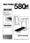
USER'S MANUAL
Model No. 831.285740
Serial No,
The serial number can be found in
the locationshown below. Write ti'ie
serial number in the space above.
Serial Number Decal
EQUIPMENT
E?e._Ji J i
:::Sm,-"iJ tram_oJ
_ mD,-'_
HF---LPLINE!
1-800-736-6879
SEARS, ROEBUCK AND CO., HOFFMAN ESTATES, IL 60179
®
210
INDEPENDENT
STEPPING
ACTION
• SPEED
LINKRESISTANCE
TABLE OF CONTENTS
WARRANTY ..............................................................................
IMPORTANT PRECAUTIONS
................................................................
BEFORE YOU BEGIN ......................................................................
ASSEMBLY
......................................................
OPERATION AND ADJUSTMENT ...........................................
CONDITIONING GUIDELINES ..........................................
MAINTENANCE AND TROUBLE-SHOOTING
.................................
"""
'..."ii
......
10
9
"..
i i.. ......
i
PART LIST ....................................................................
EXPLODED DRAWING ....................................................................
ORDERING REPLACEMENT PARTS ..................................................
J
. .....
2
3
3
4
7
10
11
Back Cover
FULL 90 DAY WARRANTY
For 90 days from the date of purchase, when proper assembly and maintenance procedures detailed in
this user's manual are followed, SEARS will, free of charge, repair or replace and install a replacement
part for any defective part, when this STEPPER is used in a normal manner.
This warranty does not apply when this STEPPER is used for commercial or rental purposes.
SERVICE IS AVAILABLE SIMPLY BY RETURNING THE STEPPER TO YOUR NEAREST SEARS
SERVICE CENTER/DEPARTMENT IN THE UNITED STATES.
This warranty gives you specific legal rights, and you may also have other dghts which vary from state
to state.
SEARS, ROEBUCK AND CO., DEPT. 817WA,
HOFFMAN ESTATES, IL 60179
l
J
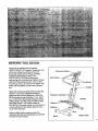
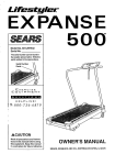
BEFORE YOU BEGIN
Thank you for selecting the innovative
LIFESTYLER" ST 210 stepper. Stepping is one
of the most effective exercises known for
increasing cardiovascular fitness, building
endurance and toning the body. The
LIFESTYLER ST 210 blends advanced
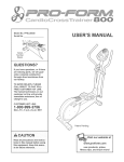
Electronic Monitor.
Watel
engineering with contemporary styling to let you
enjoy this invigorating exercise in the comfort
and privacy of your own home. Feel better, look
better and be healthier in just a few minutes a
day.
Upright
Read this manual carefully before using the
stepper. If you have additional questions,
please call our toll-free Helpline at 1-800-7366879, Monday through Saturday, 7 a.m. until 7
p.m. Central Time (excluding holidays). Before
calling, please note the product model number
and serial number. The model number is
831.285740. The serial number can be found on
a decal attached to the stepper (see the front
cover of this manual).
Before reading further, please review the
drawing at the right and familiadze yourself with
the parts that are labeled.
FRONT
Stabilizer,
BACK
RIGHT SIDE
.
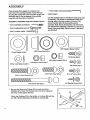
ASSEMBLY
Place all pads of the stepper in a cleared area
and remove the packing materials, except the tape
securing the sensor wire to the top of the upright (see
assembly step 6). Do not dispose of the packing
materials until assembly is completed.
• One (1) allen wrench (included)
PART CHART
Use the drawings below to identify the small pads used
in assembly. The number in paranthesis below each
drawing refers to the key number of the part. The
ASSEMBLY REQUIRES THE FOLLOWING TOOLS:
second number refers to the quantity used in
assembly. Note: Some small parts may have been
•pre-attached for shipping purposes. If a part Is not
• found In the parts bag, check to see If It has been
pre-attached.
• One (1) phillips screwdriver
• One (1) adjustable wrench
• One (1) rubber mallet
@
5/8" Cylinder Spacer (12)-2
5/8" Dome Cap (11).-2
21mm Washer (14)-2
©8
M4 Screw (30)-4
M 10 Nylon Locknut (24)-4
M8 Nylon Locknut (23)-2
20ram Lock Washer (32)-2
M5 Screw (31)-2
M 10 Plate Screw (25)-2
M10 x 1.5mm Screw (9)-2
M4 Bracket Screw (13)-2
M8 x 90mm Bolt (22)-2
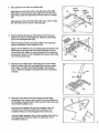
1. Be sure that there is an Endcap (15) on each end of the
Stabilizer (21). Note: The Endcaps may need to be rotated so
that they are flat against the floor.
Attach the Stabilizer (21) to the saddle on the Base (20) with the
two M8 x 90mm Bolts (22) and M8 Nylon Locknuts (23).
4
#8 x 112"Screw (3)-4
15
23
2. Apply grease to the shaft on the Base (20).
2
Apply
Grease
19
Apply grease around the hole in the right side of the Right
Pedal (18), and around the outer edge of the left side of the
Right Pedal. Slide the Right Pedal onto the shaft on the Base
(20).
Apply
Grease
Apply
Grease
Apply grease to the Left Pedal (19) in the same manner. Slide
the Left Pedal onto the shaft on the Base (20).
18
3. Peel the backing off the two Pedal Covers (17). Press one
Pedal Cover onto the Left Pedal (19). Press the other Pedal
Cover onto the Right Pedal (18).
19
18
15
Peel the backing off the two Bumpers (36). Press a Bumper
onto the underside of each Pedal (18, 19).
Attach a 21 mm Washer (14), an Endcap (15) and a 20ram Lock
Washer (32) to the right side of the Base (20) with an M10 x
1.Smm Screw (9). Attach the other Endcap (15) to the left side
in the same manner. Do not overtighten the Screws; the Pedals
(18, 19) must pivot freely.
4. Remove the four MIO Nylon Locknuts (24) from the welded
bolts in the Base (20). Set the Upright (6) on the four welded
bolts. Make sure that the Upright is angled in the direction
shown. Attach the Upright to the Base with the four M9 Nylon
Locknuts.
14
32
4
___.,_24
:..°°
24
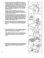
5. Remove the four M4 Screws (30) from the Left and Right
Handlebars (4, 5). Remove the two M10 Plate Screws (25) from
the Handlebar Plate (2). Back the M5 Screw (31) out of the lower
end of each Handlebar (4, 5).
30
2
Insert the Left Handlebar (4) into the Handlebar Plate (2).
Thread the two M4 Screws (30) into the left side of the
Handlebar Plate. Do not fully tighten the Screws yet.
Insert the Right Handlebar (5) into the Handlebar Plate (2). Do
not thread the M4 Screws (30) in the right side of the
Handlebar Plate yet.
5
.
Slide the lower end of the Left Handlebar (4) onto the upper
post on the Upright (6), Rotate the Right Handlebar (5) down
and slide the lower end onto the upper post on the Upright. Set
the Handlebar Plate (2) on the Upright. Insert the Sensor Wire
(10) through the indicated slot in the Handlebar Plate. Do not
let the Sensor Wire slip through the slot until assembly
step 7 is completed. Push the lower ends of the Handlebars
tight against the Upright and tighten the two M5 Screws (31)
into the Handlebars.
6
2
4
10
3%
Tighten the two M4 Screws (30) into the right side of the
Handlebar Plate (2). Tighten the Screws in both sides of the
Handlebar Plate. Attach Handlebar Plate to the Upright (6) with
the two M10 Plate Screws (25).
7.:"The Electronic Monitor (1) requires two "AA" batteries (not
_included); alkaline batteries are recommended. Slide open the
battery cover and remove the battery clip from the Monitor (see
the inset drawing). Find the markings inside the battery clip
showing which direction the batteries must be turned. Press two
batteries into the battery clip. Replace the battery clip in the
Monitor and close the battery cover.
7
Battery Clip
Win
Connect the Sensor Wire (10) to the wire extending from the
Monitor (1). Attach the Monitor to the Handlebar Plate (2) with
the four #8 x 1/2" Screws (3). Be careful not to damage the
Wires,
8; Slide a 5/8" Cylinder Spacer (12) and a Resistance Cylinder (7)
onto each of the lower posts on the Upright (6). Tap a 5/8"
•Dome Cap (11) onto the end of each post.
8
Rest the Right and Left Pedals (18, 19) on the brackets at the
lower ends of the Resistance Cylinders (7). Make sure that the
brackets are fully inserted into the same slots under both
Pedals.
Bracke
Bracket
9. Remove the two M4 Bracket Screws (13) from the Upright (6).
Attach the Water Bottle Bracket (28) to the Upright with the two
M4 Bracket Screws. Slide the Water Bottle (27) into the
Bracket.
6
9
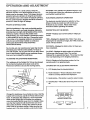
OPERATION AND ADJUSTMENT
Place the stepper on a level surface. Keep the
electronic monitor out of direct sunlight or the LCD
display may be damaged. Note: The stepper features
precision hydraulic cylinders for long life and troublefree operation; due to the nature of hydraulic cylinders,
the floor underneath the stepper should be covered to
protect it in case of slight oil leakage.
PROPER STEPPING FORM
Hold the handlebars in the most comfortable position.
Step onto the pedals and begin stepping, alternately
pressing down the right and left pedals with a smooth,
continuous motion. Because the pedals move
independently, you must maintain a continuous motion
or both pedals will sink to the floor. Change the height
of your step or the stepping resistance as necessary
until you can comfortably maintain a continuous
motion (see ADJUSTING THE STEPPING
RESISTANCE below).
As you step, you can exemise your upper leg muscles
by keeping your feet flat on the pedals. To focus on
your calf muscles, rise on your toes as you step. Stand
erect or lean forward slightly as you exercise; always
keep your back straight to avoid injury.
WARNING: The resistance cylinders become very
hot during use. Allow the resistance cylinders to
cool before touching them.
ELECTRONIC MONITOR OPERATION
The electronic monitor features a selection of five
different modes to provide you with continuous
feedback as you exercise. Please read these
instructions before operating the monitor.
DESCRIPTION OF THE MODES
SPEED--Displays your current speed, in steps per.
minute.
TIME--Displays the elapsed time. Note: If you stop
stepping for ten seconds or longer, the TIME mode will
pause until you resume.
DISTANCE-Displays
have completed.
the total number of steps you
CALORIE--Displays the total number of nutritional
Calodes you have burned. Note: The number
displayed is an approximate figure. The actual number
may vary depending on the stepping resistance.
ADJUSTING THE STEPPING RESISTANCE
The resistance of the Pedals (18, 19) can be changed
by mo_ng the brackets at the lower ends of the
Resistance Cylinders (7) (see the drawing below).
SCAN-Displays all of the above modes, for five
seconds each, in a repeating cycle.
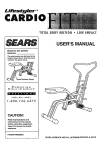
DIAGRAM OF THE ELECTRONIC MONITOR
A. LCD display (see the drawing below).
B. Mode indicators--These
indicators show which
mode is currently selected and displayed.
18
C. Mode button--This
button is used to select modes•
D. On/off button--This
eft.
button turns the power on and
A
Change the resistance of one Pedal at a time. Hold the
• bracket with one hand, and lift the Pedal with the other
hand. To decrease the resistance, move the bracket
closer to the Upright (6); to increase the resistance,
move the bracket farther away from the Upright. Make
sure that the bracket is fully inserted into one of the
slots under the Pedal. Change the resistance of the
other Pedal in the same manner. Make sure that the
brackets are in the same position under both Pedals.
B
DISTANCE
c-{-NODS
CALORIE
][
SCAN
--FD
ON/0FF
7
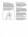
BA'I-I'ERY INSTALLATION
OPERATING THE ELECTRONIC MONITOR
The Electronic Monitor (1) requires two "AA"
batteries (not included); alkaline batteries are
recommended. Slide open the battery cover and
remove the battery clip from the Monitor (sea the inset
drawing). Find the markings inside the battery clip
showing which direction the batteries must be turned.
Press two batteries into the battery clip. Replace the
battery clip in the Monitor and close the battery cover.
.
If there is a thin piece of clear plastic on the
front of the electronic monitor, remove it before
operating the monitor. To turn on the power,
press the on/off button or simply begin stepping.
The entire display will appear for two seconds; the
monitor will then be ready for operation.
2. Select one of the five modes:
Connect the Sensor Wire (10) to the wire extending
from the Monitor (1). Attach the Monitor to the
Handlebar Plate (2) with the four #8 x 112"Screws (3).
Be careful not to damage the Wires.
SCAN mode--When the power is turned on, the
SCAN mode will be selected automatically. One
mode indicator will show that the SCAN mode has
been selected, and a second mode indicator will
show which mode is currently displayed. The SCAN
mode can also be selected by repeatedly pressing
the MODE button.
SPEED, TIME, DISTANCE or CALORIE mode-These modes can be selected by repeatedly
pressing the mode button. A mode indicator will
show which mode has been selected. The modes
are selected in the following order: SPEED, TIME,
DISTANCE, CALORIE, and SCAN.
3. To reset the modes, turn the power off and then on
again by pressing the on/off button twice.
.
Batter?
Battery Clip
To turn off the power, press the on/off button.
Note: If the stepper pedals are not moved and the
monitor buttons are not pressed for four minutes,
the power will turn off automatically.
CONDITIONING
GUIDELINES
The following guidelines will help you to plan your
exercise program. Remember that proper nutrition and
adequate rest are essential for successful results.
WHY EXERCISE?
Exercise has proven essential for good health and
general well-being. Regular participation in a wellrounded exercise program also results in a stronger
and more efficient head, improved respiratory function,
increased stamina and endurance, better weight
management and body fat control, increased ability to
deal with stress, and greater self-esteem and
confidence.
During the first few months of your exercise program,
keep your heart rate near the low end of your training
zone as you exercise.
After a few months of
regular exercise, your
heart rate can be
increased gradually until
it is near the middle of
your training zone as
you exercise. To
measure your heart
rate, stop exercising and
place two fingers on
your wrist. Take a six
second heartbeat count. Multiply the result by ten to
find your heart rate. (A six second count is used,
.
because your heart rate drops quickly when you stop
exemising.) If your heart rate is too high, decrease the
intensity of your exercise. If your heart rate is too low,
increase the intensity of your exercise.
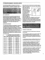
EXERCISE INTENSITY
To maximize the benefits of exercising, it is important
to exercise with the proper intensity. The proper
intensity level can be found by using your head rate
as a guide. For effective aerobic exercise, your heart
rate should be maintained at a level between 70% and
85% of your maximum heart rate as you exercise.
This is known as your training zone. You can find your
training zone in the table below. Training zones are
listed for both unconditioned and conditioned persons
according to age.
TRAINING
ZONE(BEATS/MIN.)
AGE
UNCONDITIONED
CONDITIONED
20
138-167
133-162
25
136-166
132-160
30
135-164
130-158
35
134-162
129-156
40
132-161
127-155
45
131-159
125-153
50
129-156
124-150
55
127-155
122-149
60
126-153
121-147
65
125--151
119-145
70
123-150
118-144
75
122-147
117-142
80
120-146
115-140
55
118-144
114-139
WORKOUT GUIDELINES
A well-rounded workout should include the following
three phases:
A warm-up phase, lasting 5 to 10 minutes. Begin with
slow, controlled stretches, and progress to more
rhythmic stretches to increase the body temperature,
heart rate and circulation in preparation for strenuous
exercise.
A cardiovascular phase, including 2.0-30 minutes of
exercising with your heart rate in your training zone.
A cool-down phase, consisting of 5-10 minutes of
stretching. Thorough stretching offsets muscle
contractions and other problems caused when you
stop exercising suddenly. Stretching for increased
flexibility is often most effective during this phase. This
phase should leave you relaxe_land comfortably tired.
To maintain or improve your condition, complete three
workouts each week, with at least one day of rest
between workouts. After a few months of regular
exercise, you may complete up to five workouts each
week, if desired. Whatever time you choose, be
consistent and stick with it. Remember, the key to
success is CONSISTENCY.
9
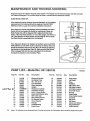
MAINTENANCE
AND TROUBLE-SHOOTING
Regularly inspect and tighten all parts of the stepper. The stepper can be cleaned using a soft cloth and mild,
non-abrasive detergent. Do not allow liquid to come in contact with the electronic monitor.
ELECTRONIC
MONITOR
if the electronic monitor displays incorrect feedback, or if the display
becomes faint, the batteries should be replaced. See BATTERY
INSTALLATION on page 8 for battery installation instructions.
If the electronic monitor still displays incorrect feedback, the Reed
Switch (10) in the Upright (6) should be repositioned. Raise the
Right Pedal (18) until the Magnet (33) is aligned with the Reed
Switch, Slide the Reed Switch in or out of the Upright until there is a
1/4" gap between the Reed Switch and the Magnet. Do not push
the Reed Switch completely Into the Upright.
If the Electronic Monitor (1) displays no feedback when the STEPS
PER MINUTE or CALORIE mode is selected, the Sensor Wire (10)
should be checked. Remove the four #8 x 112"Screw (3) attaching
the Monitor to the Handlebar Plate (2). Make sure that the Sensor
Wire is plugged fully into the wire extending from the Monitor,
Reattach the Monitor to the Handlebar Plate.
-2
PART LISTmModel
10
Key No.
Part No.
Qty.
1
2
3
4
5
6
119136
120607
013423
120612
120615
1
1
4
1
1
8
9
10
11
12
13
14
15
16
17
No. 831.285740
Description
R0795A
Key No.
Part No.
Qty.
Description
Electronic Monitor
Handlebar Plate
#8 x 112' Screw
Left Handlebar
Right Handlebar
18
19
20
21
22
125046
125045
121894
121600
013266
1
1
1
1
2
Right Pedal
Left Pedal
Base
Stabilizer
M8 x 90ram Bolt
120613
1
121996.5_(, 2
120610
2
Upright
Resistance Cylinder
Handlebar Bushing
23
24
25
012042
121050
121043
2
4
2
M8 Nylon Locknut
M10 Nylon Locknut
M10 Pl_e Screw
121518
125047
100151
121596
121047
121607
121599
2
1
2
2
2
2
4
MIO x 1.5ram Screw
Reed Switch/Sensor Wire
5/8" Dome Cap
5/8" Cylinder Spacer
M4 Bracket Screw
21mm Washer
Endcap
26
27
28
29
30
31
32
121049
121475
120757
119887
01.3222
121044
121519
2
1
1
1
4
2
2
Bumper
Water Bottle
Water Bottle Bracket
Grommet
M4 Screw
M5 Screw
20ram Lock Washer
120818
121603
4
2
Pedal Bushing
Pedal Cover
33
#
113349
123569
1
1
Magnet/Retainer
User's Manual
Note: "#" indicates a non-illustrated part. See the back cover for information about ordering replacement parts.
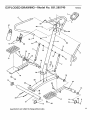
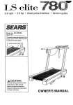
EXPLODED
DRAWING'Model
No. 831.285740
R0795A
25
17
16
"
24
31
=
16
19
I
15
26
20
II
I
18
33
16
23
21
26
Specifications are subject to change without notice.
11
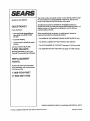
, EARS
Model No. 831.285740
QUESTIONS?
if you find that:
• you need help assembling or
operating the LIFESTYLER
ST 210:
• a part is missing
• or you need to schedule repair
service
The model number and serial number of your SEARS LIFESTYLER =
ST 210 are listed on a decal attached to the frame. See the front
cover of this manual to find the location of the decal.
All replacement parts are available for immediate purchase or
special order when you visit your nearest SEARS Service Center. To
request service or to order parts by telephone, call the toll-free
numbers listed at the left.
When requesting help or service, or ordering pads, please be
prepared to provide the following information:
• The NAME OF THE PRODUCT (SEARS LIFESTYLER <'ST 210)
• The MODEL NUMBER OF THE PRODUCT (831,285740)
• The PART NUMBER OF THE PART (see page 10 of this manual)
call our toll-free HELPLINE
1-800-736-6879
• The DESCRIPTION OF THE PART (see page 10 of this manual)
Monday-Saturday,
7 am-7 pm
Centra| Time (excluding holidays)
REPLACEMENT
PARTS
If parts become worn and need
to be replaced, call the following
toll-free number
1-800-FON-PART
(1-800-366-7278)
SEARS, ROEBUCK AND CO., HOFFMAN ESTATES, IL 60179
Part No.123569 RO795A © 1995 Sears, Roebuck and Co,
Printed in China