1
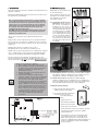
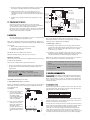
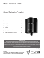
MGS – Murco Gas Sensor
Check / Calibration Procedure*
Content
Page
1- Introduction
2
2- Bump Test
2
3- Calibration
3
4- Additional recommendations
3
5- Normalisation
3
6- Sample Test Certificate for System Log
4
*Technician use only
These units must be checked / tested and /or calibrated by a suitably qualified technician who must test or calibrate the unit in accordance
with the instructions as provided or set out in the relevant manual and the standards set down in their particular industry/country.
Suitably qualified operators of the unit should be aware of the regulations and standards set down by their industry/country for the testing or
calibration of this unit. These notes are only intended as a guide and insofar as permitted by law the manufacturer accepts no responsibility
for the Calibration and Testing or operation of this unit.
Failure to test or calibrate the unit in accordance with the then applicable instructions and with industry guidelines may result in serious injury
including death and the manufacturer is not liable for any loss injury or damage arising from improper testing or calibration or inappropriate
use of the unit.
The testing or calibration of the unit must be carried out by a suitably qualified technician, in accordance with the testing or calibration manual
and in compliance with locally applicable guidelines and regulations.
10 ASH (1)
Murco Ltd.
114a Georges Street Lower, Dun Laoghaire Co Dublin. Ireland,
e-mail: [email protected] web: www.murcogasdetection.com
1
1 - I N T RO DUC T I ON
2- B UM P T E S T (e ver y year )
The frequency and nature of testing or calibration may be determined by local
regulation or standards.
Ideally bump tests are conducted on site
in a clean air atmosphere.
EN378 and the FGAS Regulation require an annual check in accordance with
the manufacturer’s recommendation.
Prior to carrying out a bump test, check
and adjust the zero setting as described
in the Calibration section page 3 Sensor PCB 1.1 and 2.2.
Murco recommends annual checks by bump test, and gas calibration
on site at two yearly intervals in the case of semiconductor SC sensors
and infrared IR sensors with sensor replacement every five years or as
required. In the case of electrochemical EC sensors we recommend
annual bump test and sensor replacement at two yearly intervals and
gas calibration. This should eliminate end of life concerns, and
constantly renew the detection system.
If the MGS is exposed to a large leak it should be tested to ensure correct
functionality by electrically resetting the zero setting and carrying out a
bump test, see procedures below.
2.1 Semiconductor and IR sensors for
hydrocarbons: We offer cylinders of
gas at known concentrations for
quantified tests. This consists of
exposing the sensor to the gas and
checking that alarm lights and relays
are activated. If this is not available,
for a non-quantified test you can use
a gas cigarette lighter. By cracking
open the valve without igniting the
gas, you release the gas onto the
sensor and force it into alarm. Check
that alarm light, sounder and relay
are activated.
There are two concepts that need to be differentiated: bump test and
calibration
Bump Test: This consists of exposing the sensor to a gas and observing its
response to the gas. The objective is to establish if the sensor is reacting to
the gas and all the sensor outputs are working correctly. There are two types
of bump test.
Calibration Kit
Flow
Regulator
Typical Flow
0.3L/Min
Outlet 5/8’’
18 UNF
(C10)
Flexible nonabsorbant
tubing
Vented
Calibration
Hood
Cylinder
360mm high x 88mm diameter
440mm high with flow regulator
110L capacity of calibration gas
Weight 1.4 kg
Quantified: where a known concentration of gas is used, or
Non-Quantified: where a gas of unknown concentration is used.
Calibration: This consists of exposing the sensor to a calibration gas, setting the
“zero” or “Standby voltage”, the span / range, and checking/adjusting all the
outputs, to ensure that they are activated at the specified gas concentration.
Procedures for bump test and calibration vary depending on the sensor
technology used and the gas in question. The MGS is available in three sensor
versions: Semiconductor (S
S C), and Electrochemical (EE C) an d in f rar ed (I R ).
Before you carry out the test or calibration:
1- Advise occupants, plant operators, and supervisors.
2- Check if the MGS is connected to external systems such
as sprinkler systems, plant shut down, external sirens
and beacons, ventilation, etc. and disconnect as
instructed by the customer.
3- Deactivate alarm delays if selected at JP5, JP6 as per
instructions in Diagram 1.
4- For Bump Test or Calibration the MGS should be
powered up overnight. If the unit has been installed and
running for about 24 hrs, and you need to power it off
for a short time to set the delay at 0 min, then the
normalisation period is about 5 min (this is indicated by
the green LED flashing) and then you can begin the
testing or calibration. If sensors have been in long-term
storage or the detectors have been turned off for a long
time, normalisation would be much slower. However
within 1-2 hours the sensor should have dropped below
the alarm setting and be operational. You can monitor
normalisation progress exactly by monitoring the
sensor output, on CON 2 between pins OV & VS.
See Section 5.
2.2 Electrochemical sensors: We offer Ampoules of ammonia (NH3) at 100ppm
and 1.000 ppm. Cylinders of calibration gas are also available. These are a
quantified test. For details of other Ampoules, please contact us.
2.3 Infrared sensor for CO2: We offer Ampoules of CO2 at 5000 ppm.
Cylinders of calibration gas are also available. These are a quantified test. If
these are not available, then you can breathe on the sensor. Human breath
has enough CO2 to trigger the alarm. This is a non-quantified test.
2.4 Bump test using gas ampoules:
1- Make sure that both the ampoules and the
calibration beaker are clean and dry.
2- Unscrew the beaker hold screw and place
the ampoule so that is sits in the
base of the beaker. As per
illustration.
Di a g r a m 1
Zero Span
SW2
P3
3- Tighten on the screw
ampoule without breaking it.
SW1
P2
Relay
+ Sounder
P1
4- Remove the enclosure lid of
the gas detector (not in Ex area).
LD2
LD1
JP6
6
5
4
3
2
1
JP1
CN1
CN2
CN3
Relay & Sounder Delay – JP5 & JP6 off : no delay
JP5 on only : 1 Minute
JP6 on only : 5 Minutes
JP5 & JP6 on : 10 Minutes
JP3 – on : 4-20mA or 2-10Volt output
off : 0-10Volt or 0-5 Volt output
JP2 – on : Sounder enabled
JP1 – on : 0-5Volt output
off : 0-10Volt output
NC
COM
NO
I
V
0V
iv
0V
A
D
2
5- Connect voltmeter to monitor sensor response, monitor 010v (Jumper JP1 and JP3 off) response on CON 2
between pins OV & V.
6- Place the beaker over the sensor head using the multi
sensor adaptor to fit the sensor, or, if an Exd, IP66 or
Remote sensor head version, screw the beaker on the
remote sensor head M42 thread, or M35 thread adaptor. It
should be as tight fitting as possible to allow maximum
exposure to the gas.
7- Tighten on the ampoule until it shatters allowing the contents to diffuse
in the beaker. It should be left in place for approximately 5 min.
Electrochemical or IR Sensor
SW2
D iagr am 3
SW1
Short to Cancel
Warm up Delay
8- Voltage output will increase. This confirms that the sensor is
responding. In the case of an ampoule quantified test a response
equivalent to at least 50% of the test gas will confirm that the system
is in order.
Sounder & Relay Set
Point Voltage (Ref 1)
Adjust Span
(Adjust zero in
IR model)
0V
Adjust Zero
(Adjust span in
IR model)
9- Carefully remove any ampoule remains from the gas detector and
beaker.
Sensor Voltage (VS)
6
5
4
3
2
1
Adjust Sounder
and Relay set point
(P1)
2 . 5 Bu m p Te st U sin g Gas C ylin d er s.
Remove the enclosure lid of the gas detector (not in an Ex area).
Connect voltmeter to monitor sensor response, monitor 0-10V (Jumper
JP1 and JP3 off) response on CON 2 between pins OV & V.
Expose the sensor to gas from the cylinder. You can place the entire MGS
into a plastic bag or use a plastic hose/hood to direct gas to the sensor
head. A response of above 80% is acceptable.
CN1
CN2
Relay and Sounder Delay – JP5 & JP6 off : no delay
JP5 on only : 1 minute
JP6 on only : 5 minutes
JP5 & JP6 on : 10 minutes
JP4 – on : Not used
JP3 – on : 4-20mA or 2-10 Volt output
off : 0-10Volt output
JP2 – on : Sounder enabled
JP1 – on : Divide Voltage output by 2
(0-5 or 1-5 Volt output
off : full 0-10 or 2-10 volt output
AC DC
CN3
A
D
Power
12 to 24V DC
12 to 24V AC
Jumper for
AC or DC
Relay Output
4-20mA output
0-5/1-5/0-10/2-10 Volt output
0V
A
D
3 - C A L I BR AT IO N
2- Electrochemical Sensor (EC)
This is the adjustment of the gas detector’s accuracy or recalibrating after
sensor element exchange using calibration gas.
There are two adjustments required: the zero and the span. They are
monitored at 0V and VS on a 0-5V scale. If the target range is 0-1000ppm,
and the gas used is 1000 ppm then 5V=1000ppm.
Murco offers a calibration kit that consists of a Calibration gas cylinder, a flow
regulation valve with flexible non-absorbant tubing and vented calibration hood.
3- Infrared (IR) (see Diagram 3)
Tools required:
1- Gas can with the appropriate gas and concentration
2- A voltmeter- crocodile clips recommended
3- Estimate 30 min per sensor
3.1- Pot VR202 is used to adjust the zero of the range (span). Monitor the
output between 0V (negative) and VS (positive) and expose the sensor to
Nitrogen or zero air, and once stable, adjust the Pot to 0 V or slightly
positive (0.01 V is acceptable).
The MGS has three sensor PCB versions: SC, EC, IR.
3.2- Pot VR201 is used to calibrate the range (span) of the sensor. Monitor
the output between 0V (negative) and VS (positive). Expose the sensor to
calibration gas and allow to stabilise and adjust pot VR202 to 5V.
Calibration and alarm relay set point is done on a 0-5V scale.
NOTE: Sensors outputs are linear, thus as long as you have a gas canister of
known concentration you can calibrate to any desired range.
Adjusting the alarm relay
This process is the same for all versions. See diagram 2 and 3 for location of pot
P1 and test points 0V and REF1.
Example: For a range of 0-1000ppm, and a canister of the target gas at
The first step to setting the alarm relay at the desired levels:
800ppm
The 0-5V signal corresponds to 0-1000, thus if using the above canister:
Voltage= 800 ppm x 5 = 4V and so the output voltage signal should
1000
be adjusted to 4V.
1- Pot P1 is used to adjust the set point at which the relay activates. Monitor
the output between test points 0V (negative) and REF1 (positive). See
example below.
Example: For a range of 0-1000ppm, relay @ 100ppm
Relay = 100 ppm x
5
so that
Alarm relay = 0.5 Volts
1000
while the 0-5V output sensor signal corresponds to 0-1000 ppm range.
4- A DD IT I ON A L R E CO M ME N DAT I ON S
FAL S E AL A RM S: If false alarms are being triggered by background gases,
paint fumes, etc, extreme humidity or temperature conditions, you will find
that the zero has moved to a + value, you can adjust the zero setting back to
zero to compensate. You may also increase the response time delay to help
eliminate false alarms.
Sensor PCB – adjusting the detection range
1- Semiconductor Sensor (SC) (see Diagram 2)
5. N o rm alisat io n P erio d
There are two adjustments required: the zero and the span. They are monitored
at 0V and VS on a 0-5V scale. If the target range is 0-1000ppm, and the gas
used is 1000 ppm then
D i a g ra m 2
5V=1000ppm.
1.1- Pot P2 is used to adjust the
zero of the range (span).
Monitor the output between
0V (negative) and VS
(positive) and adjust the Pot
to 0 V or slightly positive
(0.01 V is acceptable).
0V
REF1
Zero Span
VS
SW2
P3
Sensor Type
Electro-Chemical
Semi-Conductor
Infrared
SW1
P2
P1
Relay
+ Sounder
LD2
LD1
If sensors have been in long-term storage or the detectors have been turned
off for a long period, normalisation would be much slower. However within 12 hours sensors should have dropped below the alarm level and be
operational. You can monitor progress exactly by monitoring the 0-10V
output, when the output settles around zero the sensor is normalised. In
exceptional circumstances the process can take up to 24hours or more to get
to 0V, again monitor the 0-10V output and you can see what is happening.
JP1
CN1
CN2
Stabilised ~0V
20-30 Seconds
1-3 Minute
2 Minute
The electro-chemical sensor on power up outputs a signal voltage normally
below the set alarm level. Semiconductors output over the + max scale i.e. >
5V. Both move towards zero as they stabilise.
JP6
6
5
4
3
2
1
CN3
NC
COM
NO
I
V
0V
iv
0V
2.2- Pot P3 is used to calibrate the
range (span) of the sensor.
Monitor the output between
0V (negative) and VS
(positive). Expose the sensor
to calibration gas and allow to
stabilise and adjust pot P3 to
5V.
Below we show typical time to normalize for various sensor types. The units
are powered up and the output voltage monitored on the 0-10V-output. The
approximate time to drop to near 0V is shown.
A
D
3
MGS Test Certificate (Example)
(Download original from our web site www.murcogasdetection.com. Use in Conjunction with the Murco Check Calibration Procedure)
Pr oduc t De s c rip tion: MGS
Se r ia l Num be r: 12345
D a te of F ir s t Ca lib ra tion: (see Rating Label) 25/10/05
D a te of L as t Ca libr a tion: 25/10/05
Ty pe /R a nge of Te s t G as : Cylinder 1000ppm R404a, batch no xxxx
1.
Carry out Bump Test (Set delay to zero)
Power (Green LED)
Visual Alarm (Red LED)
Sounder Operating
Relay Operating
Remote Systems if connected to relay
C h ec k A n a l o g u e O u t p u t i n U s e , e . g .
0 – 10V
Sy s te m Pa s s e d
If system failed, carry out a gas calibration. See below.
2.
On site Gas Calibration (2 Yearly)
Sy s te m Pa s s e d
If the MGS did not respond correctly and could not be recalibrated due to age, exposure to gas etc, then either the MGS or the
sensor element should be replaced (and recalibrated) and the test process repeated.
Sy s te m Pa s s e d
We hereby certify that the above specified test procedure has been performed and the MGS is performing as specified.
Test Performed by
Signature
Date
4