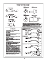
1
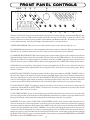
MANLEY
LABORATORIES, INC.
THE WAVE
OWNER'S MANUAL
TUBES
RULE
brought to you by the clever folks at:
MANLEY LABORATORIES, INC.
13880 MAGNOLIA AVE.
CHINO, CA. 91710 USA
TEL: (909) 627-4256
FAX: (909) 628-2482
email: [email protected]
website: www.manleylabs.com
Revision 3-23-2006 by EM
CONTENTS
SECTION
PAGE
INTRODUCTION
3
MAINS CONNECTIONS
4
CONNECTING YOUR WAVE
5, 6
THE FRONT PANEL
7, 8
THE BACK PANEL
9, 10
THE EXTERNAL POWER SUPPLY
10
THE REMOTE CONTROL
11
THE GUTS, TRIMS, SWITCHES, ETC
12
DIP SWITCHES
13
ERRATA
14
FEATURES & CREDITS
15
SPECIFICATIONS
16
TROUBLE SHOOTING
17,18
BLOCK DIAGRAM
19
APPENDIX - WIRING CABLES
20
WARRANTY
21
WARRANTY REGISTRATION
22
INTRODUCTION
THANK YOU for choosing the WAVE by MANLEY. You have possibly chosen this product because you auditioned
it in a store or heard it at a HiFi show and were impressed with the sound. It may have been the right combination
of price, power, features, and styling for you. It may have been because you know the Manley Labs reputation for
quality, reliability and integrity. If any or all of these were the reasons, you made a good choice and for that, we thank
you for all eternity.
The WAVE is a unique product combining a killer 24/96 Digital to Analog Converter with a full-featured audiophile
analog vacuum tube preamplifier. It is one of the very few products equally at home as the heart of a professional
Mastering studio facility as it is as the centerpiece of an audiophile home system. The combination of features and
functions came about from analyzing existing systems and finding them functional but lacking in elegance in signal
flow, operational convenience, and synergy. We set out to build something we wanted in our own living rooms,
something that could be upgraded as new standards evolved, and something that could be flexible to work with mixed
balanced, unbalanced, analog, and digital connections. A swiss army knife of sorts...
The initial digital board used in the first generation units, (the "First Waves" as it were) was designed around the
ULTRAANALOG 20-bit DAC modules, the AES-21 jitter reduction input module, and the Pacific Microsonics HDCD
decoder. This chipset ruled the 1990's audiophile digital world. In 2002 we commissioned an excellent 24 bit, 96KHz
DAC board design from talented designer Fred Forssell for the second generation units, in current production as of
this writing.
The WAVE accepts four digital inputs in the following formats: AES, SPDIF, TOSLINK, and ST Glass Fiber. The
four analog inputs come as stock loaded with two stereo RCA's + two stereo XLR. Other configurations can be customordered as desired. To provide extra flexibility in system integration, we have included an Insert Loop (term borrowed
from the recording studio world) perhaps more commonly referred to as a Tape Loop or Processor Loop in Audiophileland. Three outputs are provided: outputs 2 and 3 can be switched; output 1 is always on.
We packaged all this in a visually attractive box, gave it a external power supply, a full function remote control and
we didn't stop there... we hope you will also explore the WAVE's possibilities and put it to full use!
Please read over this entertaining and enjoyable owner's manual carefully as it contains information essential
to the proper operation and maximum enjoyment of this precision audio instrument.
Thank you again, and please enjoy your new WAVE! (and the clever Owner's Manual.)
UNPACKING: Unpack the unit carefully and make sure that all supplied accessories are present. Carefully examine
all items for any possibility of shipping damage. All four tubes should be standing at attention in their sockets, and
should show no signs of distress such as chipped glass, loose internal components or obvious breakage. If the
preamplifier is damaged or fails to operate, notify the shipper or your dealer or us or your local authorities immediately.
Or if you suspect The Shipping People threw it off the airplane and onto your front porch whilst flying overhead at
30,000 feet, notify the shipping company without delay and complain to them as we only guarantee this unit to be able
to survive a drop of 23,487 feet or less.
Your WAVE was packed by Manny Q. with extreme love. The sturdy box includes an assortment of protective foam
pieces, several superfluous plastic baggies, the audio chassis, the power supply, and the following components and
accessories:
a) 1 each, 6 foot IEC 3-conductor power cable appropriate for the voltage system in your country (that you will probably
replace with an expensive audiophile cord anyway.)
b) 1 each, Owner’s Manual (that we hope you will keep reading.)
c) 1 each, Remote Control with fresh batteries already installed. (We have determined that battery brand choice will not affect sonic performance.)
It is prudent to retain the shipping materials for future use, as they are custom-formed for the preamp and will
greatly minimize the chance of shipping-related damage should you ever need to put your precious WAVE in
the careless hands of The Shipping People again.
3
MAINS CONNECTIONS
Your WAVE has been factory set to the correct mains voltage for your country. (Well, that is what we
intended to do when we knew where it would be initially shipped.) The mains voltage that we built this WAVE
to operate with is typed on the serial badge, located on the rear panel of the power supply chassis. Check that
this agrees with what comes out of your wall.
There is a voltage changeover switch inside the power supply chassis! The serial number sticker badge will
proclaim the voltage we initially set the operating voltage for when the unit first shipped from the factory.
Additionally there might be a yellow 120V sticker or a red 230V sticker placed on the white fuse holder cover.
Check the sticker and the serial number voltage indication for proper mains voltage and confirm that agrees
with the voltage changeover switch setting and also agrees with what comes out of your wall. Failure to
properly comply with mains voltage requirements can cause extensive damage to the system, which of course
would not be covered by the warranty. If you relocate from, say, a 120v country to a 240v country, you will
need to switch the voltage changeover switch to agree with new new mains voltage and you will also need
replace the mains fuse value with the proper value for the new operating voltage. Or you can ignore all this
and use a step-up (or step-down) outboard converting transformer to power the unit from.
ALWAYS DISCONNECT THE IEC MAINS CABLE BEFORE OPENING THE POWER SUPPLY
AND ALWAYS ALLOW 30 MINUTES TO ALLOW THE CAPACITORS TO DISCHARGE FOR
SAFETY SAKE SO YOU DO NOT HAVE A SHOCKING EXPERIENCE.
The mains fuse may be checked by first disconnecting the IEC mains cord from the power supply’s power inlet plug. Then engage
the locking tab and gently pull out the fuseholder retainer cover. The fuse and cap should spring outward toward your fingers.
Inspect the fuse for the proper rating; change if necessary. Refer to the fuse rating chart in the specifications section of this
manual. If you do not know what a blown fuse looks like, you may measure for continuity across the fuse ends with a multimeter
set to read resistance, ohms, or the omega symbol. If your meter reads “OL” when you measure across the fuse, that means “Open
Leads” and that would mean the fuse is blown. A blown fuse usually indicates A Very Bad Thing occurred. If this has happened
to you, try to figure out why it may have happened. (Using a Fast Blow fuse when we have specified a SLO-BLO fuse is one
reason...) If you have no idea why a fuse might have just blown on its own, you might want to consult with Manley Labs or your
dealer for further advice as Something Very Bad might have occured, like the power transformer might have decided to retire
early or protest its oppressive conditions.
One way this could happen is by running the wrong mains voltage into the unit. Be sure not to do that.
If you live in a strange place...
Export units for certain markets have a moulded mains plug fitted to comply with local requirements. If your unit does not have
a plug fitted the coloured wires should be connected to the appropriate plug terminals in accordance with the following code.
GREEN/YELLOW
BLUE
BROWN
EARTH terminal
NEUTRAL terminal
LIVE terminal
As the colours of the wires in the mains lead may not correspond with the coloured marking identifying the terminals in your
plug proceed as follows:
The wire which is coloured GREEN/YELLOW must be connected to the terminal in the plug which is marked by the letter E
or by the safety earth symbol or coloured GREEN or GREEN and YELLOW.
The BLUE coloured wire must be connected to the terminal in the plug which is marked by the letter N or coloured BLACK.
The BROWN coloured wire must be connected to the terminal in the plug which is marked by the letter L or coloured RED.
DO NOT CONNECT OR SWITCH ON THE MAINS SUPPLY UNTIL ALL OTHER
CONNECTIONS HAVE BEEN MADE. (...or else...)
4
CONNECTING YOUR WAVE
Setting up the WAVE is rather easy but there is a lot of stuff to hook up...
Please refer to page 9 for a diagram of the back of the WAVE.
1. You will be connecting power last and turning the system on after all other connections are made
to prevent ugly noises as wires are connected and to prevent possible damage to your amps and
speakers. In general, it is best to make any connections with the power amps turned down or off,
the WAVE power off, and the volume control turned all the way down. Do not ever apply mains
power to the power supply without it first being attached to the main WAVE audio unit. It will not
work. DO NOT "HOT-PLUG" !
2. Before plugging in your interconnects first connect the WAVE to its external power supply. Verify
the rocker switch on the back of the External supply is in the "0" position which indicates OFF
(1=ON, 0=OFF) and that the supply has not been powered up in the last 1/2 hour (capacitors need
time to discharge). Before we go further, keep in mind the idea of an external power supply is to
keep radiated hum far from audio components so mounting the supply directly under or over the
WAVE tends to defeat the purpose. The big cable coming out of the back of the WAVE has a round
16 pin connector that mates with a matching socket on the back of the external supply. Line up the
"flats" on the plug & socket. The plug should slide in easily, and a few turns clockwise of the ring
will complete the mating and lock it securely into place.
3. On the back of the WAVE connect your power amps ( or next processor) to the WAVE Outputs.
For simple systems, use the stereo OUTPUT 1 RCA jacks which are the third set of connectors
from the left, looking at the WAVE from the back. Then start to connect all your analog line level
sources, ie; tuner, phono preamp, VCR audio outs, etc. to the four stereo analog inputs marked
ANALOG 1 through ANALOG 4. The standard issue WAVE has two pairs of RCA phono jacks
like most consumer hifi gear has and two pairs of XLR jacks typical of hi-end balanced components
and pro gear. Adapters or special cables can be used to convert XLRs to RCAs if need be. See
appendix 1 for wiring details if you need to make cables. If you plan on recording, plug your analog
Tape Deck inputs & outputs into the INSERT SEND and RETURN jacks. This allows monitored
"3rd head" recording any of the eight inputs without worrying about feedback howl. You can also
throw an external processor like an equalizer into the INSERT LOOP. SEND goes TO the extrernal
device, RETURN comes from it back into the WAVE.
4. Connect your digital sources with the appropriate interconnects to the WAVE digital inputs. There
is also a digital SPDIF output which is passed the selected DIGITAL source, before any de-jitter
or re-clocking. Note: there is a possibility of a feedback oscillation if the digital recording machine
is selected on the WAVE front panel while it is in record or the deck is in the "monitor input" or
"REC & Pause" mode. This is a situation where the digital recorder is attempting to record itself
at unity gain and oscillation is the unfortunate result. Also note: older Panasonic DAT machines
are notorious for only accepting pure consumer mode in its S/PDIF inputs and may not "see" some
sources. This is also the case if you connected directly. The AES/EBU inputs may be a better choice.
5. Before proceeding to the next step (power!) check that the On/Off switch is OFF and the volume
is turned all the way down (anti-clockwise). Now connect the IEC power cable to the back of the
WAVE's External Power Supply and then the other end to your mains wall socket.
5
STILL CONNECTING YOUR WAVE
6. Turn ON the On/Off power switch (ON=1) and then push the STANDBY button to wake up the audio chassis.
Let the WAVE warm-up for a few minutes. You should be seeing the blue LEDs light up and some more
noticably bright than others. The MUTE button should have started out bright and probably went dim after
20 seconds. This is the warm-up delay which MUTEs the outputs until the unit is warmed up and ready to
play tunes. You may push a few buttons at this point. Notice that when a button is pushed it toggles from dim
to bright to back to dim (bright = selected status). When you first turn on the WAVE it may be in a random
state. Perhaps we should start off with some buttons in the "dim" unselected mode. PHASE, INSERT and
MUTE should be deactivated and dim as soon as the 20 second warm-up/wake-up cycle is over. (If one of
the four digital sources is selected and it is not sending data, then the WAVE will automatically MUTE. Try
selecting analog Input 1 (A 1) to verify this.)
7. Let us start off checking with a favorite CD. First select the input that you have chosen for the CD. If you
are driving your WAVE with one of the CD player's Digital Outputs, press the corresponding Digital Input
select button on the WAVE. If you are coming into the WAVE via one of the stereo analog inputs, select that
input instead. Press PLAY on the CD player. If you are using one of the digital inputs, then the 44.1 LED
will be on and the WAVE MUTE will go off and the MUTE LED will be dim. Slowly turn up the Volume
Control and enjoy the music. Next check the other sources to verify they all work fine. From here on out, use
the STANDBY button to power down the WAVE when you're not listening to it to let him sleep for the night...
you no longer need to crawl around the back of the power supply and you can hide him out of the way if you
like.
Troubleshooting: It is rare that any of these initial problems occur but if they do here are some quick things to try.
More troubleshooting hints are on page 16 and 17.
SILENCE on ONE SIDE: Sometimes we don't get an interconnect pushed in enough for good contact and it
disconnects while we plug other wires in or move the component. Power down, check the interconnects, recheck all your cables. Power up and try again. If you have sound, sit back and enjoy. If not, you may want
to temporaily swap some interconnects left to right to verify that you a) have sound coming out the source,
b) each of the interconnects is verified to be working fine, c) everything IS plugged into appropriate jacks and/
or each of the Wave's inputs seems to accept signal.
HUM: First try the Grounding Posts on the back of the WAVE by un-strapping the two terminals and/or
connecting a wire from either terminal to the suspect device. You can also try a mains ground adapter if they
are legal in your country. They are also called 3 pin to 2 pin adapters or "cheaters" and are available in
hardware stores. There should be ONE GROUND in your system and only one. If two or more pieces of gear
are grounded into the wall sockets via 3 pin AC cables a ground loop can occur which will usually cause hum.
Today's power amps typically have 3 pin AC mains cables, so it is easy to see where between 2 power amps
and the WAVE, where one could have 3 grounds (at least) connected both via interconnects and AC mains
cables and that is two too many.
HISS: Usually one of the sources. This source may have a volume control that is turned down and forcing you
to turn up the volume of the WAVE to make up the gain you threw away. Adjust the source so that it is a similar
volume as your other sources. If it seems to be the one channel of the WAVE, then it is probably an input tube
(the shorter ones towards the front). Most tubes should last many years but sometimes they get noisy
prematurely. To verify, you can swap the two input tubes left to right (with the power off) then test again.
Be careful: tubes can be hot, don't bend any pins and gently wiggle the tube to remove it or insert it. Brute
force should not be needed. If it wasn't one of the input tubes then put them back into the original locations.
The output tubes will not contribute to the HISS category as they produce no gain in that stage.
NOISES: Sometimes a tube gets microphonic in shipping. This may result in a bit of "metallic ring" in the signal
or "ping" when the chassis is tapped, or even something that sounds like sputtering RF noise. Usually gently
tapping on the tube reveals the culprit and sometimes even cures it. Some amount of microphonics is to be
expected. If it is excessive, then time to replace an input tube. The output tubes will not contribute to the
NOISES category as they produce no gain in that stage.
BALANCE: The two speakers sound different. It may be the CD or source and the way it was recorded. First
try a different source. Next try swapping the inputs. Power down and swap left and right inputs. If it is the
source, then the problem will "follow" the swap. Return them to normal (L=L). You can check all the way
down the chain this way and really isolate and verify the problem. Was it the volume control on a power amp?
6
FRONT PANEL CONTROLS
PH
X 2
32K
F
S
G
1
A
2
IF
D
96K
3
T
E
T
STAN
3
2
T
MU
RT
E
OU
INS
4
T
A
S
BY
OU
WAVE
MANLEY
S
S
A
THE
TT
OO
ND
A
C
MM
48K
SP
44K
88K
O
SE
A
E
A
D
AE
ABC
BY
D
HANDCRAFTED WITH PRIDE IN CHINO, CALIFORNIA USA
REMOTE CONTROLLED ALL-TUBE PREAMPLIFIER COMBO
H
I
J
K
L
The name "The WAVE" came from a comment from our former office manager, Mickey, (now departed, RIP, bless her)
that the pattern of the blue LEDs on the faceplate looked like an ocean wave breaking. "It looks like a Wave!" She
exlaimed when she saw the first prototype that EveAnna Manley and Baltazar had made. The buttons glow dimly to
assist in darkened rooms, and only glow brightly when that function is selected and active.
A) INFRARED SENSOR: This is the reciever for the infrared remote control. It doesn't light up, ever.
B) COMMAND: Indicator to show a valid command from the remote control or front panel. Push any button and watch
him blink in sync with the transmission codes. He's letting you know that he hears your command.
C) SAMPLING RATE INDICATORS: These light up to show the incoming digital signal's sample rate and will not
light until the digital input circuitry has locked onto valid data. There are three LEDs marked 32, 44.1, & 48 and these
will light up to indicate one of those frequencies in kilohertz. If an 88.2 or 96KHz sample rate signal is present, the x2
LED will come on (same as 32KHz LED) in addition to the appropriate 88 or 96KHz LED. Simple math in action.
D) PHASE: Reverses the polarity of the Digital Converter when pushed and lit. This can be a subtle effect however
because it is performed in the digital domain does not degrade fidelity. It has no effect on any analog inputs. Really.
Promise. Trust me.
E) DIGITAL INPUT SELECT: Pushing one of these 4 buttons selects from either the AES/EBU, S/PDIF, Toslink, or
ST (glass fiber) Inputs to the Digital to Analog Converter and S/PDIF digital output. The last button pushed (of these
four) stays illuminated even if one of the four ANALOG INPUT SELECT buttons is pushed to indicate which digital
source is still feeding the digital output, presuming a valid digital signal clock is still present. This feature allows one
to use an external DAC which could return into any of the analog inputs, and allows for easy digital recording.
F) ANALOG INPUT SELECT: Pushing one of these four buttons selects that one to be the active analog input. In
conjunction with the DIGITAL INPUT SELECT, whichever the last of these eight buttons was pushed is the selected
input and that what is what you will hear.
G) VOLUME CONTROL: I guess we don't really have to explain what this does but we can tell you it is a custom-made
precision 4 gang conductive plastic motorized ALPS 50Kohm potentiometer. Two decks are used per channel because
the signal is balanced at this point before feeding the differential input of the tube line amplifier.
H) INSERT: If you know what a TAPE LOOP or PROCESSING LOOP is, then you know what this button does. It
allows an external device like a tape machine or equalizer to be used with the selected source and breaks or interrups
the normal signal flow right before the Volume Control. SEND "sends" the signal to your external destination. RETURN
"returns" the signal path back to the WAVE. "INSERT" is a word borrowed from professional audio as processors are
"inserted" into the recording path. If you not have anything plugged into the TAPE LOOP, then when the button is
pushed, the signal is going to nowhere and not coming back from anywhere, and the tunes are not continuing through
the WAVE. If this is annoying, just use a simple short pair of interconnects to patch the INSERT SENDs to the INSERT
RETURNs to defeat the INSERT button, in effect.
7
MORE FRONT PANEL CONTROLS
INSERT CONTINUED:
NOTE 1) The insert send and return can be factory wired for either balanced or unbalanced loops. Balanced Inserts use XLR
3 pin connectors appropriate for professional reel to reel tape decks and pro EQs (like the Manley Massive Passive) or other
balanced hifi gear. For a nominal charge we can also provide sensible tape monitor switching and input/output for 2 tape decks
and EQ (but we expect very few will need this level of complexity).
NOTE 2) On special request, the factory can modify the INSERT for appropriate surround sound decoders so that the INSERT
RETURN bypasses the Volume Control and Tube Line Amplifier and comes back right before the Output Select. This assumes
the surround sound decoder becomes the master volume control. This arrangement allows the high quality WAVE DAC and
selected analog inputs to feed the surround sound decoder and retains the 5.1 calibrated levels while also allowing multiple
outputs and an integrated way to quickly return to a true audiophile two channel mode. This mod is called the HT BYPASS or
Home Theater Bypass function. Contact us for more details.
I) OUTPUT 2: The WAVE has 3 final stereo outputs. Unless muted, Output 1 is always on and there are no relays in this signal
path on the output end. Output 2 and Output 3 can be turned on and off separately. The WAVE is standardly and normally set
up in an interlocked fashion so that either output 2 or 3 is on and pushing either button toggles between these two. Both cannot
be activated at the same time. This allows alternative amplifier/speaker selection. This is often needed by mastering engineers
(they typically use a few different speakers to verify quality and compatibility) and reviewers for A/B testing as well as audiophiles
with dedicated headphone systems and surround set-ups, or big speakers vs. little speakers, driving two systems from the WAVE,
but not both at the same time.
NOTE: There are internal jumpers (see page 12) that change this arrangement so that Output 2 and Output 3 can be used in
an independent fashion and both outputs can come on at the same time if you want. Pushing Output 2 will activate Output 2 and
pushing it again will turn it off. Independently, pushing Output 3 will turn it on and pushing the button again will turn it off.
An application for this is would be multiple room systems where the WAVE feeds amps and speakers in several locations at once
and you have tunes playing all over the house. If the WAVE is set to use Output 2 and Output 3 independently the remote will
only control Output 2. Output 3 can only be selected on the front panel, and not on the remote control. That's the way it is.
J) OUTPUT 3: As above. Output 3 is a transformer coupled balanced floating XLR output and is fully compatible to drive
balanced or unbalanced inputs and is the best choice when long lines need to be driven. Pin 1 (Shield/Ground) may be
disconnected in situations where ground loops and hum are be a problem.
K) MUTE: Simply silences the WAVE when activated. The WAVE has two other conditions that force MUTE. There is a 20
second time delay MUTE when the WAVE is first powered up to prevent noisy bangs and big thumps that are typical before the
tubes are drawing all their current and the output caps are charged up (it also mutes quickly on power-down to prevent more
of the same). The second "force mute" condition is when one of the digital inputs is initially selected and there is no data (or
the data is invalid). Again, this is to prevent un-controlled glitches and digital noise that you probably do not want to hear.
L) STANDBY: This is a "barely on" "sleep" mode that turns off the power to the DAC, relays, LEDs & tubes and just uses a
trickle of power to allow the front panel logic to remember its settings, respond to buttons and to the remote control. The Standby
indicator should be dim and all other LEDs will be fully off when in STANDBY mode. When STANDBY is pushed again, all
the LEDs return to the last used setting, except the MUTE which is in "force mute" for 20 seconds as the tubes warm up.
NOTE: There may be a short learning curve involved between the various combinations of MUTE, OUTPUT 2 & 3, INSERT
and INPUT SELECT where it seems annoying that you have to push buttons to get music. If you are like us, the cause is a bit
of impatience while waiting for the warm-up mute delay to disengage and pushing buttons which end up re-routing the signal
where you don't expect it to go and causing confusion when it was only muted during the warm-up. If you wait the 20 seconds
before pushing any buttons, the WAVE will return to the last used setting, where it was, before it was put in Standby.
When the WAVE is unplugged or the power turned off at the external power supply at the IEC power cord, the settings are lost
and it tends to power up with the PHASE, MUTE and OUT 3 selected but with no source selected. There is no default initial
setting so this may be random (including INSERT). You will probably need to push the PHASE, MUTE and select one of the
eight INPUTs. Depending on your system OUT 2 may have to be toggled as well. The settings are not retained with a battery,
and the logic is discrete rather than employing a micro-controller to prevent another source of clocked logic noise entering the
system. You just have to look at what is lit after you first turn it on, but using STANDBY will be painless if you have 20 seconds
worth of patience.
Very rarely the digital input reciever may lock-up when switching between various sources. Switching to a different digital input
and back usually cures this and STANDBY totally resets the DAC board.
8
REAR PANEL JACKS
LEFT
The WAVE
by MANLEY
DAC / Preamp
SERIAL NUMBER
AN EVEANNA MANLEY PRODUCTION
LINE STAGE DESIGNED BY C. HUTCHISON
PCB'S & CHASSIS BY B. HERNANDEZ
LOGIC DESIGNED BY J. GARSZVA
RIGHT
MANLEY LABORATORIES
13880 MAGNOLIA AVE., CHINO, CA 91710
PHONE (909) 627-4256 FAX (909) 628-2482
email: [email protected]
DIGITAL I/0
OUTPUT 3
OUTPUT 2
BALANCED
OUTPUT 1
UNSWITCHED
INSERT
RETURN
INSERT
SEND
ANALOG 2
ANALOG 1
GROUND
CIRCUIT
CAUTION - RISK OF ELECTRIC
SHOCK. DO NOT OPEN.
REFER SERVICING TO QUALIFIED
PERSONNEL ONLY
TO REDUCE THE RISK OF
ELECTRIC SHOCK DO NOT EXPOSE
THIS EQUIPMENT TO RAIN OR
MOISTURE
O
ANALOG 3
XLR INPUTS AND OUTPUTS
PIN 1 = SHIELD = GROUND
PIN 2 = HOT = POSITIVE PHASE
PIN 3 = LOW = NEGATIVE PHASE
POWER SUPPLY
P
ANALOG 4
N ML
K
J
I
CHASSIS
H
G F
SELECTED
DIGITAL
OUTPUT
E
ST
D
TOSLINK
C
S/PDIF
B
AES / EBU
A
NOTE: This panel shows the WAVE as it standardly ships. However, Manley Labs does custom configure individual units to
order with alternative connectors and different variations of balanced and unbalanced inputs and outputs, but we don't write
custom owner's manuals for them. This drawing may not accurately depict your exact jacks, if you had us do something custom
for you, but you should get the gist of it from this drawing.
A) AES/EBU DIGITAL INPUT: Connect the appropriate balanced digital input here. The digital interconnect should be a
proper digital AES XLR cable optimised for 110 ohm termination.
B) S/PDIF DIGITAL INPUT: As above, but the consumer version, unbalanced 75 ohm on an RCA jack. Very popular but this
interface is designed for shorter cables. Both the AES/EBU and S/PDIF are transformer coupled inputs.
C) TOSLINK DIGITAL INPUT: Another popular standard interconnect that uses a square plastic optical fiber jack.
Unfortunately it is best avoided for sonic reasons unless no other option exists.
D) ST-GLASS DIGITAL INPUT: Generally the best choice as it uses a premium glass fiber that provides the widest bandwidth,
fastest square waves, and best electrical isolation. Unfortunately, many players do not include this due to cost reasons. This
standard was created by AT&T and adopted for digital audio. These small bayonette style connectors require a quarter turn
clockwise to lock. The cable and connector can be fragile so please treat him gently when connecting or disconnecting cables
or moving the unit.
E) SELECTED DIGITAL OUTPUT: This S/PDIF output follows the last selected digital input (even if one of the analog Inputs
has been selected). This allows for digital to digital recording. The front panel LEDs indicate the last selected digital source.
Older Panasonic DAT machines may or may not be capable of dealing with this output, in our experience, but who else besides
us has those nowadays anyway? Oh well.
F) ANALOG 1 INPUT: The standard WAVE provides two stereo unbalanced RCA LINE LEVEL inputs (compatable with most
hi-fi and consumer equipment) and two balanced XLR stereo LINE LEVEL inputs (compatable with some premium audiophile
equipment and pro gear). These are not phono inputs (which require way more gain, different impedances, and the RIAA
equalization curves). You can plug line level outputs from a phono preamplifier, AM/FM receiver, tape deck, iPod line or
headphone outputs or VCR audio outputs, etc. into any of these analog line linputs (or ANALOG 2, 3 or 4). This Analog 1 input
is selected with the A 1 button.
G) GROUND TERMINALS: These ground posts are intended to help in some installations particularly where a special audio
grounding scheme is used. The top black mini-binding post is the audio circuit ground and the bottom green mini binding post
is the chassis ground. We ship these already connected together with a piece of buss wire running between them. Have a look.
Note: the AC mains "third pin" ground is tied to the power supply chassis which is consequently tied to the WAVE audio chassis.
For almost all applications these green and black ground posts should remain connected together and in most cases, you should
leave that connecting wire right where it is. If you are getting hums and buzzes, you can start experimenting with lifting the
circuit-to-chassis link and re-grounding these grounds to other parts of your system.
J) ANALOG 2 INPUT: Just like ANALOG 1 but corresponds to the A 2 input select button. No surprises here....
I) ANALOG 3 INPUT: Just like ANALOG 1 except typically built as balanced XLR connector corresponding to the A3 input
select button on the faceplate. Pinout will be Pin 1: Ground, Pin 2 (+), Pin 3 (-) for the XLR's.
J) ANALOG 4 INPUT: Just like ANALOG 3 but use the A4 button to select this guy.
9
MORE REAR PANEL JACKS
K) INSERT SEND: This is an analog output before the volume control designed to feed (SEND signal to) tape recorders or
external processors, such as an equalizer, for instance. The WAVE is standardly configured with unbalanced RCA jacks for the
INSERT SEND and RETURN, right on bottom, left on top. This SEND output is always on, even if INSERT is not selected.
The active selected input of your eight inputs will also appear here as an analog signal. Remember your WAVE has 4 x Digital
plus 4 x Analog stereo inputs making for 8 stereo inputs total.
L) INSERT RETURN: This analog input is selected when the INSERT button is lit and then is sent to the Volume Control.
It allows monitoring or A/B comparison/verification from the 3rd head monitor output from a tape deck as you record, for
example. You can also patch in the output from an Equalizer or external processor here. Or if you are dying for one more analog
input from some other source component, you can throw it in here too as you would into A1, A2, A3, or A4, and use INSERT
button to select this one. If you have no use for the INSERT SEND and RETURN jacks, we suggest that you use a short
interconnect between INSERT SEND & INSERT RETURN so that if somebody accidently pushes the INSERT button the tunes
won't escape out to nowhere and you'll be less confused...
HT BYPASS Option: We can modify the INSERT feature for easier integration of the stereo WAVE into a surround sound
system so that the INSERT RETURN bypasses the Volume Control and the WAVE's tube preamplifier stage and comes back
right before the Output Select, then you can feed a stereo output pair directly to a surround processor, for example. This allows
an external surround processor preamp to become the master volume control as the source was passed to it with no additional
volume reduction or gain. This arrangement allows any of the WAVE's eight stereo source inputs to feed two channels of the
surround sound setup retaining the 5.1 calibrated levels of the surround system while providing an integrated way to quickly
return to a true audiophile two channel mode.
BALANCED INSERT Option: Fully Balanced XLR Insert SEND and RETURN is also available upon special request.
M) Power Cable: The power cable is a captive design to minimise unnecessary touch-contact connections in favor of higher
integrity soldered ones. The cord is direct wired inside the audio unit. The other end MUST be connected to the EXTERNAL
POWER SUPPLY. We strongly advise to connect this cable first before connecting the AC mains cable at the SUPPLY. Once
all the audio connections are complete, you can then turn on the power. DO NOT HOT-PLUG!!!
N) OUTPUT 1: This is the normal RCA stereo output intended to be connected to your main amplifiers. All three outputs are
automatically muted while the WAVE's tubes warm up during the power-up cycle or if the MUTE button is engaged. As long
as the WAVE is not in MUTE mode, OUTPUT 1 is always on.
O) OUTPUT 2: Normally shipped as unbalanced RCA jacks. OUT 2 and OUT 3 are intended for alternate amplifier/speaker
combinations. You might have output 2 driving your stereo amp and speakers and switch to output 3 drives your headphone
amplifier, for instance.
P) OUTPUT 3: Like OUTPUT 2 except this stereo output is normally configured on a pair of XLR's and the signal is transformer
balanced and floating. Pinout is Pin 1: Ground; Pin 2: POSITIVE (+); Pin 3: NEGATIVE (-). It can be used to feed balanced
or unbalanced inputs on amps and is particularly useful if ground loops and hum is a problem or long lines need to be driven.
Pin 1 is ground which can be cut for a true isolated output which tends to cure some ground loops. If feeding an unbalanced device
with this output, you may GROUND Pin 3, but do not float it. Both legs of the trannie must be connected to something.
REMEMBER: You can choose whether Output 2 & 3 work independently or whether they work interlocked. See page 8 and
page 12 for more info on this and how to set the internal jumpers.
EXTERNAL POWER SUPPLY
A) FUSE: Requires a 1.5 AMP, 250V, 1/4" x 1 1/2" SLOBLO (MDL or MDA type) fuse for 100-120V operation or
0.75AMP for 220-240 Volt countries. Do NOT use FAST
BLOW fuses, only time-delay ones.
B) POWER SWITCH: 0=OFF, 1=ON. The LED on the
front indicates AC power is being fed to the power supply
and remains illuminated while in STANDBY.
C) IEC POWER CONNECTOR: The AC mains power
cable gets plugged in here. There is a voltage change-over
switch in the power supply that is set by the factory for the
mains voltage in your country. The voltage we set it for is
typed on the serial number badge.
10
10
ABC
D
D) MULTI-PIN POWER CONNECTOR: This 16 pin
connector supplies all the needed voltage rails to the WAVE
audio chassis. The WAVE also sends a signal back to the
supply to tell it whether it should rest and sleep in STANDBY
mode or come awake and do all of its job providing all the
voltages to run the whole dang shebang.
AES
A 1
Y
A
B
OP
ST
ND
M
TOS
A 3
ST
A 4
SER
THE WAVE
BY
T
P DIF A 2
UTE
IN
If the remote's command LED fails to
light when you push a button and the
WAVE is ignoring the remote's
commands, then the remote's batteries
are probably dead. Get your phillips
screwdriver out and remove the two
screws on the remote back where it
shows you to, slide the cover down, and
you'll see 3 x AA 1.5 volt dead batteries
to change. The circuit is designed to
maximise battery life while providing
enough optical power to control the
WAVE from a good distance. Batteries
will typically last a few years.
I
N
P
U
T
S
HAS
S
You will see an LED on the remote blink
whenever you push any of the buttons
and the COMMAND LED on the WAVE
front panel will indicate that it has
received the command. These are just
"confidence" or "verification" indicators.
You can also watch the WAVE simply
respond to your commands as every
function does show its status on the
front panel.
P
The Remote Control provides essentially
all the buttons found on the WAVE front
panel plus 2 buttons for Volume control.
The WAVE front panel has a big knob
for volume and a motor to control it. The
remote uses two buttons to tell the motor
to slowly and smoothly turn to increase
or decrease the volume.
E
THE REMOTE CONTROL
V
O
L
U
M
E
There is a secret way to disable all the
WAVE's faceplate buttons and make
the Remote the "only" control if for
example you don't want your kids to
"play" with the system. To do this, find a
place to hide your remote control out of
reach and then read the next page about
how to set the internal jumpers to deactivate the WAVE's faceplate buttons.
Changing any of the DIP switches in the
REMOTE will have the opposite effect.
Changing all 3 sets of DIPS is helpful
when you seem to have two remotes
that clash. See page 12 for more info.
All of the Remote Control buttons are
labelled the same and operate the same
as indicated on the WAVE's front panel.
The only possible exception is when you
reset the special jumper setting that
changes the function of the OP2/OP3
buttons from interlocked to alternating
setup as explained on Page 8 and in this
case, the remote will only be able to turn
on and off OP2. This is only the case if
the jumpers are changed, and normally
the remote is sent out with the button
labels indicating exactly what the buttons
really do.
A Few Notes: There are a few things which don't really fit anywhere else in the manual...
There is no "DeEmphasis" feature in the WAVE DAC. So few CDs ever used that Emphasis encoding anyway. It was
a lame attempt to improve the already excellent signal to noise ratio of CDs, way back in the day. If you have a few
old CDs that sound a little too bright, they might have been mastered using the Emphasis high frequency boost. Our
advice is to just replace those one or two CDs you might have with newer mastered copies that don't use that antique
DeEmphasis technique.
There is no HDCD decoding in this unit. It just was not feasible with this particular chipset. Oh well. Shoot me.
There is also no analog Phase Reverse function to flip the phase on one channel nor is there an analog polarity switch.
You can flip your speaker cables to play with phase and polarity issues. There is no MONO button. There is no DIM
button nor is there indvidual muting of each channel. For Mastering engineers and possibly a few audiophiles who
require these features we could add them using good ol' manual toggle switches on the faceplate if you want to give
up some channel separation at high frequencies. We won't be able to get those features onto the remote though. We
have a maximum of 15 buttons on the remote and it is not an easy undertaking to try to modify a 4 layer PC board.
There are no high voltages on the multi-pin connector until it is mated and the supply is told to turn on. This makes
it particularly safe. However, if it has been on, the mate disconnected and the capacitors have not yet discharged (it
takes about 5 minutes to discharge while it is connected and 15 minutes if it is disconnected) then if somebody were
to touch those pins, especially with a moist hand, they might get a 300VDC shock - non lethal, but very startling and
possibly giving pin-prick burns. Not something for children to play with. That said, the electrical AC sockets found all
over your house are far more dangerous. Poking wires, pins etc through the cooling slots is also a bad idea with any
electrical or electronic gear. Common sense stuff....
11
INTERNAL ADJUSTMENTS
INPUT
SELECTION
DIGITAL to
ANALOG
CONVERTER
PASSIVE
ANTIALIAS
FILTERS
OUTPUT
SELECTION
(& MUTE)
INSERT
7044
7044
MASTER
REGULATORS
& WARM-UP
DELAY
LEFT GAIN
TRIM
SW-016
1
2
3
12AX7
MASTER
12AX7
1
2
1
2
3
HIFI
HIFI
LEFT
JUMPER SETTING FOR
AMPLIFIER GAIN
2,3=FACTORY SET
1,2=+18DBM(MASTER)
NO JUMPER=+24BDM
(PROFESSIONAL)
RIGHT
3 4
SW-015
P-04,P-05
RIGHT GAIN
TRIM
P-06
The gain of the Wave's tube stages are set at the factory. There are only 4 trimmers (2 per
channel) but because the input to the line amplifier is balanced and it is a minimum feedback design,
it requires a trimmer for each phase or leg. So both trimmers affect the gain and the "balance" of the
two trimmers affect common mode rejection. Yes, this could have been made more convenient, but
it would have compromised some sonic performance.
The method to adjust these requires an oscillator, AC voltmeter, CD test disk with 1K digital
full scale and a special banana to XLR M cable that allows the oscillator to send between: a) pin 1 &
pin 2, b) pin 1 & pin 3, c) pin 2 & pin 3 (normal balanced) and d) between pin1 & pin2+pin3 (for
CMRR). These tests are done with the Volume control turned up full, the appropriate input selected
(nothing else) and no amplifiers connected and the Wave well warmed up.
It is not difficult but be careful - high voltages are right around the tubes. Use an insulated
screwdriver, keep one hand in your pocket and don't touch the screwdriver to any other parts.
With the oscillator set to 1 kHz and 1 volt AC RMS and the AC voltmeter meter reading Output A of
the same channel and the special cable hooked up for:
test a) the output should read 1.3 volts. If not adjust trimmer 1
test b) the output should read 1.3 volts. If not adjust trimmer 2
Repeat this several times due to interaction between the trims.
test c) should now read 4.5 volts. If not, make sure you did a) and b) correctly.
test d) should read 0.0 volts and common mode cancellation should occur.
You may have to slightly & carefully tweak either trimmer 1 or 2 to provide the deepest cancellation
and you should either switch the meter to the most sensitive scale or adjust this while listening to the
output and trimming for the lowest possible signal. If you attempt to do this listening to the output,
be careful, slow and don't change any cables until you turn off the amps. A sudden change from a
tiny signal to full tilt 1K oscillator can easily blow a speaker.
Amps are off, back to using the AC voltmeter? Good, insert the test CD, select that digital input and
the 1K full scale track. You should read 2 volts now.
12
dip switches
REAR VIEW
BACK OF FRONT PANEL
1
2
3
P-06 BLACK
*See notes below
SW-015
P-04,P-05,P-06
"FACTORY DEFAULT"
OUT 2,OUT 3 ALTERNATE
1
2
DIP SWITCHES
DEFAULT MODE
3
P-04 RED
P-05 BLUE
1
2
SW-016
3
"DRAWING NOT TO SCALE"
1
2
3
P-06 BLACK
P-04,P-05,P-06
OUT 2, OUT 3
INDIVIDUALLY
CONTROLLED
SW-015
1
2
DIP SWITCHES
DEFAULT MODE
3
P-04 RED
P-05 BLUE
1
2
SW-016
3
Jumpers marked P-04, P-05, P-06 are used to change from the default mode where OUT 2 and OUT
3 alternate interlocked or are individually (push on, push off) controlled. To set OUT 2 and OUT 3
to individually (push on, push off) mode refer to drawing for jumper configuration.
There are 3 sets of 8way dip switches, 2 on the Wave logic board marked SW-015 and SW-016 and
one in the remote. All 3 sets must be set identically for proper operation. These are used to set the
"address" function of the remote control, IR receiver and front panel. They should only be changed
in the unlikely scenario where one of your other remote controls and the Wave clash. They allow the
Wave to use a different remote control "address". All 3 should be set the same unless for some
reason you want the front panel buttons disabled. In that case, change SW-015 to be unique.
13
ERRATA
The WAVE's DAC uses Burr-Brown PCM1704 D-A converters operating at 96 KHz at all times. All inputs below
96 KHz are upsampled to 96 KHz before conversion. The upsampled output is clocked out via a Low Phase Noise/
Low Jitter precision crystal oscillator to eliminate any interface jitter or timing problems with the incoming datastream.
Multiple power supplies are used, with additional regulation and filtering located near critical components.
Differential Passive LC filtering is used on the voltage output of the DAC PCB. High Speed JFET Current to Voltage
Conversion with differential output is used to drive the Passive LC Filter before the DAC output joins up with the
analog input select buss.
Analog switching is accomplished with gold contact sealed relays. Left and right relays are well separated and single
relays switch both halves of a balanced signal. Virtually all of the logic involved for the front panel buttons and LEDS
is taken care of on the front panel board which uses standard TTL logic (no clock) for all functions. The only oscillator
involved is enabled only while a button is pushed. In STANDBY mode one small power transformer keeps the logic
circuitry alive while the big power transformer (which runs all of the other power supply rails) is disconnected from
the AC mains power. The pushbutton switches are super reliable made by EAO. The Volume Control is a custom-made
4 deck precision conductive plastic motor driven 50K attenuator made by ALPS. Left/right tracking is exceptional.
We use an ultra-low capacitance, well-shielded, balanced silver-core wire provided to us by Synergistic Research for
point-to-point audio connections.
The first stage of the line amp acts to cancel noise and distortion through high common mode rejection. The input to
this line amp is arranged to accept both balanced or unbalanced signals. The output stage is our tried and true fave,
the direct-coupled White Follower. We expect most folks to get five to ten years tube life from the factory supplied
tubes. Sometimes this is optimistic. If replacing one or all tubes do not attempt to use any but the same type tube as
removed. The 7044 or 5687 output tube has an unusual pin-out and most other tubes will not work here without cutting
up the board to swap some pins. We select the 12AX7 input tubes for best fidelity, lowest noise and low microphonics.
Picky selection is critical due to the fact that the volume control is ahead of the tube line amplifiers and it will not
attenuate any tube "issues". Any problems such as excessive hiss or microphonics will be hanging out there all the time.
This is why good tube selection is important. Manley Labs always has good tested tubes in stock if needed. If you need
spare tubes you can order them from us and we will select them for best performance in a WAVE.
OUTPUT 1 receives its signal directly from the plate-cathode White Follower output junction through an expensive
MultiCap made by RelCap. On its way to OUTPUT 3, the signal passes through a custom 1:1 Manley transformer,
the 9811, made right here at the Manley Labs factory. The 9811 has a special tertiary feedback winding that goes back
to the front end of the tube preamp stage. In the professional world where balanced lines are standard, transformers
are acknowledged as the absolute best (and most expensive) technique. Not only does a transformer provide a true
balanced output, but it can also be "floating" which isolates grounds between equipment if needed. However, adding
a transformer will impart something to the sound, however benign that might be.
The external power supply utilizes overkill ripple 'pi' filtering for the B+ voltage supplies with each channel filtered
separately. The tube heaters are DC regulated to 12 volts. The Logic and LED 5V rail is regulated in two stages: first
to 12V in the supply and then to several individual 5V points for the DACs, panel, relays, and LEDs. There are also
plus and minus 15 volt regulators for the DAC (plus the Insert Send and Return balanced to unbalanced converter ICs).
The power supply depends on a return signal from the WAVE audio chassis in order to operate and so thus it should
not be tested in isolation. The multi-pin connector has 4 extra-heavy duty pins for the filament and logic power and
12 heavy duty pins for the remaining power systems. The supply cable is a combination of 16 wires in 14 and 20 guage.
The plastic connector shell rattles less than the alternative metal version.
The WAVE uses a .375" thick anodised billet aluminum panel mounted to a steel chassis. There are removable panels
on the chassis bottom for easy access during servicing and ventilation slots in the front, bottom and top of the chassis
to keep everything cool to extend life of the components, especially the power supply electrolytic capacitors. Heat is
the ultimate enemy for those puppies! All connectors are gold plated including the power supply to provide minimal
oxidation resulting in highest integrity connections and long reliable life.
14
FEATURES & CREDITS
FEATURES:
24-Bit 96KHz Digital to Analog Converter Board
DIGITAL PHASE / POLARITY SWITCH
4 x switchable digital inputs AES, SPDIF, ST Glass, Toslink
1 x SPDIF digital output pass-through
4 x Stereo ANALOG INPUTS: (standard: 2 x stereo unbalanced RCA, 2 x stereo balanced XLR)
INSERT SEND and RETURN (Tape processor loop) Available balanced XLR or Unbalanced RCA
Motorized ALPS quad-attenuator volume control
Vacuum tube output stage (2 x 12AX7EH input tubes; 2 x 7044 JAN NOS USA output tubes)
3 x Stereo ANALOG OUTPUTS: (standard: 2 x stereo unbalanced RCA, 1 x balanced XLR)
(Output 1 is always on.)
Reference level to digital full scale: With digital -14 (CD consumer setting);
With digital -20 (Pro Studio Reference Setting)
Remote Control operates the whole faceplate
MANUAL MUTE, WARM-UP MUTE & STANDBY MODES
Separate outboard Power Supply Unit
"Manley Blue" anodized 3/8" thick by 19" rackable front panel, 17 BLUE LEDS
MANY CUSTOM OPTIONS AVAILABLE INCLUDING:
Any combinations of balanced and unbalanced I/O, or any combination of digital input types.
(Expect extra NRE charges for anything involving custom silk-screening of faceplate)
INSERT MOD FOR SURROUND PROCESSORS (RETURN POST LINE AMP)
CREDITS:
An EveAnna Manley Production. The WAVE was EveAnna's concept and most of the cosmetic look and
list of functions and feature set came from her conceptual design. It had to be good enough for her living
room too. (It is).
Baltazar Hernandez is Manley's Chief Draftsman and he spent the most time on this project on the CAD
programs laying out circuit boards, panels and boxes. He built the first few prototypes by hand as well.
Craig 'Hutch' Hutchison is Manley's Chief Designer and the new balanced line stage is from his bench as
well as the myriad of options and configuration possibilities. Hutch and EveAnna wrote this silly Owner's
Manual with some English-as Second-Language contributions from Humberto Rodriguez in our QC
department.
Jerry Garszva designed the logic involved in the front panel and remote control. You can also see his name
on any copy of Steely Dan's Gaucho and Fagen's Nightfly for which he received a few Grammys.
Bascom King & Fred Forsell are behind the 24/96 digital board.
And many other good folks contributed in listenening tests and suggestions.
Our thanks to all of these unsung heros!
15
MORE SPECIFICATIONS
POWER:
Outboard Power Supply is factory set for 100V, 120V or 220-240VAC operation
for original destination country's mains voltage.
Operating Mains Voltage: 120 to 240VAC operation changeable with power transformer re-wiring via
internal switch and fuse value change.
100VAC operation changeover achieved via rewiring of power transformer PCB.
Mains Voltage Frequency: 50~ 60Hz
Mains Fuse Value: 1.5A SLO-BLO for 100 or 120V operation
Mains Fuse Value: 0.75A SLO-BLO for 220V to 240V operation
Do not use FAST BLOW fuses.
Power consumption: 0.8A @ 120V = 96 watts
PHYSICAL:
Dimensions: 19" W x 5.25" H x 13" D
Unit Weight: WAVE = 23 lbs.; PSU = 15 lbs.
Shipping Weight: 49 lbs.
ANALOG SECTION:
INPUT SENSITIVITY: 494mV (-3.9dBu) yields 1V out
INPUT IMPEDANCE: 50Kohms
MAXIMUM INPUT LEVEL: 9.75Vrms produces 19.86V on output at 1KHz before clipping
+22dBu produces +28.18dBu on output at 1KHz before clipping
MAXIMUM GAIN: 12 dB
MAXIMUM OUTPUT: +30 dBu, 25 V rms (70V P-P) (+31dbu @ 1.5% THD)
+8.25 dBu digital full scale (2.0 V Rms)
FREQUENCY RESPONSE: 20 Hz to 20 kHz +/- .5 dB
8 Hz to 45 kHz +/- 3 dB
THD+N: 0.015% 20Hz - 20KHz bandwidth
NOISE FLOOR -88 db (20 Hz - 20 kHz) (-90 A-Weight)
S/N 120 dB analog (96 db digital)
L/R Volume Control Matching .2 dB (from -50 to max)
REMOTE CONTROL RANGE MEASUREMENTS:
Measurements done with new set of batteries.
If the remote is closer than 9 feet, the maximum angle response is around
60 to 75 degrees which is the counter sink angle of the receiver's hole in the front panel.
Distance of 9-10 ft, the maximum angle is 65-75 degrees.
Distance of 12 ft, the maximum angle is 60 degrees.
Distance of 13 ft, the maximum angle is 45-55 degrees.
Distance of 16 ft, the maximum angle is 45 degrees.
Distance of 20 ft, the maximum angle is 25-35 degrees.
Distance of 25-27 ft, the maximum angle is 0-15 degrees.
This is the maximum distance-angle the remote will do.
16
TROUBLESHOOTING
Sing along with us: "Problems, problems, problems all day long....."
NO POWER, NO INDICATORS, NADA - Does the power supply LED come on and is the Standby LED dim? If so, the unit
is in standby mode. Push that STANDBY button to make him come alive. If all lights are dark, even the LED on the PSU, probably
there's an issue with AC power. Is it plugged in? Check the fuse on the back panel. A blown fuse often looks blackened inside
or the little wire inside looks broken or its resistance measures higher than 2 ohms. A very blackened fuse is a big hint that a
Vary Bad Thing occured. Try replacing the fuse with a good one of the same value, size, and SLO-BLO type. If it blows too, then
prepare to send the unit back to the dealer or factory for repair. The fuse is a protection device and it should blow if there is a
problem. If the unit works with a new fuse, fine, it works. Sometimes fuses just blow for unknown reasons.
LIGHTS BUT NO SOUND - Lights are on but nobody's home. Probably got one too many lights. How about that INSERT
button? If that is on, and nothing connected or what is connected is off, then no music will get through. De-selecting INSERT
button should "cure" that and a reasonable solution would be to just connect a short interconnect between the Insert Sends and
Returns so that accident won't be quite as annoying next time. Is that MUTE indicator lit? Maybe there isn't a valid digital input
where you've selected. Sometimes the digital reciever locks up and de-selecting/re-selecting solves the glitch and occasionally
you might need to try Standby again to reset the DAC board - just like a computer. Don't forget about that 20 second warm-up
delay where the MUTE will be automatic. Last but not least is the Output selection if you are using Output 2 and/or Output 3.
That can certainly kill the signal too if its in the wrong state. So check all your selections.
Next try plugging the input and output cables into each other or some other piece of gear to verify that your wires are OK. If not
fix them or replace them. Assuming that cables passed sound - it probably is still a wiring thing. The Output 3 XLRs are
transformer balanced outputs which require both PIN 2 and PIN 3 to be connected somewhere. When driving an unbalanced
input PIN 3 needs to be grounded or connected to PIN 1. Same with the unbalanced RCA phono jacks - if driving a balanced
input you can't ignore the negative side (pin3). It needs to be connected to the sleeve of the RCA jack. Another way to do basically
the same thing is join PIN 1 and PIN 3 on the XLR male at the destination. Easiest way - Use the balanced Output 3 on the WAVE
and use a normal balanced cable to drive that balanced input.
LEVELS SEEM TO BE WRONG, NO BOTTOM - Several possible scenarios. Pro gear uses the nominal standard of +4 dBm
= Zero VU = 1.228 volts AC RMS. A lot of consumer gear uses a reference of -10 dBm = Zero VU. This is a 14 dB difference
that will certainly look goofy and may tend to distort. Often there are switches on the semi-pro gear to choose the pro reference
level. There is the GAIN setting jumper on the tube board to look at. If the loss looks close to 6 dB and it sounds thin then one
half of the balanced signal is lost (one leg not connected). The cause is probably wiring again. One of the two signal carrying
wires (the third is ground / shield on pin 1) is not happening. Check the cables carefully because occasionally a cable gets modified
to work with a certain unit and it seems to work but its wrong in other situations. If only one side of the WAVE exhibits this
problem, it may be a problem in the WAVE. See the next item. Of note: the INSERT output is not standardly calibrated in
reference to digital inputs and is simply the level that the DAC board outputs. We chose to use less electronics here to keep the
path as pristene as possible for the audiophile needs and the main gain of the unit is made up in the vacuum tube stage.
ONE SIDE WORKS FINE BUT THE OTHER SIDE IS DEAD - Let's assume this is not wiring. We are pretty sure it is the
WAVE. If it were solid state you would generally send it back for repair. Being a tube unit, you can probably find the problem
and fix it yourself in a few minutes. Not too many years ago, even your parents could "fix" their own stuff by taking a bag of tubes
down to the corner drug store and checking the tubes on a tube tester - but these testers are hard to find today. A visual inspection
can usually spot a bad tube just as well. Be careful - there are some high voltages inside the chassis and tubes can get pretty warm,
but if you can replace a light bulb you should be able to cruise through this. Before you remove a tube, just take a look at them
powered up. They should glow a bit and they should be warm. If one is not, you have already found the problem. The tube's
filament (heater) is burnt out or broken like a dead light bulb. The other big visual symptom is a tube that has turned milky white
- that indicates air has gotten into the tube or we've joked "the vacuum leaked out". Either way replace the tube. Manley can ship
you a tested one for a reasonable price. Before you pull a tube, pull the power out, let the unit sit and cool and discharge for a
minute or two, then swap the new tube in, then power, then check. Gentle with those tubes, don't bend the pins by trying to insert
the tube not quite right. A little rocking of them as you pull them out or put them in helps. The two taller tubes are the same and
the two shorter tubes are the same so you can swap them left to right. If the problem follows the tube you found the problem:
a bad tube. No soldering, no meters, one screwdriver - easy. See page 12 for a diagram of tube locations.
17
MORE TROUBLESHOOTING
HUM: Once again - several possibilities - several cures. Most likely it is a ground loop. Ideally each piece of gear should have
one ground connection and only one. However, the short list of grounds include the AC mains plug, the chassis bolted to a rack
with other gear, each input and each output. The two most common procedures are: try a 3 pin to 2 pin AC adapter (about a dollar
at the hardware store).This while legal in many countries can be dangerous- We went one better; Method two - On the back panel
loosen the GROUND TERMINALS and slide the wire ground strap to one side. This is way better than "method one" because
it is safer and removes another possible source - the chassis grounding via the rack. Method three - cutting the shield on oneend
of each cable. This is done by some studios at every female XLR to "break" all ground loops. All the other gear in the rack is
"dumping" ground noise onto the ground. Try removing the WAVE from the rack so that it is not touching any metal. You just
may have cured a non-loop hum. Some gear radiates a magnetic field and some gear (especially if it has audio transformers) might
receive that hum. A little distance was all it took. The balanced XLR outputs are very useful for feeding amps at some distance
which is often a easy way to set up a nasty hum. You can also experiment with disconnecting PIN 1 (shield) at EITHER end of
the interconnect. Given today's audiophile cables, this may not be possible but one can disconnect PIN 1 of OUTPUT 3 (or the
inputs) inside the WAVE as an experiment with probable success. And lastly sometimes adding more ground links between
system components actually helps. Take a bare wire and touch it between various preamp and source chassis in your system to
see if it will help. If so, then get those two chassis linked together with a grounding wire.
IT MAKES NOISES WHEN THE FRONT PANEL IS TAPPED: An easy one. Some tubes become microphonic over time.
That means they start acting like a bad microphone. Vibration has caused the supports for the little parts in the tube to loosen
and now the tube is sensitive to vibration. You can expect some amount of microphonics from all but the most elite superman
tubes... most all tubes will exhibit some degree of microphony. If it is too much for you then replace the tube. Which one? The
one that makes the most noise when you tap it. Usually this will be one of the smaller (gain stage) tubes closest to the front. The
WAVE will have to be on, connected to your amps and speakers in a normal listening mode in order to listen to tunes and/or
to listen for microphonics. If you have a ton of gain in your amps or subsequent preamplifiers following your WAVE, your
problems will be worse. De-Gain that system.
IT GOT HISSY: Damn snakes.... This is again a common tube symptom. You could swap tubes to find the culprit but an educated
guess is OK too. Generally the first tube in the path is the one with the most gain and dealing with the softest signals. The usual
suspect is the shorter tubes - the 12AX7 in the preamp. You may find that you need to choose the quietest tube out of several of
that type - like we do at the factory.
DISTORTION: This might be a tube. Swapping is a good way to find out. It may be a wiring thing or mismatch as well. Wiring
problems usually accompany the distortion with a major loss of signal. Mismatches are a bit tougher. The WAVE has a high input
impedance and low output impedance that can drive 600 ohm inputs of vintage "style" gear. The first things to suspect would
not be the WAVE, but the sources and especially the speakers which do fatigue and seem to be statistically most prone to those
kinds of symptoms. Start out by checking other sources and use the L/R swapping technique to locate the problem. If the WAVE
does seem to be distorting, then it is probably related to the load it is driving especially if it being asked to drive several sets of
amplifiers at once or a very low input impedance device.
DC OR SOMETHING AT THE OUTPUT THAT IS INAUDIBLE: The RCA unbalanced outputs have a frequency response
that goes way down to below 1 Hz. A little very low frequency noise may be seen as speaker movement when power amps are
sensitive. The XLRs do not exhibit this because the transformers filter below 8 Hz. Also the unbalanced outputs do not like high
capacitance cable. Figure out how much capacity you are trying to make the WAVE drive by measuring your cables with a
capacitance meter or by knowing the capacitance per foot of your cable (usually expressed in picofarads which is 0.000000001
of a Farad, or 10-9) then multiplying by how many feet the length is. Occasionally a very high frequency oscillation (200 kHz
to 400 kHz) may occur if you are driving a high capacitance load, like a couple microfarads, and that's a lot. (A microfarad is
0.000001 of a Farad or 10-6) Once again use the XLR outputs. Problem solved.
THE METERS ARE OUT OF CALIBRATION: This really only applies for our Mastering clients who have chosen The
WAVE as their reference DAC that feeds the processing chain. In this situation, "calibration" means high resolution digital
meters and VUs where one can see less than a tenth of a dB calibration error. Usually, a little adjustment on the trimmers is all
that is required. We can also replace the motorized Volume control with a detented 24 position rotary switch which provides
extreme matching of left to right, or a pair of 10-turn trimmers instead of a big remote controllable pot. There's always other ways
to do things. Again, note: The INSERT outputs are not set up to be a particular level such as -10 dBu or +4 dBm. Instead, they
are just the last switch in a passive relay switching chain. The output will be the same as the selected analog source, and roughly
consumer level -10 dBu if a digital input is active (Digital Full Scale = 8.25 dBu = 2.00 Vrms).
THE VOLUME POT IS SCRATCHY: Probably not. Select a different source, scratchiness gone? The source related with the
scratchiness must have DC on its output. The input stage is all direct connected and DC will get passed to the pot which will
make it seem noisy. The fix has to be done at the source that is sending DC which polite well behaved gear is not supposed to
emit. If you have DC coming out of one of your source components, go yell at that manufacturer to get rid of it... If the offending
unit can not be repaired, a capacitor or a pair of capacitors can be added at the input jack in line with the signals. A good value
is 10 uF/63V and it should be a film type (like a Wima MKS4, MultiCap, etc) and not an electrolytic. Smaller values down to
1 uF can be used but may cause loss of CMRR due to tolerance issues, and will also result in a bit more phase shift in the extreme
LF (which is generally inaudible).
18
BLOCK DIAGRAM
INSERT
A1
DIGITAL BOARD
A2
A3
A4
ANALOG BOARD
PHASE
MUTE
PASSIVE
AES/EBU
CONVERTER
ANTI-
VACUUM TUBE
ALIAS
LINE AMP
FILTER
S/PDIF
DECODING
SRC
Dig. Filter
OUT 3
TOSLINK
PASSIVE
CONVERTER
ST
ANTI-
VACUUM TUBE
ALIAS
SAMPLE
RATE LEDS
OUT 2
PHASE
OUT 3
OUTPUT
A1
A2
A3
A4
INSERT
POWER SUPPLY
FRONT PANEL BOARD
WARM-UP
LOGIC
STANDBY
ANALOG BOARD
STANDBY
FUSE PWR
OUT 1
LINE AMP
FILTER
DIGITAL
OUT 1
OUT 2
PANEL BUTTONS
LOGIC
TUBE 12V
LEDS
TUBE 300V
RELAY DRIVE
REGULATORS
DAC 5V
DAC 15V
LEDS & RELAYS
+18
+18
L
R
-18
-18
L
R
+5
RLY
ADDRESS DIP
ADDRESS DIP
IR
RECEIVER
IR
TRANSMIT
ADDRESS DIP
REMOTE
This is a rough block diagram of the WAVE with a little liberty taken for the sake of clarity.
The INPUT selection is done by a bunch of discrete relays. The careful board layout and
minimisation of close proximity wiring yields lower crosstalk figures over a conventional
rotary switch arrangement, for example. Also this switching buss is fully balanced so both
halves of the signal are switched.
The INSERT block shows the operational amplifiers needed to convert balanced signals to
unblanaced ones when the insert send and returns use unbalanced RCA connectors. The
balanced option eliminates those opamps because the buss is balanced and additional
buffering is not expressly needed for short balanced cable runs.
The circles represent input and output jacks and don't detail if they are balanced and
unbalanced lines. The Mute Switch shorts the output to ground in order to kill the signal.
Outputs 2 & 3 also short to ground for silence when they are off.
The 4 deck motorized volume pot is shown on the Analog Block above but in real life it
lives on its own little board behind the big knob along with the motor driver.
Except for the main cable between the Power Supply and the Analog Board, no attempt
was made to show power supply lines, however the location of some of the important
regulators is shown. There are three more 5V regs and two 15v regs on the DAC board
which are fed pre-regulated from the power supply.
19
WIRING YOUR OWN CABLES ?
XLR MAL
MALE
VIEWED FROM THE BACK
OR SOLDER SIDE
1/4" MONO PHONE JACK
TIP
XLR MAL
MALE
VIEWED FROM THE SIDE
SLEEVE
SHELL
TIP
SLEEVE
2
1
3
1/4" STEREO PHONE JACK
TIP
RING
SLEEVE
RING
TIP
XLR FEMAL
FEMALE
VIEWED FROM THE BACK
OR SOLDER SIDE
XLR MAL
MALE
VIEWED FROM THE SIDE
SLEEVE
SHELL
1
1/8" STEREO PHONE JACK
R
T
2
3
S
BANTAM (PATCHBAY) JACK
RING
TIP
R
T
S
MANLEY GEAR - THIS PAGE CAME WITH GEAR WITH TRUE TRANSFORMER
BALANCED XLR INPUTS AND OUTPUTS. ANY 1/4" JACKS ARE UNBALANCED (NO
TRANSFORMER). TRANSFORMERS PROVIDE THE MOST "FORGIVING & FLEXIBLE"
INTERFACES. OLDER MANLEY GEAR MAY NOT BE BALANCED OR PIN 2 = HOT.
CHECK THE ORIGINAL MANUAL.
MANUAL
LANGEVIN - 1/4" JACKS ARE UNBALANCED AND MUST BE A MONO (T S) PLUG.
SLEEVE
A FEW GENERAL RULES
THE THIN LINES SHOW TWO VARIATIONS DEPENDINDING ON THE WIRE YOU USE
EITHER JOIN PINS 1 & 3 AT THE XLR
OR CONNECT THESE LINES AT THE
PHONE PLUG
1) GROUND = CHASSIS = SHIELD = SLEEVE = PIN 1 on XLRs
XLR
1
FEMALE
BALANCED OR
UNBALANCED
UNBALANCED
3) THE GENERAL CONVENTION FOR 1/4" STEREO, TRS JACKS &
BANTAM JACKS FOR BALANCED SIGNALS IS
IS:
TIP = HOT (POS)
RING = LOW (NEG)
SLEEVE = SHIELD
SHIEL
4) THE GENERAL CONVENTION FOR 1/4" STEREO FOR STEREO
APPLICATIONS (ie; HEADPHONES) IS
IS:
TIP = LEFT
RING = RIGHT
SLEEVE = GROUND & SHIELD
SHIEL
2
3
2) THE AES STANDARD FOR XLRs IS:
IS
SHIEL
PIN 1 = SHIELD
PIN 2 = HOT (POS)
PIN 3 = LOW (NEG)
2
1
MALE
3
BALANCED HOOK-UPS
1
2
FEMALE
1
MALE
3
5) THE GENERAL CONVENTION FOR 1/4" STEREO FOR INSERT
IS
APPLICATIONS (ie; PROJECT MIXERS) IS:
TIP = OUT
RING = IN
SLEEVE = GROUND & SHIELD
SHIEL
2
6) 1/4" PHONE JACKS & TRS PATCHBAY JACKS ARE DIFFERENT
SIZES AND SHOULD NOT BE MIXED UP. CONTACTS WILL BEND.
7) 1/8" PHONE JACKS & BANTAM PATCHBAY JACKS
ARE DIFFERENT SIZES AND SHOULD NOT BE MIXED UP.
CONTACTS WILL BEND.
3
INSERT WIRING FOR PROJECT MIXERS
8) DO NOT TRUST THAT SOMEBODY ELSE HAS THE SAME IDEAS
ABOUT COLOR CODES IN WIRES AS YOU. ALWAYS CHECK WITH
A CONTINUITY CHECKER OR VOM METER WHEN ATTACHING A
CONNECTOR TO ONE END OF A BUILT CABLE.
1
2
FEMALE
3
9) USE GOOD SHIELDED WIRE, SOLDER PROPERLY, & TEST
10) DON'T PANIC - IF AT FIRST YOU DON'T SUCCEED, TRY IT
ANOTHER WAY. TRY CONNECTING XLR PINS 1 & 3. SOMETIMES
NOT CONNECTING THE SHIELD TO PIN 1 MAY HELP REMOVE
HUM. IF THE SIGNAL IS DOWN 6 dB, THEN IT INDICATES ONLY 1/2
OF THE CABLE IS WORKING. CHECK THAT BOTH PINS 2 & 3
GET TO THIER DESTINATION. IF SOMETHING SEEMS OUT OF
PHASE, FIRST CHECK THAT ANY PHASE SWITCHES (FRONT
OR BACK PANEL IS THE CAUSE. IF NOT. SWAPPING THE WIRES
FROM PINS 2 & 3 SHOULD EITHER FIX IT OR KILL THE SIGNAL.
SIGNAL
2
1
MALE
3
RETURN
TROUBLESHOOTING - TRY
TRY SWAPPING CHANNELS - TRY PLUGGING
DIFFERENT CABLES IN TEMPORARILY. TRY PATCHING IN A
DIFFERENT PLACE OR DIFFERENT ORDER.
SEND
= SHIELD
20
MANLEY SIDE
Manley Laboratories, Inc. WARRANTY STATEMENT effective 1/2006
All Manley Laboratories equipment is covered by a limited warranty against defects in materials and workmanship
for a period of 90 days from date of purchase to the original purchaser only. A further optional limited 5 year
transferrable warranty is available upon proper registration of ownership within 30 days of date of first purchase.
Proper registration is made by filling out and returning to the factory the warranty card attached to this general
warranty statement, along with a copy of the original sales receipt as proof of the original date of purchase, or
registration can be made online in the Tech Support section of www.manleylabs.com.
This warranty is provided by the dealer where the unit was purchased, and by Manley Laboratories, Inc. Under the
terms of the warranty defective parts will be repaired or replaced without charge, excepting the cost of tubes.
Vacuum tubes and meter or badge lamps are warranted for six months provided the warranty registration is
completed as outlined above.
If a Manley Laboratories product fails to meet the above warranty, then the purchaser’s sole remedy shall be to first
obtain a Repair Authorisation from Manley Laboratories and return the product to Manley Laboratories, where the
defect will be repaired without charge for parts and labour. All returns to Manley Laboratories must be in the
original packing, accompanied by the Repair Authorisation, and must be shipped to Manley Laboratories via
insured freight at the customer’s own expense. Factory original packaging can be ordered from Manley Labs.
Customer will be charged for new factory original packaging if customer fails to ship product to Manley Labs in the
original factory packaging. After repair, the product will then be returned to customer via prepaid, insured freight,
method and carrier to be determined solely by Manley Laboratories. Manley Laboratories will not pay for express or
overnight freight service nor will Manley Laboratories pay for shipments to locations outside the USA. Charges for
unauthorized service and transportation costs are not reimbursable under this warranty, and all warrantees, express
or implied, become null and void where the product has been damaged by misuse, accident, neglect, modification,
tampering or unauthorized alteration by anyone other than Manley Laboratories. If a unit is received for warranty
repair, and after complete examination and testing no problem is found with the unit, customer will be charged for
one hour of labor plus return shipping costs, presuming initial user error falsely caused the unit to be determined
faulty.
The warrantor assumes no liability for property damage or any other incidental or consequential damage
whatsoever which may result from failure of this product. Any and all warrantees of merchantability and fitness
implied by law are limited to the duration of the expressed warranty. All warrantees apply only to Manley
Laboratories products purchased and used in the USA. All warrantees apply only to Manley Laboratories products
originally purchased from an authorised Manley dealer. Warranties for Manley Laboratories products purchased
outside the USA will be covered by the Manley Importer for that specific country or region. “Grey Market”
purchases are not covered by any warranty. In the case that a Manley Laboratories product must be returned to
the factory from outside the USA, customer shall adhere to specific shipping, customs, and commercial invoicing
instructions given with the Return Authorisation as Manley Laboratories will not be responsible for transportation
costs or customs fees related to any importation or re-exportation charges whatsoever.
Some states do not allow limitations on how long an implied warranty lasts, so the above limitations may not apply
to you. Some states do not allow the exclusion or limitation of incidental or consequential damages, so the above
exclusion may not apply to you. This warranty gives you specific legal rights and you may also have other rights
which vary from state to state.
For Tech Support and Repair Authorisation, please contact:
MANLEY LABORATORIES, INC.
13880 MAGNOLIA AVE.
CHINO, CA. 91710 USA
TEL: (909) 627-4256
FAX: (909) 628-2482
WWW.MANLEYLABS.COM
SERVICE EMAIL FORM IN THE TECH SUPPORT SECTION OF THE WEBSITE
21
WARRANTY REGISTRATION
We ask, grovel and beg that you please fill out this registration form and send the bottom half
to:
MANLEY LABORATORIES
REGISTRATION DEPARTMENT
13880 MAGNOLIA AVE.
CHINO, CA. 91710 USA
Or you may FAX this form in to: +1 (909) 628-2482 or you may fill in the online warranty
registration form found in the Tech Support section of our website www.manleylabs.com or
you can be really diligent and register your warranty three times to see if we get confused!
Registration entitles you to product support, full warranty benefits, and notice of product
enhancements and upgrades, even though it doesn't necessarily mean that you will get them
(Just kidding!) You MUST complete and return the following to validate your warranty and
registration. Thank you again for choosing Manley gear and reading all the way through The
Owner's Manual. (We really mean that sincerely, the bit about thanking you for choosing our
gear. THANK YOU!!!)
MODEL _______________SERIALNo.______________________
PURCHASE DATE __________ SUPPLIER __________________
--------------------------------------------------------------------------------------------PLEASE DETACH THIS PORTION AND SEND IT TO MANLEY LABORATORIES
MODEL _________________SERIAL No. __________________
PURCHASE DATE ________ SUPPLIER ___________________
NAME OF OWNER____________________________________________
ADDRESS___________________________________________________
CITY, STATE, ZIP _____________________________________________
TELEPHONE NUMBER ________________________________________
FAX _________________________________________________________
EMAIL______________________________________________________
COMMENTS?_________________________________________________
22