1
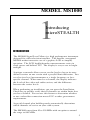
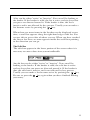
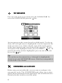
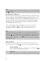
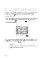
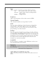
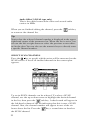
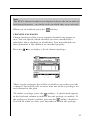
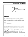
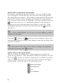
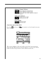
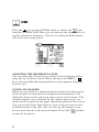
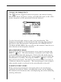
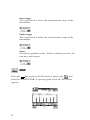
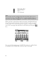
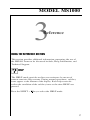
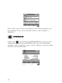
OPERATION MANUAL
MODEL MS1000
SIGNAL LEVEL METER
This document contains information proprietary to
Wavetek. The information in this document
is not to be used or duplicated in any manner without
the prior approval, in writing, of Wavetek.
Wavetek
Communications Division
5808 Churchman Bypass
Indianapolis, IN 46203-6109
(800)851-1198
(317)788-5960
Fax: (317)782-4607
E-Mail: [email protected]
Internet: http://www.wavetek.com
1/96
Manual Part No.
6510-00-0280
1
WARRANTY
Wavetek warrants that all Products manufactured or procured by Wavetek conform to
Wavetek’s published specifications and are free from defects in materials and workmanship
for a period of one (1) year from the date of delivery to the original Buyer, when used under
normal operating conditions and within the service conditions for which they were designed.
This warranty is not transferrable and does not apply to used or demonstration products.
The obligation of Wavetek arising from a Warranty claim shall be limited to repairing, or at
its option, replacing without charge, any assembly or component (except batteries) which in
Wavetek’s sole opinion proves to be defective within the scope of the Warranty. In the event
Wavetek is not able to modify, repair or replace nonconforming defective parts or components
to a condition as warranted within a reasonable time after receipt thereof, Buyers shall receive
credit in the amount of the original invoiced price of the product.
Wavetek must be notified in writing of the defect or nonconformity within the Warranty
period and the affected Product returned to Wavetek’s factory, designated Service Provider,
or Authorized Service Center within thirty (30) days after discovery of such defect or
nonconformity. Buyer shall prepay shipping charges and insurance for Products returned to
Wavetek or its designated Service Provider for warranty service. Wavetek or its designated
Service Provider shall pay costs for return of Products to Buyer.
Wavetek shall have no responsibility for any defect or damage caused by improper storage,
improper installation, unauthorized modification, misuse, neglect, inadequate maintenance,
accident or for any Product which has been repaired or altered by anyone other than Wavetek
or its authorized representative or not in accordance with instructions furnished by Wavetek.
The Warranty described above is Buyer’s sole and exclusive remedy and no other warranty,
whether written or oral, expressed or implied by statute or course of dealing shall apply.
Wavetek specifically disclaims the implied warranties of merchantability and fitness for a
particular purpose. No statement, representation, agreement, or understanding, oral or
written, made by an agent, distributor, or employee of Wavetek, which is not contained in the
foregoing Warranty will be binding upon Wavetek, unless made in writing and executed by
an authorized representative of Wavetek. Under no circumstances shall Wavetek be liable for
any direct, indirect, special, incidental, or consequential damages, expenses, or losses,
including loss of profits, based on contract, tort, or any other legal theory.
Extended Warranty Programs
Extended warranties and service contracts are available for new and currently owned
equipment for an additional cost. Contact the Customer Service Department (800 8511198) for details pertaining to extended warranties and service contracts.
Return Authorization Procedure
The customer MUST obtain a RETURN AUTHORIZATION NUMBER from the
Customer Service Department (800 851-1198) prior to returning any equipment for
warranty or non-warranty repair. Wavetek accepts no liability for any instrument or
subassembly returned to the factory without this number. Any correspondence regarding
returned instruments or subassemblies should be referenced to that number.
2
Contents
Introducing microStealth ............................................................... 5
Introduction ..................................................................................... 5
Getting Acquinted with the Keypad............................................. 7
Getting Acquinted with the Screen .............................................. 9
The Navigator ................................................................................. 12
Configuring microStealth ............................................................... 12
Global Configuration ...................................................................... 13
Measurements Configuration ........................................................ 15
Channel Plan Configuration .......................................................... 18
Using microStealth ......................................................................... 25
Introduction ..................................................................................... 25
Installation ....................................................................................... 25
Selecting Channel Packages .......................................................... 26
Selecting the Test Point ................................................................ 26
Installation Results Summary ........................................................ 27
The Channel List ........................................................................... 28
The Pass/Fail Indicator .................................................................. 28
Channel Measurement ................................................................... 29
Level ................................................................................................ 30
Adjusting the Reference Level ..................................................... 30
Tuning by Channel ........................................................................ 30
Tuning by Frequency .................................................................... 31
Measurement Hold......................................................................... 31
Warning Indicators ......................................................................... 31
Scan .................................................................................................. 32
Moving the Marker......................................................................... 33
Adjusting the Reference Level ..................................................... 33
Adjusting the Scale ......................................................................... 33
Checking Limits ............................................................................. 33
Measurement Hold......................................................................... 35
Reference ........................................................................................ 37
Using the Reference Section ......................................................... 37
Help ................................................................................................. 37
Information ...................................................................................... 38
Technical Support .......................................................................... 39
Appendices ...................................................................................... 41
Appendix A: Specifications ............................................................ 41
Appendix B: Power Management and Battery ............................ 43
Battery Pack Location and Installation ........................................ 43
Charging the Battery Pack ............................................................. 43
Battery Tips .................................................................................... 43
MODEL MS1000
1
Introducing
microSTEALTH
INTRODUCTION
The MS1000 Signal Level Meter is a high performance instrument
designed for cable television installers. The durable, waterproof
MS1000 makes innovative use of a graphics LCD to simplify
operation. The LCD backlight makes measurements easier in
crawl spaces and behind TVs. The display is easy to see in bright
sunlight.
A unique scan mode allows you to see the levels of up to six userdefined carriers on one screen with a pass/fail limit indication. You
can also view level measurements at a single frequency or for a
specific channel. When tuned to a channel, the display indicates
the levels of the video and audio carriers, and the difference
between the carrier levels.
When performing an installation, you can press the Installation
Check key to quickly verify that all channels are within limits that
you have defined. You can use this feature to determine whether
or not a subscriber connection meets FCC or other government
requirements.
A special channel plan building mode automatically determines
which channels are active on your cable system.
The MS1000 tunes from 45 to 550 MHz with an option to extend
the range to 890 MHz.
5
1
7
4
3
6
5
7
2
6
GETTING ACQUAINTED WITH THE KEYPAD
The keypad consists of the following:
• three Soft keys
• a Power key
• four Mode Selection keys
• an Enter key
• eleven Alphanumeric keys
• a Shift key
1. SOFT KEYS
There are three horizontally oriented soft keys located below the
display. The function of each soft key changes depending on the
particular operation being performed and is represented by an
icon immediately above the key.
2.
POWER KEY - ON/OFF
Turns your microStealth on and off.
3. MODE SELECTION KEYS
INSTALLATION MODE
Easily check the channels that you have installed and
verify that they are within limits.
LEVEL MODE
Measure the signal level at a specific channel or frequency.
SCAN MODE
View a spectrum graph of up to six carrier levels.
NAVIGATOR
Instantly "travel" to any mode using the navigator.
7
4.
ENTER KEY
Press this key to terminate your entry or selection.
5. ALPHANUMERIC KEYS
You use the alphanumeric keys to enter data while operating your
microStealth. Notice that these keys have a numeral and up to
three alphabetic characters labeled on them. You can only access
the characters when alphanumeric entry is allowed. In the
alphanumeric entry mode, you sequence through each character
and the numeral by repeatedly pressing the key. You can also
access a set of special characters that do not appear on the keypad
by using the up and down arrows. Once the desired character is
displayed, move the cursor to the next position using the right
arrow. Be sure to terminate your entry by pressing the
key.
6. SHIFT KEY
Some keys perform more than one function. The secondary
function of a key is represented by an icon printed next to it.
Notice that the icons are color coded with the SHIFT key. You
access the secondary function by first pressing the SHIFT key
and then the associated key.
7. SECONDARY FUNCTIONS
CONFIGURE MODE
Configure your microStealth for your own specific needs.
AUTO REFERENCE
Let microStealth automatically set the reference level for
you.
SNAP SHOT
Hold the measurement. The measurement is retained even
if the cable is disconnected from the input.
CLEAR
Clear-out your entry and start over again.
8
BACKLIGHT ON/OFF
Quickly turn the backlight on when it is too dark to see the
display.
POSITIVE/NEGATIVE
Enter positive and negative values (when allowed).
HELP
View a description of each icon found in the current soft
key menu.
Note:
The following keys are not available on the MS1000:
FILE
PRINT
GETTING ACQUAINTED WITH THE SCREEN
There are certain elements of the screen that will become familiar
to you as you use your microStealth.
The Title Bar
Notice the title bar at the very top of the screen. It presents the title
and icon for the current mode you are using.
Title Bar Indicators
You may see indicators appear above the title bar from time to time.
This is what they represent:
This indicator appears in the top right-hand corner of
the screen when you press the SHIFT key. This means
that microStealth will interpret the next key that you press
to be a secondary function.
9
This indicator is displayed to warn you that the battery is
low. When you see this, recharge the battery or change to a
fresh one as soon as possible.
This indicates that the RF synthesizer has become
unlocked. If this condition persists, the unit may need
repair.
The Status Bar
Look for the status bar in the lower portion of the screen. It displays
a bar meter that indicates the charge remaining in your
microStealth's battery. When the battery meter reads low, you will
need to switch to a freshly charged battery soon.
Soft Key Icons
There are three soft keys located immediately below the display.
The function of a soft key is represented by the icon directly above
it.
Note
If the soft key function is not currently available, the icon appears
"grayed" or "dimmed".
Lists
Lists present several items for viewing and/or selecting. Notice that
the currently chosen item is highlighted. You can scroll through the
list using the up and down arrows.
10
A list can be either "active" or "inactive". You can tell by looking at
the border. If the border is solid, the list is active and any keys that
you press are directed toward it. If the border is dim, the list is
inactive and is not affected by key presses. Usually you can make a
list become active by pressing the
key.
When there are more items in the list than can be displayed at one
time, a scroll bar appears along the right-hand edge of the list. You
can use this to get an idea of where you are. When you have reached
the first or last item, an arrow appears inside the scroll box pointing
to the direction you can go.
The Edit Box
The edit box appears in the lower portion of the screen when it is
necessary to enter values into your microStealth.
An edit box can be either "active" or "inactive". You can tell by
looking at the border. If the border is solid, the edit box is active
and any keys that you press are directed toward it. If the border is
dim, the edit box is inactive and is not affected by key presses.
Usually you can make a list become active by pressing the
key.
Be sure to press the
key again when you have finished making
your entry.
11
THE NAVIGATOR
You can easily travel to any mode using the NAVIGATOR. To
access the NAVIGATOR, press the
key.
An icon appears on the screen for each available mode. Use the up,
down, left, and right arrows to highlight the icon that represents the
mode you want to use. Notice that the name of the mode appears
on the lower portion of the screen beneath the status bar. To get a
description of the highlighted mode, press the SHIFT +
key. To
travel to the mode you have highlighted, press any one of the soft
keys or the
key.
Tip
You can also use the numeric keys, 1 through 9 to highlight the
desired icon in the NAVIGATOR screen. Each key corresponds to
an icon in the 3 by 3 matrix.
CONFIGURING microSTEALTH
Before using your microStealth, you may want to configure it for
your specific needs. The CONFIGURE mode allows you to select
global and measurement related preferences and to build and edit a
channel plan that matches your cable plant.
12
To configure your microStealth, press the SHIFT + keys or
choose the
icon from the NAVIGATOR. The following screen
appears:
Configuration settings are divided into three categories; GLOBAL,
MEASUREMENTS, and CHANNEL PLAN. Use the up and
down arrows to highlight the category you want and then press the
key.
Tip
You can also use the left-hand and right-hand soft keys to scroll
through the CONFIGURE categories and then press the middle
soft key to select the highlighted category.
Global Configuration
CONTRAST LEVEL
Adjusts the contrast level of the LCD for optimum viewing.
SHUTOFF TIME-OUT
Sets the amount of inactive time allowed before your microStealth
turns off automatically. This feature is useful for conserving battery
life by preventing the microStealth from being left on accidentally
when it is not in use. You can set the time-out period to 1, 3, or 5
minutes. There is also an "always on" setting that defeats the
automatic shutoff feature if desired.
13
Note
You can manually turn off your microStealth at any time by pressing
the
button.
BACKLIGHT TIME-OUT
Sets the amount of inactive time allowed before the backlight turns
off automatically. The backlight consumes significant power. This
feature conserves battery life by minimizing the amount of time
that the backlight is on. You can set the time-out period to; 5 or 10
seconds. There is an always off setting for when the backlight is
not needed at all. There is also an always on setting that defeats
the backlight time-out feature.
You can manually turn the backlight on or off at any time by
pressing the SHIFT + keys. When manually activated, the
backlight remains on continuously until the unit shuts off.
Tip
You can tell when the backlight is on even in bright sunlight by
looking for the backlight indicator at the left-hand edge of the Title
Bar. The indicator means that the backlight is currently on and
will turn off automatically. The indicator means that the backlight is on and will remain on continuously. If you see no indicator,
the backlight is off.
DIAGNOSTICS
Performs hardware diagnostics and defaults stored preferences to
factory presets. Press the
key to access the diagnostics options.
Factory Default
Sets all stored preferences to factory presets. Press the
key to initiate the default operation.
Important
All stored settings are lost when you perform this operation.
14
Test Display
Exercises all pixels on the LCD for test purposes. Repeated
pressing of the
key sequences the display between all
pixels "on", all pixels "off", and the display test screen.
Measurements Configuration
SIGNAL LEVEL UNITS
Selects the units that will be used for all signal level measurements.
You can select between; dBmV, dBµV and dBm.
PROBE COMPENSATION
This can be used to compensate for losses associated with probe
points found on certain amplifiers. You can enter a value between
-99.9 and +99.9 dB. Probe compensation is added directly to signal
level measurements. The compensation value is indicated in the
upper left-hand corner of the measurement screens. There is no
indication, however, if the compensation value is zero.
Important
The PROBE COMPENSATION value will not affect INSTALLATION or CHANNEL PLAN BUILD mode. Level measurements
made while checking an installation are uncompensated.
FREQUENCY TUNING STEP SIZE
This setting affects the increment/decrement step size when you
are tuning the frequency using the left and right arrows. You can
select a value between 25kHz and 100MHz in steps of 25kHz.
EDIT TEST POINTS
Your microStealth is capable of performing tests at various locations
including; SUBSCRIBER DROP, GROUND BLOCK, TAP, and
USER DEFINED (or CUSTOM). Each test point has its own set
of limits that you can edit. Press the
key to edit the test points.
A list of available test points appears.
15
You can enable or disable each test point in the list. When a test
point is disabled, you cannot use it when performing tests. Use the
up or down arrow to highlight the desired test point. If the highlighted test point is disabled, you can enable it by pressing the
soft key. A check mark appears in the left-hand column to indicate
when a test point is enabled. If the test point is already enabled,
pressing the
soft key disables it.
Tip
You can change the name of the USER DEFINED (CUSTOM)
test point. Notice that the edit box appears when this test point is
highlighted. When you press the
key, the edit box becomes
active and you can enter any name up to fifteen characters long. Be
sure to press the
key when finished to terminate your entry.
You can edit the limits for the highlighted test point by pressing the
soft key. The limits appear on the screen.
16
You can selectively enable or disable each individual limit. When a
limit is disabled, your microStealth excludes it when checking
limits. If the highlighted limit is disabled, you can enable it by
pressing the
soft key. A check mark appears in the left-hand
column to indicate when a limit is enabled. If the limit is already
enabled, pressing the
soft key disables it.
Note
If you disable all of the limits within a test point, the test point
becomes disabled. You cannot enable a test point that has no
enabled limits.
You can edit the value of the highlighted limit by pressing the
key. When the edit box becomes active, enter the desired value. Be
sure to press the
key when finished to terminate your entry.
Press the
soft key to return all limits in the test point to their
factory preset values.
17
Channel Plan Configuration
VIDEO SIGNAL TYPE
Your microStealth is capable of measuring signal levels on NTSC or
PAL video signals. You should make sure that the correct video
type is selected.
CHANNEL SEQUENCE
You can specify whether channels are listed in numeric or frequency order. This setting also affects the sequence in which
channels are tuned in the LEVEL screen when using the left and
right arrows.
Note
The SCAN screen always displays channels in order of frequency
regardless of the CHANNEL SEQUENCE setting.
BUILD CHANNEL PLAN
Your microStealth is capable of learning which channels are on your
cable plant. This allows you to quickly and easily generate a
customized channel plan. Press the
key and let microStealth
learn your system.
Important
Be sure that your microStealth is connected to the cable system
before initiating this procedure.
Step 1
You are asked to enter a name for the channel plan. Using
the edit box, you can enter any name up to fifteen characters long. Be sure to terminate your entry with the
key.
Press the
18
soft key to continue with the next step.
Step 2
There are several base channel plans to use as a foundation
for building your plan. Use the up or down arrows to
highlight the one that is appropriate for your system. Press
the
soft key to continue with the next step.
Step 3
You can tell microStealth what frequency to stop searching
for channels. This will save time when building the plan.
The frequency you enter should be just above the highest
channel on your system. If you are not sure what the
frequency of your highest channel is, just use the default
value that appears in the edit box. If you have entered a
value, be sure to terminate your entry with the
key.
Press the
soft key to begin building the plan.
Upon pressing the
soft key, microStealth begins searching your
system for active channels. A bar graph indicates the percentage of
the channels searched. After the plan has been built, press the
soft key to return to the Channel Plan Configuration screen.
EDIT CHANNEL PLAN
You can edit various parameters for each channel. Press the
key to edit the channels. A list of all the channels in the plan
appears.
19
You must enable a channel in order to perform measurements on it.
A check mark appears in the left-hand column when the channel is
enabled. When you built the plan, microStealth automatically
enabled all the channels it found to be active on your system. You
may want to verify that all your channels have been correctly
soft key to enable/disable the channel
enabled. Use the
highlighted in the list.
There are several parameters that you can specify for each channel.
To do this, highlight the desired channel using the up or down
arrow and press the
soft key or the
for that channel appear.
key. The parameters
Use the up or down arrow to highlight the desired parameter. Press
the
key to edit the selected parameter. After completing your
entry, be sure to press the
key again.
Enabled
As mentioned earlier, a channel must be enabled in order
for it to be measured. This is another place where you can
enable or disable the channel.
20
Type
There are three channel types from which to choose:
TV
-the standard video and audio carriers
DUAL -a video carrier with two independent
audio carriers
SNGL -a single carrier
Frequency
This is the frequency of the video carrier in MHz.
Channel Number
The channel number can range from 1 to 999.
Label
You can enter a label up to four characters in length for
each channel. This label appears next to the channel
number on most screens to help you to remember what
programming is on that channel.
Package
You can organize channels into packages. In the edit box,
you can select any package that is enabled (see the section
on CHANNEL PACKAGES). When you are checking an
installation, you can specify which packages the subscriber
has ordered and your microStealth will verify that the
channels are correctly installed.
Scrambled
If the channel is scrambled, select YES here so that accurate measurements can be made.
Important
microStealth supports several scrambling formats including
the following:
Horizontal Sync Suppression
Audio Offset (TV and DUAL type only)
This is the offset between the video and audio carriers in
MHz.
21
Audio Offset 2 (DUAL type only)
This is the offset between the video and second audio
carriers in MHz.
When you are finished editing the channel, press the
to return to the channel list.
soft key
Tip
Notice that the selected channel number is displayed in the upper
right-hand corner of the parameter list. When the list is active, you
can use the left or right arrows to select the previous or next channel in the plan. You can also use the numeric keys to directly enter
a specific channel number.
SELECT SCAN CHANNELS
Press the
key to specify which carriers will be measured on the
SCAN screen. A list of all enabled channels in the current plan
appears.
Up to six SCAN channels can be selected. To select a SCAN
channel, use the up or down arrow to highlight the desired channel
in the list, then press the
soft key. A check mark will appear in
the left-hand column of the list indicating that this is now a SCAN
channel. Also, the channel number will appear in one of the six
boxes above the list. Press the
the SCAN channel.
22
key a second time to deselect
Note
The SCAN channel numbers are displayed above the list in order of
increasing frequency - not in the order in which they were selected.
When you are finished, press the
soft key.
CHANNEL PACKAGES
Channel packages allow you to organize channels into groups or
tiers. You can specify which channels you have installed for a
subscriber when checking an installation. Your microStealth can
then determine if the channels are installed properly.
Press the
key to display a list of channel packages.
These are the packages that will be available to you when you edit
a channel. You will be able to select from one of these packages for
each channel in the plan.
To enable a package, press the
softkey. A check mark appears
in the left-hand column to indicate that the package is enabled. If
the package is already enabled, pressing the
softkey disables it.
You will be asked to verify your intention to disable the package.
23
Important
The number in the right-hand column of the package list indicates
how many channels are currently using the package. When you
disable a package, all channels using that package default to NONE
(no package).
To edit the name of a package, use the up or down arrow to highlight the desired package and then press the
key. You can then
use the edit box to change the name. Be sure to press the
key
when you are finished to terminate the entry.
Tip
There is no minimum on the number of channels that a package
can contain. If you want, you can create a package for only one
channel.
24
MODEL MS1000
2
Using
microSTEALTH
INTRODUCTION
The best way to learn about microStealth is to use it. Section 2
discusses the individual measurements available with the MS1000.
Each measurement mode discussion includes detailed descriptions
on how to perform the measurement as well as operating controls
and indicators.
INSTALLATION
The INSTALLATION mode allows you to easily check the
channels that you have just installed and verify that they are within
limits. If you have configured channel packages, you can tell your
microStealth which packages the subscriber has ordered and it will
display only those channels.
Press the
key to select the INSTALLATION mode or choose
the
icon from the NAVIGATOR. Your microStealth will begin
measuring all the enabled channels in the plan. A bar graph
indicates the percentage of channels measured. When microStealth
has finished, you can view the results and verify that all channels
are within limits.
25
SELECTING CHANNEL PACKAGES
If you have configured channel packages, a list of available packages will appear. From this list, you can select the packages that
the subscriber has ordered. The number to the right of the package
name tells you how many channels are included in each package.
Use the up or down arrows to highlight a package and then press the
soft key to select it. A check mark appears in the left-hand
column of the list indicating that the package is selected. If the
highlighted package is already selected, pressing the
soft key
deselects it.
Tip
Select “ALL CHANNELS” if you want to include all the enabled
channels in the plan.
Press the
soft key or
when you have finished. Now your
microStealth will only evaluate the channels from the packages that
you have selected.
Tip
You can return to this screen at any time to change your package
selection by pressing the
soft key.
SELECTING THE TEST POINT
The next thing you should do is tell microStealth at which test
point you are located. This determines which set of limits are used.
Press the
soft key to sequence through the available test points.
The test point that you have selected is represented in the upper
portion of the screen by one of the following icons:
Subscriber Drop
Ground Block
Tap
User Defined
26
Note
Be sure that you have enabled all of the test points that you are
interested in using. The
soft key is only available if there is
more than one enabled test point. (see EDIT TEST POINTS).
Important
Only the limits that are enabled in the selected test point are
checked (see EDIT TEST POINTS).
INSTALLATION RESULTS SUMMARY
This is the overall limit check summary for all channels in the
packages that you have selected.
To quickly determine the status of the overall limit check, look at
the PASS/FAIL indicator located in the upper portion of the screen.
This indicates FAIL if any channel is not within the required limits.
For each limit, the worst case actual value is displayed along with a
pass/fail status.
Note
Only the limits that are enabled in the selected test point appear on
this screen. If there are no enabled test points, this screen will not
be available. You can however, view the CHANNEL LIST and
CHANNEL MEASUREMENT screens described below.
27
THE CHANNEL LIST
Press the
screen.
soft key or
to sequence to the channel list
Tip
In addition to using the
and
keys, you can also use the
left and right arrows to sequence through the results screens.
The channel list provides essential information about each channel.
In the list you will find the channel number in the first column
followed by the label. The level of the video carrier is in the next
column. The package in which the channel is contained is displayed in the fourth column. Finally, the overall limits pass/fail
result for the channel is found in the last column.
THE PASS/FAIL INDICATOR
Use the PASS/FAIL indicator located directly above the channel
list to quickly determine whether the highlighted channel has
passed the limits check. If the channel failed, you can identify the
reason(s) for the failure by looking at the symbols that appear in this
indicator.
28
Adjacent Channel Failures
lower adjacent channel level
upper adjacent channel level
both upper and lower adjacent channel
levels
Video Level Failures
video level too high
video level too low
DVA Failures
DVA too high
DVA too low
CHANNEL MEASUREMENT
Press the
soft key or
ment screen.
to sequence to the channel measure-
This screen displays video and audio carrier level measurements
along with the DVA for the selected channel. Use the up or down
arrows to select the previous or next channel in the list.
29
LEVEL
Press the
key to select LEVEL mode or choose the
icon
from the NAVIGATOR. Here you can measure the signal level of a
specific channel or frequency. The level is indicated both numerically and on an analog meter.
ADJUSTING THE REFERENCE LEVEL
You can adjust the reference level setting of the analog bar meter
using the up and down arrows. When you press the SHIFT +
keys, your microStealth automatically sets the optimum reference
level for you.
TUNING BY CHANNEL
When you are tuned to a channel, both the video and audio carriers
of the channel are measured and displayed simultaneously. The
difference between the video and audio carriers is also shown. The
channel number, type and label for the channel that you are currently tuned to appear in the upper right-hand portion of the screen.
You can use the left or right arrows to tune to the previous or next
enabled channel in the plan. You can also use the numeric entry
keys to tune directly to the desired channel. Press the
to tune by frequency.
30
soft key
TUNING BY FREQUENCY
The
soft key toggles between frequency and channel tuning.
When you choose frequency tuning, microStealth tunes to the video
carrier frequency of the previously selected channel.
Use the left and right arrows to tune your microStealth. The
frequency increments or decrements by the step size that you have
specified in the Measurement configuration (see FREQUENCY
TUNING STEP SIZE). You can also use the numeric entry keys to
tune directly to the frequency desired.
MEASUREMENT HOLD
You can freeze the level measurement at any time by pressing the
SHIFT +
keys. The measurement is retained even if the cable
is disconnected from the input port. Notice that the mode icon in
the upper left-hand portion of the screen appears inverted while the
measurement is on hold. Pressing the SHIFT +
keys a second
time releases the hold. The hold is also released when you tune to
a different channel or frequency. The measurement is not retained
when another mode is selected or the microStealth is shut off.
WARNING INDICATORS
If the current measurement is inaccurate due to an out-of-range
condition or hardware failure, microStealth warns you by dimming
the numeric measurement value and displaying one of the following
warning indicators:
31
Over-range
The signal level is above the measurement range of the
instrument.
Under-range
The signal level is below the measurement range of the
instrument.
Error
A hardware problem exists. If this condition persists, the
unit may need repair.
SCAN
Press the
key to select SCAN mode or choose the
icon
from the NAVIGATOR. A spectral graph of the SCAN carriers
appears.
32
Important
You can choose which carriers appear on this screen when you
configure your channel plan (see SELECT SCAN CHANNELS).
MOVING THE MARKER
You can view up to six carriers. A vertical marker appears over the
currently selected carrier. The channel number, type, and label for
the selected carrier appear in the upper right-hand portion of the
screen. The frequency and level of the selected carrier can be seen
directly beneath the graph. You can use the left or right arrows to
select the previous or next carrier.
ADJUSTING THE REFERENCE LEVEL
The current reference level setting is displayed above the graph.
This is the level at the very top line. You can adjust the reference
level using the up and down arrows. When you press the SHIFT +
keys, your microStealth sets the optimum reference level for
you.
ADJUSTING THE SCALE
The current scale setting is displayed above the graph. You can
adjust the scale to provide the best view of the carrier levels by
pressing the
and
soft key. A new set of soft keys appear. Use the
soft keys to increment and decrement the scale
value. Press the
soft key when you are finished.
CHECKING LIMITS
You can verify that the carrier levels are within limits. First you
need to tell microStealth which test point you are checking. This
determines which set of limits are used. Press the
soft key to
sequence through the available test points. The test point that you
have selected is represented in the upper portion of the screen by
one of the following icons:
33
Subscriber Drop
Ground Block
Tap
User Defined
Note
Be sure that you have enabled all of the test points that you are
interested in using. The
soft key is only available if there is
more than one enabled test point. (see EDIT TEST POINTS).
When you have selected the proper test point, microStealth shows
the minimum and maximum carrier level limits for that test point
on the graph. The out-of-limit portion appears as diagonal "hash"
areas. You can toggle the hash lines on and off by pressing the
key.
You can quickly check to see if all SCAN carriers are within limits
by looking at the PASS/FAIL indicator above the graph.
34
MEASUREMENT HOLD
You can freeze the SCAN measurement at any time by pressing the
SHIFT +
keys. The measurement is retained even if the cable
is disconnected from the input port. Notice that the mode icon in
the upper left-hand portion of the screen appears inverted while the
measurement is on hold. Pressing the SHIFT +
keys a second
time releases the hold. The measurement is not retained when
another mode is selected or the microStealth is shut off.
35
MODEL MS1000
3
Reference
USING THE REFERENCE SECTION
This section provides additional information concerning the use of
the MS1000. Items to be discussed include; Help, Information, and
Technical Support.
HELP
The HELP mode provides on-line user assistance by means of
context-sensitive help screens. During normal operations, soft key
icons appear at the bottom of the display. Each help screen describes the condition of the soft key icons at the time HELP was
pressed.
Press the SHIFT +
key to select the HELP mode.
37
Next to the icon is a brief description of the function that the soft
key performs. If an icon is currently inactive "not available" is
displayed.
INFORMATION
Choose the
icon from the NAVIGATOR. Here you can view
information concerning your MS1000. The type of information
includes; model, frequency range, serial #, firmware version, calibration date, and channel plan.
38
TECHNICAL SUPPORT
Although we've worked hard to make the MS1000 as easy-to-use as
possible, the wide range of cable television applications can make
proper operation a difficult task. If you have a problem using your
unit you can contact Wavetek's Technical Support for help. You can
reach Wavetek's Technical Support, Monday through Friday between 8 am and 5 pm at (317) 788-5960. Wavetek also maintains
technical support on the Internet. You can leave messages and a
Technical Support Specialist will get back to you at Internet address:
[email protected].
If you received your unit and found it to be damaged or incomplete
in any way, phone Wavetek immediately. Save the shipping carton
and packing material in the event that you have to return it.
FOR CUSTOMER SERVICE call: WAVETEK (800) 851-1198,
International Customers, contact your local Wavetek Representative.
39
MODEL MS1000
A
Appendix A:
Specifications
SPECIFICATIONS
Frequency
Range:
Accuracy:
Tuning Resolution:
45 to 550 MHz; 45 to 890 MHz (optional)
+10kHz @ 25°C; (+20 kHz over temp.)
25 kHz
Level Measurement
Range:
Resolution:
Accuracy:
-20 to +45 dBmV
0.1 dB
+0.75 dB Flatness; +0.75 dB Linearity
Six Channel Mode
Number of Channels:
Scan Rate:
6
< 1 second
General
Dimensions:
4.25" (W) x 10" (H) x 2.5" (D)
Weight:
0.8 kg (1.75 lb.)
Operating Temp. Range:
-10 to +50°C (14 to 122°F)
Water Resistance:
Meets or exceeds MIL-STD-810D
(Method 506.2)
41
Powering
Battery Life:
Charge Time:
3 hours continuous (backlight off), re
placeable battery cartridge
16 hours with unit off; 30 hours slow
charge (with unit operating)
Standard Accessories
4010-00-0114: microStealth AC/DC charger/adapter
1219-00-1223: Battery cartridge for microStealth
Options
MSUHF: Frequency extension to cover range: 45 to 890 MHz
MSSUB: Frequency extension to include 5 to 45 MHz
1019-00-0476: microStealth Soft Carrying Case
1019-00-0470: Cloning Cable
1019-00-0480: Multiple battery cartridge charger
4010-00-0114: Charger/Adapter 120VAC to 18 VDC
1019-00-0473: Charger/Adapter 220VAC to 18 VDC
1219-00-0123: Field replaceable microStealth battery cartridge
P-Stealth: Portable serial thermal fusion printer kit
1019-00-0468: P-Stealth printer cable
1019-00-0467: Generic serial printer cable - 25 pin male connector
1019-00-0469: microStealth to PC Cable
42
MODEL MS1000
B
Appendix B:
Power
Management
and Battery
Battery Pack Location and Installation
The MS1000 battery pack is located on the back of the unit. To
remove or replace the battery pack, pull the notched tab downward,
and lift up the battery pack.
To install the battery pack, insert the bottom of the pack into the
groove and press down on the battery pack until it clicks into place.
Charging the Battery Pack
To recharge the battery pack, plug the AC adapter into the unit.
The unit will reach fully charged in 16 hours with unit off, and 30
hours with unit operating.
Battery Tips
The MS1000 is shipped from the factory only with a light charge.
You should recharge the battery upon receipt of your unit to ensure
a full charge.
To maximize battery life, set Auto Shutoff to 1 minute and Backlight Shutoff to "always off".These items are described in the
Global Configuration section.
43