1
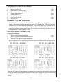
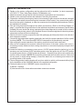
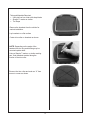
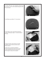
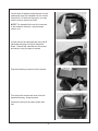
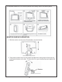
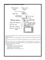
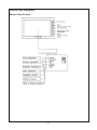
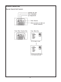
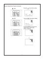
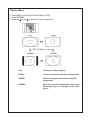
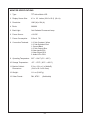
®
ELECTRONICS CORP.
LCM500NP 5 Inch Monitor
with
2 Video Input Capability
Installation and Operation Manual
Important Notice
It is unlawful in most jurisdictions for a person to
drive a motor vehicle which is equipped with
a television viewer or screen that is located
in the motor vehicle at any point forward of
the back of the driver's seat, or that is visible
directly or indirectly, to the driver while operating the vehicle.
CAUTION
1.
2.
3.
4.
5.
Do not operate the monitor at temperatures below 32°F (0°C) or above 104°F (40°C).
Keep the monitor clean and dry.
Always seek qualified personnel to perform repairs. Never attempt your own repairs.
Do not drop the monitor or expose to strong impacts.
Do not expose to direct sunlight for extended periods of time.
The Materials included in this package:
1.
2.
3.
4.
5.
6.
7.
8.
9.
LCM500NP Monitor
Remote Control Unit
Interconnection Box (AVX-6865)
Monitor Cable Assembly 16 Feet (5 Meters)
Power Cable Assembly
Surface Mount (S2)
Headrest Shroud
Trim Ring For Shroud
Removal Tool
(1pc)
(1pc)
(1pc)
(1pc)
(1pc)
(1pc)
(1pc)
(1pc)
(1pc)
LCM500NP SYSTEM OVERVIEW
The LCM500NP is comprised of a 5" Thin Film Transistor (TFT) Liquid Crystal Display ( LCD)
monitor. The monitor display is a widescreen display (16:9 Aspect Ratio ) that allows the user
to select from two video sources (Not Supplied). The housing has a built-in location for the
installation of an optional infrared audio transmitter ( Audiovox IRT 456, IRT 457) for use with
optional two channel wireless headphones. The monitors will display all functions with the
comprehensive On Screen Display (OSD).
OPTIONAL AUDIO CONNECTION
Required Materials:
1.
2.
3.
IRT456 (CHA) Infrared Transmitter
IRT457 (CHAB) Infrared Transmitter Remote
WHS200 Two Channel Infrared Headphones
(1pc)
(1pc)
Before installing the IRT boards gently bend the three IR LEDs closest to the center of the
vehicle toward the center of the vehicle.
IRT 456 CH A BEFORE
IRT 457 CH B BEFORE
IRT 456 CH A AFTER
IRT 457 CH B AFTER
Insert the IRT boards into their respective compartments in the monitor housing and insert the plug
into the IRT board. When the user switches the video source utilizing the ON/OFF/MODE switch,
the A/B switch on the WHS200 headphones must also be switched to select the desired audio
source.
-1-
VEHICLE PREPARATION:
1) Decide on the system configuration and the options that will be installed (i.e.what components,
VCP, DVD, TV Tuner, Video Game, Monitor, FM Modulator, etc.).
2) Read the manuals and get familiar with the electrical requirements and connections.
3) Decide on the mounting locations and methods of mounting the products.
4) Prepare the vehicle by removing any interior trim necessary to gain access to the vehicle's wiring as
well as all areas where interconnecting wire harnesses will be located. If any access holes need to
be cut into the vehicle, headrests, or other trim components, this should be performed now. (Refer to
the Installation Procedure).
5) Run the wiring harnesses throughout the vehicle as necessary. (Refer to the Wiring Diagram on
page 7, as well as the wiring instructions for the individual components and accessory options being
installed). Be sure, that all the wiring is protected from sharp edges and is routed in such a manner
that it will not be pinched, when it is fully installed. Be sure to leave enough slack in the wiring at each
component to allow sufficient working room.
6) Remove all the A/V system components from their packaging and then place them in the vehicle at
their respective locations.
7) Connect all the components together (electrically) and verify the proper operation of all the system
functions. NOTE: This is best done BEFORE the components are permanently mounted.
8) After verifying the proper operation of the system, proceed to mount each component.
9) When all the components are mounted, recheck the function of the entire system to be sure it is
functioning correctly. Make sure that no wiring was pinched, or connected improperly during the final
installation.
10) Locate the following: an accessory power source (+12VDC present when the ignition key is in the
accessory and run positions). 0VDC should be present, when the ignition key is in the OFF position.
A constant power source (+12VDC present at all times). Generally, these wires can be found at the
ignition switch or fusebox. (NOTE: Ensure that the power leads are fused at the source. Failure to do
so may result in vehicle wiring damage.) Ground the black wire to a chassis ground close to the
mounting location of AV sources.
11) The mounting method, and the location will vary from vehicle to vehicle, so this manual will only focus
for the installation of the LCM500NP Monitor in the supplied configuration.
12) The best location for the LCM500NP System components are:
a) Monitor : Headrest
b) Interconnection Box: Under either seat where monitors are located.
-2-
Tools and Materials Required:
• Utility knife or box cutter with sharp blade
• Sharpie™ marker or similar
• Tie Wraps
Remove the headrest from the vehicle for
easiest installation.
Lay headrest on a flat surface
Center trim collar on headrest as shown.
NOTE: Depending on the angle of the
headrest the trim ring and housing may be
mounted upside down.
Using a Sharpie™ marker or similar marking
pen, mark headrest material along the
interior of the trim collar.
Remove the trim collar and mark an “X” from
corner to corner as shown
-3-
Using the utility knife, cut the headrest material along
the “X” lines. Do not cut the material along the other
lines at this time.
This will leave you with an “X” cut as shown.
Pull the flaps up and cut the foam beneath the
material to the proper depth. Cut all four sides of
the foam.
Using your fingers, tear the foam out of the
headrest leaving a recess where the shell
will be inserted.
At this point you will need to install the
harness up through the area into the recess.
It may be helpful to follow one of the posts
and tie wrap it to the post for restraint.
-4-
Lay the flaps of headrest material down into the
recess and insert the clamshell into the recess.
Check for fit. If it does not fit properly, you may
need to remove some more foam.
NOTE: The clamshell will need to be secured
to the headrest, either by using tie straps,
screws, ect..
If used, remove the clamshell and insert the IR
transmitter and plug into the IR transmitter
board. Reinsert the clamshell into the recess
and secure using tie wraps or screws.
Plug the remaining connector into the monitor.
Turn the monitor around and insert it into the
clamshell housing. Snap into place.
Connect the wiring to the video system and
test.
-5-
The supplied Release Key is for removing monitor from housing. Refer to the drawing below.
MONITOR SURFACE MOUNTING:
1. Slide the monitor onto the mount S2 and tighten using the fastener.
2. Firmly attach surface mount to a flat surface and adjust the viewing angle of the monitor by
loosening the fastener on the side. Tilt the monitor for a good viewing angle and retighten the
fastener.
Fastener
-6-
LCM500NP SYSTEM WIRING DIAGRAM
1.) Make sure the LCM500NP has been installed properly, as described in the procedures as stated on
pages 2, 3, and 5.
2.) Plug the 15 pin connector into the jack labelled -15 pin to MONITOR on the AVX-6865 Interconnection
Box.
3.) Connect the 2 pin connector to the jack labelled IR POWER output on the AVX-6865 Interconnection
Box.
4.) Connect the video source to the jack labelled VIDEO IN 1 on the AVX-6865 Interconnection Box.
5.) Connect the audio source to the 2 RCA connectors that are incorporated in the Monitor Cable
Assembly (for optional audio connection).
6.) Power Connections:
a) Red (ACC): Connect to switched 12Vdc.
b) Yellow (Batt): Connect to constant 12Vdc.
c) Blue (Remote Out): 12Vdc output.
d) Black (Ground): Connect to chassis ground.
-7-
Controls and Indicators
Monitor Panel Controls
-8-
Remote Control Unit
Remote Control Unit Controls
-9-
Remote Control Unit Controls Continued
KEY
Press the
KEY
Press the
to the desired setting
to the desired setting
Press the MODE key to select the
desired video source input
(Input 1 or Input 2)
-10-
Display Mode
1. Press MENU to get the On Screen Display (OSD).
2. Select FORMAT.
3. Press the
or the to switch the screen aspect ratio.
FULL:
ZOOM:
16:9 picture is fully displayed.
Picture is stretched vertically and horizontally.
CINEMA:
Picture is displayed with uniform horizontal
enlargement.
NORMAL:
When 4:3 pictured is displayed on a wide screen,
black bands appear on the right and left of the
picture
-11-
OPERATING INSTRUCTIONS
1. POWER ON/OFF/MODE
Press the POWER button to turn power on.
Pressing the POWER button again momentarily will change video inputs.
Press the for NTSC input.
Press the
for PAL input.
Press and hold the POWER button for three seconds to turn power off.
2.
Scroll Up Button
This button is used to increase selected menu items (Brightness, Contrast, Color, Tint,
[NTSC] Only) This button will also switch selected items (DIM, RESET, FORMAT).
3.
Scroll Down Button
This button is used to decrease selected menu items (Brightness, Contrast, Color, Tint,
[NTSC] Only) This button will also switch selected items (DIM, RESET, FORMAT).
4. MENU Button
Press the MENU button once to display the menu On Screen Display.
Press the button again until the desired menu item is highlighted.
Use the or
to adjust or switch the selected item. The On Screen Display menu will disappear
if no buttons are pressed for four seconds.
-12-
MONITOR SPECIFICATIONS
1. Type :
TFT Active Matrix LCD
2. Display Screen Size :
4.3 x 2.5 inches (109.2 x 63.5) (W x H)
3. Resolution:
1200 (W) x 234 (H)
4. Pixels:
280,800
5. Back Light :
Cold Cathode Fluorescent Lamp
6. Power Source :
+12 VDC
7. Power Consumption :
510 mA, 7W
8. Connection Terminals :
1-12 Vdc Constant -Yellow
1-12 Vdc Switched -Red
1- Ground-Black
1-12 Vdc Output -Blue
2-Video Inputs-RCA
1-Video Output-RCA
2- Audio L/R In-RCA
9. Operating Temperature : 32°F – 104°F (0°C – 40°C)
10. Storage Temperature :
-4°F – 176°F (-20°C – +80°C)
11. Monitor Cabinet :
Dimensions
5.3 in x 3.3 in x 1 in (WxHxD)
(134.6 x 83.2 x 25.4 mm)
12. Weight :
11.1 oz (314.67g)
13. Video Format :
PAL, NTSC
(Switchable)
-13-
F o r C ustom er S e rvice
Visit O u r W eb site A t
999.audiovox.com
P ro duc t Inform a tio n, P h otos ,
FA Q ’s O w ner ’s M a nua ls
© Copyright 2001 Audiovox Electronics Corp. 150 Marcus Blvd. Hauppauge, NY 11788
128-6244