1
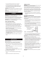
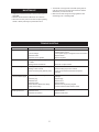
6” Buffer
241-1450
• Use recommended accessories. Use of improper
accessories may cause risk of injury to persons.
• Do not overtighten wheel nut. Replace defective wheel
immediately. Use only flanges supplied with the buffer.
• Handle the workpiece correctly.
POWER SOURCE
WARNING: Do not connect buffer to the power source until
all assembly steps have been completed.
The motor is designed for operation on the voltage and frequency specified. Normal loads will be handled safely on voltages not more than 10% above or below specified voltage.
Running the unit on voltages which are not within range may
cause overheating and motor burn-out. Heavy loads require
that voltage at motor terminals be no less than the voltage
specified on nameplate.
CAUTION: Think safety! Safety is a combination of operator
common sense and alertness at all times when tool is being
used.
WARNING: Do not attempt to operate tool until it is completely assembled according to the instructions.
• Power supply to the motor is controlled by a single pole
locking rocker switch. Remove the key to prevent unauthorized use.
ASSEMBLY
CAUTION: Do not attempt assembly if parts are missing.
Use this manual to order replacement parts.
GROUNDING INSTRUCTIONS
WARNING: Improper connection of equipment grounding
IMPORTANT: Do not attempt assembly if parts are missing.
Use this manual to order replacement parts.
• Check with a qualified electrician if grounding instructions
are not understood or if in doubt as to whether the tool is
properly grounded.
• This tool is equipped with an approved 3-conductor cord
rated at 150V and a 3-prong grounding type plug (Figure 1)
for your protection against shock hazards.
• Grounding plug should be plugged directly into a properly
installed and grounded 3- prong grounding-type receptacle,
as shown (Figure 1).
Buffer comes completely assembled with hex nuts, wheel
flanges and spacers (Key. Nos. 1, 2, and 3) packed separately.
One spiral sewn wheel and one soft wheel are included.
conductor can result in the risk of electrical shock. Equipment
should be grounded while in use to protect operator from
electrical shock.
INSTALL BUFFING WHEELS
To install buffing wheels on the buffer:
• Remove plastic protective sleeves from armature shaft
• Slide spacer (Key. No. 3) onto armature shaft. Spacers are
not required when mounting several wheels to shaft.
• Slide inner wheel flange (Key. No. 2) onto armature shaft.
• Slide buffing wheel on to the armature shaft and butt it
against the inner wheel flange.
• Slide the outer wheel flange (Key. No. 2) and butt the flat
side of the flange against the buffing wheel.
• Tighten hex nut (Key. No. 3)on to the armature shaft. Make
sure the buffing wheel is firmly held in place and the hex nut is
snug against the outer wheel flange. Use additional spacers
(not supplied) if required.
• Install buffing wheel on other side of buffer as mentioned
above.
Properly Grounded Outlet
Grounding Prong
3-Prong Plug
Figure 1 - 3-Prong Receptacle
• Do not remove or alter grounding prong in any manner. In
the event of a malfunction or breakdown, grounding provides a path of least resistance for electrical shock.
WARNING: Do not permit fingers to touch the terminals of
plug when installing or removing from outlet.
• Plug must be plugged into matching outlet that is properly
installed and grounded in accordance with all local codes and
ordinances. Do not modify plug provided. If it will not fit in outlet, have proper outlet installed by a qualified electrician.
• Inspect tool cords periodically, and if damaged, have
repaired by an authorized service facility.
• Green (or green and yellow) conductor in cord is the
grounding wire. If repair or replacement of the electric cord
or plug is necessary, do not connect the green (or green
and yellow) wire to a live terminal.
• Where a 2-prong wall receptacle is encountered, it must be
replaced with a properly grounded 3-prong receptacle
installed in accordance with National Electric Code and
local codes and ordinances.
INSTALLATION
MOUNT BUFFER
Buffer must be mounted to a solid horizontal surface (hardware not provided). To mount buffer to metal pedestal:
• Align mounting holes with corresponding holes in pedestal
• Insert a ¼-20 x 1¼ “ hex head bolt with flat washer through
base of buffer.
• Place a ¼ “ flat washer and ¼ “ -20 hex nut from the bottom
of pedestal onto the bolt.
• Tighten until base is flush with the pedestal.
• Using second nut on each bolt, jam tighten against the first
to prevent loosening by vibration.
To mount buffer to wooden bench:
• Use ¼ x 1¼ “ wood screws with flat washers beneath
heads.
• Tighten screws until base is flush with bench top.
WARNING: This work should be performed by a qualified
electrician.
3
SPECIFICATIONS
A temporary 3-prong to 2-prong grounding adapter (see
Figure 2) is available for connecting plugs to a two pole outlet
if it is properly grounded.
Make Sure
Grounding Lug
This Is
Adapter
Connected
3-Prong Plug
To A Known
Ground
Figure 2 - 2-Prong Receptacle with Adapter
MODEL 241-1450
6“ BUFFER
The buffer is assembled with motor and wiring installed as an
integral part of the tool.
Horsepower . . . . . . . . . . . . . . . . . . . . . . . . . . . . . . . . . . . . . . . . 3/4
Voltage . . . . . . . . . . . . . . . . . . . . . . . . . . . . . . . . . . . . . . . . . . .120
Amperes . . . . . . . . . . . . . . . . . . . . . . . . . . . . . . . . . . . . . . . . . .4.8
Hertz . . . . . . . . . . . . . . . . . . . . . . . . . . . . . . . . . . . . . . . . . . . . . 60
Phase. . . . . . . . . . . . . . . . . . . . . . . . . . . . . . . . . . . . . . . . . . Single
RPM . . . . . . . . . . . . . . . . . . . . . . . . . . . . . . . . . . . . . . . . . . . . 3450
Rotation (viewed from left side) . . . . . . . . . . . . . . . . . .Clockwise
Weight . . . . . . . . . . . . . . . . . . . . . . . . . . . . . . . . . . . . . . . . . 18 lbs
2-Prong
Receptacle
• Do not use a 3-prong to 2-prong grounding adapter unless
permitted by local and national codes and ordinances.
(A 3-prong to 2-prong grounding adapter is not permitted in
Canada.) Where permitted, the rigid green tab or terminal on
the side of the adapter must be securely connected to a
permanent electrical ground such as a properly grounded
water pipe, a properly grounded outlet box or a properly
grounded wire system.
WHEELS SIZE
Diameter. . . . . . . . . . . . . . . . . . . . . . . . . . . . . . . . . . . . . . . . . . . . . .6 “
Bore . . . . . . . . . . . . . . . . . . . . . . . . . . . . . . . . . . . . . . . . . . . . . . . . . 1/2“
OPERATION
• Many cover plate screws, water pipes and outlet boxes are
not properly grounded. To ensure proper ground, grounding
means must be tested by a qualified electrician.
DESCRIPTION
The 6 “ Buffer is equipped with totally enclosed 3/4HP motor
and single-speed motor. Armature assembly is dynamically
balanced for smooth operation. Motor housing is compact
so long pieces of work can press against both wheels
without touching the motor frame.
EXTENSION CORDS
• The use of any extension cord will cause some drop in voltage and loss of power.
• Wires of the extension cord must be of sufficient size to
carry the current and maintain adequate voltage.
WARNING: Always wear safety glasses complying with
United States ANSI Z87.1 before commencing power tool
operation. Safety glasses are available through your Sears
catalog.
• Load buffing compound, appropriate for your workpiece,
onto the wheel.
• Carefully guide workpiece into wheel.
• Keep a steady, moderate pressure on the work piece and
keep it moving at an even pace for smooth buffing.
• Pressing too hard overheats the motor and prematurely
wears down the buffing wheels.
• Use the table to determine the minimum wire size (A.W.G.)
extension cord.
• Use only 3-wire extension cords having 3-prong grounding
type plugs and 3-pole receptacles which accept the tool
plug.
• If the extension cord is worn, cut, or damaged in any way,
replace it immediately.
Extension Cord Length
Wire Size . . . . . . . . . . . . . . . . . . . . . . . . . . . . . . . . . . . A.W.G.
Up to 25 ft. . . . . . . . . . . . . . . . . . . . . . . . . . . . . . . . . . . . . . . 18
25 to 50 ft. . . . . . . . . . . . . . . . . . . . . . . . . . . . . . . . . . . . . . . 16
• The buffing wheel should rotate into object being polished.
NOTE: Using extension cords over 50 ft. long is not
recommended.
ELECTRICAL CONNECTIONS
WARNING: All electrical connections must be performed by
a qualified electrician. Make sure tool is off and disconnected
from power source while motor is mounted, connected, reconnected or anytime wiring is inspected.
4
• The threads on the right side of the buffer (facing unit) are
right hand; threads on the left side are left hand. Hold the
wheels firmly to loosen the hex nut.
MAINTENANCE
• Replacement wheels must have a minimum rated speed of
3450 RPM.
• Make sure hex nuts are tight and snug against the outer
wheel flange prior to restarting buffer.
• Maximum wheel diameter for Model No. 241-1450 is 6 “.
• Disconnect unit from power source before replacing buffing
wheels or before performing any maintenance work.
TROUBLESHOOTING
SYMPTOM
Buffer won’t start
POSSIBLE CAUSE(S)
1. Blown line fuse or tripped circuit breaker 1. If fuse is blown, replace with fuse of proper size. If
breaker tripped, reset it
2. Check power supply for voltage and correct as needed
2. Low line voltage
3. Replace switch
3. Defective switch
4. Replace capacitor
4. Defective, blown capacitor
CORRECTIVE ACTION
Excessive vibration
1. Improper mounting of buffing wheel
on buffer
2. Buffing wheels not balanced
1. Remount
Motor overheating
1. Excess pressure required to buffing
2. Buffing on side of wheel
3. Motor not turning freely (without power)
1. Replace wheel
2. Perform buffing only on face of wheel
3. Clean around wheels and shaft and/or replace
bearings
1. Overloading due to binding
Fuses are being blown
or circuit breakers tripped
2. Defective plug
3. Defective cord
4. Defective switch
5. Motor wired for different line voltage
6. Faulty internal wiring
Buffer will not operate in
variable speed mode
2. Remount or replace wheels
1. Clean around wheels and shaft and/or replace
bearings
2. Replace plug
3. Replace cord
4. Replace switch
5. Rewire motor as per wiring diagram
6. Contact authorized Sears Service Center
1. Replace switch
2. Replace sensor
3. Replace circuit board
1. Defective variable speed switch
2. Defective sensor
3. Defective circuit board
5
Model 241-1450
Figure 3 - Replacement Parts Illustration for 6” Buffer
6