1
HP ENTERPRISE VIRTUAL ARRAY FAMILY
WITH VMWARE VSPHERE 4.0 , 4.1 AND
5.0 CONFIGURATION BEST PRACTICES
Technical white paper
Table of contents
Executive summary............................................................................................................................... 3
The challenges .................................................................................................................................... 3
Key concepts and features .................................................................................................................... 4
ALUA compliance ............................................................................................................................ 4
Configuring EVA arrays........................................................................................................................ 6
Using Command View EVA ............................................................................................................... 6
Running Command View EVA within a VM ......................................................................................... 7
Using the Storage Module for vCenter ................................................................................................ 8
Array hardware configuration and cabling ........................................................................................... 10
Disk group provisioning ...................................................................................................................... 13
Formatted capacity......................................................................................................................... 13
Sparing overhead and drive failure protection level ........................................................................... 13
Application-specific considerations ................................................................................................... 14
Storage optimization ...................................................................................................................... 15
Vdisk provisioning ............................................................................................................................. 17
Implementing multi-pathing in vSphere 4.x ............................................................................................ 18
Multi-pathing in ESX 3.5 or earlier ................................................................................................... 18
Multi-pathing in vSphere 4.x ............................................................................................................ 20
Best practices for I/O path policy selection ....................................................................................... 24
Configuring multi-pathing.................................................................................................................... 24
Displaying the SATP list .................................................................................................................. 26
Connecting to an active-active EVA array in vSphere 4 ...................................................................... 28
Connecting to an active-active EVA array in vSphere 4.1 ................................................................... 30
Caveats for multi-pathing in vSphere 4.x ........................................................................................... 32
Upgrading EVA microcode ............................................................................................................. 35
Overview of vSphere 4.x storage ........................................................................................................ 35
Using VMFS .................................................................................................................................. 36
Using RDM .................................................................................................................................... 36
Comparing supported features......................................................................................................... 37
Implementing a naming convention .................................................................................................. 37
Sizing the vSphere cluster ............................................................................................................... 40
Aligning partitions .......................................................................................................................... 40
Enhancing storage performance .......................................................................................................... 41
Optimizing queue depth ................................................................................................................. 41
Using adaptive queuing .................................................................................................................. 41
Using the paravirtualized virtual SCSI driver...................................................................................... 42
Monitoring EVA performance in order to balance throughput .............................................................. 42
Optimizing I/O size ....................................................................................................................... 44
Summary of best practices .................................................................................................................. 45
Summary .......................................................................................................................................... 47
Glossary ........................................................................................................................................... 48
Appendix A – Using SSSU to configure the EVA .................................................................................... 50
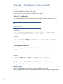
Appendix B – Miscellaneous scripts/commands .................................................................................... 52
Setting I/O path policy ................................................................................................................... 52
Changing the default PSP ................................................................................................................ 52
Configuring the disk SCSI timeout for Windows and Linux guests......................................................... 52
Appendix C – Balancing I/O throughput between controllers.................................................................. 54
Appendix D – Caveat for data-in-place upgrades and Continuous Access EVA ......................................... 59
Appendix E – Configuring VMDirectPath I/O for Command View EVA in a VM ........................................ 61
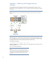
Sample configuration ..................................................................................................................... 61
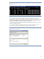
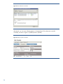
Configuring the vSphere server ........................................................................................................ 64
Configuring the array ..................................................................................................................... 71
Configuring the VM ........................................................................................................................ 71
For more information .......................................................................................................................... 74
Executive summary
The HP Enterprise Virtual Array (EVA) family has been designed for mid-range and enterprise
customers with critical requirements to improve storage utilization and scalability. EVA arrays can
fulfill application-specific demands for transactional I/O performance, while supporting easy capacity
expansion, instantaneous replication, and simplified storage administration.
The combination of an EVA array, HP Command View EVA software and VMware vSphere 4 and 5
provides a comprehensive solution that can simplify management and maximize the performance of a
vSphere infrastructure.
HP continues to develop and improve best practices for deploying P6000/EVA arrays with vSphere 4
and 5. This white paper describes a broad range of best practices for a Fibre Channel (FC)
implementation; iSCSI and Fibre Channel over Ethernet (FCoE) implementation are outside the scope
of this paper.
Target audience: vSphere and SAN administrators that are familiar with the vSphere infrastructure
and virtual storage features, the EVA array family, and Command View EVA.
DISCLAIMER OF WARRANTY
This document may contain the following HP or other software: XML, CLI statements, scripts,
parameter files. These are provided as a courtesy, free of charge, “AS-IS” by Hewlett-Packard
Company (“HP”). HP shall have no obligation to maintain or support this software. HP MAKES NO
EXPRESS OR IMPLIED WARRANTY OF ANY KIND REGARDING THIS SOFTWARE INCLUDING ANY
WARRANTIES OF MERCHANTABILITY, FITNESS FOR A PARTICULAR PURPOSE, TITLE OR NONINFRINGEMENT. HP SHALL NOT BE LIABLE FOR ANY DIRECT, INDIRECT, SPECIAL, INCIDENTAL OR
CONSEQUENTIAL DAMAGES, WHETHER BASED ON CONTRACT, TORT OR ANY OTHER LEGAL
THEORY, IN CONNECTION WITH OR ARISING OUT OF THE FURNISHING, PERFORMANCE OR USE OF
THIS SOFTWARE.
The challenges
With vSphere 4.x, VMware continues to stretch the boundaries of scalability through features that
include:
Support for 255 GB of RAM per virtual machine (VM)
Support for 8 virtual CPU per VM
Support for 160 cores for host server
High-performance SCSI virtual adapter
Support for up to 320 VMs on a single server1
Modular storage stack that is closely integrated with the particular storage array
For administrators, this feature-packed hypervisor raises several questions about effectively
configuring, tuning and deploying vSphere 4.x and 5.0 in their respective SANs.
Setting up the optimal storage configuration
Selecting the appropriate I/O path policy
Simplifying storage management, even in a complex environment with multiple storage systems
Effectively monitoring the SAN so that you can make adjustments when needed
1
Depending on host server resources
3
Successfully addressing these challenges is imperative if you wish to maximize the return on
investment (ROI) for your SAN while continuing to meet the changing needs of the business. To help
you achieve these goals, this paper presents best practices for configuring, tuning, and deploying a
vSphere SAN environment.
Key concepts and features
This section introduces key concepts and features associated with the successful configuration, tuning,
and deployment of a vSphere SAN environment. These include Asymmetric Logical Unit Access
(ALUA) compliance, virtual disk (Vdisk) ownership and access, and Vdisk follow-up.
ALUA compliance
All EVA storage solutions – models P6x00, EVA8x00/6x00/4x00 – are dual-controller asymmetric
active-active arrays that are compliant with the SCSI ALUA standard for Vdisk access/failover and
I/O processing.
Note
ALUA is part of the SCSI Primary Commands - 3 (SPC-3) standard.
While the active-active nature of the array allows I/O requests to a Vdisk to be serviced by either
controller, the array’s asymmetry forces the optimal access path to the Vdisk to be used (that is, the
I/O path to the controller that requires less processing overhead).
The controller with the optimal path to the Vdisk – managing controller – can issue I/Os directly to the
Vdisk, whereas the non-managing controller – proxy controller – can receive I/O requests but must
pass them to the managing controller to initiate fulfillment.
The following example shows how a read I/O request sent to the non-managing controller is
processed:
1. The non-managing controller transfers the request (proxy) to the managing controller for the Vdisk.
2. The managing controller issues the I/O request to the Vdisk and caches the resulting data.
3. The managing controller then transfers the data to the non-managing controller, allowing the
request to be fulfilled via the controller/server ports through which the server initiated the request.
Thus, a proxy read – a read through the non-managing controller – generates processing overhead.
Note
Since they are automatically mirrored to both controllers’ caches for
enhanced fault tolerance, write requests are not affected by proxy
processing overhead. Thus, the managing controller always has a copy of
the write request in its local cache and can process the request without the
need for a proxy from the non-managing controller.
Vdisk controller ownership and access
The ability to identify and alter Vdisk controller ownership is defined by the ALUA standard.
EVA arrays support the following ALUA modes:
Implicit ALUA mode (implicit transition) – The array can assign and change the managing controller
for the Vdisk
4
Explicit ALUA mode (explicit transition) – A host driver can set or change the managing controller
for the Vdisk
EVA arrays also support the following ALUA access types:
Active-Optimized (AO) – The path to the Vdisk is through the managing controller
Active-Non-Optimized (ANO) – The path to the Vdisk is through the non-managing controller
ALUA compliance in vSphere 4.x and 5.0
ALUA compliance was one of the major features added to the vSphere 4 SCSI architecture and
remains standard in vSphere 4.1 and 5. The hypervisor can detect whether a storage system is ALUAcapable; if so, the hypervisor can optimize I/O processing and detect Vdisk failover between
controllers.
vSphere 4.x and 5.0 supports all four ALUA modes:
Not supported
Implicit transitions
Explicit transitions
Both implicit and explicit transitions
In addition, vSphere 4.x supports all five ALUA access types:
AO
ANO
Standby – The path to the Vdisk is inactive and must be activated before I/Os can be issued
Unavailable – The path to the Vdisk is unavailable through this controller
Transitioning – The Vdisk is transitioning between any two of the access types defined above
The following load-balancing I/O path policies are supported by vSphere 4.x and 5.0:
Round Robin – ALUA-aware
Most Recently Used (MRU) – ALUA-aware
Fixed I/O – Not ALUA-aware
Because they are ALUA-aware, Round Robin and MRU I/O path policies first attempt to schedule I/O
requests to a Vdisk through a path that includes the managing controller.
For more information, refer to Configuring multi-pathing.
Vdisk follow-over
Another important concept that must be understood is Vdisk follow-over, which is closely associated
with ALUA.
As described above, ALUA defines which controller in an asymmetric active-active array is the
managing controller for a Vdisk. In addition, follow-over ensures that, when the optimal path to the
Vdisk changes, all hosts accessing the Vdisk change their access paths to the Vdisk accordingly.
Follow-over capability is critical in a vSphere 4.x and 5.0 cluster, ensuring that Vdisk thrashing2
between controllers cannot occur. With follow-over, all vSphere servers3 accessing a particular Vdisk
update their optimal Vdisk access paths accordingly when the Vdisk is implicitly moved from one
controller to the other.
2
3
Backward and forward transitioning
Also known as ESX servers
5
Configuring EVA arrays
HP provides tools to help you configure and maintain EVA arrays. For example, intuitive Command
View EVA can be used to simplify day-to-day storage administration, allowing you to create or delete
Vdisks, create data replication groups, monitor the health of system components, and much more. For
batch operations, HP recommends using Storage System Scripting Utility (SSSU), a command-line tool
that can help you quickly deploy large EVA configurations, back them up for future deployments, and
perform advanced administrative tasks.
When configuring a large number of Vdisks for a vSphere 4.x and 5.0 implementation, such as that
described in this paper, you should configure the Vdisks to alternate between EVA controllers using
either Path A-Failover/failback or Path B-Failover/failback (see Vdisk provisioning).
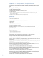
Appendix A – Using SSSU to configure the EVA presents a sample script that creates multiple Vdisks,
alternates path preferences between two controllers, and presents the Vdisks to vSphere servers.
This section outlines the following options for configuring an EVA array:
Using Command View EVA
Running Command View EVA within a VM
Using the HP Insight Control Storage Module for vCenter
Using Command View EVA
Command View EVA can manage an array using one of the following methods:
Server-based management (SBM) – Command View EVA is deployed on a standalone server that
has access to the EVA storage being managed.
If desired, you can run Command View EVA within a VM, allowing you to clone this VM and use it
as a template that can be quickly redeployed as needed, with minimal reconfiguration required.
When running Command View EVA in a VM, the following modes are supported:
– Virtualized SCSI mode – The Command View EVA instance can only view the active path to LUN
0 on a single controller. This mode is enabled by default when you install Command View EVA
9.2 or later.
– VMDirectPath mode – The Command View EVA instance bypasses the virtualization layer and
can directly manage the EVA storage. This mode is supported on Command View EVA 9.3 or
later.
For more information, refer to the VMware knowledge base article, “Configuring VMDirectPath
I/O for HP Command View EVA.”
Note
While this knowledge base article indicates that VMDirectPath mode is
experimental, HP and VMware have agreed to support this feature.
Array-based management (ABM) – For supported EVA models, Command View EVA can be
deployed on the array’s management module.
6
Running Command View EVA within a VM
Your ability to deploy Command View EVA within a VM may be impacted by the following:
EVA model
Command View EVA version being used
Availability of a host bus adapter (HBA) that can be dedicated to the VM
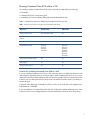
Table 1 compares the options for deploying Command View EVA in a VM.
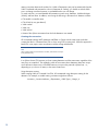
Table 1. Comparing requirements for Virtualized SCSI and VMDirectPath modes
Requirement
Virtualized SCSI
VMDirectPath
Minimum EVA firmware
XCS 09534000 or later
All
Minimum Command View EVA
software
9.2 or later
9.3 or later
Dedicated HBA required
No
Yes
Compatible EVA models
EVA8400,
EVA6400,
EVA4400,
EVA4400-S
EVA4100,
EVA6100,
EVA8100,
EVA8400,
EVA6400,
EVA4400,
EVA4400-S
Command View EVAPerf support
No
Yes
SSSU support
Yes
Yes
VMware vMotion support
Yes
No
Caveats for installing Command View EVA in a VM
If you are installing Command View EVA in a VM, take care where you deploy the VMware virtual
disk hosting the operating system on which you plan to install Command View EVA. If you were to
deploy this virtual disk on the same array that you intend to manage with the Command View EVA
instance, any issue that causes the EVA array to be inaccessible would also impact your ability to
identify this issue.
In general, when deploying Command View EVA in a VM, use a virtual disk on the vSphere host’s
local datastore, if available.
If you must deploy the Command View EVA VM on the SAN, then consider deploying two or more
instances on two or more storage systems to increase availability in the event of an array failure.
7
Best practices for deploying Command View EVA in a VM with VMDirectPath I/O
Deploy Command View EVA on the local datastore of the particular vSphere server.
If a SAN-based Command View EVA deployment is required, then deploy instances on multiple
arrays within the infrastructure to ensure the management interface remains available in the event
the array hosting the VM for the primary Command View EVA instance becomes inaccessible.
For information on configuring VMDirectPath for use with Command View EVA, refer to Appendix E –
Configuring VMDirectPath I/O for Command View EVA in a VM.
Using the Storage Module for vCenter
HP Insight Control Storage Module for vCenter is plug-in for vCenter Server that allows HP servers,
storage, and networking to be managed from a single pane of glass that is integrated into the
vSphere client.
Available at no cost from HP, the plug-in can be installed once for the entire vCenter environment
using a single, all-inclusive installer.
Key storage features of the plug-in include:
Monitoring the status and health of HP storage arrays
Providing detailed views of the relationships between the virtual and physical environment
Automated provisioning of datastores and VMs
– Adding, removing, and expanding datastores
– Creating VMs from templates on new datastores
– Using array-based snapshot and snap clone technologies to clone VMs
8
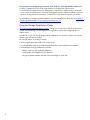
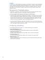
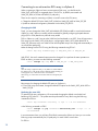
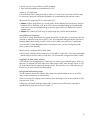
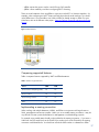
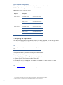
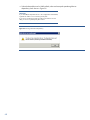
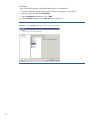
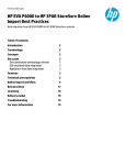
Figure 1 shows the overview screen for the HP Insight Control Storage Module for vCenter plug-in.
Figure 1. Typical overview screen for the vCenter plug-in, viewed via the HP Insight Software tab
The Storage Module for vCenter can enhance VMware functionality by providing detailed views of
the relationships between the virtual and physical environments. Understanding the physical
infrastructure helps you make better-informed decisions when you are designing, deploying,
maintaining, and troubleshooting a virtual environment.
The plug-in can provide detailed information about the mapping between a VM and the disks on
which its data resides. This information can be important – for example, to ensure that a production
database application is located within a particular array on RAID 1 storage that is being replicated to
a remote data center. This level of visibility previously required you to manually track mappings
between storage and virtual objects using large spreadsheets.
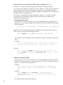
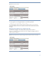
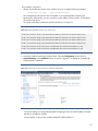
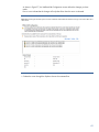
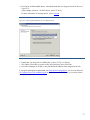
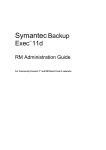
Figure 2 shows the mapping between a VM (ESX_VM01) and four volumes in an EVA array.
Figure 2. Mapping from the virtual to physical environment with the Storage Module for vCenter
9
The Storage Module for vCenter also provides automated provisioning for datastores and VMs. After
the storage administrator has configured the plug-in to support automated provisioning for specific
EVA disk groups, the VMware administrator can then perform automated storage provisioning
operations – quickly, without requiring the assistance of the storage administrator.
Best practice for mapping virtual objects to storage and for monitoring and
provisioning storage
Use the Storage Module for vCenter to save time and improve efficiency by mapping, monitoring,
provisioning, and troubleshooting EVA storage directly from vCenter.
For more information on the Storage Module for vCenter, refer to the HP Insight Control Storage
Module for vCenter User Guide.
Array hardware configuration and cabling
Best practices for EVA hardware configuration and cabling are well defined in the HP StorageWorks
6400/8400 Enterprise Virtual Array user guide and, thus, are not described in great detail in this
paper.
However, it is important to note that when configuring vSphere to access an EVA array, HP highly
recommends creating a redundant SAN environment by leveraging the following components:
Redundant controllers on the EVA array
Redundant Fibre Channel SANs
At a minimum, dual HBAs in each ESX host
10
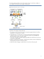
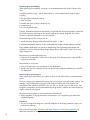
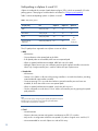
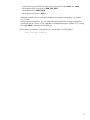
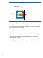
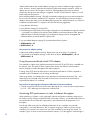
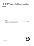
The resulting topology should be similar to that presented in Figure 3, which shows a vSphere 4.x
server attached to an EVA4400 array through a redundant fabric.
Figure 3. Highly-available EVA/vSphere 4.x SAN topology
The benefits of this topology include the following:
The topology provides increased fault tolerance, with protection against the failure of an HBA, a
single fabric, or a controller port or controller.
As described earlier, it is a best practice to access the Vdisk through the managing (optimal)
controller for read I/O. Thus, in the event of an HBA failure, failover occurs at the HBA-level,
allowing the Vdisk to remain on the same controller.
For this reason, HP highly recommends configuring each HBA port in the ESX server to access one
or more ports on each controller.
Similarly, a controller failure only triggers a controller failover and does not cause an HBA failover,
reducing system recovery time in the event of a failure.
A fabric failure does not trigger a controller failover or force the use of the proxy path.
11
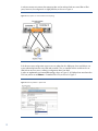
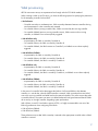
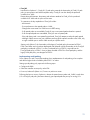
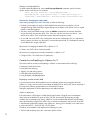
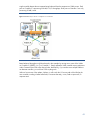
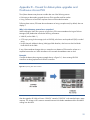
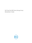
In a direct-connect environment, the same principles can be achieved with two more HBA or HBA
ports; however, the configuration is slightly different, as shown in Figure 4.
Figure 4. EVA/vSphere 4.x and 5.0 direct-connect topology
If the direct-connect configuration were to use two rather than four HBA ports, there would be a oneto-one relationship between every HBA and controller. Thus, a controller failover would result in an
HBA failover and vice versa, creating a configuration that is not ideal.
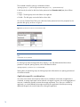
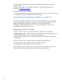
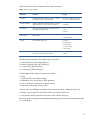
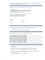
In order to implement the recommended topology shown in Figure 3, all vSphere hosts must have their
EVA host profiles set to VMware in Command View EVA, as shown in Figure 5.
Figure 5. EVA host profile for a vSphere host
12
Note
When configuring VMware Consolidated Backup (VCB) with an EVA array,
all vSphere hosts must be set to VMware. However, the VCB proxy host,
which is a Microsoft® Windows® server attached to the EVA, must be set
to Microsoft Windows (Windows Server 2003) or Microsoft Windows 2008
(Windows Server 2008).
Disk group provisioning
An EVA disk group is the largest storage object within the EVA storage virtualization scheme and is
made up of a minimum of eight physical disks (FC or Near-Line drives). Within a disk group, you can
create logical units of various sizes and RAID levels.
Note
An EVA RAID levels is referred to as VraidX.
The EVA array allows Vraid1, Vraid5, and Vraid6 logical units to coexist in
the same disk group on the same physical spindles.
When configuring an EVA disk group for vSphere 4.x and 5.0, you should keep in mind the
following important factors:
Formatted capacity
Sparing overhead and drive failure protection level
Application being virtualized
Storage optimization requirements
More information is provided on the following topics:
Formatted capacity
Sparing overhead and drive failure protection level
Application-specific considerations
Storage optimization
Formatted capacity
Although disk capacity is typically referred to in round, integer numbers, actual storage capacity in
an EVA is tracked in binary form; thus, the formatted capacity of a drive may be slightly smaller than
its nominal capacity. For example, a drive with a nominal capacity of 146 GB provides 136.73 GB
of formatted capacity, approximately 6.5% less.
Sparing overhead and drive failure protection level
Sparing overhead in an EVA array is defined as the amount of space that must be reserved to be able
to recover from physical disk failures within a disk group. Unlike other storage systems, which set
aside specific disks as spare drives, the EVA spreads the spare space4 across all the disks within a
group. The EVA sparing implementation eliminates the possibility of an assigned spare disk failing
when it is needed for recovery.
4
Also known as reconstruction space
13
The overhead created by sparing is calculated as follows:
"Sparing capacity = " ("Size of largest disk in disk group * 2" )" * (Protection level)"
In this formula, the value for disk drive failure protection level (Protection Level) may be as follows:
None
Single – The disk group survives the failure of a single disk
Double – The disk group survives the failure of two disks
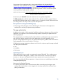
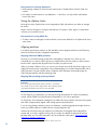
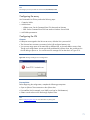
You can use Command View EVA to set a disk drive failure protection level in the properties for the
particular disk group, as shown in Figure 6.
Figure 6. Disk protection level as seen in Command View EVA
Note
Vraid0 Vdisks are not protected.
For a disk group where the largest disk drive capacity is 146 GB and double disk drive failure
protection is required, sparing capacity can be calculated as follows:
Sparing capacity = (136.73 * 2) * 2 = 546.92 GB
Sparing does not span disk groups; each disk group must be allocated its own sparing space based
on the above formula.
Application-specific considerations
One of the most common misconceptions about server virtualization is that when an application is
virtualized, its storage requirement can be reduced or changed. In practice, due to the aggregation of
resources, virtualization typically increases the storage requirement. Thus, when you virtualize an
application, you should maintain the storage required by this application while also provisioning
additional storage for the virtual infrastructure running the application.
14
Sizing storage for any application that is being virtualized begins with understanding the
characteristics of the workload. In the white paper, “Best Practices for the HP EVA Array using
VMware vCenter Site Recovery Manager,” HP describes how to determine the number of disks
needed to support a particular application. The following formula is used to calculate the spindle
count required for a random access workload:
Number of drives needed= ("Total IOPS* RAID penalty* Write%" )"+(Total IOPS* Read%)"
Raw performance of the disk drive
In this formula, the Total IOPS value and read/write ratio are application-dependent.
The RAID penalty value is defined as the number of I/Os to disk that result from a guest I/O due to
the particular Vraid level being used. For example, every I/O request to a Vraid1 Vdisk results in two
I/Os being issued in the array in order to provide data protection.
Best practice for sizing an EVA disk group
When sizing an EVA disk group, start by determining the characteristics of the application’s
workload, which will help you optimize array performance.
Storage optimization
In addition to the number of disks required to handle the performance characteristics of the particular
application, you must also account for the total storage capacity required by the applications and
VMs being deployed.
This storage capacity can be determined by simple arithmetic by adding the storage requirements for
each VM to the capacity required for the various applications. However, depending on your
particular storage optimization objective, the actual formatted capacity yielded can be lower than the
simple aggregation of the required number of EVA drives.
HP defines three storage optimization schemes, each of which is subject to specific storage overhead
and deployment considerations:
Cost
Availability
Performance
Optimizing for cost
When optimizing for cost, you goal is to minimize the cost per GB (or MB). Thus, it makes sense to
minimize the number of disk groups; in addition, since the cost per GB is lower as drive capacity
increases, it is best to use the largest disks of the same capacity within a particular disk group.
Even if you have disks with different capacities, it is better use them in a single disk group rather than
creating multiple disk groups.
Best practice for filling the EVA array
To optimize performance, fill the EVA with as many disks as possible using the largest, equalcapacity disks. Note that the use a few larger drives with many small drives is inefficient due to
sparing considerations.
15
Optimizing for availability
When optimizing for availability, your goal is to accommodate particular levels of failures in the
array.
Availability within the array – and its usable capacity – can be impacted by a range of factors,
including:
Disk group type (enhanced or basic)
Vdisk Vraid type
Number and variety of disks in the disk group
Protection levels
Use of array-based copies
Typically, the additional protection provided by using double disk drive failure protection at the disk
group-level cannot be justified given the capacity implications; indeed, single disk drive failure
protection is generally adequate for most environments.
Enhanced disk groups offer features such as:
Vraid6 protection, along with the traditional EVA Vraid0, 1, and 5
Additional metadata protection, which is associated with a further storage capacity overhead
Many database applications use Vraid1 for database log files to guarantee performance and
availability. However, while providing stronger data protection than Vraid5, Vraid1 has a much
higher storage cost.
Best practice for protecting the disk group
Single disk drive protection is sufficient for a disk group unless the mean time to repair (MTTR) is
longer than seven days.
Best practices for using Vraid
Only use Vraid6 when it is a requirement for your deployment.
Vraid5 comes at a lower storage-capacity cost and provides adequate redundancy for most ESX
4.x deployments.
Optimizing for performance
When optimizing for performance, your goal is to drive as much performance as possible from the
system.
However, configuring for optimal performance may have an impact on usable storage capacity. For
example, it may be desirable to segregate small random workloads with short response time
requirements from sequential workloads. In this use case, you should create two disk groups, even
though this configuration would create additional sparing capacity utilization and reserved sparing
capacity within each disk group.
Best practice for using disks of various performance characteristics
When using disks of varying performance characteristics, use a single disk group rather than
multiple disk groups.
Summary
The use of a single EVA disk group is typically adequate for all storage optimization types (cost,
performance, capacity).
Refer to the HP white paper, HP 4400/6400/8400 Enterprise Virtual Array configuration for
additional information on storage optimization.
16
Vdisk provisioning
All EVA active-active arrays are asymmetrical and comply with the SCSI ALUA standard.
When creating a Vdisk on an EVA array, you have the following options for specifying the preference
for the managing controller for that Vdisk:
No Preference
– Controller ownership is non-deterministic; Vdisk ownership alternates between controllers during
initial presentation or when controllers are restarted
– On controller failover (owning controller fails), Vdisks are owned by the surviving controller
– On controller failback (previous owning controller returns), Vdisks remain on the surviving
controller; no failback occurs unless explicitly triggered
Path A-Failover only
– At presentation, the Vdisk is owned by Controller A
– On controller failover, the Vdisk is owned by Controller B
– On controller failback, the Vdisk remains on Controller B; no failback occurs unless explicitly
triggered
Path A-Failover/failback
– At presentation, the Vdisk is owned by Controller A
– On controller failover, the Vdisk is owned by Controller B
– On controller failback, the Vdisk is owned by Controller A
Path B-Failover only
– At presentation, the Vdisk is owned by Controller B
– On controller failover, the Vdisk is owned by Controller A
– On controller failback, the Vdisk is owned by Controller A; no failback occurs unless explicitly
triggered
Path B-Failover/failback
– At presentation, the Vdisk is owned by Controller B
– On controller failover, the Vdisk is owned by Controller A
– On controller failback, the Vdisk is owned by Controller B
In the event of a controller failure that triggers the failover of all owned Vdisks to the alternate
controller, it is critical that, when the failed controller is restored, Vdisk ownerships that were failed
over to the surviving controller are failed back to the restored controller. This action ensures that, after
a controller failover, the system can return to its default balanced/configured state and that all Vdisks
do not end up on a single controller, degrading system performance.
With vSphere 4.x and 5.0 and earlier versions of ESX, it is highly recommended to use one of the
following preferences when configuring EVA Vdisks:
Path A-Failover/failback
Path B-Failover/failback
These preferences ensure that Vdisk ownership is restored to the appropriate controller when a failed
controller is restored.
17
Vdisks should be created with their controller failover/failback preference alternating between
Controller A and B.
The above recommendations provide additional benefits in a multi-pathing configuration, as
described in Configuring multi-pathing.
Best practice controller ownership
Controller ownership for EVA Vdisks should alternate between Controller A and Controller B, using
the Path-A-Failover/Failback or Path-B-Failover/Failback setting.
Implementing multi-pathing in vSphere 4.x and 5.0
A key task when configuring vSphere 4.x and 5.0 is to set up multi-pathing so as to optimize the
connectivity and operation of the EVA array. In addition, advanced tuning of HBAs, virtual SCSI
adapters and ESX advanced parameters can help you increase storage performance.
Multi-pathing is implemented differently in ESX 3.5 or earlier and vSphere 4.x and 5.0. Both
implementations are described in this section.
Multi-pathing in ESX 3.5 or earlier
In ESX 3.5 or earlier, VMware only supported the following path policies for multi-pathing:
Most Recently Used (MRU) – When the failed path is restored following a failback, MRU continues
to use the active I/O path, whether or not this is the preferred path
Fixed – When the failed path is restored following a failback, the Fixed policy fails back to the
preferred path
Path policies were not ALUA- compliant and thus presented the following challenges:
The storage system was not polled for controller ownership preferences
Optimal paths were not given higher priority in I/O queues
These shortcomings made it difficult to balance Vdisk access and the workload, since ESX 3.5 or
earlier would use a single I/O path (that is, the first path discovered to the Vdisk).
18
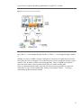
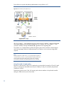
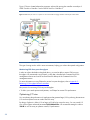
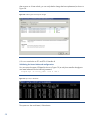
Figure 7 shows a typical multi-pathing implementation using ESX 3.5 or earlier.
Figure 7. EVA connectivity with ESX 3.5 or earlier
Here, Vdisks 1 – 4 are managed through Controller 1; Vdisks 5 – 7 are managed through Controller
2.
Whether you were to use MRU or Fixed I/O path policies, only the first I/O path discovered would
be used to queue I/Os, causing all I/Os from the ESX server to access a single port through a single
controller. Thus, all Vdisks would be accessed through HBA1, Fabric A, Path , and Controller 1;
other array ports and the second controller are left idle, to be used as standby paths.
There is no guarantee that the single, active path will utilize the owning controller for a particular
Vdisk (that is, it may not be the optimal path). Indeed, in this example, Vdisks 5 – 7 are being
accessed through the non-optimal controller.
19
Multi-pathing in vSphere 4.x and 5.0
vSphere 4 introduced the concept of path selection plug-ins (PSPs), which are essentially I/O multipathing options. These plug-ins are described in more detail in Configuring multi-pathing.
Table 2 outlines multi-pathing options in vSphere 4.x and 5.
Table 2. Multi-pathing options
I/O path policy
PSP
vSphere 4
vSphere 4.1
vSphere 5
MRU
VMW_PSP_MRU
Yes
Yes
Yes
Round Robin
VMW_PSP_RR
Yes
Yes
Yes
Fixed
VMW_PSP_FIXED
Yes
Yes
Fixed_AP (Array
Preference)
VMW_PSP_FIXED_AP
No
Yes
Yes
(Fixed =
Fixed_AP)
The I/O path policies supported since vSphere 4.x are as follows:
MRU
– ALUA-aware
– Gives preference to the optimal path to the Vdisk
– If all optimal paths are unavailable, MRU uses a non-optimal path
– When an optimal path becomes available, MRU fails over to this path
– Although vSphere servers may use a different port through the optimal controller to access the
Vdisk, only a single controller port is used for Vdisk access per vSphere server
Round robin
– ALUA-aware
– Queues I/O to Vdisks on all ports of the owning controllers in a round robin fashion, providing
instant bandwidth improvement over MRU
– Continues queuing I/O in a round robin fashion to optimal controller ports until none are
available, at which time it fails over to non-optimal paths
– When an optimal path becomes available, round robin fails over to it
– Can be configured to round robin I/O for a Vdisk to all controller ports by ignoring the optimal
path preference
Note
Using round robin policy and ignoring the optimal path preference may be
beneficial when you need to increase controller port bandwidth to
accommodate a write-intensive workload.
Fixed
– Not ALUA-aware
– Subject to the same intricate configuration considerations as ESX 3.5 or earlier
– May result in a configuration where the non-optimal I/O path to a logical unit is used for I/O
– Not recommended for use with vSphere 4.x and an EVA array
20
Fixed_AP
Introduced in vSphere 4.1, Fixed_AP I/O path policy extends the functionality of Fixed I/O path
policy to active-passive and ALUA-compliant arrays. Fixed_AP can also identify the preferred
controller for a Vdisk.
Despite being ALUA-aware, the primary path selection attribute for Fixed_AP is the preferred
controller for a Vdisk and not just its access state.
To summarize, the key capabilities of Fixed_AP include:
ALUA aware
Gives preference to the optimal path to a Vdisk
Changes the access state of a Vdisk but not its PREF setting
If all optimal paths are unavailable, Fixed_AP uses a non-optimal path and makes it optimal
If all non-optimal paths are unavailable, Fixed_AP uses an optimal path
If the path being used is non-optimal but preferred, Fixed_AP attempts to make this path optimal
Although vSphere servers may use a different port through the optimal controller to the Vdisk, only
a single controller port is used for Vdisk access per vSphere server
Starting with vSphere 5, the functionality of the legacy Fixed path policy that existed in ESX4.1,
ESX4.0 and older version has been deprecated and replaced with the functionality of the Fixed_AP
path policy introduced in ESX4.1. In short, Fixed path policy in ESX5.0 is equivalent to the
Fixed_AP path policy in ESX4.1 it has just been renamed in ESX5.0 to Fixed path policy and the
legacy Fixed path policy was dropped in ESX5.0.
Implementing multi-pathing
Since vSphere 4.x and 5 are ALUA-compliant, their implementation of multi-pathing is less complex
and delivers higher levels of reliability than ESX 3.5 or earlier.
Setting up multi-pathing only requires the following steps:
Configure the Vdisk
Select the controller access policy at the EVA
Power on/reboot all vSphere 4.x/5 servers or perform a rescan
Following the boot or rescan, vSphere 4.x detects the optimal access paths and, if MRU, round robin
I/O or Fixed_AP path policy has been selected, gives optimal paths the priority for issuing I/Os.
21
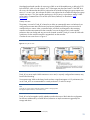
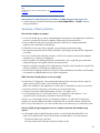
Figure 8 shows a typical multi-pathing implementation using vSphere 4.x/5.
Figure 8. EVA connectivity with vSphere 4.x/5
All I/Os to Vdisks 1 – 4 are routed through one or more ports on Controller 1 and through Paths
and/or , regardless of the HBA that originates the I/O. Similarly, all I/Os to Vdisks 5 – 7 are
routed to Controller 2 through Paths and/, regardless of the originating HBA.
The vSphere 4.x/5 implementation yields much higher system resource utilization and throughput
and, most importantly, delivers a balanced system out of the box, with no intricate configuration
required.
Note
From the perspective of Vdisk access, you can easily balance vSphere 4.x
with an EVA array. However, it may be desirable to capture performance
metrics at the EVA and assess data access to/from each controller to
ensure that the workload is truly balanced between the two controllers.
Using Fixed_AP I/O path policy
Because it is ALUA-aware, Fixed_AP I/O path policy can extend the functionality of Fixed I/O path
policy to active-passive and ALUA-aware arrays. In addition, Fixed_AP can identify the preferred
controller for a Vdisk.
Despite being ALUA aware, Fixed_AP’s primary path selection attribute is the preferred controller
setting of a Vdisk and not just its access state.
22
Note that the preferred controller for accessing a Vdisk in an ALUA-capable array is defined in SCSI
by the PREF bit, which is found in byte 0, bit 7 of the target port descriptor format5. If the PREF bit is
set to one, this indicates that the Vdisk is preferred to the controller the target port group request was
sent to; if it is set to zero, this indicates the Vdisk is not preferred to the controller the target port group
request was sent to. Thus, the controller preference in an EVA array is equivalent to setting a Vdisk
access path in Command View EVA to Path A/B-Failover/failback, as described in Vdisk
provisioning.
Primary use case
The primary use case for Fixed_AP is based on its ability to automatically return to a balanced, preconfigured environment after Vdisk access has become unbalanced following an event such as a
controller failure or restore. After a controller failure, all Vdisks would migrate to the remaining
controller and become optimized for that controller; however the logical unit’s initial controller
preference does not change and can point to the restored controller. Fixed_AP causes all Vdisks with
a preference for the restored controller to migrate back to that controller.
Consider the uses cases shown in Figure 9.
Figure 9. Fixed_AP use cases.
Fixed_AP can cause explicit Vdisk transitions to occur and, in a poorly configured environment, may
lead to Vdisk thrashing.
Since transitioning Vdisks under heavy loads can have a significant impact on I/O performance, the
use of Fixed_AP is not recommended for normal production I/O with EVA arrays.
Note
Fixed_AP can only be used to explicitly transition Vdisks on storage systems
that support explicit transitions, such as EVA arrays.
Fixed_AP can be leveraged to quickly rebalance preferred access to Vdisks after the configuration
has become unbalanced by controller failure/restoration or implicit transitions triggered by the
storage and others.
5
For more information, refer to SCSI Primary Commands (SPC).
23
Summary
In vSphere 4.x/5, ALUA compliance and support for round robin I/O path policy have eliminated the
intricate configuration required to implement multi-pathing in ESX 3.5 or earlier. These new features
also help provide much better balance than you could achieve with MRU; furthermore, round robin
policy allows I/Os to be queued to multiple controller ports on the EVA, helping create an instant
performance boost.
Best practices for I/O path policy selection
Round robin I/O path policy is the recommended setting for EVA asymmetric active-active arrays.
MRU is also suitable if round robin is undesirable in a particular environment.
Avoid using legacy Fixed I/O path policy with vSphere 4.x and EVA arrays.
In general, avoid using Fixed_AP I/O path policy with vSphere 4.x and EVA. However, this policy
can be leveraged to quickly rebalance Vdisks between controllers – for example, after a controller
has been restored following a failure. This use case can be employed with a single vSphere host
when the array is not under heavy load. Once the balanced state has been restored, you should
end the use of Fixed_AP and replace it with a recommended path policy.
Avoid using Fixed I/O path policy with vSphere 5 and EVA. However since Fixed I/O path policy
in ESX5 is the same as Fixed_AP in ESX4.1, the same use case considerations discussed above with
ESX4.1 also apply to Fixed I/O path policy in ESX5.
Configuring multi-pathing
The multi-pathing framework for vSphere 4.x/5 includes the following core components:
Native Multi-pathing Plug-in (NMP)
Also known as the NMM (Native Multi-pathing management extension module (MEM))
Storage Array Type Plug-in (SATP)
Also known as the SATM (Storage Array Type MEM); used in conjunction with the NMP
Path Selection Plug-in (PSP)
Also known as the PSM (Path Selection MEM); used in conjunction with a specific SATP
Multi-Pathing Plug-in (MPP)
Third-party implementation (which is outside the scope of this document) that takes the place of the
NMP/SATP/PSP combination
24
Figure 10 outlines key components of the multi-pathing stack.
Figure 10. vSphere 4.x and 5 multi-pathing stack
The key features of the multi-pathing plug-ins are as follows:
SATP
The SATP is an array-specific plug-in that handles specific operations such as device discovery, the
management of array-specific error codes, and failover.
For example, while storage arrays use a set of standard SCSI return codes to warn device drivers of
various failure modes, they also make use of vendor-specific codes to handle proprietary functions
and/or behavior. The SATP takes the appropriate action when these vendor–specific return codes
are received.
PSP
The PSP selects appropriate path to be used to queue I/O requests. PSP utilizes the following I/O
path selection policies:
– Fixed
– Fixed_AP6
– MRU
– Round robin
PSP settings are applied on a per-Vdisk basis; thus, within the same array, it is possible to have
some Vdisks using MRU while others are using the round robin policy.
6
Only supported in vSphere 4.1
25
NMP
The NMP ties together the functionality delivered by the SATP and PSP by handling many non-array
specific activities, including:
– Periodical path probing and monitoring
– Building the multi-pathing configuration
When a path failure occurs, the NMP communicates with the SATP and PSP and then takes the
appropriate action. For example, the NMP would update its list of available paths and
communicate with the PSP to determine how I/O should be re-routed based on the specified path
selection policy.
Displaying the SATP list
Although there is no way to monitor the NPM’s list of available paths through vCenter, you are able
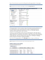
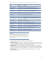
to display a list of available SATPs and their respective default PSPs (as shown in Table 3).
Use the following CLI command on the ESX console:
esxcli nmp satp list/grep EVA
Note
Currently, you cannot reconfigure the SATP rules table through vCenter.
26
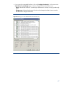
Table 3. vSphere 4.x and 5 SATP rules table, with entries that are relevant to EVA arrays denoted by an asterisk
SATP
Default PSP
Description
VMW_SATP_ALUA_CX
VMW_PSP_FIXED
Supports EMC CLARiiON CX arrays that use ALUA
VMW_SATP_SVC
VMW_PSP_FIXED
Supports IBM SAN Volume Controller (SVC) appliances
VMW_SATP_MSA
VMW_PSP_MRU
Supports HP Modular Smart Array (MSA) arrays
VMW_SATP_EQL
VMW_PSP_FIXED
Supports EqualLogic arrays
VMW_SATP_INV
VMW_PSP_FIXED
Supports the EMC Invista application
VMW_SATP_SYMM
VMW_PSP_FIXED
Supports EMC Symmetrix arrays
VMW_SATP_LSI Supports
VMW_PSP_MRU
Supports LSI and other arrays compatible with the SIS 6.10 in nonAVT mode
VMW_SATP_EVA*
VMW_PSP_FIXED
Supports HP EVA arrays
VMW_SATP_DEFAULT_AP*
VMW_PSP_MRU
Supports non-specific active/passive arrays
VMW_SATP_CX
VMW_PSP_MRU
Supports EMC CLARiiON CX arrays that do not use ALUA protocol
VMW_SATP_ALUA*
VMW_PSP_MRU
Supports non-specific arrays that use the ALUA protocol
VMW_SATP_DEFAULT_AA
VMW_PSP_FIXED
Supports non-specific active/active arrays
VMW_SATP_LOCAL
VMW_PSP_FIXED
Supports direct-attached devices
IMPORTANT
SATPs are global, whereas a PSP can either be global or set on a per-Vdisk
basis. Thus, a particular array can only use a specific SATP; however,
Vdisks on this array may be using multiple PSPs – for example, one Vdisk
can be set to round robin I/O path policy, while another Vdisk on the same
array is set to MRU.
As indicated in Table 3, the following SATPs are relevant to EVA arrays:
VMW_SATP_DEFAULT_AP – This SATP is used by active/passive EVA arrays. However, since such
arrays are not supported in vSphere 4.x and 5, you should not use this plug-in to enable a vSphere
4.x and 5 connection to an active/passive EVA for production purposes.
VMW_SATP_EVA – This SATP is intended for active/active EVA arrays that have the Target Port
Group Support (ALUA compliance) option turned off; however, all such arrays have TPGS turned on
by default. Since this option is not user-configurable, no current EVA arrays use VMW_SATP_EVA.
VMW_SATP_ALUA – This SATP is intended for any ALUA-compliant array; thus, it is used with
active-active EVA arrays.
27
Connecting to an active-active EVA array in vSphere 4
When connecting a vSphere 4 host to an active-active EVA array, you should use the
VMW_SATP_ALUA SATP as suggested above. This SATP is, by default, associated with
VMW_PSP_MRU, a PSP that uses MRU I/O path policy.
There are two steps for connecting a vSphere 4.x and 5 server to the EVA array:
Change the default PSP for the VMW_SATP_ALUA from VMW_PSP_MRU to VMW_PSP_RR
Update an advanced configuration parameter for the VMW_PSP_RR PSP
Changing the PSP
Firstly, you must change the VMW_SATP_ALUA default PSP/PSM from MRU to round robin because
vSphere 4.x and 5 does not currently provide a method for globally configuring the path selection
plug-in (PSP or PSM) based on a particular array model.
PSPs in vSphere 4.x and 5 are set at the Vdisk level and are based on an SATP. Since all active-active
EVA arrays use the VMW_SATP_ALUA plug-in, configuring the VMW_SATP_ALUA default PSP to
VMW_PSP_RR causes every new Vdisk from an ALUA-capable array to be configured automatically to
use round robin path policy.
Make the change via the ESX CLI using the following command using ESX 4.1:
esxcli nmp satp setdefaultpsp -P VMW_SATP_ALUA -S VMW_PSP_RR
With ESXi 5, the esxcli command name space has changed. So to perform the same operation on
ESXi5 as above, you must issue the following command:
esxcli storage nmp satp set –P VMW_PSP_RR –s VMW_SATP_ALUA
Note
When this setting is applied on the fly, it only affects new Vdisks added to
the vSphere host. In order for the change to affect all Vdisks (including preexisting logical units, a reboot of the host is recommended.
Alternatively, you could unclaim and reclaim all devices managed by the
NMP.
Best practice for changing the default PSP option in vSphere 4.x
For an EVA array environment, change the default PSP option for the VMW_SATP_ALUA SATP to
VMW_PSP_RR.
Updating the new PSP
To optimize EVA array performance, HP recommends changing the default round robin load
balancing IOPS value to 1. This update must be performed for every Vdisk using the following
command on ESX4.x:
esxcli nmp roundrobin setconfig -t iops -I 1 -d naa.xxxxxxxxx
or the following command on ESXi5
esxcli storage nmp psp roundrobin deviceconfig set -t iops -I 1 -d
naa.xxxxxxxxx
In an environment where you only have EVA Vdisks connected to vSphere 4.x hosts you can use the
following script to automatically set I/O path policy for each Vdisk to round robin:
For ESX4.x
28
for i in `esxcli nmp device list | grep naa.600` ; do esxcli nmp
roundrobin setconfig -t iops –I 1 -d $i; done
For ESXi5
for i in `esxcli storage nmp device list | grep naa.600` ; do
esxcli storage nmp psp roundrobin deviceconfig set -t iops –I 1 device $i; done
For environments with multiple array models, merely change grep naa.600 so that it matches the
pattern to devices on the desired arrays only.
29
Connecting to an active-active EVA array in vSphere 4.1/5
In vSphere 4.1, VMware introduced more granular SATP and PSP configuration options.
As in vSphere 4, each SATP has a default PSP. However, vSphere 4.1/5 also gives you the ability to
configure a particular PSP based on the storage array model. This is a significant improvement,
allowing multiple arrays to use the same SATP but, by default, utilize different PSPs, which provides a
tremendous savings in configuration time.
As in vSphere 4, the default PSP for VMW_SATP_ALUA in vSphere 4.1/5 is VMW_PSP_MRU.
Configuring the recommended PSP, VMW_PSP_RR, can be achieved in two different ways,
depending on the deployment type:
Same I/O path policy settings
If the vSphere 4.1 cluster is connected to one or more ALUA-capable arrays using the same I/O
path policy, you can change the default PSP for the VMW_SATP_ALUA to VMW_PSP_RR using the
following command:
esxcli nmp satp setdefaultpsp --satp VMW_SATP_ALUA --psp VMW_PSP_RR
With ESXi 5, the esxcli command name space has changed. So to perform the same operation on
ESXi5 as above, you must issue the following command:
esxcli storage nmp satp set –P VMW_PSP_RR –s VMW_SATP_ALUA
You would then run the configuration script to set each device type to its preferred I/O path policy
option:
For ESX4.1
for i in `esxcli nmp device list | grep naa.600` ; do esxcli nmp
roundrobin setconfig --type “iops” --iops=1--device $i; done
For ESXi5
for i in `esxcli storage nmp device list | grep naa.600` ; do
esxcli storage nmp roundrobin deviceconfig set -t iops –I 1 -device
$i; done
Different I/O path policy settings
If the vSphere 4.1/5 cluster is connected to two or more ALUA capable arrays that each requires
different I/O path policy settings, you can leverage the new SATP and PSP configuration options in
vSphere 4.1/5 via the following command line:
For ESX4.1
esxcli nmp satp addrule –s VMW_SATP_DEFAULT_AA –P VMW_PSP_RR –o
iops –O iops=1 –c tpgs_on –V HP –M HSV300 –e “My custom EVA4400
rule"
For ESXi5:
esxcli storage nmp satp rule add –s VMW_SATP_DEFAULT_AA –P
VMW_PSP_RR –o iops –O iops=1 –c tpgs_on –V HP –M HSV300 –e “My
custom EVA4400 rule"
This single command line achieves the following:
30
– Create a new rule in the SATP rule table for the array specified with –vendor and –model
– Set the default SATP for this array to VMW_SATP_ALUA
– Set the default PSP to VMW_PSP_RR
– Set the round robin option to IOPS=1
Repeat this command line for each ALUA-compliant array model to be shared by your vSphere
4.1/5 cluster.
With this single command line, you can achieve the same results as the two-stage configuration
process required for vSphere 4. Thus, regardless of the deployment type in vSphere 4.1/5, running
this single addrule command is far more efficient.
Use the following command to verify that the new rule has been successfully added:
esxcli nmp satp listrules
31
Deleting a manually-added rule
To delete a manually-added rule, use the esxcli nmp satp deleterule command; specify the same
options used to create the rule. For example:
esxcli nmp satp deleterule --satp="VMW_SATP_ALUA" -psp="VMW_PSP_RR" --psp-option="iops=1" --claim-option="tpgs_on" -vendor="HP" --model="HSV210" --description="My custom HSV210 rule"
Caveats for changing the rules table
When making changes to the SATP rules table, consider the following:
On-the-fly rule changes only apply to Vdisks added to the particular array after the rule was
changed. Existing Vdisks retain their original settings until a vSphere server reboot occurs or a path
reclaim is manually triggered.
The array vendor and models strings used in the addrule command line must exactly match the
strings returned by the particular array. Thus, if the new rule does not claim your devices – even
after a server reboot – then verify that the vendor and model strings are correct.
As you add rules to the SATP rules, tracking them can become cumbersome; thus, it is important to
always create a rule with a very descriptive, consistent description field. This facilitates the retrieval
of user-added rules using a simple filter.
Best practice for changing the default PSP in vSphere 4.1/5
Create a new SATP rule for each array model.
Best practice for configuring round robin parameters in vSphere 4.x/5
Configure IOPS=1 for round robin I/O path policy.
Caveats for multi-pathing in vSphere 4.x/5
This section outlines caveats for multi-pathing in vSphere 4.x associated with the following:
Deploying a multi-vendor SAN
Using Microsoft clustering
Toggling I/O path policy options
Using data replication (DR) groups
Using third-party multi-pathing plug-ins
Deploying a multi-vendor SAN
In an environment where ALUA-capable arrays from multiple vendors are connected to the same
vSphere 4.x cluster, exercise caution when setting the default PSP for VMW_SATP_ALUA, especially if
the arrays have different recommendations for the default PSP option.
Setting the appropriate PSP differs depending on the deployment type.
vSphere 4 deployment
If the total number of EVA Vdisks is smaller than the total number of logical units from third-party
arrays, then set the default PSP option to VMW_PSP_RR, assuming that the third-party storage
vendor(s) also recommend(s) this setting. Otherwise, use the recommended default for the third-party
arrays and manually configure EVA Vdisks. Thus, to minimize configuration time, the bulk of the task
is automatically performed by default using vSphere 4.x, leaving you to manually run a simple script
to set the desired PSP – VMW_PSP_RR – for EVA Vdisks.
The above recommendation only applies to the following use case:
The EVA and third-party arrays are in the same vSphere 4 SAN
32
Arrays from two or more vendors are ALUA-compliant
There are different default recommendations for PSPs
vSphere 4.1/5 deployment
If the multi-vendor SAN is being shared by a vSphere 4.1 cluster, then create a new SATP rule entry
for each array, setting the configuration parameters as recommended by the particular vendor.
Best practice for configuring PSP in a multi-vendor SAN
vSphere 4: When using vSphere 4 in a multi-vendor, ALUA-compliant SAN environment, configure
the default PSP for the VMW_SATP_ALUA SATP to the recommended setting for the predominant
array type or to the recommended setting for the array type with the most Vdisks provisioned for
vSphere access.
vSphere 4.1: Create a SATP rule entry for each storage array with the desired attributes.
Using Microsoft clustering
At the time of writing, VMware does not support round robin I/O path policy in conjunction with VMs
clustered via Microsoft Cluster Server (MSCS). Thus, HP recommends setting all VMware Raw Device
Mapping (RDM) Vdisks used by an MSCS cluster to utilize MRU as the preferred I/O path policy.
Since most MSCS cluster deployments utilize several logical units, you should configure the path
policy for these Vdisks manually.
Best practice for configuring MSCS cluster Vdisks
MSCS cluster Vdisks should be configured to use the MRU I/O path policy. Since the recommended
default setting for all EVA Vdisks is round robin, you must manually configure these Vdisks to MRU.
Toggling I/O path policy options
Once configured, avoid toggling the I/O path policy for Vdisks using round robin policy. When I/O
path policy is changed from round robin to any other (fixed or MRU), either through vCenter or a CLI,
all round robin advanced configuration settings are lost. The next time you set round robin policy for
that device, you must manually reset these settings.
Using Data Replication groups
The HP Continuous Access EVA software allows data to be replicated between two or more EVA
arrays, either synchronously or asynchronously.
Continuous Access EVA supports various interconnection technologies such as Fibre Channel or Fibre
Channel over IP (FCIP).
A DR group is the largest replication object within Continuous Access EVA and is comprised of
replicated Vdisks (copy sets), as shown in Figure 11.
33
Figure 11. Relationship between Vdisks and the DR group
Disk Group
DR Group
Vdisk
Just like a Vdisk, a DR group is managed through one controller or the other; in turn, this controller
must manage all Vdisks within the particular DR group. Thus, when a Vdisk is added to an existing DR
group, its optimal controller is the one currently managing the DR group.
Since the inheritance of controllers can impact the overall balance of Vdisk access, you should ensure
that DR groups are spread across both controllers.
Best practice for managing controllers for DR groups
Ensure that DR groups are spread between the controllers so as to maintain an adequate balance.
Using MPPs
vSphere 4.x allows third-party storage vendors to develop proprietary PSP, SATP, or MPP plug-ins (or
MEMs), some of which are under development or are already available in the form of technology
previews.
These third-party MEMs will be offered to customers at an incremental license cost and will also
require enterprise VMware licensing.
The EVA array was designed to provide optimal performance and functionality using native VMware
multi-pathing plug-ins, saving you the extra work and expense associated with proprietary plug-ins.
When used, configured and tuned appropriately, native plug-ins can significantly reduce
configuration time and provide enhanced performance in most environments at zero incremental cost,
while keeping the solution simplified.
34
Upgrading EVA microcode
An online upgrade of EVA microcode is supported with vSphere 4.x.
When performing such upgrades it is critical to follow the general EVA Online Firmware Upgrade
(OLFU) guidelines defined in the OLFU best practices guide7.
From a vSphere 4.x perspective, VMs using RDM Vdisks are more susceptible to issues resulting from
an OLFU. It is important to ensure that the SCSI disk timeout for all VMs is set to a minimum of 60
seconds, higher (60 – 90 seconds) in a larger environment.
Guidelines are provided for setting the SCSI disk timeout for Microsoft Windows and Linux VMs.
Setting the timeout for Windows VM
For a VM running Windows Server 20038 or earlier, change the value of the
HKEY_LOCAL_MACHINE/SYSTEM/CurrentControlSet/Services/Disk/TimeoutValue registry setting to
3c (that is, 60 expressed in hexadecimal form).
A reboot is required for this change to take effect.
Setting the timeout for Linux VMs
Use one of the following commands to verify that the SCSI disk timeout has been set to a minimum of
60 seconds:
cat /sys/bus/scsi/devices/W:X:Y:Z/timeout
or
cat /sys/block/sdX/device/timeout
If required, set the value to 60 using one of the following commands:
echo 60 > /sys/bus/scsi/devices/W:X:Y:Z
or
echo 60 | cat /sys/block/sdX/device/timeout
where W:X:Y:Z or sdX is the desired device.
No reboot is required for these changes to take effect.
Overview of vSphere 4.x storage
vSphere 4.x supports VMware Virtual Machine File System (VMFS), RDM, and Network File System
(NFS) datastores, each of which can deliver benefits in a particular environment. This section provides
information for the following topics:
Using VMFS
Using RDM
Comparing supported features
Implementing a naming convention
Sizing the vSphere cluster
Aligning partitions
7
8
See
http://h20000.www2.hp.com/bizsupport/TechSupport/Product.jsp?lang=en&cc=us&taskId=101&contentType=SupportManual&docIndexId=
64255&prodTypeId=12169&prodCatId=304617
In Windows Server 2008, the SCSI timeout defaults to 60 seconds.
35
Using VMFS
VMFS is a high-performance cluster file system designed to eliminate single points of failure, while
balancing storage resources. This file system allows multiple vSphere 4.x hosts to concurrently access
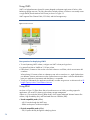
a single VMDK (Virtual Machine Disk Format), as shown in Figure 12.
VMFS supports Fibre Channel SAN, iSCSI SAN, and NAS storage arrays.
Figure 12. VMFS datastore
Best practices for deploying VMFS
To avoid spanning VMFS volumes, configure one VMFS volume per logical unit.
In general limit VMs or VMDKs to 15-20 per volume.
Either place I/O-intensive VMs on their own SAN volumes or use RDMs, which can minimize disk
contention.
When placing I/O-intensive VMs on a datastore, start with no more than six – eight vSphere hosts
per datastore. Monitor performance on the vSphere hosts to ensure there is sufficient bandwidth to
meet your application requirements and that latency is acceptable.
To help you understand your application workloads, consider using services or software such as HP
Insight Capacity Advisor Consolidation Software.
Using RDM
As shown in Figure 13, RDM allows VMs to have direct access to Vdisks, providing support for
applications such as MSCS clustering or third-party storage management.
vSphere 4.x/5 provides the following RDM modes, which support advanced VMware features like
vMotion, High Availability (HA), and Distributed Resource Scheduler (DRS):
Virtual compatibility mode (vRDM):
– All I/O travels through the VMFS layer
– RDMs can be part of a VMware snapshot
Physical compatibility mode (pRDM):
– All I/O passes directly through the underlying device
36
– pRDM requires the guest to use the virtual LSI Logic SAS controller
– pRDM is most commonly used when configuring MSCS clustering
There are some limitations when using RDM in conjunction with MSCS or VMware snapshots – for
example, when configuring an MSCS cluster with both physical and virtual machines. You should
utilize pRDM since it is not possible to use Vdisks or RDMs as shared storage in vRDM. For more
information, refer to the VMware white paper, “Setup for Failover Clustering and Microsoft Cluster
Service.”
Figure 13. RDM datastore
Comparing supported features
Table 4 compares features supported by VMFS and RDM datastores.
Table 4. Datastore supported features
Feature
VMFS
RDM
VMware Native Multi-pathing (NMP)
Yes
Yes
VMware vMotion
Yes
Yes
VMware Storage vMotion
Yes
Yes
MSCS
No
Yes
Implementing a naming convention
When working with multiple datastores, VMDKs, and RDMs in conjunction with large clusters or
SANs, management can become complex. Unless you use a suitable naming convention, it may be
very difficult to locate a particular datastore for management or troubleshooting purposes.
For example, array model names should not be included in the naming convention – if you move a
Vdisk from one EVA model (such as the EVA8100) to another (such as the EVA4400), the naming
convention would break down. You should not include the Vdisk number in a datastore or RDM
37
naming convention because the number for a Vdisk in Datacenter A may not be maintained when the
Vdisk is replicated and presented to a host in Datacenter B. Similarly, you should not include Vdisk
size in a naming convention because it is probable that this size will change.
To avoid confusion, you need detailed documentation on each array, datastore, Worldwide Name
(WWN), and host name. In addition, avoid using the following in the name for a datastore or RDM:
EVA model or controller name
EVA WWN (or any part thereof)
Vdisk number
Vdisk size
Vdisk WWN
Name of the vSphere servename from which the datastore was created
Creating the convention
HP recommends naming VMFS datastores and RDMs in vCenter with the same name used when
creating the Vdisk in Command View EVA or when using SSSU scripting tools. While this approach is
beneficial, it may require some coordination with the storage administrator.
Note
When creating Vdisks in Command View or SSSU, Vdisk names are unique
to the particular array.
In a vSphere cluster, ESX prevents you from creating datastores with the same name, regardless of the
array they are created on. This capability yields an environment where datastore names are unique
across the entire infrastructure, while RDM names are unique to the particular vSphere host – or,
depending on your choice of names, to the entire infrastructure.
Using descriptive naming
When creating Vdisks in Command View EVA, HP recommends using descriptive naming for the
datastore. For example, a suitable naming convention might be as follows:
<Location>_<Location Attribute>_<Department>_<Vdisk Type>_<Usage>_#
38
Table 5 outlines the various components of this naming convention.
Table 5. Sample naming convention
Component
Description
Example
<Location>
Geographical location of the team, group or division
for which the storage is being allocated
The location could be a city, state,
country, or a combination thereof.
<Location Attribute>
Specific attribute of the particular location, such as an
office building floor or the scope of the department
Building R5
Job function of the team, group or division for which
the storage is being allocated
IT
<Department>
Third floor
Sales
Finance
<Vdisk Type>
Type of Vdisk
RDM
VMFS (datastore)
<Usage>
How the Vdisk will be used
VM boot
Exchange logs
Exchange data
Oracle_archLogs
Oracle_data
<#>
Provides enumeration in the event that multiple disks
with the same name should be needed
1
0002
The following are examples of this sample naming convention:
Houston_Enterprise_Sales_VMFS_VMBoot_1
Houston_Enterprise_Sales_VMFS_VMBoot_2
LA_Corporate_IT_RDM_ExchLogs_1
LA_Corporate_IT_RDM_ExchLogs_2
The advantages of this naming convention are as follows:
Simple
Synchronizes EVA and vSphere naming
Independent of any unique array or Vdisk properties
Does not break due to replication or Storage vMotion
Uniqueness automatically ensured by EVA
However, there are challenges associated with the naming convention, including the following:
Inability to quickly match the array Vdisk number only using the Vdisk name
Cross-reference matrix required for information such as Vdisk ID and array
Both of the above challenges can be addressed by deploying the HP Insight Control Storage Module
for vCenter plug-in.
39
Best practice for naming datastores
When naming a datastore, utilize the same name used in Command View when the Vdisk was
created
Use simple, consistent names for your datastores – in the future, you may need to add vSphere
hosts to the cluster
Sizing the vSphere cluster
Knowing how many vSphere hosts can be supported per Vdisk will enhance your ability to manage
the cluster9.
Monitor resource utilization to recognize VMs that are I/O-intensive. Often, high I/O requirements
will lower your overall host count.
Best practice for using Vdisk IDs
To make it easier to manage the cluster and SAN, use the same Vdisk ID for all vSphere hosts in the
same cluster.
Aligning partitions
In a vSphere environment, partitions on VM data disks must be aligned with disks on the EVA array;
however, the EVA array has no alignment requirements.
Aligning Vdisk and VMFS partitions
The array is a virtualized storage system that is managed by Command View. When you use
Command View to create a Vdisk to present to a supported host, the host mode you specify ensures
that the Vdisk is appropriately aligned for the file system you plan to mount.
When you present a Vdisk to a host, you can use your favorite secure shell (ssh) client to login to your
vSphere host and view the configuration of the presented Vdisk; you can then format the Vdisk with a
VMFS filesystem. Using the vSphere client to create the VMFS filesystem automatically aligns the
VMFS filesystem partition with the underlying Vdisk.
Aligning VM operating system partitions
IMPORTANT
If you are using Microsoft Windows Vista®, Windows 7, or Windows
Server 2008, you do not need to align partitions. These operating systems
correctly align the partition at the time you create the VMDK.
At some stage of your deployment, you may need to align the partitions for certain VM operating
systems with the VMDK to avoid performance degradation in your VM or application.
For EVA arrays, HP recommends creating all your VMDK files via the vSphere client and verifying that
each Vdisk is appropriately aligned; other storage systems may be different.
If you are using Storage vMotion to move your datastores, consult the appropriate storage vendor to
ensure your VMFS partitions or VMDK files are correctly aligned to disk.
VMware has carried out testing to compare I/O performance with aligned and non-aligned file
systems and, as a result, suggests working with your vendor to establish the appropriate starting
boundary block size. For more information, refer to the VMware white paper, “Performance Best
Practices for VMware vSphere 4.0.”
The maximum number of Vdisks that can be connected to a vSphere cluster is 256.
9
40
Best practices for aligning the file system
No alignment is required with Windows Vista, Windows 7, or Windows Server 2008.
Use the vSphere client when creating your datastore, which correctly aligns the file system.
Verify that VMDKs used by the guest operating system are correctly aligned.
Enhancing storage performance
A range of vSphere 4.x/5 features and tuning options provide opportunities for enhancing storage
performance. This section provides information on the following topics:
Optimizing queue depth
Using adaptive queuing
Using the paravirtualized virtual SCSI driver
Monitoring EVA performance in order to balance throughput
Optimizing I/O size
Optimizing queue depth
Queue depth is a function of how quickly processes are loaded into the queue and how fast the
queue is emptied between the HBA and a Vdisk.
Tuning the Vdisk queue depth is often regarded as a requirement in a vSphere environment that uses
SAN storage. Indeed, in some deployments, tuning the queue may help to enhance performance;
however, injudicious tuning can result in increased latency. HP suggests that, if your storage system is
properly configured and balanced, default queue depth values may be ideal. The best approach is to
analyze the entire environment, not just a single vSphere host.
Adjusting the queue depth requires you to determine how many commands the HBA can accept and
process for a given logical unit. Thus, as a best practice when adjusting the HBA queue depth, you
should adjust the vSphere Disk.Sched.NumReqOutstanding setting for each vSphere host. The simplest
way is to use the vSphere client and login to vCenter to make the necessary adjustments.
For more information on changing the HBA queue depth with vSphere 4.x, refer to the VMware
guide, “Fibre Channel SAN Configuration Guide.”
Best practice for adjusting the queue depth
When increasing the HBA queue depth, also increase the vSphere Disk.Sched.NumReqOutstanding
setting.
Using adaptive queuing
ESX 3.5 and vSphere 4.x/5 provide an adaptive queue depth algorithm that can dynamically adjust
the logical unit (LU) queue depth in the VMkernel I/O stack when congestion is reported by the
storage system in the form of QUEUE FULL or DEVICE BUSY status.
Dynamically adjusting the LU queue depth allows the VMkernel to throttle back I/O requests sent to
the particular LU, thus reducing I/O congestion in the storage system.
Adaptive queuing is controlled by the following advanced parameters:
QFullSampleSize: Controls how quickly the VMkernel should reduce the queue depth for the LU
returning DEVICE BUSY/QUEUE FULL status; by default, QFullSampleSize is set to 0, which disables
adaptive queuing
QFullThreshold: Controls how quickly the queue depth should be restored once congestion has been
addressed
41
vSphere administrators often enable adaptive queuing as a means to address storage congestion
issues. However, while this approach can temporarily help reduce storage congestion, it does not
address the root cause of the congestion. Moreover, although adaptive queuing can enhance
performance during times when storage is congested, overall I/O performance is superior in a welltuned, balanced configuration.
Before enabling adaptive queuing, HP highly recommends examining your environment to determine
the root cause of transient or permanent I/O congestion. For well-understood, transient conditions,
adaptive queuing may help you accommodate these transients at a small performance cost. However,
to address more permanent I/O congestion, HP offers the following suggestions:
Using VMware disk shares
Using VMware Storage IO Control (SIOC)
Re-evaluating the overall ability of the storage configuration to accommodate the required workload
– for example, non-vSphere hosts may have been added to a well-tuned, balanced SAN, placing
additional stress on the shared storage; such configuration changes must be investigated and
addressed before you throttle back the vSphere hosts
If you must enable adaptive queuing, HP recommends the following values:
QFullSampleSize = 32
QFullThreshold = 8
Best practices for adaptive queuing
Rather than enabling adaptive queuing, determine the root cause of the I/O congestion
If you decide to use adaptive queuing, set the values as follows: QFullSampleSize = 32 and
QFullThreshold = 8
Using the paravirtualized virtual SCSI adapter
First available in vSphere 4 the VMware paravirtualized virtual SCSI (pvSCSI) driver is installed with
the VMware Tools. This guest OS driver communicates directly with VMware Virtual Machine
Monitor, helping to increase throughput while reducing latency.
In testing, the pvSCSI driver has been shown to increase the performance of Vdisks compared to
standard virtual SCSI adapters such as LSILogic and BusLogic.
When using Iometer, for example, there was a performance improvement of between 10% – 40%,
depending on the workload used. The tested I/O block sizes were 4 KB, 8 KB, and 64 KB for
sequential and random I/O workloads.
Best practices for improving the performance of VMs with I/O-intensive workloads
Consider using the pvSCSI driver with the VM’s data logical units, which can enhance performance
by 10% – 40%, depending on the particular workload used.
Monitoring EVA performance in order to balance throughput
ALUA compliance in vSphere 4.x has significantly reduced configuration complexity and given you
the ability to quickly configure a balanced Vdisk environment. However, you should monitor EVA host
port performance to ensure that this configuration is also balanced from the perspective of I/O
throughput.
Even though Vdisk access may be well-balanced between the two controllers in a particular
configuration, it is possible that most or all I/O requests are going to Vdisks on just one of these
controllers. In this scenario, the resources of one of the controllers are not being fully utilized. For
example, Figure 14 shows an environment where the majority of I/O throughput is routed through a
42
single controller despite the environment being balanced from the perspective of Vdisk access. Each
port on Controller 2 is processing 300 MB/s of I/O throughput, while ports on Controller 1 are only
processing 20 MB/s each.
Figure 14. Unbalanced I/O access in a vSphere 4.x environment
Better balanced throughput could be achieved in this example by moving one or more of the Vdisks
on Controller 2 (VDISK5, 6 or 7) to Controller 1. Simply update the Vdisk controller access preference
within Command View EVA to the desired value; alternatively, if you need to move multiple Vdisks to
an alternate controller, you could use SSSU scripting tools.
Within a few minutes of the update, vSphere 4.x will switch the I/O access path of the Vdisk to the
new controller, resulting in better balanced I/O accesses that may, in turn, lead to improved I/O
response times.
43
Figure 15 shows a better-balanced environment, achieved by moving the controller ownerships of
VDISK 5 and 6 to Controller 1 and of VDISK1 and 2 to Controller 2.
Figure 15. Balanced I/O access in a vSphere 4.x environment after changing controller ownership for certain Vdisks
This type of tuning can be useful in most environments, helping you achieve the optimal configuration.
Monitoring EVA host port throughput
In order to achieve the balance described above, you must be able to monitor EVA host port
throughput. HP recommends using EVAperf, a utility that is bundled with Command View EVA
management software and can be accessed from the desktop of the Command View EVA
management station.
For more information on using EVAperf to monitor host port throughput, refer to Appendix C –
Balancing I/O throughput between controllers.
Best practice for monitoring EVA host port throughput
To allow you to make proactive adjustments, use EVAperf to monitor EVA performance.
Optimizing I/O size
You can enhance the performance of applications that generate large I/Os by reducing the maximum
I/O size that vSphere hosts can send to the EVA array.
By design, vSphere 4.x allows I/Os as large as 32 MB to be sent to the array. You can control I/O
size via the vSphere advanced parameter Disk.DiskMaxIOSize. HP recommends setting this value to
128 KB for an EVA array to optimize overall I/O performance.
44
Note
VMware makes a similar recommendation in their knowledge base article
1003469.
Best practice for improving the performance of VMs that generate large I/Os
Consider setting the vSphere advanced parameter Disk.DiskMaxIOSize to 128 KB to enhance
storage performance.
Summary of best practices
How can I best configure my storage?
To size an EVA disk group, start by understanding the characteristics of the application workload to
ensure the virtualized environment is capable of delivering sufficient performance.
Using a single EVA disk group is typically sufficient to satisfy all your storage optimization
objectives (cost, performance, and capacity).
Fill the EVA with as many disks as possible, using the largest, equal-capacity disks.
The single-drive protection level should be sufficient for your disk group unless MTTR is longer than
seven days.
Do not use Vraid6 unless absolutely necessary. Vraid5 is less expensive and provides adequate
redundancy for a vSphere 4.x deployment.
When using disks with differing performance characteristics, use a single disk group rather than
multiple disk groups, having disks with the same characteristics.
Alternate controller ownership for EVA Vdisks between Controller A and Controller B using the PathA-Failover/Failback or Path-B-Failover/Failback setting.
Ensure that the managing controllers for DR groups are spread between Controller A and Controller
B to maintain an adequate balance in the system configuration.
Which is the best I/O path policy to use for my storage?
Round robin I/O path policy is the recommended setting for EVA active-active arrays except for
Vdisks used by an MSCS cluster, which should be set to MRU.
MRU is also suitable for other applications if round robin is undesirable in a specific environment.
Avoid using Fixed I/O path policy with vSphere 4.x/5 and an EVA array.
Configure round robin advanced parameters to IOPS=1 for vSphere 4.x/5.
For normal production I/O, avoid using Fixed_AP I/O path policy with vSphere 4.1 or its
equivalent Fixed I/O path policy with vSphere 5 and an EVA array.
However, you can leverage Fixed_AP I/O path policy (vSphere 4.1) and Fixed I/O path policy
(vSphere 5) to quickly rebalance the Vdisk configuration after a controller has been restored from
failure. Use just one vSphere 4.1/5 server from the cluster; ensure the array is not under heavy load.
How do I simplify storage management, even in a complex environment with multiple storage
systems?
In multi-vendor, ALUA-compliant SAN environment, you should select the default PSP for the
VMW_SATP_ALUA based on the PSP that has been recommended for one of the following:
– The most prevalent array in the SAN
– The array with the most Vdisks provisioned for vSphere access
45
In an exclusively EVA environment, change the default PSP option for VMW_SATP_ALUA to
VMW_PSP_RR.
Round robin I/O path policy is recommended for EVA active-active arrays. MRU is also suitable if
round robin is not desired in a particular environment.
Configure MSCS cluster Vdisks to use MRU I/O path policy. Since the recommended default setting
for all EVA Vdisks is round robin, you must manually configure MSCS Vdisks to MRU.
Alternate the controller ownership of EVA Vdisks between Controller A and Controller B by
configuring the Path-A-Failover/Failback or Path-B-Failover/Failback setting.
With vSphere 4.1, create a new SATP rule for each storage system.
Use the same Vdisk ID for all vSphere servers in the same cluster.
Use a simplified name for your datastores and be consistent, thus accommodating vSphere hosts
you may later add to the cluster.
To properly align the filesystem, use the vSphere client when creating a datastore.
When naming a datastore, use the same name you selected in Command View EVA when creating
the logical unit/Vdisk.
Utilize HP Insight Control Storage Module for vCenter to save time and improve efficiency by
mapping, monitoring, provisioning, and troubleshooting EVA storage directly from vCenter.
How can I best monitor and tune the EVA array in order to optimize performance?
If increasing the queue depth at the HBA level, also increase the value of the vSphere 4.x advanced
parameter Disk.SchedNumReqOutstanding.
When using VMs with I/O-intensive workloads, consider using paravirtualized virtual adapters for
the VM’s data logical units, which can provide a 10% – 40% performance improvement,
depending on the workload.
Unless using Windows Vista, Windows 7, or Windows Server 2008, ensure that data drives within
the guest OS are properly aligned.
When using VMs that generate large-sized I/Os, consider setting the vSphere 4.x/5 advanced
parameter Disk.DiskMaxIOSize to 128 KB to increase storage performance.
HP recommends leaving QFullSampleSize and QFullThreshold at their default – disabled – values
and, instead, investigating the root cause of any I/O congestion. If you do choose to enable
adaptive queuing, HP recommends the following settings:
– QFullSampleSize = 32
– QFullThreshold = 8
Use EVAperf to monitor EVA performance in order to make proactive adjustments.
How do I maintain the availability of Command View EVA deployed in a VM?
HP recommends deploying Command View EVA (CV EVA) on the local datastore of a vSphere
server. However, if a SAN-based deployment s required, then load CV EVA on to multiple EVAs to
ensure that the management interface remains available. If CVA EVA were deployed on a single
VM, the management interface would be lost if the particular EVA became inaccessible.
46
Summary
In most environments, the best practices highlighted in this document can help you reduce
configuration time and improve storage performance. However, as with all best practices, you must
carefully evaluate the pros and cons of the recommendations presented herein and assess their value
in your particular environment.
In addition to serving as a reference guide for anyone configuring an EVA-based SAN in conjunction
with vSphere 4.x/5, this document also provides valuable information about the latest VMware
technologies, such as the multi-pathing storage stack.
47
Glossary
Array
In the context of this document, an array is a group of disks that is housed in
one or more disk enclosures. The disks are connected to two controllers
running software that presents disk storage capacity as one or more virtual
disks. The term “array” is synonymous with storage array, storage system,
and virtual array.
Controller firmware
The firmware running on each controller within the array manages all
aspects of array operation, including communications with Command View
EVA.
DR group
A data replication (DR) group is a logical group of virtual disks that is part of
a remote replication relationship with a corresponding group on another
array.
Default disk group
The default disk group is the disk group created when the array is initialized.
This group must contain a minimum of eight disks, with its maximum size
being the number of installed disks.
Disk group
A disk group is a named group of disks that have been selected disks that
are available within the array. One or more virtual disks can be created
from a disk group.
ESX
ESX is the hypervisor component of VMware vSphere.
EVA
The HP Enterprise Virtual Array (EVA)10 product allows pooled disk capacity
to be presented to hosts in the form of one or more variably-sized physical
devices. The EVA consists of disks, controllers, cables, power supplies, and
controller firmware. An EVA may be thought of as a storage system, a virtual
array, or a storage array. In this paper the term EVA is also used to refer to
classic EVA products and the rebranded P6000 array.
Failover
The failover process causes one controller to assume the workload that was
previously running on a failed, companion controller. Failover continues until
the failed controller is once again operational.
Host
A host is a computer that runs user applications and uses information stored
on an array.
LU
The logical unit (LU) is a SCSI convention used to identify elements of a
storage system; for example, hosts see a virtual disk as an LU. An LU is also
referred to as a Vdisk. The logical unit number (LUN) assigned by the user to
a Vdisk for a particular host is the LUN at which that host will see the virtual
disk.
LUN
The logical unit number (LUN) is a SCSI convention used to enumerate LU
elements; for example, the host recognizes a particular Vdisk by its assigned
LUN.
10
48
Formerly known as an HP StorageWorks Enterprise Virtual Array
Management server
A management server runs management software such as HP Command
View EVA and HP Replication Solutions Manager.
RDM
VMware Raw Device Mapping (RDM) technology allows an LU to be
mapped directly from an array a VM.
Server-based
management
The term “server-based management” implies management from a server.
SAN
A Storage Area Network (SAN) is a network of storage devices that includes
the initiators required to store information on and retrieve information from
these devices; the SAN includes a communications infrastructure.
SSSU
The Storage System Scripting Utility (SSSU) is an HP command-line interface
that can be used to configure and control EVA arrays.
Storage area network
See “SAN”
Storage array
Generic term for an EVA
Storage system
Generic term for an EVA
Storage System
Scripting Utility.
See “SSSU”
Storage array
Generic term for an EVA
UUID
The Unique Universal Identifier (UUID) is a unique, 128-bit identifier for each
component of an array. UUIDs are internal system values that cannot be
modified by the user.
Vdisk
See “virtual disk”
Virtual array
Generic term for an EVA; see also “virtual disk”
Virtual disk
A virtual disk provides variable disk capacity that is defined and managed
by the array controller. This capacity is presented to hosts as a disk. A virtual
disk may be called a Vdisk in the user interface.
Vraid
Vraid is an EVA representation of RAID levels
VM
A virtual machine is a guest operating system that runs on a vSphere (ESX)
host.
WWNN
World Wide Node Name.
WWPN
World Wide Port Name
49
Appendix A – Using SSSU to configure the EVA
The sample SSSU script provided in this appendix creates and present multiple Vdisks to vSphere
hosts.
The script performs the following actions:
Create a disk group with 24 disks
Set the disk group sparing policy to single-drive failure
Create Vdisk folders
Add two vSphere hosts and their respective HBA presentation to the EVA and assign the
appropriate host profiles
Create five Vdisks and present each to both vSphere hosts
Sample script
!
! SSSU CAPTURE script checksum start
!
! CAPTURE CONFIGURATION Step1A on Sun Oct 11 18:02:46 2009
!
! Manager: localhost
! System: LE_TOP
!
! SSSU Build 012309A for EVA Version 9.0.0
!
SET OPTIONS ON_ERROR=HALT_ON_ERROR
ADD SYSTEM "LE_TOP" DEVICE_COUNT=24 SPARE_POLICY=SINGLE DISKGROUP_DISKTYPE=ONLINE
DISKGROUP_TYPE=BASIC
SELECT SYSTEM "LE_TOP"
!
!
! Original controller names were:
!
! \Hardware\Controller Enclosure\Controller 2
! \Hardware\Controller Enclosure\Controller 1
!
!
ADD DISK_GROUP "\Disk Groups\Default Disk Group" DEVICE_COUNT=24 SPARE_POLICY=SINGLE
DISKGROUP_DISKTYPE=ONLINE DISKGROUP_TYPE=BASIX OCCUPANCY_ALARM=100
SET DISK_GROUP "\Disk Groups\Default Disk Group" NAME="DG1"
ADD FOLDER "\Virtual Disks\VM_BOOT_DISKS"
ADD FOLDER "\Virtual Disks\VM_DATA_DISKS"
ADD HOST "\Hosts\ESX1" IP=DYNAMIC_IP_ASSIGNMENT OPERATING_SYSTEM=VMWARE WORLD_WIDE_NAME=21000010-8602-003C
SET HOST "\Hosts\ESX1" ADD_WORLD_WIDE_NAME=2100-0010-8602-003D
ADD HOST "\Hosts\ESX2" IP=DYNAMIC_IP_ASSIGNMENT OPERATING_SYSTEM=VMWARE WORLD_WIDE_NAME=21000010-8601-EC1C
SET HOST "\Hosts\ESX2" ADD_WORLD_WIDE_NAME=2100-0010-8601-EC1D
ADD VDISK "\Virtual Disks\DATA_DISKS\Vdisk001" DISK_GROUP="\Disk Groups\DG1" SIZE=180
REDUNDANCY=VRAID5 WRITECACHE=WRITEBACK MIRRORCACHE=MIRRORED READ_CACHE NOWRITE_PROTECT
OS_UNIT_ID=0 PREFERRED_PATH=PATH_A_BOTH WAIT_FOR_COMPLETION
ADD Vdisk 1 VDISK="\Virtual Disks\DATA_DISKS\Vdisk001\ACTIVE" HOST="\Hosts\ESX1"
ADD Vdisk 1 VDISK="\Virtual Disks\DATA_DISKS\Vdisk001\ACTIVE" HOST="\Hosts\ESX2"
ADD VDISK "\Virtual Disks\DATA_DISKS\Vdisk002" DISK_GROUP="\Disk Groups\DG1" SIZE=180
REDUNDANCY=VRAID5 WRITECACHE=WRITEBACK MIRRORCACHE=MIRRORED READ_CACHE NOWRITE_PROTECT
OS_UNIT_ID=0 PREFERRED_PATH=PATH_B_BOTH WAIT_FOR_COMPLETION
ADD Vdisk 2 VDISK="\Virtual Disks\DATA_DISKS\Vdisk002\ACTIVE" HOST="\Hosts\ESX1"
ADD Vdisk 2 VDISK="\Virtual Disks\DATA_DISKS\Vdisk002\ACTIVE" HOST="\Hosts\ESX2"
ADD VDISK "\Virtual Disks\DATA_DISKS\Vdisk003" DISK_GROUP="\Disk Groups\DG1" SIZE=180
REDUNDANCY=VRAID5 WRITECACHE=WRITEBACK MIRRORCACHE=MIRRORED READ_CACHE NOWRITE_PROTECT
OS_UNIT_ID=0 PREFERRED_PATH=PATH_A_BOTH WAIT_FOR_COMPLETION
ADD Vdisk 3 VDISK="\Virtual Disks\DATA_DISKS\Vdisk003\ACTIVE" HOST="\Hosts\ESX1"
ADD Vdisk 3 VDISK="\Virtual Disks\DATA_DISKS\Vdisk003\ACTIVE" HOST="\Hosts\ESX2"
50
ADD VDISK "\Virtual Disks\DATA_DISKS\Vdisk004" DISK_GROUP="\Disk Groups\DG1" SIZE=180
REDUNDANCY=VRAID5 WRITECACHE=WRITEBACK MIRRORCACHE=MIRRORED READ_CACHE NOWRITE_PROTECT
OS_UNIT_ID=0 PREFERRED_PATH=PATH_B_BOTH WAIT_FOR_COMPLETION
ADD Vdisk 4 VDISK="\Virtual Disks\DATA_DISKS\Vdisk004\ACTIVE" HOST="\Hosts\ESX1"
ADD Vdisk 4 VDISK="\Virtual Disks\DATA_DISKS\Vdisk004\ACTIVE" HOST="\Hosts\ESX2"
More information
For more information on the SSSU command set, refer to the SSSU user guide, which can be found in
the document folder for the Command View EVA install media.
51
Appendix B – Miscellaneous scripts/commands
This appendix provides scripts/utilities/commands for the following actions:
Set I/O path policy to round robin
Change the default PSP for VMW_SATP_ALUA
Configure the disk SCSI timeout for Windows and Linux guests
Setting I/O path policy
This script automatically sets the I/O path policy to round robin for Vdisks connected to ESX 4.x
servers:
Note
This script should only be used for environments with EVA Vdisks connected
to vSphere 4.x/5 servers.
For ESX4.x
for i in `esxcli nmp device list | grep naa.600` ; do esxcli nmp
roundrobin setconfig –t iops –I 1 -d $i; done
For ESXi5
for i in `esxcli storage nmp device list | grep naa.600` ; do esxcli
storage nmp psp roundrobin deviceconfig set -t iops –I 1 -d $i; done
Changing the default PSP
This command changes the default PSP for VMW_SATP_ALUA:
For ESX4.x
esxcli nmp satp setdefaultpsp -s VMW_SATP_ALUA -P VMW_PSP_RR
For ESXi5
esxcli storage nmp satp set -s VMW_SATP_ALUA -P VMW_PSP_RR
Configuring the disk SCSI timeout for Windows and Linux guests
Change the disk SCSI timeout setting to 60 seconds.
Windows guest
For a VM running Windows Server 200311 or earlier, change the value of the
HKEY_LOCAL_MACHINE/SYSTEM/CurrentControlSet/Services/Disk/TimeoutValue registry setting to
3c (that is, 60 expressed in hexadecimal form).
A reboot is required for this change to take effect.
11
52
In Windows Server 2008, the SCSI timeout defaults to 60 seconds.
Linux guest
Use one of the following commands to verify that the SCSI disk timeout has been set to a minimum of
60 seconds:
cat /sys/bus/scsi/devices/W:X:Y:Z/timeout
or
cat /sys/block/sdX/device/timeout
If required, set the value to 60 using one of the following commands:
echo 60 > /sys/bus/scsi/devices/W:X:Y:Z
or
echo 60 | cat /sys/block/sdX/device/timeout
where W:X:Y:Z or sdX is the desired device.
No reboot is required for these changes to take effect.
53
Appendix C – Balancing I/O throughput between
controllers
The example described in this appendix is based on an environment (shown in Figure C-1) with
balanced Vdisk access but imbalanced I/O access. The appendix explores the steps taken to balance
I/O access.
Figure C-1. Sample vSphere 4.x/5 environment featuring an HP 8100 Enterprise Virtual Array with two four-port HSV210
controllers
Vdisks are balanced, as recommended in this document, with two Vdisks owned by Controller 1 and
three by Controller 2; however, you must also ensure that I/Os to the controllers are balanced. Begin
by using the EVAperf utility to monitor performance statistics for the EVA array.
Run the following command:
evaperf hps –sz <array_name> –cont X –dur Y
where X is the refresh rate (in seconds) for statistics and Y is the length of time (in seconds) over which
statistics are captured.
Figure C-2 provides sample statistics.
Note
The statics shown in Figure C-2 are not representative of actual EVA
performance and can only be used in the context of the example provided
in this appendix, which is intended to illustrate the benefits of round robin
I/O path policy and ALUA-compliance rather than presenting actual
performance.
54
Figure C-2. I/O routes
In this example, even though the EVA array has a total of eight controller ports (four on each
controller), all I/O seems to be routed through just two ports on Controller 1. Note that SAN zoning is
only allowing each HBA to see ports 1 and 2 of each controller, explaining why no I/O is seen on
ports 3 and 4 even though round robin I/O path policy is being used.
The system is unbalanced because, despite having three Vdisks preferred to Controller 2, most of the
workload is handled by Controller 1.
You can verify this imbalance by reviewing the appropriate Vdisk path information. Figure C-3
provides path information for VDISK9; Figure C-4 provides information for VDISK5.
Figure C-3. Path information for VDISK9
55
Figure C-4. Path information for VDISK5
Alternatively, you can review Vdisk properties in Command View EVA to determine controller
ownership, as shown in Figure C-5 (VDISK9) and C-6 (VDISK5).
Figure C-5. Vdisk properties for VDISK9
56
Figure C-6. Vdisk properties for VDISK5
For a more granular view of throughput distribution, use the following command:
evaperf vd –sz <array_name> –cont X –dur Y
This command displays statistics at the EVA Vdisk level, making it easier for you to choose the
appropriate Vdisk(s) to move from one controller to the other in order to better balance controller
throughputs.
Moving the chosen Vdisk from one controller to the other
To better balance throughput in this example, VDISK5 is being moved to Controller 2.
This move is accomplished by using Command View EVA to change the managing controller for
VDISK5, as shown in Figure C-7.
Figure C-7. Using Command View EVA to change the managing controller for VDISK5 from Controller A to Controller B
57
After a rescan or vCenter refresh, you can verify that the change has been implemented, as shown in
Figure C-8.
Figure C-8. Confirming that ownership has changed
I/O is now round robin on FP1 and FP2 of Controller B.
Validating the better balanced configuration
You can review the output of EVAperf (as shown in Figure C-9) to verify that controller throughput is
now better balanced. Run the following command:
evaperf hps –sz <array_name> -cont X –dur Y
Figure C-9. Improved I/O distribution
The system now has much better I/O distribution.
58
Appendix D – Caveat for data-in-place upgrades and
Continuous Access EVA
The vSphere datastore may become invisible after one of the following actions:
Performing a data-in-place upgrade from one EVA controller model to another
Using Continuous Access EVA to replicate from one EVA model to another
Following these actions, ESX treats the new datastore as being a snapshot and, by default, does not
display it.
Why is the datastore treated as a snapshot?
When building the VMFS file system on a logical unit, ESX writes metadata to the Logical Volume
Manager (LVM) header that includes the following information:
Vdisk ID (such as Vdisk 1)
SCSI inquiry string for the storage (such as HSV300); also known as the product ID (PID) or model
string
Unique Network Address Authority (NAA)-type Vdisk identifier, also known as the Worldwide
Node LUN ID of the Vdisk
If any of these attributes changes after you create the new datastore, ESX treats the volume as a
snapshot because the new Vdisk information will not match the metadata written on disk.
Example
Consider the data-in-place migration example shown in Figure D-1, where existing HSV300
controllers are being replaced with HSV450 controllers.
Figure D-1. Replacing EVAs and controllers
After the upgrade, all Vdisks will return “HSV450” instead of “HSV300” in the standard inquiry page
response. This change in PID creates a mismatch between LVM header metadata and the information
coming from the Vdisk.
59
Note
A similar mismatch would occur if you attempted to use Continuous Access
EVA to replicate from the EVA4400 to the EVA8400.
When such a mismatch occurs, datastores are treated as snapshots and are not exposed to ESX.
However, vSphere 4.x allows you to force-mount or re-signature these snapshots to make them
accessible. For more information, refer to the following VMware Knowledge Base (KB) articles:
1011385 and 1011387.
60
Appendix E – Configuring VMDirectPath I/O for Command
View EVA in a VM
This appendix describes how to configure VMDirectPath I/O in a vSphere 4.x environment for use
with Command View EVA. An example is presented.
Note that Command View EVA in a VM is not supported with VMDirectPath I/O with ESXi5
Note
The configuration described in this appendix is only provided for the
purposes of this example.
Sample configuration
Server configuration
Table E-1 summarizes the configuration of the vSphere server used in this example.
Table E-1. vSphere server configuration summary
Component
Description
ESX version
ESX 4.0 Build 164009
Virtual machine
VM2 (Windows Server 2008)
Local datastore
Storage 1
HBA
HBA1 (Q4GB)
QLogic Dual Channel 4 Gb HBA
Port 1: 5006-0B00-0063-A7B4
Port 2: 5006-0B00-0063-A7B6
HBA2 (Q8GB)
QLogic Dual Channel 8 Gb HBA
Port 1: 5001-4380-023C-CA14
Port 2: 5001-4380-023C-CA16
HBA3 (E8GB)
Emulex Dual Channel 8 Gb HBA
Port 1: 1000-0000-C97E-CA72
Port 2: 1000-0000-C97E-CA73
By default, vSphere 4.x claims all HBAs installed in the system, as shown in the vSphere Client view
presented in Figure E-1.
61
Figure E-1. Storage Adapters view, available under the Configuration tab of vSphere Client
This appendix shows how to assign HBA3 to VM2 in vSphere 4.x.
EVA configuration
This example uses four ports on an EVA8100 array (Ports 1 and 2 on each controller). A single EVA
disk group was created.
The EVA configuration is summarized in Table E-2.
62
Table E-2. EVA array configuration summary
Component
Description
EVA disk group
Default disk group, with 13 physical disks
Vdisks
\VMDirectPath\ESX-VMFS-LUN1: 50GB
ESX LUN 1
Path A Failover/Failback
\VMDirectPath\ESX-VMFS-LUN1: 50GB
ESX LUN 2
Path B Failover/Failback
\VMDirectPath\ESX-VM-RDM-Win2k8: 40GB
ESX LUN 3
WIN VM:
disk1 (RDM)
Path A Failover/Failback
\VM-DirectLUNs\Win2k8-VM-dLUN1: 30GB
WIN LUN1
Path A Failover/Failback
\VM-DirectLUNs\Win2k8-VM-dLUN2: 30GB
WIN LUN2
Path B Failover/Failback
Vdisk
presentation
vSphere server
HBA1
Port 1: 5006-0B00-0063-A7B4
Port 2: 5006-0B00-0063-A7B6
Vdisks
\VMDirectPath\ESX-VMFS-LUN1: 50GB
\VMDirectPath\ESX-VMFS-LUN1: 50GB
\VMDirectPath\ESX-VM-RDM-Win2k8: 40GB
\VMDirectPath\ESX-VM-RDM-RHEL5: 40GB
VM2 (Windows Server 2008 VM)
HBA3
Port 1: 1000-0000-C97E-CA72
Port 2: 1000-0000-C97E-CA73
Vdisks
\VM-DirectLUNs\Win2k8-VM-dLUN1: 30GB
\VM-DirectLUNs\Win2k8-VM-dLUN2: 30GB
Host modes
vSphere server
VMware
VM2
Windows Server 2008
63
Fibre Channel configuration
This example uses two HP 4/64 SAN switches, with a zone created on each.
The Fibre Channel configuration is summarized in Table E-3.
Table E-3. Fibre Channel configuration summary
Component
Description
Switch 1, Zone 1
Controller 1, Port 1
5000-1FE1-0027-07F8
Controller 2, Port 1
5000-1FE1-0027-07FC
HBA 1, Port 1
5006-0B00-0063-A7B4
VM2, HBA3, Port 1
1000-0000-C97E-CA72
Controller 1, Port 1
5000-1FE1-0027-07F8
Controller 2, Port 1
5000-1FE1-0027-07FC
HBA 1, Port 1
5006-0B00-0063-A7B4
VM2, HBA3, Port 1
1000-0000-C97E-CA72
Switch 2, Zone 1
Configuring the vSphere host
After the SAN topology and array-side configuration have been completed, you can configure HBA3
to be used as a VMDirectPath HBA for the Windows Server 2008 VM.
Note
If desired, you could configure VMDirectPath HBAs before configuring the
SAN.
This appendix outlines a procedure for configuring VMDirectPath12.
First, complete the following prerequisites:
Open a PuTTY (ssh client) session13 to the particular vSphere host.
Open a vSphere Client connection to the vSphere host.
Pre-install the VMs (for example, as VMs installed on a VMDK on a SAN datastore or a local
datastore).
Note
Refer to Configuring EVA arrays for more information on placing VMs.
12
13
64
This procedure assumes that you have never performed this task before. Alternate methods are available.
While not necessary, a ssh session may be useful the first time you perform this procedure.
The procedure is as follows:
1. Identify which HBAs are present on the vSphere server by issuing the following command:
[root@lx100 ~]# lspci | grep "Fibre Channel"
This command provides a quick view of the HBAs in your system and their respective PCI
hardware IDs. Alternatively, you can view HBAs via the vSphere Client; however, PCI hardware
IDs would not be shown.
The output to the above command is similar to that shown in Figure E-2.
Figure E-2. Identifying the HBAs present on the vSphere server
10:00.0 Fibre Channel: QLogic Corp ISP2432-based 4Gb Fibre Channel to PCI Express HBA (rev 02)
10:00.1 Fibre Channel: QLogic Corp ISP2432-based 4Gb Fibre Channel to PCI Express HBA (rev 02)
1b:00.0 Fibre Channel: QLogic Corp ISP2532-based 8Gb Fibre Channel to PCI Express HBA (rev 02)
1b:00.1 Fibre Channel: QLogic Corp ISP2532-based 8Gb Fibre Channel to PCI Express HBA (rev 02)
21:00.0 Fibre Channel: Emulex Corporation LPe12000 8Gb Fibre Channel Host Adapter (rev 03)
21:00.1 Fibre Channel: Emulex Corporation LPe12000 8Gb Fibre Channel Host Adapter (rev 03)
2. Access the vSphere host through vSphere Client. Select the Configuration tab and click on
Advanced Settings in the Hardware section, as shown in Figure E-3, to determine if passthrough
(VMDirectPath) is supported.
Figure E-3. Indicating that no devices have been enabled for VMDirectPath
The screen displays a warning indicating that configuring a device for VMDirectPath will render
that device unusable by vSphere.
In this example, no devices are currently enabled for VMDirectPath I/O.
65
However, if your server hardware does not support Intel® Virtualization Technology for Directed
I/O (VT-d) or AMD Extended Page Tables (EPT), Nested Page Tables (NPT), and Rapid
Virtualization Indexing (RVI), it cannot support VMDirectPath. In this case, the Advanced Settings
screen would be similar to that shown in Figure E-4, which indicates that the host does not
support VMDirectPath.
Figure E-4. Indicating that, in this case, the server hardware is incompatible and that VMDirectPath cannot be enabled
66
3. If your server has compatible hardware, click on the Configure Passthrough… link to move to the
Mark devices for passthrough page, as shown in Figure E-5. Review the device icons:
– Green: Indicates that the device is passthrough–capable but not currently running in passthrough
mode
– Orange arrow: Indicates that the state of the device has changed and that the server needs to
be rebooted for change to take effect
Figure E-5. Allowing you to select VMDirectPath on the desired device(s)
67
4. Select the desired devices for VMDirectPath; select and accept the passthrough device
dependency check shown in Figure E-6.
IMPORTANT
If you select OK, the dependent device is also configured for VMDirectPath,
regardless of whether or not it was being used by ESX.
If your server is booting from SAN, be careful not to select the incorrect
HBA; your server may subsequently fail to reboot.
Figure E-6. Warning about device-dependency
68
As shown in Figure E-7, the VMDirectPath Configuration screen reflects the changes you have
made.
Device icons indicate that the changes will only take effect when the server is rebooted.
Figure E-7. Indicating that four HBA ports have been enabled for VMDirectPath but that these changes will not take effect until a
server reboot
5. Reboot the server through the vSphere client or the command line.
69
6. After the reboot, confirm that device icons are green, as shown in Figure E-8, indicating that the
VMDirectPath-enabled HBA ports are ready to use.
Figure E-8. The HBA ports have been enabled for VMDirectPath and are ready for use
7. Issue the following command to validate the VMDirectPath-enabled HBA ports:
[root@lx100 ~]# vmkchdev -l | grep vmhba
Review the resulting output, which is shown in Figure E-9.
Figure E-9. Validating that four HBA ports have indeed been enabled for VMDirectPath
000:31.2
005:00.0
016:00.0
016:00.1
027:00.0
027:00.1
033:00.0
033:00.1
8086:3a20 103c:330d vmkernel vmhba1
103c:323a 103c:3245 vmkernel vmhba0
1077:2432 103c:7041 vmkernel vmhba6
1077:2432 103c:7041 vmkernel vmhba7
1077:2532 103c:3263 passthru vmhba9
1077:2532 103c:3263 passthru vmhba11
10df:f100 103c:3282 passthru vmhba10
10df:f100 103c:3282 passthru vmhba12
As expected, the following devices have been enabled for VMDirectPath and are no longer claimed
by the VMkernel.
– Hardware ID 1b:00.0/1b:00.1 (hexadecimal), 027:00.0/027:00.1 (decimal)
– Hardware ID 21:00.0/21:00.1 (hexadecimal), 033:00.0/033:00.1 (decimal)
Furthermore, the vSphere Client Storage Adapters window no longer displays vmhba9, 10, 11,
and 12. See figures E-1 and E-2.
The VMDirectPath HBAs can now be assigned to VMs.
70
Note
The changes you have just made are stored in file /etc/vmware/esx.conf.
Configuring the array
Use Command View EVA to perform the following steps:
1. Create the Vdisks.
2. Add the hosts:
– vSphere server: Set the Command View EVA host mode to VMware
– VM2: Set the Command View EVA host mode to Windows Server 2008
3. Add Vdisks presentation.
Configuring the VM
Caveats
HBA ports are assigned to the VM one at a time, while the VM is powered off.
The VM must have a memory reservation for the fully-configured memory size.
You must not assign ports on the same HBA to different VMs, or the same HBA to various VMs.
Though such configurations are not specifically prohibited by vSphere client, they would result in
the VM failing to power on. You would receive a message such as that shown in Figure E-10.
Figure E-10. Message resulting from a misconfiguration
Prerequisites
Before beginning the configuration, complete the following prerequisites:
Open a vSphere Client connection to the vSphere host.
Pre-install the VM (for example, on a VMDK on a local or SAN datastore).
Obtain console access to the VM through vSphere Client.
Note
Refer to Configuring EVA arrays for more information on placing VMs.
71
Procedure
Carry out the following steps to add VMDirectPath devices to a selected VM:
1. From the vSphere client, select VM2 from the inventory, ensuring that it is powered off.
2. Right-click on the VM and select Edit Settings.
3. Select the Hardware tab and then click on Add.
4. Select PCI Device and then click on Next, as shown in Figure E-11.
Figure E-11. Selecting PCI Device as the type of device to be added to the VM
72
5. From the list of VMDirectPath devices, select the desired device to assign to the VM, as shown in
Figure E-12.
In the example, select Port 1 of HBA3 (that is, device 21:00.0).
For more information on selecting devices, refer to Caveats.
Figure E-12. Selecting VMDirectPath devices to be added to the VM
6. Repeat Step 5 to assign Port 2 of HBA2 (that is, device 21:00.1) to the VM.
7. Use vSphere Client open a console window to the Windows Server 2008 VM.
8. Use Device Manager on the VM to verify that the Emulex HBA has been assigned to this VM.
If zoning has already been implemented (see Fibre Channel configuration), you can now follow the
HP Command View EVA installation guide to install Command View EVA, as you would on a baremetal (physical) server.
73
For more information
Data storage from HP
http://welcome.hp.com/country/us/en/prodser
v/storage.html
HP virtualization with VMware
http://h18004.www1.hp.com/products/servers
/vmware/index.html
VMware storage solutions from HP
http://www.hp.com/go/storage/vmware
Documentation for a specific EVA array (such as
the “EVA OnLine Firmware Upgrade (OLFU) Best
Practices Guide”) – select the appropriate EVA
model
http://h20000.www2.hp.com/bizsupport/TechSuppo
rt/Product.jsp?lang=en&cc=us&taskId=101&contentTy
pe=SupportManual&docIndexId=64255&prodTypeId=
12169&prodCatId=304617
HP Command View EVA installation guide
http://h10032.www1.hp.com/ctg/Manual/c00
605845.pdf
Fibre Channel SAN Configuration Guide
http://www.vmware.com/pdf/vsphere4/r40/vs
p_40_san_cfg.pdf
Product documentation for HP Insight Control for
VMware vCenter Server
http://h18004.www1.hp.com/products/servers/man
agement/unified/infolibraryicv.html
HP Insight Control Storage Module for vCenter
product details and download
https://h20392.www2.hp.com/portal/swdepot/displ
ayProductInfo.do?productNumber=HPVPR
Share with colleagues
© Copyright 2009, 2011 Hewlett-Packard Development Company, L.P. The information contained herein is subject to change without notice.
The only warranties for HP products and services are set forth in the express warranty statements accompanying such products and services.
Nothing herein should be construed as constituting an additional warranty. HP shall not be liable for technical or editorial errors or omissions
contained herein.
Microsoft, Windows and Windows Vista are U.S. registered trademarks of Microsoft Corporation. Intel is a trademark of Intel Corporation in
the U.S. and other countries. AMD is a trademark of Advanced Micro Devices, Inc.
4AA1-2185ENW, Created November 2009; Updated September 2011, Rev. 3