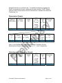
1
ProScale RF Receiver
User Manual
Linear Digital Measuring Systems
Accurate Technology, Inc.
270 Rutledge Rd. Unit E
Fletcher, North Carolina 28732
828-267-0253
This document is protected by the copyright laws of the United States of
America. No part of this document may be reproduced by any means, electronic
or otherwise, without the expressed written permission of Accurate Technology,
Inc.
© 2004 Accurate Technology, Inc.
Firmware Version 1.000
Attention
The ProScale RF Receiver is only compatible with
ProScale General Purpose Displays that are
equipped with an integral RF transmitter AND
firmware version 2.05 or above.
ProScale RF Receiver User Manual
Page 2 of 17
Table of Contents
Introduction .................................................................................................. 4
Terms........................................................................................................... 5
Installation.................................................................................................... 7
Configuration................................................................................................ 7
Command Format ............................................................................. 8
Output Modes.................................................................................... 9
Deleting a previous position record ................................................... 9
Full Message Display ........................................................................ 10
Binary mode output, ProRF emulation .............................................. 10
Command Format Examples ....................................................................... 12
Position Output Examples............................................................................ 15
Defaulting the Receiver to Factory Values................................................... 17
Setting the Receiver for Master Mode on the Serial Port ............................. 17
ProScale RF Receiver User Manual
Page 3 of 17
Introduction
Thank you for purchasing the ProScale/ProPanel RF receiver system. This radio
receiver unit is designed to be used in conjunction with Accurate Technology,
Inc. ProScale™ linear measuring systems that are equipped with integral RF
transmitters (display firmware version 2.05 or above).
The purpose of this system is to provide a one-way wireless data communication
channel between a ProScale measuring system and a computer or other
computing device. Depending on the receiver model that you have purchased,
the unit has the ability to receive signals from either a single ProScale display or
several displays.
The receiver provides RS-232 serial data in standard ASCII text format and may
be configured for various output formats. In addition, the receiver will support
standard baud rates from 2400 to 115200 bits per second.
The following is a list of features for the ProScale RF receiver:
•
Six output formats to support various data collection requirements.
•
Programmable data field delimiter character.
•
Programmable line terminator.
•
Record start sentinel character enable/disable.
•
Character echo enable/disable.
•
Baud rate selection.
•
System ID selection. Prevents interference from multiple in-range
systems.
•
Typical signal range: 50’ to 100’ depending on the environment.
•
Serial output transmit/receive reversal via jumper selection (null
modem). Allows unit to switch from slave mode (PC use) to master
mode (for use with other devices).
•
Receiver configuration is stored in non-volatile memory.
Configuration is completed using a standard terminal program such
as HyperTerminal™.
ProScale RF Receiver User Manual
Page 4 of 17
Terms
This section provides a brief description of terms used within this manual.
ASCII Text – Standard English text that is used in conjunction with computers.
This can include upper and lower case letters, numbers and punctuation.
Field – A field is an individual data element such as position, units or other
information.
Delimiter – A character that is used to separate individual fields from one
another, such as a space or tab.
Entry Record – A group of fields separated by delimiter characters that together
form an entry in a computer file.
Terminator – A special character(s) that is used to terminate an entry record.
Record Start Marker – A special character that is used to indicate the start of a
record being received. In this case, the marker is an asterisk (*).
ProScale RF Receiver User Manual
Page 5 of 17
Insert picture of front and back here.
ProScale RF Receiver User Manual
Page 6 of 17
Installation
The ProScale RF receiver is simple to install and connect to a PC.
1. Connect the low voltage DC power supply (provided) to the rear of the
receiver. Plug the power supply into an AC outlet. The top green LED
on the front of the receiver will illuminate.
2. Connect the male (pin) end of the DB-9 serial cable (provided) to the
rear of the receiver. Connect the female (socket) end to the PC serial
port. Note: If using a newer laptop computer, there may be no RS-232
port installed on your PC. In this case, it is recommended that you
purchase a USB/Serial adapter from your local office supply store.
3. Set the receiver in a location that is centrally located to receive signals
from your ProScale display(s). Do not place the receiver next to large
metal objects such as a filing cabinet as this may significantly reduce
the receiving range.
Configuration
After the receiver is connected to the computer and power applied, the unit can
be configured for operation.
Start a terminal emulation program such as HyperTerminal™. Configure the
terminal program for the serial port being used to communicate with the receiver.
The following is the default port settings of the receiver:
•
9600 baud
•
8 data bits
•
No parity
•
1 stop bit.
•
Flow Control: None
Although the receiver can be configured for different baud rates, the other
communications parameters are fixed and cannot be altered.
When the serial port has been configured and opened, the user can test the
communications by requesting the receiver’s firmware version. This is
accomplished by typing the command letter v or V followed by the ENTER key.
The receiver will respond with: “ProScale Receiver V1.000” or similar message.
ProScale RF Receiver User Manual
Page 7 of 17
Command Format
The receiver uses a standard format for all configuration commands.
1. A single command letter. Lower case letters allow the current parameter
state to be viewed without modification. Upper case letters allow the user
to change the parameter configuration.
2. One or more parameter characters. Parameter characters are only used
when modifying parameters. They have no effect when parameters are
viewed (lower case command letters).
The following is a list of command letters and their meanings:
V – Firmware version ID. Takes no parameters.
S – System ID. Used to configure the receiver to only accept signals from
ProScale displays that have the same system ID programmed.
Prevents other displays on other systems within radio range from
being received. The default is 0.
O – Output mode. Formats the record text for the desired data content.
See Output Modes on page 9 for more information. The default is
mode 3; position, units and display ID.
D – Configures the delimiting character that is used to separate fields
within a record. The default is a space.
E – Enables or disables the character echo when typing in data from the
terminal program. The default is ON.
M – Record Start Marker. Enables or disables the use of the new record
start (sentinel) character, which is an *. When enabled, each new
record received starts with an asterisk (*). The default is OFF.
T – Record Terminator. Each record can be terminated with either a
carriage return or carriage return and line feed. The default is CR/LF.
B – Baud Rate. Sets the baud rate used to communicate with the
receiver. The default is 9600 bits per second.
See a list of command examples beginning on page 12.
ProScale RF Receiver User Manual
Page 8 of 17
Output Modes
There are six output modes available on the ProScale RF receiver. The first five
are ASCII text formats and are outlined below:
Mode
0
1
2
3
4
Description
Position only
Position with units type (MM or IN)
Position with display (transmitter) ID
Position with units and display ID
Full Message Display, see next page.
The fifth mode is a binary data mode that provides partial message emulation for
Accurate Technology’s ProRF two-way radio system. This provides backward
compatibility for applications that were designed using the ProRF system.
In the case of output mode 0, an ASCII position is provided followed by the
programmed terminator (CR or CR/LF). In the other text modes, each field is
separated by the programmed delimiting character (space by default). The entire
line or record is then followed by the programmed terminating character.
The following are examples of output modes 0 through 3:
Output mode 0
Position<terminator>
Output mode 1
Position<delimiter>Units<terminator>
Output mode 2
Position<delimiter>ID<terminator>
Output mode 3
Position<delimiter>Units<delimiter>ID<terminator>
Deleting a previous position record
The ProScale General Purpose display has the capability of transmitting a
“delete previous measurement” signal by pressing the F2 key on the display.
This causes the text “DEL” to be displayed instead of a position. This can be
used to indicate to manually remove the previously recorded entry in a file.
ProScale RF Receiver User Manual
Page 9 of 17
Full Message Display
The full message display mode provides two types of messages depending on
the type of signal received.
•
•
Position Information
Status Information
When position information is received, the resulting message output is:
Position<delimiter>Units<delimiter>ID<delimiter>Signal Strength<terminator>
When status information is received, the resulting message output is:
Drift status<delimiter>Battery status<delimiter>ID<delimiter>Signal
Strength<terminator>
The position information is similar to Output Mode 3 with the addition of a signal
strength indication. Signal strength is represented by a value from 0 to 7 where 0
is a very weak signal and 7 is a very strong signal. This can be used for verifying
the quality of signal reception from a particular transmitter location.
The status information is used in conjunction with the drift monitor feature of the
ProScale General Purpose display. If the drift monitor is enabled on the display
and movement is detected outside the drift tolerance range, the display will
indicate a drift condition and a drift signal will be sent on the RF channel. If a low
battery condition is detected, this will also be indicated in the status information.
In the case of the Full Message Display option, the “delete previous
measurement” message is in the format:
DEL<delimiter>ENTRY<delimiter>ID<delimiter>Signal Strength<terminator>,
where DEL is substituted for the position and ENTRY is substituted for the units.
Binary mode output, ProRF emulation
This output mode is intended to be used with applications that were designed for
the ProRF two-way radio interface system. The output from this receiver is a
small subset of the functionality from the ProRF. Since the ProScale RF receiver
is one-way only, no acknowledgment signal can be sent back to the display.
Two different binary message packets are available from the ProScale RF
receiver. One reports a combination position/status message and one reports a
“delete previous record” message. Both of these message packets are
ProScale RF Receiver User Manual
Page 10 of 17
described below in an outline format. For detailed information regarding the
ProRF communication format, review the document entitled: “ProRF System
Definition and Communications Protocol Architecture” available from Accurate
Technology, Inc.
Measurement Sample
Receiver’s
Address
[255] (Base)
Sender’s
Address
[1 –254]
Command
Header
[‘A’]
Byte 1
Byte 2
Byte 3
Module
Type
[1]
Module
Status
[0 – 0xFF]
Encoder
Status
[0 – 0xFF]
Byte 7
Byte 8
Byte 9
RSSI
Value
[‘1’ – ‘7’]
1 = low
signal
7 = high
signal
Byte 4
Data
Capture
Latch
[0 – 0xFF]
Byte 10
Message
Packet
ID
[0 – 255]
Number of
Data Bytes
[13]
Byte 5
Byte 6
Units of ASCII Position
Operation
Data
[0] = mm. [‘0’ – ‘9’ ‘.’ ‘-‘]
[1] = in.
Byte 11
Bytes 12 - 19
Note: In the ProScale RF emulation mode, bytes 7 through 10 of the
Measurement Sample message are fixed at 1, 0, 1, and 1 respectively.
Delete Previous Measurement Sample
Receiver’s
Address
[255]
Sender’s
Address
[1-254]
Command
Header
[‘I’]
Byte 1
Byte 2
Byte 3
ProScale RF Receiver User Manual
RSSI
Value
[‘1’ – ‘7’]
1 = low
signal
7 = high
signal
Byte 4
Message
Packet
ID
[0 – 255]
Number of
Data Bytes
[0]
Byte 5
Byte 6
Page 11 of 17
Command Format Examples
The following examples demonstrate how to configure various parameters of the
ProScale RF receiver system. <ENTER> is the enter key on the PC
System
To display the current system ID (from default), type in:
s<ENTER>
The receiver responds with:
System = 0
To change the system ID to 21, type:
S21<ENTER>
The receiver responds with:
System now = 21
Output Mode
To display the current output mode (from default), type in:
o<ENTER>
The receiver responds with:
Output Mode = 3
To change the output mode to 4, type:
O4<ENTER>
The receiver responds with:
Output Mode now = 4
Delimiter Character
To display the current delimiter character (from default), type in:
d<ENTER>
The receiver responds with:
Delimiter = <space>
To change the delimiter to a tab character, type:
O<TAB><ENTER> Where <TAB> = the PC tab key.
The receiver responds with:
Delimiter now = <tab>
ProScale RF Receiver User Manual
Page 12 of 17
Echo Mode
To display the current echo mode (from default), type in:
e<ENTER>
The receiver responds with:
Echo mode on
To change the echo mode to off, type:
E0<ENTER>
Use 0 (zero) for off and 1 for on
The receiver responds with:
Echo mode off
Record Start Marker
To display the current record start marker status (from default), type in:
m<ENTER>
The receiver responds with:
Marker mode off
To change the record start marker mode to on, type:
M1<ENTER>
Use 0 (zero) for off and 1 for on
The receiver responds with:
Marker mode on
Terminator Type
To display the current terminator type (from default), type in:
t<ENTER>
The receiver responds with:
Terminator = <CR/LF> (0)
To change the terminator mode to CR only (1), type:
T1<ENTER>
Use 0 (zero) for CR/LF and 1 for CR only
The receiver responds with:
Terminator now = <CR> (1)
ProScale RF Receiver User Manual
Page 13 of 17
Baud Rate
To display the current baud rate (from default), type in:
b<ENTER>
The receiver responds with:
Baud rate = 9600
To change the baud rate to 19200, type:
B19200<ENTER>
The receiver responds with:
Baud rate will be = 19200
The baud rate change becomes effective 1 second after the command is issued
to allow the change message to be sent at the old baud rate.
Available baud rates are:
•
•
•
•
•
•
•
2400
4800
9600
19200
38400
57600
115200
Firmware Version ID
To display the current firmware version, type in:
v<ENTER> or V<ENTER>
The receiver responds with:
ProScale Receiver V1.xxx
Where xxx is the minor revision number.
If an invalid command letter is entered, the receiver will provide the following
response:
Use t, s, o, d, v, b, m or e.
Upper case to edit, lower case to view.
ProScale RF Receiver User Manual
Page 14 of 17
Position Output Examples
All examples are terminated with carriage return/line feed (CR/LF), not shown.
Output mode 0 example in inches
5.637
Output mode 0 example in millimeters
28.35
Output mode 1 example in inches with <space> delimiter
5.637 IN
Output mode 1 example in millimeters with <space> delimiter
5.637 MM
Output mode 2 example in inches with <space> delimiter, unit ID 3
5.637 3
Output mode 2 example in millimeters with <space> delimiter, unit ID 2
5.637 2
Output mode 3 example in inches with <space> delimiter, unit ID 3
5.637 IN 3
Output mode 3 example in millimeters with <space> delimiter, unit ID 2
5.637 MM 2
Output mode 4 example in inches with <space> delimiter, unit ID 3, signal
strength 5
5.637 IN 3 5
Output mode 4 example in millimeters with <space> delimiter, unit ID 2, signal
strength 7
5.637 MM 2 7
ProScale RF Receiver User Manual
Page 15 of 17
Output mode 5 position packet message, position 8.537 inches from display unit
ID 1, signal strength 5, message 34.
Byte Number
1
2
3
4
5
6
7
8
9
10
11
12
13
14
15
16
17
18
19
Value
255
1
‘A’
‘5’
34
13
1
0
1
1
1
‘‘
‘‘
‘‘
‘8’
‘.’
‘5’
‘3’
‘7’
Description
Destination address (receiver)
Display address ID
Position command character ASCII A
Signal strength ASCII 5
Message ID
Number of data bytes to follow
Always 1
Always 0
Always 1
Always 1
1 = inches, 0 = mm
space if positive, ‘-‘ if negative
hundreds digit
tens digit
ones digit
decimal point
tenths digit
hundredths digit
thousandths digit
Output mode 5, “delete previous measurement”, from display unit ID 1, signal
strength 7, message 21.
Byte Number
1
2
3
4
5
6
Value
255
1
‘I’
‘7’
21
0
Description
Destination address (receiver)
Display address ID
Delete measurement command, ASCII I
Signal strength ASCII 7
Message ID
Number of data bytes to follow
All values in binary except ASCII values where noted.
ProScale RF Receiver User Manual
Page 16 of 17
Defaulting the Receiver to Factory Values
In the event that the user wishes to restore the receiver to factory values,
complete the following:
1. Remove the four screws from the bottom of the receiver and remove
the top cover.
2. Locate and press the small pushbutton on the circuit board labeled
DEFAULT.
3. The AC LED will flash once to indicate that the factory parameters
have been restored.
4. Replace the top cover and re-install the four bottom screws.
Setting the Receiver for Master Mode on the Serial Port
By default, the ProScale RF receiver is designed to operate as a slave device. In
this mode, a standard serial cable is used to connect the unit to a PC for normal
operation.
In some cases, it may be required to use the receiver as a master device to
communicate with another electronic product. To help to facilitate this, the unit’s
transmit and receive pins on the DB-9 can be reversed via internal jumper
settings.
To reverse the transmit and receive pins, complete the following:
1. Remove the four screws from the bottom of the receiver and remove the
top cover.
2. Move jumpers blocks JP3 and JP4 from pins 1 and 2 to pins 2 and 3 on
each jumper.
3. Replace the top cover and re-install the four bottom screws.
A male-male DB-9 serial cable may now be used or a standard male-female
cable with a gender changer may be installed.
ProScale RF Receiver User Manual
Page 17 of 17