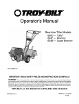
1
Save ThisManuam _'_
For FutureReference
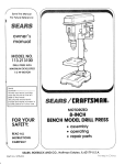
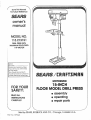
MODEL NO.
113.213151
DRmLLPRESS WiTH
MAXIMUM DEVELOPED
1 HP MOTOR
Serial
Number
Model and serial number
may be found at the rear
of the head.
You should record both
model and serial number in
a safe place for future use,
MOTORIZED
FOR YOU
SAFETY:
READ ALL
INSTRUCTIONS
CAREFULLY
® assembJy
® operating
e repair parts
Sold by SEARS, ROEBUCK AND COo_ Chicago_
Part No, SP5643
_L606_
U.S.A.
GENERAL
t, KNOW YOUR
R_a<_
atd
SAFETY
iNSTRUCTiONS
POWER TOOL
ur_de_st_rx,
_ file
tw_er,%
r_anuat
_uxi
iabeis affixed to the _ooI. Learn ,ts appi_cabor_ and
hm_tatfo_s as w,_Has the spec&c poter_tai hazar(js
pecuha_ to th,_stoo_
2. GROUND ALL TOOLS
[_'_
_X_
_S @u_,;iDDed
(:ors-:ar_
w£h
?_rl ; _DDrewed
{_-c Dnd
Z871) a! aF t_H_es 8ve, yx!ay eyegh:!_sses a,e not
safety glasses
P:ey oniy have mpact resistant
encq.s Aiso use face o_ dust mask ff cutting oper
abon _s dusty and ear ;;_;)t,;ttots (plugs or ¢,Aufis}
cunng ex_encted periods or ope_at:o;s
13. SECURE WORK
_C_Of
L!Sf
t4
_r_ wor_ln_
af3d
o_(_el
tQ
al_qnmen!
4. REMOVE ADJUSTING
FoH'r_
a
h_;_t_t
adiushng
'_urf!ff'lQ
KEYS
(_t checklnq
wrench_<
_c_ju,_ffr11(_r3]
;_[](i
AND WRENCHES
10 _t'e
are removed
th_ _. k_:!_'s
from
_rt_l
too_ before
_t Ot*i
5, KEEP WORK
AREA CLEAN
CkJ|tered
;_[_3as atwl
t)ertchet_
m_st
t:,_ _.dlppery
gue
not
6, AVOID DANGEROUS
DeW[
[)r(_De[
Neve
Ugh: power
tools
irlvlte
I_o w_x
accldeflt_,
or
F/col
saw(_ust
ENVIRONMENT
_n damp
nr
wet
_ocattor'_s
o{
exI:K_s;eth_',m to ram. Keep work area we!l hqhled
Provide adequate surrour_dmg work space}
7. KEEP CHIfLOREN AWAY
A}I v_S_tors should be k_pl a ;;a_e dista_c_:, from
work area
8, _AKE WORKSHOP
CHILD-PROOF
W_th padlocks, master sw_tches by remowng star.
_er keys
Or Slortng
tOOlS where ch4dren can't get
them
9. DON'T FORCE TOOL
it wilI do the _ob better and safer at me rate for
wR_cn _t wa_ designed
10. USE RIGHTTOOL
Don't force too_s or attachm.ent to do a leo _ was
not deslgnea fon
11. WEAR PROPER
APPAREL
Do no_ wear loose CtOth_ng g ioves necKhes or
lewe_ry ,nngs. wnst watches_ to get caught tn rnov.
_g parts
NONSLIP footwear _s recommended
Wear protectwe hair covering to con[am _ong hatr
Roti long sleeves peeve the elbow
12, USE SAFETY GOGGLES (HEAD PROTECTION)
Wear safety goggles
[must compty w_tn ANSI
o_rT,,DS
'_ fie(
u,,3_prona grouP, ping w_)e :)_ua "- l_, rr,r_
duCto _ _ 1R_' cord _< the {]roi._n(rlrtg w_rt:
connect the q_,_,_,nw_re tda lwr, _emn_na!
3. KEEP GUARDS tN PLACE
FOR POWER TOOLS
nov
Or
a
VIS©
PC DO/C _ ,%,{-!r_, W_!(_n
hands tC oDe-a[(
_tac_(:a
.
[o(;
DON'T OVERREACH
I'_'_'_b_ OtgDer
tO()_r_q
aqc
oah:ince
al
ai! t_mt)s
15. MAINTAIN TOOLS WITH CARE
_eeD too_s snaq:_ an,(_ c_:an for best and safes.;
;;eqormanc(
Follow mstru(;t_or_s for _ubncatmg and
cr,,angir}g accessones
16, DISCONNECT
TOOLS
Before serwcmq
wber chanqmg accessories such
a_ Modes [)_fs c_dtf_,rs etc
17. AVOID ACCIDENTAL
STARTING
Make sure sw_tcn ,_ m -OF:I::
cos€on before pJug*
grog m
18. USE RECOMMENDED
ACCESSORIES
Consun the owner_ manual for recommended
accessones
Follow the _nstruct}ons that accompany
the accessones
]he use of ,<[)roPer accessories
may cause hazards
19. NEVER STAND ON TOOL OR ITS STAND
Serious _njury could occur if the too_ is tipped Or _f
the cuthng tool _s acc_den_a_ y contacted.
Do not
store matenals above or near me too! such that it
_s necessary to stand on the _oo_ or its stand to
_each them.
20. CHECK DAMAGED
PARTS
Before furthe_ use of the [oo_ a guard or other part
that _s damageo should De carefully checked to
ensure that _twdl e_>erate DroDeny and perform its
re[ended function Check for alignment of moving
parrs Dmd_n9 or mowng parrs, breakage of parts.
rnoun[_ng, aria any other COnditions that may affect
its operation. A guara or other part that is damaged
should oe oroDerly reoaired o_ reoiaoed.
21. DIRECTION
OF FEED
Feed work into a blade or cutter against the d_rect_on of rotation of the blade or cutter only.
22. NEVER LEAVETOOL
RUNNING UNATTENDED
Turn power off. Don't leave tool until it comes to a
complete stop.
additional
safety
instructions
for drim presses
c
o
WARNING:
For your own safety, do not use your I
drill press unti] it is completely
assembled
and
installed
according
to the instructions
° . , and _i
unti_ you have read and understood
the follow- I
]
ing:
1. General
Safety
2. Getting
to Know
3. Basic
Drill
4. Adjustments
5. Maintenance
instructions
Press
Your
Drill
Operation
for Power
Press
Too_s,
2
........
.............
17
b
c. To avoid injury from parts thrown by the spring
follow instRJctions exactly as given and shown
in adjusting spring tension of quiti.
d
23
..........................
..........................
25
26
If the workpiece is too iarge to easily support with
one hand_ provide an a_xiiary support.
7, Location
Use the dril press in a wei lit area and on a ieve;
surface cfean and smooth enough to reduce the
risk of trips, slips, or falls Use it where neither the
eperator nor a casuat observer is forced to stand
in line with a potent af kickback
8. Kickback
Kickb_ck i._;the grabbing of the workpiece by the
rotating
tooi, The workp_ece
can be thrown at
very high speed in tI_e d rection of rotation. THIS
CAN CAUSE SERIOUS
tNJURY To reduce the
possibility of injury from kickback.
firmly to the table whenever
Buffing or sanding wheeis or drums should be
contacted on the side moving away from you, not
the side moving toward you.
Use oniy recommended
the instructions supplied
9. Protection:
accessories
and follow
with the accessory.
Guard for driihng information:
for accesseries, refer to the instructions
provided
wilh the accessories
Eyes, Hands, Face, Ears and Body
WARNING: To avoid being pulled
ning too] 1, Do NOT wear:
- g_oves
- necktie
- loose clothing
- jewetry
2. DO tie back tong hair
into the spin-
If any part of your drill p_ess is missing malfunctioning, has been damaged or broken .... such
as the motor switch, or other operating centre!,
a safety device or the power cord . . . cease
operating immediateiv
until the particular pa_t
is properly repaired or _epiaced.
[0 preverit the workpiece
from being tom
flora your hands, spinning of the tooi, shat
tering the tooi or being thrown, always properly support
your work so it won't shift or
b;nd or_ the tool:
..-.- Always posit_on BACKUP MATERIAL use
beneath the workpiece}
to cortact the eft
side of _he ce_umn
-- Whenever
possible, position the WORKPIECE to contac! lhe ieft side of the c,_:_lufnn
if
it iS tOO
short
or
the tabe _s t_/ted
claret:) soiidiy I(:)the table Use tabe slots
or (s/amp ng ledge around the o_ts de edge
of the table
.... When us_ngadriilpressViCE
awaysfasten _[ to the tabie.
..... Neve_ do any work "FREEHAND"
(handilo}d_ng workp_ece rather tf-'a_ suppo_ti_g t
on the tab e). except when poiishi_g
- Secu_e!y lock ;'-lead ar)d Support to Co!utah.
J-able Arrn tO support, and Table to "[abe
Arm before operating driiI press.
-- Never move the Head or Table whJle the
too} is running.
-_- Before starting the operation, jog the moto_
switch tO make sure the dritl or other cutting
tool does not wobbie or cause vibration
•_-. If a workpieee overhangs
!he _ab!e such
that it wili fali or tip if not hefd clamp it to
the tab]e or provide auxiliary supper1
--o Use fixtu{es
for uNusuai operations
to
adequately hofd, guide and position workp_ece.
-_ Use the SPINDLE SPEED recommended
for the specific operation and workpiece
material--check
the iabei inside the Belt
6. Stability
of Dri_l Press
If there is any tendency of the dril] press to tilt or
move during any use, boit it to the floor or a fiat
piece of !i_" exterior
p_ywood _arge enough to
stabilize the drill press
Bolt the plywood to the
underside of the Base. so 4t extends at least to
both sides Make sure the plywood won't trip the
operater. Do not use pressed
wood panels-they can break unexpectediy.
Clamp the workpiece
possible.
Never p_ace your fingers in a position where
they could contact the drill or other c_ttir_g tooi
if the workpiece
should unexpectedly
shift or
your hand sho_id slip
e.
Never climb on the drill press Table it couid
break or put! the entire drili press down ors,
you
f
Turn the motor Switch Off and put away
Switch Key when !eaving the dril press.
g
to avoid injury from thrown work o_ tool con.tact do NOT perform _ayout assembly, or
setup work on the table wh]e the c_xtt_ng tooi
is rotating.
the
/(
i
¸¸
i!i!i!iii
iiiii iii:i i!iiiiil) !i i ii Iii!iiii
ii)ii !iii ! :i !ii
i , i :ili: !ililiiii
i ! i : iiii i ii i:
10i Use °nly accessories designed for this drill
Press to avoid se!ious injury from thrown bro;
pa_s or work pieces.
cutting large dlameter holes:
the workpiece iirmly to the tablel
Otherwise the cutter may grab and spin it at
high speed.
Use
:
only one piece, Cup-type, hole cutters.
DO NOT use fly cutters or multi-part hole cutters as they can come apart or become unbalanced in use.
Keep speed below 1,500 RPM.
b. Drum sanders must NEVER be operated on
this drill press at a speed greater than 1800
RPM.
c. Do not install or use any drill that exceeds 7" in
length or extends 6" below the chuck jaws, They
can suddenly bend outward or break.
d, Do not use wire wheels, router bits, shaper cutters, circle (fly) cutters or rotary planers on this
drill press.
11_ Note and Follow the Safety Warnings and instructions that Appear on the Panel on the
Right Side of the Head:
121 This Drill Press has 12 speeds as listed below:
250 RPM
990 RPM
340 RPM
i 550 RPM
390 RPM
1620 RPM
510RPM
600 RPM
650 RPM
See inside of belt guard for specific placement of
belt on pulleys.
13. Think Safety. Safety is a combination of operator
common sense and alertness at all times when the
drill press is being used.
WARNING: Do not allow familiarity (gained from]
frequent use of your drill press) to become com- I
monplace.
Always remember that a carelessJ
fraction of a second is sufficient to inflict severe I
injury,
j
The operations of any power tool can result in foreign
objects being thrown into the eyes, which can result
in severe eye damage. Always wear safety goggles
comply with ANSI Z87.t (shown on Package) before
commencing power tool operation. Safety Goggles
are available at Sears retail stores.
WEAR YOUR
i "
_WARNING
1900RPM
2620 RPM
3100 RPM
gmessary of terms
1. Workpiece
The item on which the cutting operations is being
performed.
2. Drill
The cutting tool used in the drill press to make holes
in a workpiece,
4. Revolution Per Minute (R.P.M.)
The number of turns completed by a spinning object
in one minute.
5, Spindle Speed
The RPM of the spindle,
_E
3. Backup Material
A piece of wood placed between the workpiece and
table ....
it prevents wood in the workpiece from
splintering when the drill passes through the backside of the workpiece .... also prevents drilling into
the table top.
table of contents
Page
Page
General Safety Instructions for Power Tools ......
Additional Safety Instructions for Drill Presses ....
Glossary of Terms ..........................
Table of Contents ...........................
Motor Specifications and Electrical
Requirements ..............................
Unpacking and Checking Contents .............
Table of Loose Parts ........................
Location and Function of Controls ..............
Assembly ................................
Assembly of Column and Table Hardware...
Installing the Table .....................
Installing the Head .....................
Mounting Motor ........................
Installing Motor Pulley ...................
Tensioning Belt ........................
Installing Belt Guard Knob ...............
Motor Connections .....................
Installing Feed Handles .................
Installing the Chuck .....................
Installing Light Bulb .....................
2
3
5
5
6
7
8
9
10
10
11
11
12
12
12
13
14
14
14
16
Adjusting the Table Square to Head .......
Bevel Scale ...........................
Getting to Know Your Drill Press ..............
On-Off Switch .........................
Drilling to a Specific Depth ...............
Locking Chuck Desired Depth ............
Removing Chuck and Arbor ..............
Re-Installing the Chuck and Arbor .........
Basic Drill Press Operation ..................
Installing Drills .........................
Positioning Table and Workpiece ..........
Tilting Table ...........................
Hole Location .........................
Feeding ..............................
Adjustments ..............................
Quill Return Spring .....................
Maintenance ..............................
Lubrication ...............................
Recommended Accessories ..................
Trouble Shooting ..........................
Repair Parts ..............................
16
16
17
19
20
20
21
22
23
23
24
25
25
25
25
25
26
26
26
27
28
and
motor specifications
o
emectricamrequirements
pE nCAT O.
s
Th!s powe_ too! is equipped with a 3-conductor cord
and grounding type plug, approved by Underwriters'
Laboratories and the Canadian Standards Association.
The ground conductor has a green jacket and is attached to the toot housing at one end and to the ground
prong in the attachment plug at the other end.
This drill press is designed to use a 1725 RPM motor
only, Do not use any motor that runs faster than 1725
RPM It is wired for operation on 110-120 volts. 60 Hz.
alteinat ng current.
WARNING: To avoid injury from unexpected
startup, do not use blower or washing machine I
motors or any motor with an automatic reset I
overload protector.
I
CONNECTING
TO POWER
SOURCE OUTLET
This machine must be grounded while in use to protect
the operator from electric shock.
This plug requires a mating 3-conductor grounded type
outlet as shown,
if the outlet you are planning to use for this power tool
is of the two prong type, DO NOT REMOVE OR ALTER
THE GROUNDING PRONG IN ANY MANNER. Use
an adapter as shown and always connect the grounding
lug to known ground.
It is recommended that you have a qualified electrician
replace the TWO prong outlet with a properly grounded
THREE prong outlet.
Plug power cord into a 110-120V properly grounded
type outlet protected by a 15-amp. dual element time
delay or Circuit breaker.
An adapter as shown below is available for connecting
plugs to 2-prong receptacles,
Not all outlets are properly grounded. If you are not
sure that your outlet, as pictured below, is properly
grounded, have it checked by a qualified electrician.
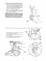
WARNING: The green grounding lug extending 1
from the adapter must be connected to a perma- t
nent ground such as to a proper_y grounded
outlet box.
WARNING: To avoid electric shock, do not touch I
the metal prongs on the plug, when installing or
removing the plug to or from the outlet.
I
WARNING!
Failure to properly
ground this
power tool can cause electrmution or serious
shock, particularly when used in damp locations, or near metal plumbing;if shocked, your
reaction could cause your hands tohit the cutring tool.
GROUNDING
SCR_,,.,
3-PRONG
LUG
\
_
_
MAKE
SURE
THIS
'if power cord is worn or cut, or damaged in any
Way, have it replaced immediately
to avoic
shock or fire hazard.
3-PRONG
ADAPTER
PLI IG
NOTE: The adapter illustrated is for use only if you
already have a properly grounded 2-prong receptacle.
Adapter is not allowed in Canada by the Canadian Electrical Code.
ALWAYS USE A
PROPERLY GROUNDED
OUTLET
Your unit is for use on less than 120 volts. It has a plug
that looks like the one above,
The use of any extension cord will cause some loss of
power. To keep this to a minimum and to prevent overheating and motor burn-out, use the table below to
determine the minimum wire size (A.W.G) extension
cord. Use only 3 wire extension cords which have 3prong grounding type plugs and 3-pole receptacles
which accept the tools plug.
Extension Cord Length
0-25 Feet
2_50 Feet
5i-100 Feet
Wire Size A.W.G
16
16
12
IS
unpacking
and checking
TABLE
WARNING: To avoid injury from unexpected
starting
or electrical shock, do not pmug the
power cord into a source of power. This cord
must remain unpJugged whenever you are working on the drill press.
Model 113.213151 Drill Press is shipped complete in
one box.
1. Unpacking and Checking Contents
a. Separate all "loose parts" from packaging materials and check each item with "Table of Loose
Parts" to make sure all items are accounted for,
before discarding any packing material.
WARNING:
if any parts are missing,
do not
attempt to assemble drill press, plug in the
power cord, or turn the switch on until the missing parts are obtained and are instamled correct[Y"
contents
OF LOOSE
PARTS
gtem
Description
A Table ..............................
B Column Support Asm ..................
C Owner's Manual ......................
D Motor ..............................
E Bag of Loose Parts ...................
F Base ...............................
G Head Asm ...........................
H Box of Loose Parts ...................
I
I
I
I
J
2. Remove the protective oil that is applied to the
table and column. Use any ordinary household type
grease and spot remover.
WARNING: To avoid fire or toxic reaction, never
use gasoline, naptha or similar highly volatile
so vents.
3. Apply a coat of paste wax to the table and column
to prevent rust. Wipe all parts thoroughly with a clean
dry cloth.
°/
A
H
D
C
City.
1
1
1
1
2
1
1
1
A
\
,i_iii_
iI'_
_ It_r_
Descr
_ p_ior_
_
Oty,
A FeedHandle
::.
:
i.i:i:i..i...
B Key Drift.,.
,:
; ..........
C
WrenchHex "L',3mm'''', ...: .... .i:...i:,
D
Wrench Rex"L 5mm ,.i: ......
:..:..i
E Cranki. ...........
i: .....
i.,::...,
GF
Clamp
WrenchColumn
Hex Box...............
24rnrn ................ i ......
:
3
1
1
1
i
_---
1
D_,_
--
__
A
-'_
__P
_
C,,_,-
G
List of Loos Parts in Box
Item
Description
H Chuck ..............................
I Chuck Key ..........................
Qty.
1
1
i
!
J
J
List of Loose Parts in Bag
item
Description
J Screw Hex HD. M10 x 1.5-40 ...........
K Key-Switch.,
._.., .................
L Knob (Guard) :
....................
Qty.
4
1
1
N
,!
List of Loose Parts in Bag
Item
Description
O idler Pulley Assembly ........
.... i. ,.
P Pulley-Motor .........................
Q Belt "V" 3/8 x 24 .....................
R Belt "V" 3/8 x 26 .....................
S Screw-Hex HD. M8 x 1.25-20 ...........
T Washer-5/16 x 7/8 x 5/64 ..............
U Nut-Hex M8 x 1.25 ...................
Qty.
1
1
1
1
4
8
4
$
8
_
_
_i i _
i
_ _
i
_
T
U
ooation
and function
1. BELTTENSION
HANDLE...
Turn handle counter
clockwise
to apply tension
to belt, turn handle
clockwise to release belt tension.
2. BELT TENSION LOCK HANDLES...
Tightening
handles locks motor bracket support and BELT
TENSION
HANDLE to maintain correct belt distance and tension.
3. HEAD LOCKS,
., Lock the head to the column.
ALWAYS have them locked in place while operating the drill press.
4. SUPPORT
LOCK...
Tightening locks table support to column. Always have it locked in place while
operating the Drill Press.
5. TABLE
CRANK
. . . Turn clockwise
to elevate
table. Support lock must be released before operating crank.
6. TABLE
position
BEVEL LOCK...
from 0"-45 °
7. TABLE
various
positions
LOCK...
Locks the table in any
Allows table to be rotated
and locked.
of controls
9. CHUCK...
Holds drill bit or other recommended
accessory to perform desired operations,
10, BEVEL SCALE . .. Shows degree table is tilted
for bevel operations. Scale is mounted on side of
arm.
11. SPRUNG CAP,..
spring tension.
Provides means to adjust quill
12. DEPTH SCALE...
Allows operator to adjust drill
press to drill to a desired depth.
13. DRILL "ON-OFF" SWITCH ... Turns drill press
on and off ....
also used to lock drill press in off
position.
14. LIGHT "ON-OFF"
and off.
SWITCH...
Turns the light on
t5. CHUCK KEY...
Used to tighten drill in the chuck
and also to loosen the chuck for drill removal.
16, DEPTH SCALE LOCK..,
at selected position.
Locks the depth scale
in
8. FEED HANDLE
. . . For moving the chuck up or
down. One or two of the handles may be removed
if necessary
whenever
the workpiece
is of such
unusual shape that it interferes with the handles.
16
14
P
13
Q
Q
0:._.
£::::
10
6
7
TABLE REMOVED
FOR CLARITY
assembly
I WARNiNG: For your own safety, never connect
l plug to power source outlet until all assembly
FRAMING SQUARE MUST BE TRUE.
Check its accuracy as illustrated below.
I steps are completed.
DRAW
LIGHT
LINE ON BOARD
-
TOOLS
NEEDED
......................
EDGE
ALONG THIS
'_',
X,,,.__ ,_
//
STRAIGHT EDGE OF
BOARD 3/4" THICK-THIS EDGE MUST BE
PERFECTLY STRAIGHT
COMBINATION
SQUARE
J
MEDIUM
SCREWDRIVER
8-iNCH ADJUSTABLE
WRENCH
--
ASSEMBLY
HARDWARE
SHOULD BE NO GAP OR OVERLAP WHEN
SQUARE IS FLIPPED OVER IN DOTTED POSiTiON
OF COLUMN
AND
03
TABLE
1Omm DIA. x 40rnm
1. Position base on floor, Remove protective covering
and discard
COLUMN
soPpO.T
2. Remove protective sleeve from column tube and
discard. Place column assembly on base. and aligr
holes in column support with holes Ln oase,
LONG
.
BOLT
/
_,"
f
/
3, Locate (4) four lOmm Di& x 40mm long bolts (see
illustration) in loose parts bag.
4, Install a bolt in each hole through column support
and base and tighten with adjustable wrench.
COLUMN
=L__/PTABLE
5. Locate table crank and support lock in loose parts
bOX,
PORT
6. Install support lock from left side into table support
and tighten by hand.
7. Install table crank assembly and tighten set screw
with a 3mm HEX "E' wrench, Do not overtighten. Set
screw should be tightened against the flat section
of the shaft.
SUPPORT
LOCK
TABLE
SUPPORT
COLUMN
8. Position column collar over rack and tighten set
screw in collar using 3rnm HEX "L" wrench supplied
in loose parts bag. Collar shou d not be angled on
the column. Only tighten set screw enough to keep
collar _nplace: rack should still slide freely in collar
NOTICE: To avoid column or collar damage,
not ovettighten set screw.
COLUMI
do
10
/
INSTALLING
SUPPORT
LOCK
THE TABLE
TABLE
t. Loosen support lock and raise table support by
turning table crank cRockwise until support is at a
working height level. Tighten support lock.
TABLE
SUPPORT
RACK
TABLE
SUPPORT
Remove protective covering from table and discard. Place table in table support and tighten table
lock (located under table) by hand.
TABLE
LOCK
mNSTALLING
t
TABLE
THE HEAD
[ pounds,
CAUT'ON:Carelully
The head
lift assembly
head.
weighs
about 551
1. Remove protective bag from head assembly and
discard. Carefully lift head above column tube and
slide it onto column making sure head slides down
over column as far as possible, Align head with
table and base.
2. Locate (2) two lOmm dia. x 12ram long set
screws (see illustration) in loose parts bag.
.i_; _ f
lOmm DIA. X 12mm
SET SCREW
"
3. Install a set screw in each hole (as indicated) on
the right side of the head, and using a 5mm hex
"L" wrench, tighten the two head lock set screws.
11
HEAD
LOCK
M(
:KET
MOUNTING
1 Locate four MOTOR
(4) 8mm Dia x 20mm long hex head f
j/
bolts, eight (8) flat washers, and four (4) hex nuts
among loose parts.
MOTOR
JY _'_
2. install hex head bolts through motor bracket on
head.
j,zJ
f
--, ,jJ.- /
3. Place motor in position so motor base slots line up
with motor bracket SlOtS. Install flat washers and
hex nuts as illustrated, iDo not tighten)
. _:4
BASE
_
HEX
NUT
4. Motorshaftshould be as c_oseas possibletocenter
of round opening in belt guard.
HEAD
BOLT
8ram DIA. x 20turn LONG BOLT
HEX NUT
FLAT
WASHER
AT WASHER
MOTOR
PULLEY
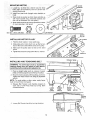
iNSTALLiNG
MOTOR
PULLEY
SET
SCREW
1. Find the motor pulley in loose parts _3ag.
2, Slide pulley onto motor shaft. Line up the flat surface on the motor shaft with the set screw in pu Iley.
3. Make sure the pulley does not rest on the lower
guard.
4. Tighten the set screw using a 3ram Hex"L" wrench.
FLAT
SURFACE
STRAIGHT EDGE
iNSTALLiNG
AND
TENSIONING
BELT
WARNING: To avoid injury due to accidental
starting always turn drill press off and remove
switch key before making belt adjustments.
t. Place a straight edge such as a piece of wood,
metal, or framing square across the top of pulleys.
2. Move the motor upward untilthe pulleys are in line.
Tighten the motor mount nuts using an adjustable
wrench,
NOTE: To avoid rattles or other noise, motor frame
\
must not touch lower belt guard.
3. Release Belt Tension Lock handles located on
each side of Drill Press head by turning them
counterclockwise.
\
\
LOWER
BELT
GUARD
BELT
TENSION
LOCK
HANDLE
MOTOR
MOUNT
NUTS
MOTOR
BELT
TENSION
HANDLE
4
_oosen Belt Tension handle by turning clockwise.
12
5. Locate center pulley assembly in loose parts bag
and place in proper hole.
SPINDLE
PULLEY
6. Locate two (2) V-belts in the loose parts bag,
7, Use speed chart inside belt guard to choose speed
for drilling operation. Install belts in correct position
for desired speed, The longer of the two belts is
always positioned between the spindle pulley and
idler pulley.
NOTE: Refer to inside belt guard for Recommended
Drilling Speeds.
IDLER
8. Apply tension to belt by turning Belt Tension Handle
counter clockwise until belt deflects approximately
1/2 inch by thumb pressure at its center.
9, Tighten Belt Tension Lock Handles.
--
NOTICE: Over tensioning
belt may cause motor
not to start or damage bearings.
10. If belt slips while drilling,
readjust
belt tension.
BELT
TENSION
HANDLE
BELT GUARD
5ram DIA × 8ram LONG
SCREW
PAN HD,
BELT GUARD KNOB
tNSTALUNG
BELT GUARD
KNOB
1. To attach belt guard knob, locate knob and 5ram
Dia. x 8mm long pan hd. screw in loose parts bag.
Install screw in hole located in guard and attach
knob turning until tight,
WARNING: To avoid possible injury keep guard
l in place and in proper working order while oper[ating.
!3
PULLEY
BELT
TENSION
LOCK
HANDLE
MOTOR
CONNECTIONS
WARNING: For your own safety, never connect I
' p|ug to power source outlet until aH assembJy
steps are completed.
BLACK WIRE TO
TERMINAL #1
COPPER
POST
GREEN WIRE
TO GREEN SCREW
1. Open motor connector box cover located o q underside of motor using a flat blade screwdriver.
STRAIN RELIEF
GROOVE
WARNING: To avoid electrocution, never connect anything
but the ground wire (colored
green) to the green screw.
4/HITE WIRE
TO TERMINAL #4
;ILVER POST
2. Remove GREEN SCREW and insertthrough round
metal terminal on the end of the GREEN wire of
power cord,
3. Reinsert GREEN SCREW in threaded hole that it
was removed from and tighten securely,
4 Insert terminal end of WHITE wire on spade termina (next to silver o_)
marked #4 on tile motor.
Push terminal firmly until seated.
5 Insert terminal end of BLACK wire on spade terminal !next to copper post) marked #1 on the motor,
Push terminal firmly until sea_eo.
MOTOR
POWER
CORD
_
MOTOR
BLACK,_.
/BLACK
_
CORD
_
WHITE
GREEN
BLACK
@
GREEN
IGROUND)
6. Close motor connector box being sure tl_at power
cord is seated n strain relief groove and tighten
box cover screws.
7. Do not plug in 3ower cable.
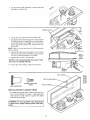
iNSTALLiNG
FEED HANDLES
I. Locate three (3) feed handles among loose parts.
2. Screw the feed handles into the threaded no_es in
the hub and tighten.
HUB
FEED
HANDLE
INSTALLING
THE CHUCK
Clean out the TAPERED HOLE in the chuck. Clean
both tapered surfaces on the arbor with a clean
cloth. Make sure there are no foreign particles sticking to the surfaces. The slightest piece of dirt on
any of these surfaces wilt prevent the chuck from
seating properly, This will cause the drill to
"wobble.
_ARBOR
CLEAN THIS
SURFACE
14
\
\
2. Slide the chuck up over the arbor as illustrated.
SPINDLE
CHI
SUPPORT
LOCK
\
3. Unlock support lock and raise table so its about
two (2) inches below tip of chuck.
4, Turn chuck sleeve clockwise and open jaws in
chuck completely.
5, Turn feed handles counterclockwise and force
chuck against table until chuck is secure.
CHUCK
SLEEVE
HANDLE
!5
|NSTALUNG
LIGHT BULB
than 60 watt) into the
/
!ii
¸¸¸_V¸¸::
_iill i_:__ _i_I _i_i_i,_i_
i,.
_
_ _
_ _i:_i!i_i_i_ _!_
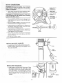
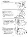
ADJUSTING
TO HEAD
i
!
i
i_
_ _
THE TABLE SQUARE
NOTE: The combination
square must be 'true.
"Unpacking
and Checking
Contents"
secuon
method.
See
for
1. Insert a straight ground steel roe ('not included_
approximately 3" long into chuck and tighten.
2. With table raised to working height and lOCked Dn
column place combination square flat on table oeside roe.
3. If an adjustment is necessary, moosen the set
screw under bevel lock with 3ram Hex "L"
wrench, then loosen the table bevel lock with the
24mnq flat wrench (included). (These adjustments
are located under the table),
4, Align the table souare to the rod by rotating the
table until the square and rod are in line.
5. Retigmen table bevel lock.
6. Retigmen set screw,
BEVEL _
BEVEL SCALE
/_"
/
TABLE
/
NOTE: The bevel scale has been included to orovide
a quick method for beveling the table _o approximate
angles. If precise accuracy is necessary, a souare, or
other precision measuring tool should be used to position the table.
1. To use the bevel scale
U
ao the following:
a. Loosen set screw and table bevel lock (see step
3 above).
D Move table so desired angle or bevel scale is
straight across from zero line on table support.
c. Retighten table bevel lock and set screw.
POINTER
SCALE
16
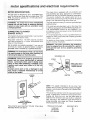
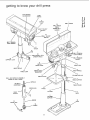
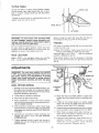
getting te know your dri_Spress
FEED SPRING
ADJUSTMENT
FEED
SPRING
t-
17
SPRING
CAP
26
DRILL SPEED
TABLE
(nNSJDE BELT
GUARD)
LIGHT "ON-OFF"
SWITCH
1
BELT GUARD
_o
27
DRILL "ON-OFF"
SWITCH
2
BELT TENSION
LOCK HANDLE
,t8
CHUCK
19
ARM
2
BELT TENSION
LOCK HANDLE
20
_BLE BEVEL LOCK
(UNDER TABLE)
23
SUPPORT
/
LOCK
BEVEL
22
SCALE
21
TABLE LOCK
3
BELT TENSION
HANDLE
16
DEPTH
SCALE
LOCK
4
HEAD LOCK
15
DEPTH SCALE
iNDICATOR
'5
FEED HANDLE
6
COLUMN COLLAR
f
14
DEPTH SCALE
QUILL AND SPINDLE
iNSIDE OF DRILL
ASSEMBLY
PRESS
7
TABLE SUPPORT
SPINDLE
SPLINES
(GROOVES)
8
TABLE CRANK
WEDGE KEY
13
TABLE
12
COLUMN
RACK
(TEETH)
RACK
11
COLUMN
24
CHUCK KEY
_,,_.......__._
ARBOR
H
-\
17
_,J
T_I_ Diili Press
/
ii
....
i_i,_ii_
i_i i
¸
'_i_
i_i
has t2 sp_ed_
o_n_...,u,
,,,,,D°_
340 RPM
390 RPM
510 RPM
600 RPM
650 RPM
as listed
990
1550
1620
1900
2620
3100
belowi
:
RPM
RPM
RPM
RPM
RPM
RPM
SPEEDS
340
390
510
600
650
990
1550
1620
1900
2620
3!00
ASSEMBLY
. . . Covers
operauon of drill press.
pulleys
BELT TENSION LOCK HANDLES...
Tightening
handles locks motor bracket support and BELT
TENSION
HANDLE to maintain correct be!t dtStance and tenston.
3, BELT TENSION HANDLE ... Turn handle counter
clockwise
to apply tension to belt. turn handle
clockwise to release belt tension.
4. HEAD LOCKS...
Lock tne head to the column
ALWAYS qave thenq locked in place while operab
_ng the drill press
6. COLUMN
COLLAR ... Holds the rack to the column. Rack remafns movable in collar to permit
table support movements.
DEPTH
drllleo.
15
DEPTH SCALE _NDICATOR...
depth selected on depth sca=e
16
DEPTH SCALE LOCK...
to selected aeoth
1•
SPRING CAP...
spnng _ension
18
CHUCK...
accessory
SCALE
. ..
Shows
Provides
depth of hope being
Indrcates
dr_t ing
Locks :no oepth scale
means to adjust qu_ll
Holc_s dril b_t or otlqer recornnended
to perform posited operations
20.
TABLE BEVEL LOCK...
Position from 0 -45
21.
TABLE LOCK...
Table can be rotated
3ositions and poked
22.
BEVEL SCALE ...
for bevel operahons
arm.
Rides on column to support
8. TABLE CRANK . . . Turn clockwise to elevate
table. Support lock must be released before operating crank.
Locks the table Jn any
in various
Shows degree table is tiited
Scale _s mounted on side of
23. SUPPORT
LOCK.
. Tigntentng locks table support to column. Always have =tlocked in place while
operating the Dri Press.
9 RACK... Combines with gear mechanism to provide easy elevation of table by hand operated table
crank
10. BASE...
Supports Drill Press For additional stability, holes are provided in base to bolt Dril Press
to floor. {See 'Additional
Safety Instructions for Drill
Presses.q
COLUMN SUPPORT...
Supports column, guides
rack. and provides mounting holes for column to
ease
12. COLUMN...
a one-piece
ment.
14
9. ARM...
Extends oeyond tabte suDoort for mount
_ng ancJ ahgntng the table.
5. FEED HANDLE . . . For moving the chuck up or
down, One or two of the handles may oe removeo
if necessary
whenever
the worKo_ece _s of such
unusual shape that it interferes w_th the handles
7. TABLE SUPPORT,..
arm and table.
of belts
IN RoPoMo
250
1. BELT GUARD
and belt during
11
placement
on pulleys.
SPINDLE
2
see inside of be!t guard for specific
Connects iqead, table, ana ease on
tube for easy alignment and move-
24
CHUCK
KEY .
which wil "pop"
of i[ This action
ing of the chuck
Js _urnec "ON"
substitute
order
25
BELT TENSION,..
Refer to section "Assem 31y-Installing and ]ension_ng Belt"
26
DRILLING SPEED... Can be changed by placing
the uelt in any of the STEPS tgroovesl n the puF
leys. See Spindle Speed inside belt guarG
. . It is a self-ejechng
chuck key
out of tlqe chuck wnen you let go
is designed to help prevent throwkey from the cnuc_ when power
Do qot use any other key as a
a new one if damagea of iost
To determine the ao#roximate drilling speed
to the table inside the belt guard.
13. TABLE . . . Provides working surface to support
workpiece.
18
refer
27. ORILL "ON-OFF"
SWITCH .... Has Socking feature, THIS FEATURE
IS INTENDED
TO HELP
PREVENT
UNAUTHORIZED
AND POSSIBLE
HAZARDOUS
USE
BY
CHILDREN
AND
OTHERS.
Insert KEY into switch.
NOTE:
Key is made
of yellow
pmastic.
To turn drill ON . .
Insert finger under switch lever and pull.
®
To turn drill OFF...
Push lever in,
In an emergency;..
, the drill bit BINDS...
STALLS
• . . STOPS...
or tends to tear the workpiece loose
• . . you can QUICKLY turn the drill OFF by hitting the
switch with the palm of your hand.
To lock switch in OFF position..,
hold switch IN with
one hand...
REMOVE key with other hand.
WARNING: For your own safety, always push the
switch "OFF" when drill press is not in use...
remove key and keep it in a safe place.., also..
in the event of a power failure (all of your lights
go out) or blown fuse or tripped circuit breaker,
turn switch off,.,
and remove the key. This will
prevent the drill press from starting up again
when the power comes back on.
t9
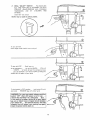
DRiLLiNG
TO A SPECIFIC
DEPTH
To drill a BLIND hole Inot all the way through) to a
given depth, proceed as follows.
1. Mark the depth of the hole on the side of the workpiece.
2. Loosen the depth scale lock.
3. With the switch OFF. bring the drill down until the
TIP or tips of the drill are even with the Mark.
DEPTH
SCALE
LOCK
4. Turn the depth scale counterclockwise until it stops
moving,
5. Tighten the depth scale lock.
DEPTH
SCALE
6. The drill will now be stopped at this aepth until the
depth scale is readlusted.
MARK
....
L
ANOTHER
WAY
--
DEPTH
SCALE
l,
!. With the switch OFF. loosen the depth scale lock.
2. Place workplece on table. Adjust table until the tip
of the drill is just a little above the top of the workpiece, turn the depth scale counter clockwise to
zero.
DEPTH
SCALELOCK
3, Turn the depth scale clockwise until the depth
scale indicator pornts to the desired drilling depth
on the depth scale.
4. Tighten the depth scale lock.
DEPTH_
DEPTH SCALE
INDICATOR
5. The chuck or drill will now be stopped after traveling downward the distance selected on the depth
scale.
LOCKING
CHUCK
DESIRED
DEPTH
1. With the switch off--loosen the depth scale lock.
2. Turn the feed handles until the chuck _s at the
desired aepth. Hold feed handles at this position.
2O
(30
DEPTH SCALE
LOCK
3. Turn the depth scale clockwise until it stops.
4. Tighten the depth scale lock.
5. The chuck will now be held at this depth when the
feed handles are released.
:ALE
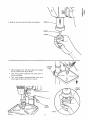
SPINDLE KEY
HOLE
REMOVING
CHUCK
QUILL KEY
HOLE
AND ARBOR
ARBOR
LOCKING
COLLAR
CHUCK
SLEEVE
1. With switch off -- adjust depth scale to hold drill
at a depth of (3) three inches. (See instructions for
"Locking chuck at desired depth").
2. Align key holes in spindle and quill by rotating
chuck by hand, (See illustration)
3, Insert key wedge
the
into key holes.
4, Tap key wedge lightly until the chuck and arbor
fall out of spindle.
NOTE: Place one hand below chuck to catch it when
it falls out,
WEDGE KEY
CHUCK
CHUCK
BODY
21
RE-INSTALLiNG THE
CHUCK.
AND ARBOR
C_ea_ the tapered surface on the arbor with a clean
cloth, Make sure there are no foreign particles stiCK_ng to the surface. The slightest piece of dirt on
th_s surface will prevent the arbor from seating
properly
This will cause the drill to "wobble."
2, S_ide arbor inlo spindle
on drilt press,
3. Push up on chuck/arbor
assembly as you rotate
them. You wil! feel rectangular end of arbor slip
mto a notch in the spindle,
SPINDLE
WARNING: Make sure the rectangular end of the 1
arbor has slipped into the notch in the spindle 1
before going on to step 4. Failure to follow this_
direction
may allow the chuck to come iooseJ
during operation, fly out, and hit the operator.
I
CHUCK
BODY
SUPPORT
LOCK
4, Unlock support lock and raise table so its about
two (2) inches below tip of chuck.
5, Turn chuck sleeve
chuck completely,
clockwise
and open
jaws
6, Turn feed handles counterclockwise
and
ChUCk against table until arbor is secure,
\
in
force
CHUCK
SLEEVE
FEED
HANDLE
CHUCK
22
iii
press operation
basic
__ Securely
lock Head and Support to Column,
Table
Arm to support, and Table to Tab!e
Arm
before operating drill press.
._ Never
move the Head or Table while the
_:oot is running.
_ Before
starting the operation, jog the motor
switch
to make sure the drill or other cutting
tool
does not wobble or cause vibration.
If a vvorkpiece
overhangs the table such that
it wilt fall or tip if not held clamp it to the
table
or provide auxiliary support.
...... use
fixtures
for unusual
operations
to
adequately
hold, guide and position work-
Follow the foilowinginstruction,
s foroperat ng you_ drll
press toget the best _esu ts aridto Rin}r__
ze t!e ikeli
hood of personal injury.
WARNING: For your own safety, a_ways observe]
I the safety precautions
here and on pages 2. 3, l
Land
4.
"
'
j
!, Protection: Eyes, Hands, Face, Earsand Body
WARNING: To avoid being pulled
ning toolI. Do NOT wear:
- gloves
- necktie
- loose clothing
- jewelry
2. Do tie back long hair
into the spin-
a.
If any part of your drill press is rams{rig, f.'nalfuncItching,- has been damaged or broken
such
as the motor switch, or other ope_atmg control.
a safety device or the power cord
, . (:ease
operating immediately
until the particu!ar part
is p_operly repaired or replaced
b.
Never place your fingers in a position where
they could contact the drill of other cutting toci
if the workpiece
should unexpectedly
shift or
your hand should slip.
c,
To avoid injury from parts thrown by the spring,
follow instructions
exactly as gwen and shown
in adjusting spring tension of quill
d,
To prevent the workpiece from being torn from
your hands, spinning of the tool. shattering the
tool or being thrown, always properly support
your work so it won't shift or bind on the tool:
-- Always position BACKUP
MATERIAL (use
beneath the workpiece)
to contact the left
side of the column.
-- Whenever
possible,
position the WORKPIECE to contact the !eft side of the column-if
it is too short or the table is tilled,
clamp solidly to the table use table stets or
clamping ledge around the outside edge of
the table.
When using a drill press VICE, always fasten
it to the table.
-- Never do any work "FREEHAND"
(handholding workpiece rather than supporting it
on the table), except when polishing
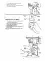
INSTALUNG
DRILLS
2.
piece.
..... Use
the SPINDLE
SPEED recommended
for the specific operation and workpiece materia!-check
the panel on the left side of
the
head for drilling information:
for accessories,
refer to the instructions provided with
the
accessories.
÷ Never
c_imb on the drili press Table, it could
break or pull the entire drill press down on you,
g Turn
the
motor Switch Off and put away the
Switch
Key when leaving the drill press,
h To avoid
injury from thrown work or tool contact,
do NOT
perform
layout, assembly,
or setup
work on the table while the cutting tool is rotating.
Use only
accessories
designed
for this drit_
press
to avoid
serious injury from thrown broken parts
or work pieces.
a. When
cutting
large diameter holes:
Clamp
the workpiece
firmly
to the table.
Otherwise
the cutter may grab and spin it at
high speed.
Use only
tightening
the chuck
Tighten the drill sufficiently,
while drilling.
Turn the chuck
key
terclockwise
to loosen.
hote cutters,
Keep
speed
below
1,500 RPM
b.
Drum
sanders
this drill
press
RPM.
c.
Do not install or use any drill that exceeds 7" in
length or extends 6" below the chuck jaws. They
can suddenly
bend outward or break.
Do not use wire wheels, router bits, shaper cutters, circle
(fly) cutters or rotary planers on the
drill press.
d.
must NEVER be operated on
at a speed greater than 1800
iN CHUCK
With the switch off and the key removed, insert drill
into chuck far enough to obtain maximum GRIPPING
of the CHUCK JAWS..,
the jaws are approx, t" long.
When using a small drill do not insert it so far that the
jaws touch the flutes (spiral grooves) of the drill.
Make sure that the drill is CENTERED
in the chuck
before
one piece, cup-type,
DO NOT
use fly cutters or multi-part
hole cutters as they can come apart or become unbalanced
in use.
;K KEY
with the key.
JAWS
so that it does not SLIP
clockwise
to
tighten_-_coun..
23
POSITiONiNG
TABLE AND WORKPmECE
Lock the table to the column in a position so that the
tip of the drill is just a little above the top of the workpiece.
Always place a piece of BACK-UP MATERIAL (wood
plywood
. .) on the table underneath the workplece
This will c,revent "SlOlintering" or making a heavy burr
on the underside of the worKpiece as the drill breaks
through. To keep the backup materia from spinning
out of control, it must contact the left side of the column
as Ilustrated.
WORKPIECE
\
WARNING: To prevent the workpiece
or the
backup r_aterial from being torn from your hand
while drilling, position them against the left side
of the column, if the workpiece or the backup
material are not long enough to reach the col°
umn, clamp them to the table. Failure to do this
could result in personal injury.
BACK-UP
MATERIAL
For small pieces that cannot be clamped to the table.
use a drill press wse (Optional accessory.)
WARNING: The vise must be clamped or bolted
to the table to avoid injury from spinning work
and vise or tool breakage,
WORKPIECE
DRILL
PRESS
"X
ViSE
BOLT OR CLAMP
ViCE SECURELY
24
TILTING
TABLE
To use the table in a bevel (tilted) position, loosen
the set screw under table bevel lock with a 3mm
Hex "L" wrench• Loosen bevel lock with the 24mm
flat wrench.
BEVEL
LOCK
Tilt table to desired angle by reading bevel scale. Retighten bevel lock and set screw.
BEVEL SCALE
U
SET SCREW
Before turning the switch ON, bring the drill down to
the workpiece lining it up with the hole location.
WARNnNG: To avoid injury from spinning workI
or tool breakage, always clamp workpiece and
backup material securely to table before operating driBIpress with the tabte tilted.
FEEDING
Pull down on the feed handles
to allow the drill to cut.
To return table to original position: loosen set screw
and bevel lock, tilt table back to 0 ° on bevel scale, and
retighten set screw--then tighten bevel lock.
HOLE
with only enough
effort
Feeding TOO SLOWLY might cause the drill to burn
• . . Feeding TOO RAPIDLY might stop the motor...
cause the belt or drill to SLIP . . . tear the workpiece
LOOSE or BREAK the drill bit.
LOCATION
Make a DENT in the workpiece where you want the
hole.., using a CENTER PUNCH or a SHARP NAIL•
When drilling metal, it may be necessary
the tip of the drill with motor oil to prevent
drill tip.
to lubricate
burning the
adjustments
NOTCH
BOSS
WARNING: For your own safety turn switch
"OFF" and remove plug from power source outlet before making any adjustments.
To avoid
injury from thrown parts due to spring release,
follow instructions carefully, and wear eye goggles.
QUILL RETURN
CAP
JAM NUT
(OUTER)
NOTCH
SPRING
1. With the chuck at its highest possible position, turn
the depth scale clockwise until it stops and tighten
the depth scale lock. This will prevent the quill dropping while tensioning the spring.
2. Lower table for additional clearance,
NUT
(INNER)
8. Move stop nuts and depth pointer to upper most
position and check tension while turning feed handles.
3. Work from left side of Drill Press.
4. Place screwdriver in lower front notch of spring
cap, and hold it in place while loosening and removing jam [outer] nut only.
9. if there is not enough tension on spring, repeat
steps 4-8 moving only ONE notch each time and
checking tension after EACH repetition.
5. With screwdriver remaining in notch, loosen large
standard [inner] nut (approximately 118")until notch
disengages from boss on head. DO NOT REMOVE
THIS NUT.
10. Proper tension is achieved when quill returns gently
to fuli up position when released from 3/4" depth.
! 1. When there is enough tension after checking, replace jam nut and tighten to standard nut, BUT do
not overtighten
against standard nut.
6. Carefully turn screwdriver counter clockwise and
engage next notch in boss. DO NOT REMOVE
SCREWDRIVER
12. Check quill whib feeding to have smooth and unrestricted
movement,
If movement
is too tight,
loosen jam nut and SLIGHTLY
!oosen standard
nui until unrestricted
Retighten jam nut
7. Tighten standard nut with wrench onty enough to
engage boss. Do not overtighten as this will restrict
quill movement.
25
maintenance
¢:::
WARNING: For your 0wn safety, turn switch 1
'OFF" and remove plug from pov_er source out'_
let before maintaining
or lubiricating your drill I
Frequently blow out any dust that may accumulate in,
side the motor.
A coat of furniture-type paste wax applied to the table
and column will help to keep the surfaces clean.
I WARNING: To avoid shock or fire hazard, if the I
power cord is worn or cut, or damaged in any I
way, have it replaced immediately.
I
r-o
.o
lubrication
All of the BALL BEARINGS are packed with grease at
the factory. They require no further lubrication.
Periodically lubricate the gear and rack, table elevation
mechanism, the SPLINES (grooves) in the spindle, and
the RACK (teeth of the quill). See "Getting to Know
Your Drill Press."
WIRING DIAGRAM
.-.
o
Sears Recommends
Drill Bits .........................
Hold-Down and Guide ..................
Drill Press Vises ...................
Drill Press Mortising Kit .............
Hole Saw up to 2 1/2" dia. max .......
5 pc. Stop Collar Set ...............
the Following Accessories
See Catalog
9-2457
See Catalog
See Catalog
See Catalog
See Catalog
Mortising Chisel and Bits ............
See Catalog
Clamping Kit ......................
See Catalog
15 Piece Drum Sanding Kit ..........
See Catalog
Sanding Drums ................
9-2497 -- 9-2498
Buffing Wheels up to 4" dia. max ......
See Catalog
Power Tool Know-How Handbook ........
9-29117
Sears may recommend other accessories not listed in the manual.
See your nearest Sears store for other accessories.
Do not use any accessory unless you have received and read complete instructions for its use.
i ¸
_i!-i¸¸ .
o
troubWe shooting
]
WARNING:
Forshooting.
your own safety, turn switch "OFF" and always remove pUug from power source outlet-]
before
troubge
® CONSULT YOUR LOCAL SEARS SERVICE CENTER IF FOR ANY REASON MOTOR WILL NOT RUN.
TROUBLE
Noisy Operation
PROBABLE
CAUSE
REMEDY
1. Incorrectbelttension.
1. Adjust tension, See section
"ASSEMBLY--TENSIONING
BELT."
2. Lubricate spindle. See "Lubrication"
section.
3. Checking tightness of retaining nut on
pulley, and tighten if necessary.
4, Tighten setscrews in pulleys.
2, Dry Spindle.
3. Loose spindle pulley.
4. Loose motor putley,
Drill Burns
1. Incorrect speed,
1, Change speed. See section "Getting
To Know Your Drill Press"...
DRILLING SPEED,
2. Retract drill frequently to clear chips.
2, Chips not coming out
of hole.
3, Dull Drill.
4, Feeding too slow.
5. Not lubricated.
Drill leads off...
hole not round.
3, Resharpen or replace drill.
4. Feed fast enough,,, allow drill to cut,
5. Lubricate drill. See "Basic Drill Press
Operation" section.
1. Hard grain in wood or
lengths of cutting
lips and/or angles
not equal.
2. Bentdrill bit.
2. Replace drill bit.
Wood splinters on
underside.
1. No"back-up material"
under workpiece.
1. Use"back-up material".,. See Basic
Drill Press Operation" section.
Workpiece torn
loose from hand.
1. Not supportedor
clamped properly.
!. Support workpiece or clamp it... See
"Basic Drill Press Operation" section.
Drill Binds in
workpiece.
1. Workpiece pinching drilt
or excessive feed pressure.
2. Improper belt tension.
1. Support workpiece or clamp it... See
"Basic Drill Press Operation" section.
2. Adjust tension,.. See section
"ASSEMBLY--TENSIONING
BELT,"
Excessive drill
runout or wobble.
1, Bent drill.
2. Worn spindle bearings.
3. Drill not properly
installed in chuck.
4. Chuck not properly installed.
1, Use a straight drill.
2. Replace bearings.
3. Install drill properly... See"Basic
Drill Press Operation" section,
4, Install chuck properly,,, refer to
"Unpacking and Assembly Instructions
,., INSTALLING THE CHUCK."
QuilmReturns
tooslowor
too
fast.
1. Spring has impropertension.
1. Adjust spring tension,.. See section.
"Adjustments--Quill Return Spring."
Chuck will not stay
attached to spindle
it falls off when
trying to install it.
1. Dirty, grease, or oil on the
tapered inside surface of chuckor on the spindles tapered
surface.
1. Using a household detergent-clean the
tapered surface of the chuck and spindle to
remove all dirt, grease and oil.
1. Resharpen drill correctly, or replace.
27
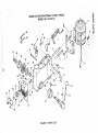
PARTS LiST FOR CRAFTSMAN
15" DRILL PRESS
MODEL NO. 113.213151
.,...49
47
46
48
45
\
44
\
39
14
41
13
43
42
16
34
33
32
31
25
30
19
26
24
28
27
29
FIGURE
1 PARTS
LiST
11
PARTS
LiST
FOR
CRAFTSMAN
MODEL
15" DRILL
NO. 113.213151
Always order by Part Number--Not
FIGURE
Key
No
b,3
¢O
1
2
3
4
5
6
7
8
9
!0
11
!2
13
14
!5
16
i7
18
19
20
21
22
23
24
25
Part
No.
1 PARTS
Description
817317
Lever-Adjusting
STD835016 * Screw-Hex HD. M8 x 1.25-16
817495
Support-Motor Bracket
817329-2
Cord-Power
STD375008 * Connector-Wire
817336
Mount-Motor
STD852012 * Lockwasher 12mm
STD841217 * Nut-Hex M12 x 1.75
817557
Motor
STD840812 [ * Nut-Hex M8 x 1.25
STD851008 * Washer-M8 x 16 x 1.6
817328-2
Cord-Motor
STD835020 * Screw-Hex HD.
M8 x 1.25-20
817516
Support-Motor Bracket
817320
Knob-Motor Adjusting
817494
Handle-Belt Tension
817391
Screw-Hex Soc. Set
M10 x 1.5-12
817303
Pin-Stop
821735
Hub Asm,
817343
Lock-Depth Screw
817300
Guide-Scale
817546
Knob
817344
Rod
817774
Ring-Depth Stop w/Scale
STD852005 * Lockwasher-Ext, M5
* Standard Hardware Item -
PRESS
by Key Number
u==
"=O
LiST
Key
No
Part
No.
26
27
28
29
30
31
32
33
34
35
36
37
38
39
40
41
42
43
44
45
46
47
48
49
50
--
816755-4
817552
820240
820248-2
817354
817547
9-22256
816113
821741
STD841015
817308
821755-2
821738-2
817307
817306
817305
817304
817778-2
60475
817321
STD833012
816755-3
63418
813317-6
813317-8
SP5643
Description
Screw-Pan HD M5 x 0.8-8
Box-Switch
Screw-Pan HD M5 x 0.8-16
Screw Pan HD M4.2 x 1.4-8
Switch-Rocker
Cover-Switch Plate
1 Key-Switch
Switch-Locking
Lead 3"
* Nut-Hex M10 x 1,5
Screw-SL Special 10 x 1,5-27
Nut Hex M12x 1,5-6
* Nut Hex M12 x 1.5-10
Cap-Spring
Spring-Torsion
Retainer-Spring
Seat-Spring
Head w/Pointer & Trim
Tie-Wire
Socket-Bulb Asm.
* Screw-Pan HD M6 x 1.0-12
Screw Pan HD M5 x 0.8-12
Clamp-Cord
Wrench Hex "L" 3mm
Wrench Hex "L" 5mm
Owners Manual
(Not Illustrated)
May Be Purchased Locally.
Repair Parts
repmr pans
PABTS
i
LIST FOR CRAFTSMAN
15" DRILL PRESS
MODEL NO. 113.213!51
13-
i
4
!(
7
/
9
Always order by Part Number-Not
FIGURE
Pa_
KeYi
NO.
No ;
2 PARTS
Key
No
Description
by Key Number
L_ST
!
Pa_
No.
m
I
Description
m_
1
2
3
4
5
6
7
8
817325
508047
817544
STD315225
STD303240
' 817779-3
817543
817548
I
i
9
817358-1
* Standard
Hardware
10
1]
12
13
14
15
16
17
t8
Knob
Pivot-Idler
Pulley-Center
* Bearing-Ball 15ram
Belt-"V" 3/8 x 24
Guard wtLabe_s
Pulley-Motor
Screw-He× Soc. Set
M6 x 1.6-10
Screw-Wash HD.
M6 x 1.0-16
Item -- May Be Purchased
Locaily
3O
821734
816755-3
817537
817545
STD315245
817536
821742
817511-2
820294
.....
InsertPulley
Screw-PN HD, M5 × 0,8-8
Ring-Retaining
Pulley-Spindle
* Bearing-Ball 20ram
Spacer
Nut-Pulley M24 × 1.5 L.H.
"Belt "V" 3/8 x 26
Washer- Feam
repair
parts
PARTS LeST FOR CRAFTSMAN
15" DRILL PRESS
MODEL NO. 113.213151
12
J
11
Always
order by Part Number--Not
FIGURE
Key
No.
Part
No.
1
2
3
4
5
6
81 7309
81 7310
81 7311
STD315235
817535
817532
3 PARTS
Description
Locknut M17x 1.0
Ring-Locking
Washer
*Bearing-Ball
17mm
Gasket-Quill
Tube.Quill
by Key Number
LIST
Key
l
Part
NOl
I
NO.
j
817339
817340
817341
817531
STD315245
8
9
10
11
12
P
* Standard Hardware Item -- May Be Purchased Locally.
31
I
I
....
uescrlptlorl
I
t
Key-Chuck
Chuck
Arbor
Spindle
*Bearing Ball
repair parts
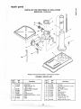
PARTS LIST FOR CRAFTSMAN
15" DRILL PRESS
MODEL NO. 113.213151
°_---.
19
2o/
Always order by Part Number--Not
by Key Number
FIGURE 4 PARTS
Key
No
Pa_
No.
Key I
No I
Description
i
--,--,=--,---4
1
2
817478
820245
3
4
5
6
7
8
9
821861
821880
821882
821881
STD836040
817577
817348
LIST
Collar-Rack
Screw-Hex Soc. Set
M6 x 1,0-10
Support-Table w/Indicator
Tube-Column
Rack
Support-Column
* Screw-Hex HD. M10 x 1,5-40
Base
Crank
32
Pa_
No,
----
1
12
13
14
!5
16
17
18
19
817288
I 821732
1817290-1
1817777-1
I 817575
1817294
I 817350
I 817349
1817391
20
1821926
Description
........
=
Pin-Gear
Screw-Hex HD. M16 x 2.0G5
Clamp-Table
Arm-Table w!Scale
Table
Clamp-Column
Gear-Helical
Worm-Elevation
Screw-Hex Soc. Set
M10x !.5-12
Wrench Hex Box 24ram
NOTES
i!i
33
NOTES
34
NOTES
m
35
f
f
MOTORIZED
MODEL
NO.
113.213151
For the repair 8r repJacement parts you need
Call 7 am - 7 pro, 7 days a week
I -eOO-3GG-PART
(1-800-356-72781
DR_LLPRESS WITH
MAXaMUM DEVELOPED
] HP MOTOR
Forin-home majorbrand repairservice
Call 24 hours a day, 7 days a week
1-8OO-4oRBPA|R
(1-800-473-7247)
The model number of your
Drill Press will be found on a
plate attached to the left
side of the head.
When requesting service or
ordering parts, always provide the following information:
•
•
•
•
Product Type
Model Number
Part Number
Part Description
For the location of a
Sears Repair Service Center in your area
Call 24 hours a day, 7 days a week
1-800--488-1222
Fer information e. purchasing a Sears
Maintenance Agreement or to inquire
about an eeisting Agreement
Call 9 am - 5 prn, Monday-Saturday
1-800-827-6655
America's
Repair
Specialists
SEARS, ROEBUCK AND CO., Hoffman Estates, IL 60179 U.S.A.
Part No. SP5643
Form No, SP5643-2
Printed in China
t0/95