Download Craftsman 921.166380 Troubleshooting guide

Transcript
Mode_ No. 921.166380
• Safety instructions
installation
& Operation
_, Maintenance
& Storage
_, Troubleshooting
Guide
Parts List
Before using this product,
read this manual and follow
at! its Safety Runes and
Operating instructions.
_, Espa_ol,
Sears,
Www.sea
Roebuck
rs. COrn
08/11/2006
Part No. E101586
and Co.,
Hoffman
Estates,
p. 10
IL 60179
U.S.A°
Table of Contents
Page
Warranty ..............................................................
See Belo_
Safety SymboUs ..........................................................
1
Umportant Safety Unstructions & Guidelines
1
.....................................
Specifications ............................................................
2
GUossary ................................................................
2
Duty Cycle ..............................................................
2
Parts & Features
3
.........................................................
UnstaHation & AssemMy ....................................................
4
Operating Procedures
5
.....................................................
Detaching Unit from Dolly ..................................................
6
Maintenance .............................................................
6
Storage
6
................................................................
Troubleshooting
Guide .....................................................
7
Exploded View ...........................................................
8
Parts List ...............................................................
9
Espa_ol
................................................................
ONE YEAR FULL WARRANTY
ON CRAFTSMAN
10
AIR COMPRESSOR
Ufthis Craftsman Air Compressor falls due to manufacturer's defects in materiaU or workmanship
within one year of the date of purchase, RETURN UTTO THE NEAREST SEARS STORE OR
SERVUCE CENTER UNTHE UNUTED STATES and it wHUbe repUaced or repaired (at our option),
free of charge,
Ufthis Air Compressor is used for commerciaU or rentaU purposes, this warranty applies for onUy 90
days from the date of purchase, This warranty gives you specific legal rights and you may also
have other rights which vary from state to state,
Sears, Roebuck and Co., Dept. 817WA,
Hoffman Estates, IL 60179
Safety Symbols
The information listed below should be read and understood by the operator, This information is given to protect the
user while operating and storing the air compressor, We utilize the symbols below to allow the reader to recognize important
information about their safety,
indicates an imminently hazardous situation which, if not
avoided, wiii result in death or serious injury,
indicates a potentially hazardous situation which, if not
avoided, may result in minor or moderate injury,
indicates a potentially hazardous situation which, if not
avoided, could result in death or serious injury
When used without the safety alert symbol indicates a
potentially hazardous situation which, if not avoided, may
result in property damage,
mmportant Safety
_, Save aH instructions
mnstructions
and Guidelines
WARNING: This product contains one or more chemicals
known to the State of California to cause cancer and birth
defects or other reproductive harm,
Wash hands after handling.
improper operation or maintenance of this product could result in serious injury and/or property damage, Read and
understand all of the warnings and safety instructions provided before using this equipment,
The air compressor should be operated on a dedicated 15 amp circuit, if the circuit does
not have 15 free amps available, a larger circuit must be used, Always use more air
hose before utilizing extension cords, All extension cords used must be 12 gauge with a
maximum length of 25 ft, The circuit fuse type must be a time delay, Low voltage could
cause damage to the motor,
Risk of Moving
Parts
if the air compressor is in operation, all guards and covers should be attached or
installed correctly, if any guard or cover has been damaged, do not operate the
equipment until the proper personnel has correctly repaired the equipment, The power
cord should be free of any moving parts, twisting and/or crimping while in use and while
in storage,
Risk of Burns
There are surfaces on your air compressor that while in operation and thereafter can
cause serious burns if touched, The equipment should be allowed time to cool before
any maintenance is attempted, items such as the compressor pump and the outlet tube
are normally hot during and after operation,
Risk of Falling
Operation of the air compressor should always be in a position that is stable, Never use
the air compressor on a rooftop or elevated position that could allow the unit to fall or
be tipped over, Use additional air hose for elevated jobs,
i
Risk from Flying Objects
Always wear ANSi Z87,1 approved safety glasses with side shields when the air
compressor is in use, Turn off the air compressor and drain the air tank before
performing any type of maintenance or disassembly of the hoses or fittings, Never point
any nozzle or sprayer toward any part of the body or at other people or animals,
important Safety instructions
& Guide/ines
Risk of Breathing
i
Avoid using the air compressor in confined areas, Always have adequate space
(12 inches) on all sides of the air compressor, Also keep children, pets, and others out of
the area of operation, This air compressor does not provide breathable air for anyone or
any auxiliary breathing device, Spraying material wiii always need to be in another area
away from the air compressor to not allow intake air to damage the air compressor filter,
Risk of
E_ectrica_ Shock
Never utilize the air compressor in the rain or wet conditions, Any electrical issues or
repairs should be performed by authorized personnel such as an electrician and should
comply with all national and local electrical codes, The air compressor should also have
the proper three prong grounding plug, correct voltage, and adequate fuse protection,
Risk of
Never operate the compressor near combustible materials, gasoline or solvent vapors,
if spraying flammable materials, locate the air compressor at bast 20 feet away from the
spray area, Never operate the air compressor indoors or in a confined area,
E×p_osion
or Fire
Risk of Bursting
Always drain the air compressor tank daily or after each use, if the tank develops a leak,
then replace the air compressor, Never use the air compressor after a leak has been
found or try to make any modifications to the tank, Never modify the air compressor's
factory settings which control the tank pressure or any other function,
Specifications
Pump ..........................
Motor ...........................
Bore .......................................
Stroke ......................................
Voltage Single Phase .......................
Minimum Circuit Requirement ................
Oil-lube direct drive
1,0 HP (induction)
1,65"
1,26"
120 VAC
15 Amps
Air Tank Capacity .........................
Cutqn Pressure .............................
Cut-out Pressure ...........................
SCFM @ 90 PSi ................................
Oil Capacity .........................
Oil Type ........................
4 Gallons
95 PSi
125 PSi
2,4
90 mL or 3 oz,
SAE 30 Non-detergent
Glossary
CFM:
Cubic feet per minute,
SCFM: Standard cubic feet per minute; a unit of measure
for air delivery,
PSI¢:
Pounds per square inch gauge; a unit of measure
for pressure,
ASME: American Society of Mechanical Engineers,
California Code: Unit may comply with California Code
462 (I) (2)/(M) (2),
Cut-In Pressure: The air compressor wiii automatically
start to refill the tank when the pressure drops
below the prescribed minimum,
Cut-Out Pressure: The point at which the motor stops
when the tank has reached maximum air
pressure,
Code Certification:
Products that bear one or more of
the following marks: UL, ULc, ETL CSA, have
been evaluated by OSHA-certified independent
safety laboratories and meet the applicable
Underwriters Laboratories Standards for Safety,
Duty Cycle
This is a 50% duty cycle air compressor,
could damage the air compressor,
Do not run the air compressor more than 30 minutes of one hour, Doing so
Parts & Features
See figures below for reference.
f
Regulator Gauge
indicates the outgoing air pressure to the tool and is
controlled by the regulator.
Quick Connect
Offers a quick release feature for
attaching and removing the air hose.
Chock Valve
When the pump is not in operation the valve closes to
retain air pressure inside the tank. An internal
component.
Tank Pressure Gauge
indicates the reserve air pressure in the tank.
Outlet Tube
Tank Safety Valve
Used to allow excess tank pressure to escape into
the atmosphere. This valve should only open when
the tank pressure is above the maximum rated
pressure.
Pressure Switch
This controls the power to the motor and also the
cutdn/cut-out pressure settings. This switch serves as
the Auto-On/Off positions for the unit.
Pressure
Belbf Valve
The pressure relief valve located on the side of the
pressure switch, is designed to automatically
release compressed air when the air compressor
reaches cut-out pressure. The released air should
only escape momentarily and the valve should then
close,
Pressure
Relief Tube
J
J
Regulator
The air pressure coming from the air tank is controlled
by the regulator, To increase the pressure turn the
knob clockwise and to decrease the pressure turn the
knob counterclockwise,
Used to drain condensation
I Tank
Located
DrainatValve
bottom of tank.
from the air tank.
Air Intake Fitter
Provides clean air to the pump and must always be
kept free of debris. Check on a daily basis or before
each use.
e!
I
mnsta ation
& Assembly
The air compressor should be turned off, unplugged from
the power source, the air bled from the tank and the unit
allowed time to cool before any maintenance is performed,
Personal injuries could occur from moving parts, electrical
sources, compressed air or hot surfaces, The quick
connect assembly must be attached before use, Failure
to assemble correctly could result in leaks and possible
injury, if unsure of assembly instructions or you experience
difficulty in the assembly please call your local service
department for further instruction,
AssembJy
1, Remove air compressor, handle assembly, hardware,
oil bottle, intake filter, manual and accessories from
the styrofoam,
2, Remove the plastic plug from the compressor intake
port, (see diagram below)
8, Install the filter in the compressor intake port,
(see diagram below)
4, Remove the oil fiii cap from the crankcase and fiii until
the oil reaches the top of the red dot in the sight glass,
Oil capacity is 3 oz, (seebe!ow)Use SAE-30 non-deter
gent (API CG/CD heavy duty motor oil), Under extreme
cold weather conditions, 32 ° F (0°C) or below, use
SAE-10 weight oil,
5, Replace the oil cap,
6, Attach the handle to the frame with the saddle bolts
from the outside of the handle and the knobs on the
inside,
Estimated
Assembly
Time: Approximately
5 minutes
Getting Started - Location of the Air Compressor
The air compressor should always be located in a dean,
dry and well ventilated environment, The unit should have
at minimum, 12 inches of space on each side, The air filter
intake should be free of any debris or obstructions,
Check the air filter on a daily basis to make sure it is dean
and in working order,
Grounding instructions
This product should be grounded, in the event of an electrical
short circuit, grounding reduces the risk of electric shock by
providing an escape wire for the electric current,
This product is equipped with a cord having a grounding
wire with an appropriate grounding plug, (See the figure at
top right corner,) The plug must be plugged into an outlet
that is properly installed and grounded in accordance with
all local codes and ordinances, Check with a qualified
electrician or service personnel if these instructions are not
completely understood or if in doubt as to whether the tool
is properly grounded,
Grounded
Outlet
Grounding
Pin
improper installation of the grounding plug wiii result in a
risk of electric shock, if repair or replacement of the cord
or plug is necessary, do not connect the grounding wire to
either fiat blade terminal, The wire with insulation having an
outer surface that is green with or without yellow stripes is
the grounding wire, Check with a qualified electrician or
serviceman if the grounding instructions are not completely
understood, or if in doubt as to whether the product is
properly grounded, Do not modify the plug provided,
if it wiii not fit the outlet, have the proper outlet installed
by a qualified electrician,
This product is for use on a circuit having a nominal rating
of 120 volts and is factory-equipped with a specific electric
cord and plug to permit connection to a proper electric
circuit, Make sure the product is connected to an outlet
having the same configuration as the plug, An adapter
should not be used with this product, if the product must
be reconnected for use on a different type of electric circuit,
qualified service personnel should make the reconnection,
Extension
Cords
Use only a 3-wire extension cord that has a 3-blade
grounding plug and a 3-slot receptacle that will accept the
plug on the product, Make sure your extension cord is in
good condition, When using an extension cord, be sure to
use one heavy enough to carry the current your product will
draw, Cords must not exceed 25 feet and No, 12 AWG size
must be used, An undersized cord will cause a drop in line
voltage resulting in loss of power and overheating,
Break in Procedures
No break in procedure is required by the user,
This product is factory tested to ensure proper operation and
Operating
Procedures
Daily Start-Up Procedures
1. Set the Auto-On/Off bver to the Off position.
2. inspect the air compressor, air hose, and any
accessorbs/toob being used for damage or obstruction.
if any of these mentioned items are in need of repair/
repUacement, contact your bcaU authorized service deabr
before use.
3. Cbse the drain vaUve.
4. Check the oH bveU of the pump.
5. Connect the air hose to the quick connect socket on
the reguUator assemMy by inserting the quick connect
pUugon the air hose into the quick connect socket. The
quick connect socket collar will snap forward and lock
the plug into place providing an air tight seal between
the socket and plug. To release the air hose push the
collar back on the quick connect socket.
6. Plug the power cord into the proper receptacle.
7. Turn the Auto-On/Off lever to the On-Auto position and
the compressor will start and build air pressure in the
tank to cut-out pressure and then shut off automatically.
8. Adjust the regulator to a PSI setting that is needed for
your application and be sure it is within the safety
standards required to perform the task. If using a
pneumatic tool, the manufacturer should have
recommendations in the manual for that particular
tool on operating PSI settings.
9. The air compressor is now ready for use. The following
inflation and cleaning accessories packaged with this
unit should only be operated at maximum pressure
of 90PSk blow gun, rubber-tapered nozzle, inflation
needles, adapter, and blow gun adapter.
B
Daity Shut-Down Procedures
1. Set the Auto-On/Off lever to the Off position.
2. Unplug the power cord from the receptacle.
3. Set the outlet pressure to zero on the regulator.
4. Remove any air tools or accessories. When draining
the tank, always use ear and eye protection. Drain the
tank in a suitable location; condensation will be present
in most cases of draining.
5. Open the drain valve allowing air to bleed from the
tank. After all of the air has bled from the tank, close
the drain valve to prevent debris buildup in the valve.
I
When draining the tank, always use ear and eye protection.
Drain the tank in a suitable location; condensation will be
present in most cases of draining.
Water that remains in the tank during storage will corrode
and weaken the air tank which could cause the tank to
rupture, To avoid serious injury, be sure to drain the tank
after each use or daily.
I
ing unit from dolly
For removing, read steps below first before attempting to remove or replace the air compressor to the dolly:
Do not use the dolly for any other means other than transporting this aur compressor.
Do not move air compressor/dolly combo without tightening the knob that safely secures the compressor to the dolly.
Removing the air compressor from the doily:
1. The air compressor should be turned off and
unplugged from the power source.
2. Turn the knob on the bottom of the dolly counter°
clockwise until the knob releases from the air
compressor. (This should be 1°2 revolutions)
3. While holding the dolly cart handle with one hand,
rift up on the air compressor handle to remove the
compressor.
%
Reattaching the air compressor to the dolly:
1, The air compressor should be turned off and
unplugged from the power source.
2. Align the compressor's rubber isolators with the
depressions in the dolly frame.
3. insert knob bolt into the air compressor and rotate
clock°wise until tight. (if the compressor is not properly
aligned onto the frame the knob will not tighten.
Reposition compressor and try again.)
NOTE:
Any service procedure
maintenance
schedule
should
qualified service personnel.
not covered in the
be performed
by
The air compressor should be turned off, unplugged
from the power source, air bled from the tank and
allowed time to cool before any maintenance
is
performed.
Items to Check/Change
Before each use
or daity
Check Tank Safety Valve
X
Overall Unit Visual Check
X
Check Air Filter
X
Drain Tank
X
Check Power Cord for Damage
X
after first 50 hours
Change Oil
To ensure efficient operation and longer life of the
air compressor unit, a routine maintenance schedule
should be followed. The following schedule is geared
toward a consumer whose compressor is used in a
normal working environment on a daily basis.
Check Oil Level
after every 100 hours
X
Storage
For storing the air compressor, be sure to do the following:
1. Turn the unit off and unplug the power cord from the
receptacle.
2. Remove all air hoses, accessories, and air tools from
the air compressor.
3. Perform the daily maintenance schedule.
4. Open the drain valve to bleed all air from the tank.
5. Close the drain valve.
6. Store the air compressor in a clean and dry location.
Troubleshooting
Guide
The air compressor should be turned off and unplugged from the power source before any maintenance
is performed as well as the air bled from the tank and the unit allowed time to cool, Personal injuries
could occur from moving parts, electrical sources, compressed air, or hot surfaces,
PROBLEM
POSSIBLE CORRECTION
Air leaks at the check valve
A defective check valve results in a constant air leak at the pressure relief valve
or at the pressure relief valve,
when there is pressure in the tank and the compressor is shut off, Drain the tank,
then remove and clean or replace the check valve,
Air leaks between head and
Be sure of proper torque on head bolts, if leak remains, contact a service technician,
cylinder,
Air leak from safety valve,
Operate the safety valve manually by pulling on the ring, if the valve continues to
leak when in the closed position, it should be replaced,
Pressure reading on the
if there is an excessive
regulated pressure gauge
replace the regulator,
amount of pressure drop when the accessory
is used,
drops when an accessory is
used,
NOTE:
Adjust the regulated pressure under flow conditions (while accessory is being used),
it is normal for the gauge to show minimal pressure loss during initial use of the
tool,
Excessive tank pressure,
Move the Auto-On/Off lever to the Off position, if the unit doesn't shut off, unplug it
from the power source and contact a service technician,
Motor wiii not start,
Make sure power cord is plugged in and the switch is on, inspect for the proper size
fuse in your circuit box, if the fuse was tripped,
reset it and restart the unit, if
repeated tripping occurs, replace the check valve or contact a service technician,
Excessive moisture in the
Remove
discharge air,
environments
the water
in the
tank
wiii cause excessive
by draining
after
condensation,
each
use,
High
humidity
Utilize water filters on your air
line,
NOTE:
Water
condensation
compressor's
air
is not caused
output
is greater
by compressor
than
your
malfunction,
tool's
air
Be sure the
consumption
rate,
Air leaks from the tank body
Never drill into, weld or otherwise modify the air tank or it will weaken, The tank can
or tank welds,
rupture or explode, Compressor
compressor,
cannot be repaired,
Discontinue
use of the air
Air Compressor
Parts List
Mode_ 166380
\
\
\
--6o
Air Compressor
Mode[ 166380
Parts List
Reference Kit
Part
Number Number Number
E101207
2
3
Description
Quantity
Fitting,135
°,3/8"NPTx 3/8"
1
Compression
Screw,SocketHead,M6x 1.0x 30mm 4
Reference Kit
Part
Number Number Number
Description
Quantity
40
E101348 PressureSwitch
1
41
E100205 PressureGauge,2", 200 PSI
1
Nipple, 1/4"x 1.5"
E100094 Valve,Safety
1
1
E100227
CylinderHead
1
42
43
44
E101340 PowerCord,16/3x 6', ST
1
45
46
3
E101351 Grip, Handle
Eccentric
1
1
47
48
3
3
49
50
3
2, 6
4
1
5
1
E100435
Housing,
Air IntakeFilter,DieCast
Element,Air Filter
1
1
6
1
E101178
Cover,Air Filter
1
7
2
8
Gasket,Head
ValvePlate
1
2
9
ValveReed
2
10
Gasket,ValvePlate
1
11
Washer,Lock,6ram
14
12
Gasket,Cylinder,Upper
Cylinder,ID 42ramx H 65ram
1
1
52
6
14
Screw,SHCS,M6x 1.0x 20 mm
11
53
6
15
16
Gasket,Cylinder,Lower
Motor
1
1
54
55
4, 6
4, 6
17
Screw,SHCS,M8x 125 x 16mm
4
56
18
Washer,Lock,8ram
7
19
Washer,Flat,8ram
7
57
58
2O
Nut, Hex,M8 x 1.25
7
59
E101383 Wheel,Red Hub
2
21
Screw,HexFlangeHead,M5x
0.8x 10mm
6
60
E101360 Knob,RemovableDolly
1
1
1
E101377 Isolator,Dolly
Knob,Handle
2
2
23
Shroud,Plastic
Tank
24
Washer,Flat,6mm
6
Isolator,Rubber
4
Nut, Hex,M6 x 1.0
4
DrainValveJ/4"NPT
1
Screw,HexFlangeHead,
M8x 1.25x 55ram
3
13
E101113
22
E101137
25
E100240
26
27
E100098
28
51
PistonAssembly
Ring, Scraper
1
1
Ring, Compression
Baffle,Rubber
2
1
Screw,HexFlangeHead,
M5xO.8x15 mm
6
E100087 Oil FillCap
1
Cover,Crankcase
1
Seal,Oil SightGauge
Gauge,Oil Sight
1
1
E101387 HandleAssembly
1
Dolly Frame
Nut, Acorn,M12x 1.5
61
62
5
63
5
64
65
--
Bolt, Saddle
1
2
2
E101367 Bracket,Retaining
forACMEInsert
E100914 Insert,FloatingACHE,DollyLock
E101376 Manual
1
1
1
29
7
PressureReliefTube
1
Note:Anypart/kitnumberfieldwithouta numberis notavailable.Descriptions
areprovided
forreferenceonly. TheKit# columnrepresents
thatthepartbeing
offeredis available
in a kit.Oneof eachpartperkitwillbeoffered.
3O
7
Nut,Compression,1/4"
2
Kit numberand partsthat are includedare as follows:
31
7
Ferrule,Compression,1/4"
CheckValve
2
1
E101208
32
33
8
Ferrule,Compression,3/8"
2
34
8
35
8
Nut,Compression,3/8"
Tube, Outlet
2
1
Coupler,Quick-Connect
1
Regulator
PressureGauge,l.5", 200 PSI
1
1
Nipple,1/4" NPTx 3"
1
36
37
38
39
E100059
E100093
Kit No. Part No.
1
2
3
4
5
6
7
8
E101179
E100959
E100251
E100088
E101397
E101332
E101402
E101403
Description
IntakeFilterKit
GasketKit
PistonKit
SightGaugeKit
HandleKnob Kit
CrankcaseCover Kit
PressureReliefTube Kit
OutletTubeKit
ReferenceNo.
4, 5, 6
7, 10, 12, 15,50
46, 47, 48, 49
54, 55
62, 63
50, 52, 53, 54, 55
29, 30, 31
33, 34, 35
P6.g[na
esta
pagina
Garantia................................................................
Simbo[os
desegur[dad
.....................................................
11
[nstrucc[ones
y pautasde segur[dad
[mportantes
................................
11
Espec[ficac[ones
..........................................................
12
G[osar[o................................................................
12
C[c[odetrabajo..........................................................
12
Partesy caracterist[cas
....................................................
13
Instalaci6n
y ensambiaje...................................................
14
Procedimientos
deoperaci6n
................................................
15
Paraquitarla unidadde la carretilla..........................................
16
Mantenimiento
...........................................................
16
Aimacenamiento
..........................................................
16
Diagn6stico
y correcci6n
defallas............................................
17
Listadepartes.......................................................
GARANTJA
DE UN ANO SOBRE
8
COMPRESOR
DE AmRE CRAFTSMAN
Si este compresor de aire Craftsman Hega a faHar debido a defectos de manufactura o de
mater[ales atr[bu[b[es a[ fabr[cante en un p[azo de un aSo desde [a fecha de compra, DEVU¢:LVALO
A LA TENDA O CENTRO DE SERVICIO SEARS MAS CERCANO EN LOS ESTADOS UNIDOS
para que [e sea reemp[azado o reparado (a opc[6n nuestra) sin n[ngOn cargo,
Si este compresor de aire se usa con fines comerciales
o de renta, esta garantia Onicamente
se apiica por 90 (noventa) dias a partir de la fecha de compra. Esta garantia le da derechos
legales especificos; ademAs, es posibie que usted tenga otros derechos, los cuales varian segOn el
estado.
Sears, Roebuck
and Co., Dept. 817WA,
10
S[mbolos
comunes
de seguridad
EUoperador debe her y entender Uainformaci6n descrita a continuaci6n, Esta informaci6n se ofrece para proteger aU
usuario aUoperar y aUmacenar eUcompresor de aire. Los simbobs sigubntes son bs que se utilizan para indicar al lector
informacidn que es importante para su seguridad.
Indica una situaci6n de riesgo inminente que, al no
protegerse, provocar6, bsiones graves o la muerte.
Indica una situaci6n potencialmente peligrosa que, de no
evitarse, podria provocar lesiones menores o moderadas.
Indica una situaci6n potencialmente peligrosa que, al no
protegerse, podria provocar bsiones graves o la muerte.
Cuando no aparezca sin el simbolo de abrta de seguridad, 6sto
quiere decir que hay una situaci@ potencialmente peligrosa
que, al no protegerse, podria causar da_os materiabs.
lnstrucciones
,, Guarde
todas
y pautas de seguridad
las instrucciones
importantes
,,
ADVERTENCIA:Este producto contiene uno o m_.s productos
quimicos reconocidos per el Estado de California como causantes
de cb.ncer, defectos de nacimiento u otros daSos de reproducci6n.
Lavese las manos despues de manipular/o.
La operaci6n y el mantenimiento inadecuados de este producto pueden provocar bsiones graves y daSos materiabs.
Antes de utilizar este equipo, lea y entienda las advertencias e instrucciones de seguridad aqui contenidas.
El compresor de aire se debe operar desde un circuito especial de 15 amperios.
Si el circuito no dispone de una capacidad de 15 amperios, se debe usar un circuito
de mayor capacidad. Si es necesario, antes de emplear una extensi6n electrica, adada
una manguera de aire m_s larga. Las extensiones ei@tricas deben ser de calibre 12
y tener una Iongitud maxima de 7,6 metros. El fusible del circuito debe set de acci6n
retardada. Un voltaje demasiado bajo puede da_ar el motor.
Riesgo pot partes
movimiento
en
Riesgo de quemaduras
Riesgo
de ca[da
Riesgo de lanzamiento
de objetos
.>ll
AI operar
el compresor, todos los protectores y cubiertas deben estar fijados e
instalados correctamente. Si alguno de los protectores o cubiertas esta da_ado, no
opere el equipo hasta que personal calificado repare el probbma. El cable de corriente
debe mantenerse abjado de las partes m6vibs del equipo y no debe torcerse ni
prensarse durante su empbo, ni al almacenarse.
En su compresor hay superficies que, al ser tocadas durante y despu6s de su
operaci6n, pueden causar quemaduras graves. Antes de darb mantenimiento al
equipo, se debe dejar enfriar. Por Io normal, durante y despu6s de su operaci6n,
ciertas partes como la bomba del compresor y el tubo de salida estar6.n calientes.
El compresor siempre debe ser operado en una posici6n estable, Nunca utilice el
compresor sobre un techo o en una posici6n elevada ya que podria caer o
volcarse, AI trabajar en posiciones elevadas, utilice una manguera de aire mas larga,
AI emplear el compresor, siempre utilice anteojos de seguridad con protectores
laterales que cumplan con la norma ANSi Z87,1, Antes de llevar a cabo cualquier clase
de mantenimiento y antes de desconectar las mangueras y los acopladores, apague
el compresor y drene el tanque de aire, Nunca apunte la boquilla o el rociador hacia
ninguna parte de su cue@o, ni 61 de otros seres,
11
instrucciones
y pautas de seguridad importantes
Evite utHizar eUcompresor de aire en areas encerradas. Sbmpre tenga un espacio
Hbre adecuado (30 cm.) en todos bs Uados deU compresor. Tambi6n mantenga fuera
deU_rea de operaci6n a Uasmascotas, niSos y otras personas. Este compresor de aire
no provee aire que pueda ser respirado ni empbado con un dispositivo respiratorio
auxiliar. El material de rociado siempre debera, estar en otra zona, abjado del compresor
de aire, para evitar que el aire aspirado daSe al filtro del compresor.
Riesgo para _a
respiraci6n
[
!i!_".
47
s
Riesgo de
descargas e[_ctricas
Nunca utilice el compresor de aire bajo Iluvia o en lugares mojados. Los probbmas
el6ctricos deben ser reparados por personal autorizado, tal como seria un ebctricista,
y deben cumplir con las normas el6ctricas nacionabs y locales. El compresor tambien
debe tener la davija apropiada de tres terminabs para hacer tierra y contar con
un suministro el6ctrico que sea del voltaje correcto y con un fusible de protecci6n
adecuado.
Riesgo de
e×p_osi6n y fuego
Nunca opere el compresor cerca de materiabs combustibles, gasolina ni vapores
de solventes. Siesta rociando materiabs inflamabbs, coloque el compresor a una
distancia de cuando menos 6 metros del area de rociado. Nunca opere el compresor
de aire en interiores o en lugares cerrados.
Riesgo de estaHido
Drene el compresor diariamente o despu6s de cada utilizaci6n. Si el tanque tiene una
fuga, reemplace el compresor. Nunca utilice el compresor si se ha detectado una fuga,
ni trate de modificar el tanque. Nunca modifique los ajustes de fabrica del compresor
que controlan la presi6n del tanque y demas funciones.
Bomba ............................
Motor ...........................
Diametro .................................
Carrera ..................................
De impulsi6n
directa, lubricada con aceite
1.0 HP dnducci6n)
41.9 mm
32.0 mm
Voltaje monofasico .........................
Capacidad minima del circuito ...................
CFM:
Capacidad del tanque de aire ...............
15.1 litros
Presi6n de arranque ...............
655.0 KPa / 95 PSI
Presi6n de parada ................
861.8 KPa / 125 PSI
PiescObicosper minute(SCFM)a 90 LPPC.....................
2.4
Capacidad del aceite
120 VAC
15 A
Tipo de aceite
Pies cObicos por minuto.
90 ml o 3 onzas.
SAE 30 - no detergente
Presi6n de arranque: El compresor arranca
autom_ticamente cuando la presi6n baja a menos
del minimo prescrito.
Presi6n de parada: El motor se para cuando el tanque
alcance la presi6n m_xima de aire.
Certifieaei6n
de c6digo:
Los productos que tienen
alguna o varias de las siguientes marcas han sido
evaluados
per
laboratorios
de
seguridad
independientes certificados per OSHA, y cumpbn
con las normas de seguridad de Underwriters
Laboratories: UL, , ETL, CSA.
SOFM: Pies cObicos estAndar por minuto; unidad de
medici6n de suministro del aire.
PSlG: Libras por pulgada cuadrada sobre la presi6n
atmosferica; unidad de medici6n de presi6n.
ASME: Sociedad estadounidense de ingenieros mecanicos.
C6digo
................
..................
de California: La unidad puede cumplir con el
c6digo de California 462 (I) (2)/(M) (2).
CicJo de traba]o
Este compresor tiene un ciclo de trabajo de 50%. Nunca opere el compresor por mas de 30 minutes cada hora.
Ya que al hacerlo, podria daSarlo.
12
Partes y caracteristicas
Como referencia, vea las figuras abajo,
Conector de acopJamiento r&pido
PermRe conectar y desconectar
r@idamente Uamanguera deUaire,
Undica Uapresi6n de saHda deUaire que entra en Ua
herrambnta,
controUada por
Man6metro de UacuaUque
presi6n dees
saJida
eUreguUador,
V_Jvula de retenci6n
Cuando la bomba no esta en operaci6n, esta v_.lvula
se cierra para retener la presi6n de aire dentro del
tanque, Es un componente interno,
Man6metro de presi6n det tanque
Undica Uapresi6n de Uareserva de aire deUtanque,
Tubo de saJida
V_Jvula de seguddad det tanque
Permite que el exceso de presi6n en el tanque
escape
hacia el medio ambiente, Esta v6.1vula s61o se abrira
cuando la presi6n en el tanque este pot encima de la
lnterruptor de presi6n
Controla el suministro el6ctrico en el motor y tambi6n
los ajustes de presi6n de arranque y presi6n de
parada, Este interruptor sirve como posici6n de
autoencendido y apagado (Auto-On/Oft) de la unidad,
V_Jvula de aJivio de presi6n
Esta valvula, que se encuentra en el costado del
interruptor de presi6n, estb. diseSada para liberar aire
comprimido de manera automatica cuando el
compresor llegue a la presi6n de parada, El aire s61o
debera escapar durante un instante, cerrb,ndose la
vbJvula se cerrara en seguida.
J
Tubo de aiivio de preei6n
J
I
ReguJador
La presi6n del aire que sale del tanque es controlada
pot el regulador, Para aumentar la presi6n, gire la
perilla en direcci6n de las manecillas; para disminuirla,
gire la perilla en direcci6n contraria alas manecillas,
Sirve para drenar la condensaci6n acumulada en el
rondo del
tanque. Se encuentra en la parte inferior
I V&JvuJa
de drenaje
1
del tanque,
ttenado
aceite
Tap6n
de
Visor de
Fittro deJ aire
Suministra aire limpio a la bomba, Siempre debe
conservarlo limpio, Reviselo diariamente o antes
de cada uso,
13
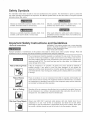
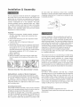
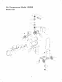
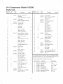
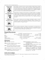
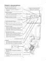
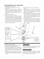
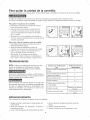
lnstalaci6n
y ensamblaje
con terminal de tierra (ver la figura a continuaci6n).
La
clavija debe enchufarse en un tomacorriente instalado y
puesto a tierra segQn las normas locales. Hable con un
electricista o agente de servicio calificado si no entiende
completamente
estas instrucciones,
o si tiene dudas
sobre la correcta puesta a tierra de la herramienta.
Antes de darle cualquier tipo de mantenimiento al compresor
de aire, se debe apagar y desconectar de la fuente de
alimentaci6n el@ctrica, adem6,s de purgar el aire del tanque
y darle suficiente tiempo para enfriarse. Existe el riesgo
de que las partes m6viles, las fuentes el@ctricas, el aire
comprimido y las superficies calientes provoquen lesiones.
El ensamblaje de conexi6n rapida debe estar instalado
antes de usar el compresor. Un ensamblaje inadecuado
puede set causa de fugas y posiblemente de lesiones.
Si no est,. seguro de entender las instrucciones de
ensamblaje o tiene dificultad para llevar a cabo el armado,
pot favor llame a su departamento local de servicio para
obtener m_s instrucciones.
Tomacorrientes
COlt
Una conexi6n a tierra inadecuada puede provocar una
descarga el@ctrica. Si necesita reparar o cambiar el cable
o la clavija, no conecte el alambre de tierra con ninguna
de las terminales planas. El alambre de tierra es de
color verde, con o sin franjas amarillas. Si no entiende
completamente las instrucciones de conexi6n a tierra,
o si tiene dudas sobre la correcta puesta a tierra de la
herramienta, hable con un electricista o agente de servicio
calificado. No modifique la clavija que viene con el equipol
si no puede enchufarla en el tomacorriente, llame a un
electricista calificado para que le instale el tomacorriente
adecuado.
2. Remueva el tap6n de pl6,stico de la entrada de aire
del compresor. (vet abajo)
8. Instale el filtro dentro de la entrada de aire del
compresor. (yea el diagrama abajo)
4. Remueva el tap6n de llenado de aceite, del c6.rter del
motor y ll@nelo hasta el punto rojo marcado en el vidrio
transparente. La capacidad de aceite es de 90 ml - 3
onzas (vea abajo). Utilice SAE-30 sin detergente (API
CG/CD aceite para motores de gran capacidad). Sobre
condiciones de temperaturas extremosamente frias,
Este producto est,. dise_ado para trabajar en un circuito
con un voltaje nominal de 120 voltios y est,. equipado
en la f_.brica con un cable y clavija que permiten su
conexi6n a un circuito el@trico apropiado. AsegQrese de
que el producto est@ conectado a un tomacorriente con
la misma configuraci6n que la clavija. No se debe usar un
adaptador con este equipo. Si debe conectar el equipo con
un circuito el@trico de diferente tipo, consiga la ayuda de
personal calificado para realizar la reconexi6n.
32 ° F (0°C) o bajo, utilice aceite muy fiuido SAE°10.
5. Coloque nuevamente el tap6n de llenado de aceite.
6. Fije la empu_adura sobre la estructura con los pernos
de cabeza redonda, a partir de la parte exterior de la
empu_adura y los recubrimientos en la parte interior.
Cables de extensi6n
S61o utilice un cable de extensi6n de tres alambres con
de ensambJaje:
5 minutos
una clavija con extensi6n a tierra de tres terminales que
pueda enchufarse en un tomacorriente de tres orificios.
AsegQrese de que su cable de extensi6n est@ en buenas
condiciones. Si utiliza un cable de extensi6n, compruebe
que sea de la capacidad de la corriente que requiere su
equipo. Las extensiones no deben set de mAs de 25 pies
(7,6 m) de largo y deben tenet cable de calibre 12 AWG.
Un cable mAs delgado provocarA una caida en el voltaje
de la linea, Io que provocaria una p@rdida de potencia y
sobrecalentamiento.
Primer paso: Ub[caci6n deJ compresor de[ aire
El compresor del aire siempre debe estar en un medio
ambiente limpio, seco y bien ventilado. La unidad debe
tenet pot Io menos 30 cm de espacio libre en cada lado.
La toma del filtro del aire debe estar limpia y sin ningQn tipo
de obstrucci6n. Pot favor revise diariamente el filtro del aire
para comprobar que est@limpio y funcione correctamente.
lnstrucciones de conexi6n
,a
Terminal de tierra
Ensamb[aje
1. Remueva el compresor de aire, el ensamble de la
empu_adura, la ferreteria, la botella de aceite, el filtro
de aire, el manual y los accesorios de la
Tiempo estimado
aproximadamente
COt?OXi6R
tie rra
a tierra
Este producto se debe conectar a tierra. En el caso de
que haya un cortocircuito, la conexi6n a tierra reduce el
riesgo de descargas el@ctricas al ofrecer una ruta de
escape para la corriente el@ctrica. Este producto cuenta
con un cable que tiene un alambre de tierra y una clavija
Procedimiento
iniciaJ de preparaci6n
No se requiere un procedimiento inicial de preparaci6n.
Este producto ha sido probado en la f_.brica para asegurar
su operaci6n y rendimiento adecuados.
14
Procedim[entos
de operaci6n
Procedirniento diafio de arranque
1. Ponga e[ [nterruptor Auto-On/Off en [a posb[6n de
apagado ( Off).
2. Venfique que e[ compresor de[ aire, [a manguera de
aire y todos bs accesonos/herrambntas ufiHzados, no
tengan da_os n[ obstrucci6n. S[ aigunas de [as pbzas
descritas requbren raparaci6n/reempiazo,
Hame a su
tbnda autorizada bca[ de servicio, antes de usar el
compresor.
3. Cierre [a va[vu[a de drenaje.
4. Revise el hive[ de aceite de [a bomba.
6. Enchufe el cable de corriente en un tomacorriente
apropiado.
7. Mueva el interruptor Auto-On/Off a la posici6n de
encendido (Auto-On); el compresor debera arrancar,
acumulando la presi6n del aire en el tanque hasta
[bgar a [a presi6n de apagado, momento en el cua[ se
apagar6, de manera automatica.
8. Ajuste el regulador a [a presi6n de aire recomendada
(PSi) para su apiicaci6n, cercior_.ndose de que est6
dentro de [as normas de seguridad para [bvar a cabo
[a tarea. Para [as herramientas neum_.ticas, el manual
de[ fabricante debe tener recomendaciones sobre su
5. Enchufe [a manguera de[ aire dentro de[ conector
de acopiamiento r_.pido de [a unidad de[ regulador,
insertando [a davija de conexi6n r6,pida en [a manguera
de[ aire, dentro de[ conector de acopiamiento rapido.
El collarin de[ conector de acopiamiento r_.pido sa[tara
hacia adelante, sujetando [a davija y har6, una junta
entre el conector y [a ciavija. Para desconectar [a
manguera de[ aire, empuje hacia atras el collarin de[
conector de acopiamiento r6,pido.
presi6n de operaci6n (PSi).
9. Ahora el compresor de[ aire esta [isto para set usado.
Los siguientes accesorios de inflado y de [impieza, los
cuabs vienen con esta unidad, s6[o se deben operar a
una presi6n m_xima de 90 PSi: sopbte, boquilla c6nica
de caucho, agujas para infiar, adaptador y adaptador de
sopbte.
Procedimiento
diario de apagado
1. Ponga el interrupter en [a posici6n de apagado (Oft).
2. Desconecte el cable de[ tomacorriente.
3. Ponga en cero el regulador de presi6n de salida.
4. Desconecte [as herramientas y los accesorios. Siempre
use protecci6n para los oidos y los ojos a[ drenar el
tanque. Drene el tanque en un [ugar adecuado; en casi
todos los casos habra presencia de condensaci6n en el
drenaje.
5. Abra [a va[vu[a de drenaje permitiendo que escape el
aire de[ tanque. Cuando haya salido de[ tanque todo el
aire, cierre [a va[vu[a de drenaje para evitar que entre
suciedad.
A[ drenar el tanque utilice protecci6n para oidos y ojos.
Drene el tanque en un [ugar apropiado; en [a mayoria de
[as ocasiones a[ drenar saidr6, condensaci6n.
Si no drena el tanque al almacenarlo, en su interior
quedar_, agua que Io corroera y debilitar6., Io cual puede
provocar su ruptura. Para evitar lesiones graves, drene el
tanque diariamente o despu6s de cada uso.
15
Para quitar Ja unidad de la carretilJa
Para quitaHa, primero ba Uasetapas abajo, antes de intentar quitar o reempUazar eUcompresor de aire de UacarretHUa:
No utilice la carretilla con otros fines que no sean los adecuados para transportar este compresor de aire.
No mueva el ensambb compresor/carretilla sin apretar el pomo que fija con seguridad el compresor sobre la carretilla.
Para quitar eJ compresor de la carretiHa:
1. Debe apagar y desconectar el compresor de aire de la
fuente de aiimentaci6n eI@trica.
2. Gire el pomo que se encuentra en Ia parte inferior de
la carretilla en el sentido contrario del reloi, hasta que
el pomo se desenganche del compresor de aire (D61e
de 1 a 2 vueltas).
3. Manteniendo a Ia vez Ia empdiadura de Ia carretilIa con
una mano, Ievante la empu_adura que se encuentra sobre el
compresor, para quitarlo.
Para volver a fijar ei compresor sobre Ja carretiHa:
1. Debe apagar y desconectar el compresor de aire de la
fuente de alimentaci6n eI@trica.
2. Alinee los bloques de aislamiento de caucho deI
compresor con los huecos de Ia estructura de la carretill&
3. Inserte el pemo con pomo en el compresor de aire y
g(relo en el sentido deI reloj, hasta que est6
bien apretado. (Si el compresor no esta alineado
adecuadamente sobre Ia estructura, no podrb,apretar et
pomo. Vuelva a colocar el compresor y hb.galootra vez.
Mantenimiento
NOTA: Cualquier procedimiento de servicio que no est¢
cubierto en el programa de mantenimiento que sigue
debera set efectuado el personal de servicio calificado.
Asuntos
Antes de dar mantenimiento al equipo, se debe apagar y
desconectar del tomacorriente, asi como purgar el aire del
tanque y permitir que la unidad se enfrie.
A fin de asegurar una operaci6n eficiente y una larga vida
del compresor, debe seguir un programa de mantenimiento
de rutina. El siguiente programa de mantenimiento est_
enfocado al consumidor cuyo compresor es usado en un
medio ambiente normal y diariamente.
para verificar/cambiar
Antes de carla uso
o diariamente
Revisar la valvula de seguridad del
tanque
X
Revisar visualmente el aspecto
general de la unidad
X
Revisar el filtro de aire
X
Drenar el tanque
X
Verificar que el cable el6ctrico
no este daSado
X
Cambiar el aceite
Verificar el nivel del aceite
Despues de las primeras
50 betas
Despu6s de cada 100
horas
Para almacenar el compresor, asegOrese de hacer Io siguiente:
1. Apague la unidad y desconecte el cable el6ctrico del
tomacorriente.
2. Quite del compresor las mangueras, accesorios y
herramientas de aire.
3. Lbve a cabo el programa de mantenimiento de rutina.
4. Abra la v#Jvula de drenaje para drenar el aire del
tanque.
5. Cierre la valvula de drenaje,
6, Guarde el compresor en un lugar limpio y seco,
16
Diagn6stico
y correcci6n
de fallas
Antes de dar mantenimiento al equipo, se debe apagar y desconectar del tomacorriente, asi
como purgar el aire del tanque y permitir que la unidad se enfrie. Las partes en movimiento,
las fuentes el@ctricas, el aire comprimido y las superficies calientes pueden provocar lesiones.
PROBLEMA
POSIBLE CORRECCION
Fuga de aire en la valvula de
Una v6.1vula de retenci6n defectuosa
retenci6n o en la v6.1vulade
v6.1vula de alivio cuando
alivio.
Drene el tanque, quite y limpie o cambie la valvula de retenci6n.
Fugas de aire entre la cabeza
Compruebe que los pemos de la cabeza tengan un par apropiado.
fuga, el cilindro,
llame a un t@nico de servicio.
Fuga de aire en la valvula
Opere manualmente
de seguridad,
teniendo
La presi6n indicada en el
Si al utilizar un accesorio hay una disminuci6n excesiva de presi6n, cambie el regulador.
provoca una fuga de aire constante
est@ apagado
y el compresor
tenga presi6n
en la
de aire.
Si continOa la
la v_.lvula de seguridad jalando el anillo. Si el tanque continOa
una fuga estando
la valvula
en posici6n
cerrada,
deber_
cambiarla.
man6metro de presi6n
regulada bajar_, cuando se
utiliza un accesorio.
Ajuste
la presi6n
regulada
bajo condiciones
de flujo (mientras
accesorio). Es normal que el man6metro indique
minima al comenzar a utilizar la herramienta.
se utiliza
una disminuci6n
un
de presi6n
Presi6n excesiva
Apague el interrupter de encendido (Off). Si la unidad no se apaga, descon@ctela del
en el tanque.
tomacorriente
El motor no arranca.
Compruebe que el cable de corriente est@enchufado y que el interruptor est@encendido
y comuniquese
con un t@cnico de servicio.
Compruebe que el fusible de la caia de circuitos sea de Ia capacidad adecuada.
Si se ha disparado, restabl@zcaloy vueIva a arrancar la unidad. Si el fusible se dispara con
frecuencia, reemplace la valvula de retenci6n o Ilame a un t@nico de servido
Humedad excesiva en el
Saque el agua del tanque dren6.ndolo despu@s de cada vez que se use. En los
aire de salida.
medios ambientes
de alta humedad
habra un exceso de condensaci6nl
instale
filtros de agua en su linea de aire.
La condensaci6n
no es provocada pot una falla en el compresor. Compruebe que la
salida de aire del compresor sea mayor que el consumo del aire de su herramienta.
Fugas de aire en el cuerpo
Nunca
taladre,
o la soldadura del tanque.
debilitara.
suelde
El tanque
o modifique
podria
reparado.
17
de ninguna
romperse
manera
o explotar.
el tanque,
El tanque
pues
no puede
se
set
Your Home
For repair = in your home = of air major brand appliances,
lawn and garden equipment, or heating and cooling systems,
no matter who made it, no matter who sold it!
To purchase a protection
or maintenance agreement (Canada)
1-800-827-6655
(U.S.A.)
Para ped[r serv[c[o de reparac[6n
a dom[c[[[o, y para ordenar p[ezas:
agreement (U.S.A.)
on a product serviced
by Sears:
1o800-361 °6665 (Canada)
Au Canada pour service en fran£a[s:
1-800-LE-FOYER
MC
(1-800-553-6937)
(1 °888°784°6427)
www,sears,ca
¢) Registered Trademark/TM TrademarW s_Service Mark of Sears, Roebuck and Co.
¢) Marca Registrada/TM Marca de F_tbrica/"_Marca
de Servicio de Sears, Roebuck and Co,
lvlc Marque de commerce/UDMarque
depose, e de Sears, Roebuck and Co,
#_ Sears, Roebuck and Co., Sears Canada Inc,