1
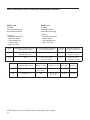
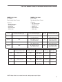
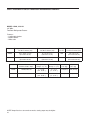
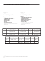
Refrigerators,
Refrigerator-Freezers and Freezers
Explosion-Proof
3551
3551-1
3555
3555-1
3557
3557-2
3557-4
057-196-00 • 2/22/08
Flammable Material Storage
3551-10
3551-11
3556
3556KG
3556-4
3556-4KG
3556-6
Cool-Lab, General Purpose
3750
3761-1
3750-1
3762
3751
3762-1
3751-1
3764A
3752
3764-1A
3753
3770
3753B
3771
3754
3772
3755
3756
3757
3761
Table of Contents
Safety Information ..................................................................................................................................................................3
Alert Signals ....................................................................................................................................................................3
Explosion-Proof Refrigerators and Freezers ..........................................................................................................................4
Overview..........................................................................................................................................................................4
Model 3551, 3551-1 ........................................................................................................................................................5
Model 3555, 3555-1 ........................................................................................................................................................6
Model 3557, 3557-2, 3557-4 ..........................................................................................................................................7
Flammable Materials Storage Refrigerators and Freezers ....................................................................................................8
Overview..........................................................................................................................................................................8
Model 3551-10, 3551-11..................................................................................................................................................9
Model 3556, 3556KG ....................................................................................................................................................10
Model 3556-4, 3556-4KG ..............................................................................................................................................10
Model 3556-6 ................................................................................................................................................................10
Cool Lab, General Purpose Laboratory Refrigerators and Freezers....................................................................................11
Overview ........................................................................................................................................................................11
Model 3570, 3570-1 ......................................................................................................................................................11
Model 3751, 3751-1 ......................................................................................................................................................11
Model 3752....................................................................................................................................................................12
Model 3753, 3753B ......................................................................................................................................................12
Model 3754....................................................................................................................................................................13
Model 3755....................................................................................................................................................................13
Model 3756....................................................................................................................................................................14
Model 3757....................................................................................................................................................................14
Model 3761, 3761-1 ......................................................................................................................................................15
Model 3762, 3762-1 ......................................................................................................................................................15
Model 3764A, 3764-1A..................................................................................................................................................16
Model 3770....................................................................................................................................................................17
Model 3771....................................................................................................................................................................18
Model 3772....................................................................................................................................................................18
Unpacking and Installation ..................................................................................................................................................19
Shipping Carton ............................................................................................................................................................19
Unpacking......................................................................................................................................................................19
Location ........................................................................................................................................................................19
Clearance ......................................................................................................................................................................19
Electrical ........................................................................................................................................................................20
Be Advised ....................................................................................................................................................................20
Sealing Killark Box Conduit to Help Protect Against Explosions ..................................................................................21
Operation ..............................................................................................................................................................................24
Environmental Operating Conditions ............................................................................................................................24
Start-Up Procedure........................................................................................................................................................24
Restart Procedure ........................................................................................................................................................24
Control Panel Lights (Model 3753)................................................................................................................................25
How to Save Energy......................................................................................................................................................26
Safety Tips ....................................................................................................................................................................26
Optional Equipment ..............................................................................................................................................................27
Optional Buzzer Alarm ..................................................................................................................................................27
Troubleshooting ....................................................................................................................................................................29
Maintenance ........................................................................................................................................................................30
Cleaning of Units ..........................................................................................................................................................30
Interior/Exterior and Door Gaskets ........................................................................................................................30
Condenser ..............................................................................................................................................................30
Manual Defrost Procedure (Models 3556-4, 3556-6, 3557-2, 3557-4, 3750, 3750-1, 3752 and 3752-1) ....................31
Manual Defrost Procedure (Model 3772 only) ..............................................................................................................32
Reversing the Front Door (Model 3551)........................................................................................................................33
Reversing the Front Door (Models 3556, 3557 and 3751) ..........................................................................................34
Reversing the Front Door (Models 3772)......................................................................................................................35
Replacement Parts ..............................................................................................................................................................37
Ordering Procedures ............................................................................................................................................................38
Warranty ..............................................................................................................................................................................40
2
Safety Information
Alert Signals
Warning
Warnings alert you to a possibility of
personal injury.
Caution
Cautions alert you to a possibility of
damage to the equipment.
Thank you for selecting Thermo Scientific products for
your equipment needs. These instructions contain important operating and safety information. The user must
carefully read and understand these instructions before
using the unit. Your unit has been designed to optimize
function, reliability, safety and ease of use. It is the userʼs
responsibility to install the bath in conformance with local
electrical codes.
Note
Notes alert you to pertinent facts and
conditions.
Hot Surface
Hot surfaces alert you to a possibility of
personal injury if you come in contact
with a surface during use or for a period
of time after use.
Warning
DANGER: RISK OF CHILD ENTRAPMENT. BEFORE YOU THROW AWAY
YOUR OLD REFRIGERATOR OR
FREEZER:
• TAKE OFF DOORS
• LEAVE THE SHELVES IN
THE PLACE SO THAT
CHILDREN MAY NOT
EASILY CLIMB INSIDE.
3
Explosion-Proof
Refrigerators and Freezers
Overview
Conventional refrigerators and freezers are not only unsuitable for storing flammable materials; they can create potential hazards in a facility. Such units have several components in their electrical and refrigeration systems that can
trigger explosions of flammable air-vapor mixtures inside the
unit or from the immediate surrounding area.
Motors and thermostats are designed to prevent the arcing
that can ignite a flammable air-vapor mixture. In addition,
each unit has wiring, splices, thermostats, relays and compressor motors safely housed within an explosion-proof
enclosure, the construction being suitable for use in Class I,
Groups C and D. This means that things like the surface
temperature of compressors will remain below the flash
point of any flammable material likely to be found in Class I,
Groups C and D locations.
All models have heavy-gauge, rigid, braced-steel construction with a durable enamel finish. Interiors have epoxy
enamel or ABS plastic construction. Each unit is insulated
throughout for energy-efficient operation.
These units will prevent potentially destructive explosions in
any facility by meeting the standards established by
Underwritersʼ Laboratory, Inc., OSHA and National Fire
Protection Association for storage of hazardous materials.
Thermo Scientific Explosion-Proof Refrigerators and
Freezers are 100% explosion-proof. They also meet
National Fire Protection Standards as found in Articles 500501 and provide total protection while storing reagents at or
below ambient temperatures.
4
EXPLOSION-PROOF UNITS
MODEL 3551, 3551-1
23-1/2” Wide,
Two-door Refrigerator/Freezer
Features:
• Overall 11 cu. ft.
• Three adjustable shelves
• Four door shelves
• Hydraulic thermostat
• Adjustable natural air-flow vent
• Manual defrost
• ABS plastic interior
• White color
Model
Refrigerator Chamber Dimensions
H x W x D inches (cm)
Freezer Chamber Dimensions
H x W x D inches (cm)
Total Vol.
Cu. Ft.
Exterior Dimensions
H x W x D inches (cm)
3551-1
39" x 19.5" x 18"
(99 x 50 x 46 cm)
12" x 18" x 16.25"
(30 x 46 x 41 cm)
10.1
60" x 23.5" x 30.5"
(152 x 60 x 77 cm)
3551
39" x 19.5" x 18"
(99 x 50 x 46 cm)
Model
3551
3551-1
12" x 18" x 16.25"
(30 x 46 x 41 cm)
10.1
Electrical Characteristics
Volts/Hz, Watts, Amps
Refrig. Temp.
Range ° C (° F)
Freezer Temp.
Range ° C (° F)
240/50, 360, 1.5
0° to 10°
(32° to 50° )
-20° to 0°
(-4° to 32° )
120/60, 230, 1.9
-1° to 8°
(30° to 46° )
-20° to -12°
(-4° to -10° )
NOTE: Amps listed are at normal run mode, starting amps may be higher.
60" x 23.5" x 30.5"
(152 x 60 x 77 cm)
Net Wt.
Lbs. (kg)
Ship Wt.
Lbs. (kg)
120 (54.5)
150 (68)
120 (54.5)
150 (68)
5
EXPLOSION-PROOF UNITS
MODEL 3555, 3555-1
62” Wide,
Chest freezer
Features:
• Overall 18 cu. ft.
• Key lock
• Storage basket
• Keylock lid
• Manual defrost
• White color
Model
Freezer Chamber Dimensions
H x W x D inches (cm)
Total Vol.
Cu. Ft.
Exterior Dimensions
H x W x D inches (cm)
3555-1
28" x 50.25" x 22.25"
(71 x 128 x 57 cm)
19
35" x 62" x 34"
(89 x 158 x 86 cm)
3555
28" x 50.25" x 22.25"
(71 x 128 x 57 cm)
19
Model
Electrical Characteristics
Volts/Hz, Watts, Amps
Freezer Temp.
Range ° C (° F)
3555-1
240/50, 516, 2.1
-28° to -18°
(-18° to -0° )
3555
120/60, 516, 4.3
-28° to -18°
(-18° to -0° )
NOTE: Amps listed are at normal run mode, starting amps may be higher.
6
35" x 62" x 34"
(89 x 158 x 86 cm)
Net Wt.
Lbs. (kg)
185 (84.1)
185 (84.1)
Ship Wt.
Lbs. (kg)
200 (90.9)
200 (90.9)
EXPLOSION-PROOF UNITS
MODEL 3557
23.5” Wide,
Under counter refrigerator
Features:
• Cold-wall design
• Ample door storage
• Adjustable thermostat
• Rear rollers
• Front legs level-adjust
• Magnetic gasket
• Sturdy metal hinges
• Seamless one-piece
polypropylene liner
• White color
• One glass shelf
MODEL 3557-2
21.25” Wide,
Under-counter freezer
Features:
• Adjustable thermostat
• Magnetic gasket
• Hermetically-sealed compressor
• Off-cycle defrost
• White color
Note (3557)
THIS UNIT IS DESIGNED FOR FREE
STANDING INSTALLATION ONLY. IT
MAY BE INSTALLED UNDER A
COUNTER ONLY IF SUFFICIENT
SPACE FOR AIR FLOW IS PROVIDED. IT IS SUGGESTED THE UNIT
BE RECESSED ONLY 21” TO PERMIT EASY ACCESS TO THE LOCK.
Model
3557
Refrigerator Chamber Dimensions
H x W x D inches (cm)
3557-2
3557-4
27.5" x 19" x 13"
(70 x 48 x 33 cm)
21" x 18" x 15.25"
(53 x 46 x 39 cm)
Model
Electrical Characteristics
Volts/Hz, Watts, Amps
3557-2
120/60, 200, 1.6
3557
3557-4
120/60, 160, 1.3
120/60, 160, 1.3
MODEL 3557-4
21.25” Wide,
Under-counter refrigerator/freezer
Features:
• One-piece seamless interior
• Two rustproof, slide-out shelves
• Adjustable foot
• Drip tray
• Manual defrost
• White color
Note (3557-4)
THIS UNIT IS DESIGNED FOR
FREE STANDING INSTALLATION
ONLY. IT MAY BE ENCLOSED
ONLY IF SUFFICIENT SPACE IS
PROVIDED FOR PROPER VENTILATION. 1” ON THE SIDES, TOP
AND REAR, ARE RECOMMENDED.
Freezer Chamber Dimensions
H x W x D inches (cm)
Total Vol.
Cu. Ft.
Exterior Dimensions
H x W x D inches (cm)
27.25" x 18" x 15"
(70 x 46 x 38 cm)
5.6
33.5" x 21.25" x 29"
(85 x 54 x 74 cm)
5.25" x 15.25" x 11"
(13 x 39 x 28 cm)
Refrig. Temp.
Range ° C (° F)
2° to 7°
(36° to 45° )
-9° to 7°
(15° to 44° )
Freezer Temp.
Range ° C (° F)
-26° to -15°
(-15° to 5° )
-15° to 1°
(5° to 33° )
NOTE: Amps listed are at normal run mode, starting amps may be higher.
5.6
5.6
33.5" x 23.5" x 28"
(85 x 59 x 71 cm)
33.5" x 21.25" x 29"
(85 x 54 x 74 cm)
Net Wt.
Lbs. (kg)
100 (45.3)
100 (45.3)
100 (45.3)
Ship Wt.
Lbs. (kg)
120 (54.5)
120 (54.5)
120 (54.5)
7
Flammable Materials Storage
Refrigerators and Freezers
Overview
These units will prevent potentially destructive explosions
in any facility by meeting the standards established by
Underwritersʼ Laboratory, Inc., OSHA and National Fire
Protection Association for storage of hazardous materials.
They also are designed to comply with National Fire
Protection Association Standards Nos. 45 and 99, as well
as OSHA Article No. CFR1910.308. Thermo Scientific
Flammable Materials Storage Refrigerators/Freezers are
manufactured for safe, cold storage of volatile materials.
Flammable Material Storage (FMS)
Refrigerators/Freezers will prevent an explosion from
occurring inside the unit. These units have no internal
electrical components that could trigger an explosion of
hazardous materials inside the unit. They are NOT
designed for use in Class I, Groups C and D environments. For these locations use a Thermo Scientific
Explosion-Proof Refrigerator. However, FMS units are
not suitable for use in Class I, Group C and D environments.
These units are ideal for storing cyclopropane, ethyl ether,
ethylene, acetone, alcohol, benzene, butane, gasoline,
hexane, lacquer solvent vapors, naphtha, natural gas or
propane along with many other potentially hazardous
materials. All cabinets have heavy-gauge steel construction with a durable exterior finish of epoxy enamel. A well
insulated cabinet and tight sealing magnetic door prevent
air leaks along with helping to lower operating costs. The
interior is made of porcelain-enameled steel or ABS plastic.
8
FLAMMABLE MATERIALS STORAGE UNITS
MODEL 3551-10, 3551-11
23.5” Wide,
Two-door refrigerator/freezer
Note
In order for freezer to reach -20°C,
vent on inside upper rear of refrigerator
must be closed.
Features:
• Overall 11 cu. ft.
• Adjustable thermostat
• ABS plastic interior
• Manual defrost
• White color
Model
Refrigerator Chamber Dimensions
H x W x D inches (cm)
Freezer Chamber Dimensions
H x W x D inches (cm)
Total Vol.
Cu. Ft.
Exterior Dimensions
H x W x D inches (cm)
3551-11
39" x 19.5" x 18"
(140 x 69 x 51 cm)
12" x 18" x 16.25"
(30 x 46 x 41 cm)
10.1
60" x 23.5" x 29.25"
(152 x 60 x 74 cm)
3551-10
39" x 19.5" x 18"
(140 x 69 x 51 cm)
12" x 18" x 16.25"
(30 x 46 x 41 cm)
Model
Electrical Characteristics
Volts/Hz, Watts, Amps
Refrig. Temp.
Range ° C (° F)
Freezer Temp.
Range ° C (° F)
3551-11
240/50, 360, 1.5
-1° to 8°
(30° to 46° )
-20° to -12°
(-4° to -10° )
3551-10
120/60, 230, 1.9
-1° to 8°
(30° to 46° )
-20° to -12°
(-4° to -10° )
NOTE: Amps listed are at normal run mode, starting amps may be higher.
10.1
60" x 23.5" x 29.25"
(152 x 60 x 74 cm)
Net Wt.
Lbs. (kg)
Ship Wt.
Lbs. (kg)
120 (54.5)
150 (68)
120 (54.5)
150 (68)
9
FLAMMABLE MATERIALS STORAGE UNITS
MODEL 3556, 3556KG
23.5” Wide, no-frost
under-counter all refrigerator
with key lock
Features:
• Cold-wall design
• Ample door storage
• Adjustable thermostat
• Rear rollers
• Front legs level-adjust
• Magnetic gasket
• Sturdy metal hinges
• Seamless one-piece
polypropylene liner
• White color
• One glass shelf
MODEL 3556-4, 3556-4KG
21.25” Wide
Front-opening freezer
Features:
• Adjustable thermostat
• Magnetic gasket
• Hermetically-sealed
compressor
• Off cycle defrost
• White color
NOTE (3556): THESE UNITS
ARE DESIGNED FOR FREE
STANDING INSTALLATION
ONLY. THEY MAY BE
INSTALLED UNDER A COUNTER ONLY IF SUFFICIENT
SPACE FOR AIRFLOW IS
PROVIDED. 1” ON THE
SIDES, TOP AND REAR ARE
RECOMMENDED.
Model
3556
Refrigerator Chamber Dimensions
H x W x D inches (cm)
3556-4
3556-6
27.5" x 19" x 13"
(70 x 48 x 33 cm)
21" x 18" x 15.25"
(53 x 46 x 39 cm)
Model
Electrical Characteristics
Volts/Hz, Watts, Amps
3556-4
120/60, 200, .60
3556
3556-6
MODEL 3556-6
21.25” Wide
Refrigerator/freezer
120/60, 160, 1.3
120/60, 160, 1.3
Features:
• One-piece seamless interior
• Two rustproof, slide-out shelves
• Three in-door racks
• Adjustable foot
• Drip tray
• Manual defrost
• White color
NOTE (3556-6): THIS UNIT IS
DESIGNED FOR FREE STANDING
INSTALLATION ONLY. IT MAY BE
ENCLOSED ONLY IF SUFFICIENT
SPACE IS PROVIDED FOR PROPER VENTILATION. 1” ON THE
SIDES, TOP AND REAR ARE RECOMMENDED.
Freezer Chamber Dimensions
H x W x D inches (cm)
Total Vol.
Cu. Ft.
Exterior Dimensions
H x W x D inches (cm)
27.5" x 18" x 15"
(70 x 46 x 38 cm)
5.6
33.5" x 21.25" x 29.25"
(85 x 54 x 74 cm)
5.25" x 15.25" x 11"
(13 x 39 x 28 cm)
Refrig. Temp.
Range ° C (° F)
2° to 7°
(36° to 45° )
-9° to 7°
(15° to 44° )
Freezer Temp.
Range ° C (° F)
-26° to -15°
(-15° to 5° )
-15° to 1°
(5° to 33° )
NOTE: Amps listed are at normal run mode, starting amps may be higher.
10
5.6
5.6
33.5" x 23.5" x 28"
(85 x 59 x 71 cm)
33.5" x 21.25" x 29.25"
(85 x 54 x 74 cm)
Net Wt.
Lbs. (kg)
100 (45.5)
100 (45.5)
100 (45.5)
Ship Wt.
Lbs. (kg)
120 (54.5)
120 (54.5)
120 (54.5)
Cool Lab, General-Purpose
Laboratory Refrigerators/Freezers
MODEL 3750, 3750-1
21.25” Wide,
Refrigerator/freezer
Features:
• One-piece seamless interior
• Two rustproof, slide-out shelves
• Three in-door shelves
• Adjustable foot
• Drip tray
• Manual defrost
• White color
NOTE (3750 and 3751): THESE UNITS ARE
DESIGNED FOR FREE STANDING INSTALLATION ONLY. IT MAY BE INSTALLED
UNDER A COUNTER ONLY IF SUFFICIENT
SPACE FOR AIRFLOW IS PROVIDED.
Overview
These are general-purpose units available in all refrigerator, all freezer and combination refrigerator/freezer models.
MODEL 3751, 3751-1
23.33” Wide,
Under-counter freezer
Features:
• ABS plastic interior
• Four adjustable shelves
• Adjustable thermostat
• Magnetic door gasket
• White color
• Key lock
• One glass shelf
Model
Refrigerator Chamber Dimensions
H x W x D inches (cm)
Freezer Chamber Dimensions
H x W x D inches (cm)
Total Vol.
Cu. Ft.
3750-1
21" x 18" x 15.25"
(53 x 46 x 39 cm)
5.25" x 15.25" x 11"
(13 x 39 x 28 cm)
5.6
33.5" x 21.25" x 25.25"
(85 x 54 x 64 cm)
3751-1
27.5" x 19" x 13"
(70 x 48 x 33 cm)
5.6
33.3" x 23.5" x 24.5"
(85 x 59 x 62 cm)
3750
21" x 18" x 15.25"
(53 x 46 x 39 cm)
3751
27.5" x 19" x 13"
(70 x 48 x 33 cm)
5.25" x 15.25" x 11"
(13 x 39 x 28 cm)
5.6
Model
Electrical Characteristics
Volts/Hz, Watts, Amps
Refrig. Temp.
Range ° C (° F)
Freezer Temp.
Range ° C (° F)
3750-1
240/50, 160, 0.66
2° to 7°
(36° to 44° )
-2° to -6°
(-15° to 21° )
3751-1
240/50, 200, 0.8
2° to 7°
(36° to 44° )
N/A
3750
3751
120/60, 160, 1.3
120/60, 160, 1.3
-9° to 7°
(15° to 44° )
2° to 7°
(36° to 44° )
5.6
-15° to 1°
(5° to 33° )
N/A
Exterior Dimensions
H x W x D inches (cm)
33.5" x 21.25" x 25.25"
(85 x 54 x 64 cm)
33.3" x 23.5" x 24.5"
(85 x 59 x 62 cm)
Net Wt.
Lbs. (kg)
100 (45.4)
100 (45.4)
100 (45.4)
100 (45.4)
Ship Wt.
Lbs. (kg)
120 (54.5)
120 (54.5)
120 (54.5)
120 (54.5)
11
COOL LAB GENERAL-PURPOSE LABORATORY REFRIGERATORS/FREEZERS
MODEL 3752
21.25” Wide,
Under-counter freezer
Features:
• Adjustable thermostat
• Magnetic gasket
• Hermetically-sealed compressor
• Manual defrost
• White color
MODEL 3753, 3753B
24” Wide,
Under-counter freezer
Features:
• Exterior thermostat
• High temperature alarm
• Reversible door
• 3 slide out drawers
• Key lock
• White color
Model
Refrigerator Chamber Dimensions
H x W x D inches (cm)
Freezer Chamber Dimensions
H x W x D inches (cm)
Total Vol.
Cu. Ft.
Exterior Dimensions
H x W x D inches (cm)
3752-1
N/A
27.5" x 18" x 15"
(70 x 46 x 38 cm)
5.6
33.5" x 21.25" x 26"
(85 x 54 x 66 cm)
3752
3752KP
N/A
3753
N/A
27.5" x 18" x 15"
(70 x 46 x 38 cm)
24" x 17.5" x 16"
(61 x 45 x 41 cm)
Model
Electrical Characteristics
Volts/Hz, Watts, Amps
Refrig. Temp.
Range ° C (° F)
Freezer Temp.
Range ° C (° F)
3752-1
240/50, 200, 0.8
N/A
-26° to -15°
(-15° to 5° )
3752
3752KP
3753
120/60, 200, 1.6
240/50, 144, 1.2
N/ A
N/A
4.0
Net Wt.
Lbs. (kg)
33.5" x 21.25" x 26"
(85 x 54 x 66 cm)
34" x 24" x 24"
(86 x 61 x 61 cm)
Ship Wt.
Lbs. (kg)
-26° to -15°
(-15° to 5° )
100 (45.4)
120 (54.5)
-35° to -20°
(-31° to -4° )
100 (45.4)
120 (54.5)
NOTE: Amps listed are at normal run mode, starting amps may be higher.
12
5.6
100 (45.4)
120 (54.5)
COOL LAB GENERAL-PURPOSE LABORATORY REFRIGERATORS/FREEZERS
MODEL 3754
24” Wide,
Front Venting Refrigerator
0 Clearance Front and Sides
Features:
• Automatic cycle defrost
• 2 adjustable shelves
• Built-in or freestanding
MODEL 3755
24” Wide,
Front Venting Freezer
0 Clearance Front and Sides
Features:
• Manual defrost
• 3 shelves
• Reversible door
• Built-in or freestanding
Model
Refrigerator Chamber Dimensions
H x W x D inches (cm)
Freezer Chamber Dimensions
H x W x D inches (cm)
Total Vol.
Cu. Ft.
Exterior Dimensions
H x W x D inches (cm)
3755
N/A
27" x 20.75" x 17.75"
(69 x 53 x 45 cm)
6.0
35.13" x 24" x 23.5"
(89 x 61 x 60 cm)
3754
28" x 21" x 20.75"
(71 x 53 x 53 cm)
N/A
Model
Electrical Characteristics
Volts/Hz, Watts, Amps
Refrig. Temp.
Range ° C (° F)
Freezer Temp.
Range ° C (° F)
3755
120/60, 300, 2.5
N/A
-5° to -20°
(23° to -4° )
3754
115/60, 380, 3.3
1° to 7°
(33° to 45° )
N/A
NOTE: Amps listed are at normal run mode, starting amps may be higher.
6.1
Net Wt.
Lbs. (kg)
100 (45.4)
100 (45.4)
34" x 23.88" x 24"
(86 x 61 x 61 cm)
Ship Wt.
Lbs. (kg)
120 (54.5)
120 (54.5)
13
COOL LAB GENERAL-PURPOSE LABORATORY REFRIGERATORS/FREEZERS
MODEL 3757
20” Wide,
Cube Size Freezer
Reversible Door Swing
MODEL 3756
20” Wide,
Cube Size Refrigerator
Reversible Door Swing
Features:
• Adjustable thermostat
• Manual defrost
• Front-mounted lock
• 100% CFC Free
Features:
• Adjustable thermostat
• Automatic defrost
• Front-mounted lock
• 1 Interior shelf
• 100% CFC Free
Model
Refrigerator Chamber Dimensions
H x W x D inches (cm)
Freezer Chamber Dimensions
H x W x D inches (cm)
Total Vol.
Cu. Ft.
Exterior Dimensions
H x W x D inches (cm)
3757
N/A
15.5" x 14" x 13.5"
(39 x 36 x 34 cm)
1.6
20" x 20" x 21"
(51 x 51 x 53 cm)
3756
15.75" x 15.5" x 12"
(40 x 40 x 30.5 cm)
N/A
Model
Electrical Characteristics
Volts/Hz, Watts, Amps
Refrig. Temp.
Range ° C (° F)
Freezer Temp.
Range ° C (° F)
Net Wt.
Lbs. (kg)
3757
115/60, 83, 1.2
N/A
-20° to -10°
(-4° to 14° )
49 (22)
3756
115/60, 83, 1.2
1° to 7°
(34° to 45° )
N/A
NOTE: Amps listed are at normal run mode, starting amps may be higher.
14
1.8
47 (20)
20" x 20" x 21"
(51 x 51 x 53 cm)
Ship Wt.
Lbs. (kg)
75 (34)
65 (29)
COOL LAB GENERAL-PURPOSE LABORATORY REFRIGERATORS/FREEZERS
MODEL 3761, 3761-1
31.5” Wide,
Top Opening Chest Freezer
Features:
• Key locking cover
• Storage basket
• Keylock lid
• Manual defrost
• White color
MODEL 3762, 3762-1
61.25” Wide,
Top Opening Chest Freezer
Features:
• Key locking cover
• Storage basket
• Keylock lid
• Manual defrost
• White color
Model
Refrigerator Chamber Dimensions
H x W x D inches (cm)
Freezer Chamber Dimensions
H x W x D inches (cm)
Total Vol.
Cu. Ft.
Exterior Dimensions
H x W x D inches (cm)
3761-1
N/A
28" x 26.25" x 16.5"
(71 x 67 x 42 cm)
7.0
35" x 31.5" x 24.5"
(89 x 80 x 62 cm)
3761
3762
3762-1
N/A
N/A
N/A
28" x 26.25" x 16.5"
(71 x 67 x 42 cm)
28" x 50.25" x 22.25"
(71 x 128 x 57 cm)
28" x 50.25" x 22.25"
(71 x 128 x 57 cm)
Model
Electrical Characteristics
Volts/Hz, Watts, Amps
Refrig. Temp.
Range ° C (° F)
Freezer Temp.
Range ° C (° F)
3761-1
240/50, 276, 0.9
N/A
-21° to -4°
(-5° to 24° )
3761
3762
3762-1
120/60, 276, 1.5
120/60, 516, 4.3
240/50, 516, 2.1
N/A
N/ A
N/A
-21° to -4°
(-5° to 24° )
-28° to -18°
(-18° to 0° )
-28° to -18°
(-18° to 0° )
NOTE: Amps listed are at normal run mode, starting amps may be higher.
7.0
19.7
19.7
Net Wt.
Lbs. (kg)
35" x 31.5" x 24.5"
(89 x 80 x 62 cm)
35" x 61.25" x 29.5"
(89 x 156 x 75 cm)
35" x 61.25" x 29.5"
(89 x 156 x 75 cm)
95 (43.2)
95 (43.2)
185 (84.1)
185 (84.1)
Ship Wt.
Lbs. (kg)
125 (56.8)
125 (56.8)
200 (90.9)
200 (90.9)
15
COOL LAB GENERAL-PURPOSE LABORATORY REFRIGERATORS/FREEZERS
MODEL 3764A, 3764-1A
23” Wide,
Two-Door Refrigerator/Freezer
Features:
• 3 adjustable shelves
• Manual defrost
• White color
Model
Refrigerator Chamber Dimensions
H x W x D inches (cm)
Freezer Chamber Dimensions
H x W x D inches (cm)
Total Vol.
Cu. Ft.
Exterior Dimensions
H x W x D inches (cm)
3764-1A
32" x 19.75" x 17.5"
(81 x 50 x 45 cm)
8" x 17.25" x 12"
(20 x 44 x 31 cm)
10.0
58" x 23" x 25"
(147 x 58 x 64 cm)
3764A
32" x 19.75" x 17.5"
(81 x 50 x 45 cm)
8" x 17.25" x 12"
(20 x 44 x 31 cm)
Model
Electrical Characteristics
Volts/Hz, Watts, Amps
Refrig. Temp.
Range ° C (° F)
Freezer Temp.
Range ° C (° F)
3764-1A
240/50, 360, 1.5
1° to 10°
(34° to 50° )
-17° to -6°
(-1° to 21° )
3764A
120/60, 360, 3.0
1° to 10°
(34° to 50° )
-17° to -6°
(-1° to 21° )
NOTE: Amps listed are at normal run mode, starting amps may be higher.
16
10.0
Net Wt.
Lbs. (kg)
120 (54.5)
120 (54.5)
58" x 23" x 25"
(147 x 58 x 64 cm)
Ship Wt.
Lbs. (kg)
150 (68.24)
150 (68.24)
COOL LAB GENERAL-PURPOSE LABORATORY REFRIGERATORS/FREEZERS
MODEL 3770
18.5” Wide,
Benchtop Refrigerator with ice compartment
Note
Model 3770, allow the following
clearance: Top - 12”, Back - 5”,
Sides - 1/2”
Features:
• Overall 1.7 cu. ft.
• Removable shelf
• Manual defrost
• White color
Model
Refrigerator Chamber Dimensions
H x W x D inches (cm)
Freezer Chamber Dimensions
H x W x D inches (cm)
Total Vol.
Cu. Ft.
6” x 6” x 10”
(15 x 16 x 25 cm)
1.7
15” x 16” x 14”
(38 x 41 x 36 cm)
3770
Model
3770
Electrical Characteristics
Volts/Hz, Watts, Amps
120/60, 96, 0.8
Exterior Dimensions
H x W x D inches (cm)
19” x 18.5” x 20”
(48 x 47 x 51 cm)
Refrig. Temp.
Range °C (°F)
Net Wt.
Lbs. (kg)
Ship Wt.
Lbs. (kg)
0° to 7°
(32° to 45°)
35 (16)
40 (18.2)
NOTE: Amps listed are at normal run mode, starting amps may be higher.
17
COOL LAB GENERAL-PURPOSE LABORATORY REFRIGERATORS/FREEZERS
MODEL 3771
24” Wide,
Combination Refrigerator/Freezer
Features:
• 4 adjustable refrigerator shelves
• 2 adjustable freezer shelves
• Automatic defrost
• Reversible doors
• Key lock
• Front mount thermostat
• Designed to fit under overhead counters
• White color
MODEL 3772
23.5” Wide,
Combination Refrigerator/Freezer
Features:
• 4 adjustable refrigerator shelves
• 3 fixed freezer shelves
• Automatic defrost refrigerator
• Manual defrost freezer
• Reversible doors
• 2 independent adjustable thermostat
• 2 independent compressors
• White color
Model
Refrigerator Chamber Dimensions
H x W x D inches (cm)
Freezer Chamber Dimensions
H x W x D inches (cm)
Total Vol.
Cu. Ft.
Exterior Dimensions
H x W x D inches (cm)
3772
35" x 19" x 16"
(89 x 48 x 41 cm)
28" x 17" x 16"
(71 x 43 x 41 cm)
11.8
78.5" x 23.5" x 25"
(199 x 60 x 63 cm)
3771
35.5" x 18.5" x 14"
(90 x 47 x 36 cm)
13" x 18.5" x 10.5"
(33 x 47 x 27 cm)
61" x 24" x 23"
(155 x 61 x 529 cm)
Model
Electrical Characteristics
Volts/Hz, Watts, Amps
Refrig. Temp.
Range ° C (° F)
Freezer Temp.
Range ° C (° F)
Net Wt.
Lbs. (kg)
Ship Wt.
Lbs. (kg)
3772
120/60, 648, 5.4
2° to 7°
(35° to 45° )
-28° to -16°
(-18° to 3° )
192 (87)
202 (92)
3771
120/60, 120, 1.0
-6° to 7°
(21° to 45° )
-20° to -8°
(-4° to 18° )
NOTE: Amps listed are at normal run mode, starting amps may be higher.
18
8.8
160 (73)
Unpacking and Installation
Shipping Carton
This should be inspected upon delivery. When received,
carefully examine for any shipping damage before
unpacking. If damage is discovered, the delivering carrier
should both specify and sign for the damage on your copy
of the delivery receipt.
Open the carton carefully making certain that all parts are
accounted for before packaging materials are discarded.
After unpacking, if damage is found, promptly report it to
the carrier and request a damage inspection promptly.
IMPORTANT: Failure to request an inspection of damage
within a few days after receipt of shipment absolves the
carrier from any liability for damage. You must call for a
damage inspection promptly.
Unpacking
Use the list below when unpacking to verify that the complete unit has been received. Do not discard packing
materials until all is accounted for.
The following items are included in the shipment:
Refrigerator/Freezer
Operation Manual
057-196-00
Volt Warning Tag - 240V
528-609-00
Registration Card
528-022-00
Inspection Tag
528-028-00
Location
Locate your unit in the most convenient place and near a
grounded electric outlet. If units are placed on a countertop, the front should be 3" or more back from the edge to
avoid accidental tipping of the unit.
If possible, locate your unit out of direct sunlight and away
from heat sources such as a radiator, stove or heat duct.
Clearance
Position the unit so that there is at least 12” clearance on
the top, 3” at the back, and 2” on each side. It is recommended that even more space be left at the back of the
unit in case maintenance is required.
19
INSTALLATION
Caution
DO NOT REMOVE, under any circumstance, the grounding prongs
from the 3-prong power cord supplied with all units.
Caution
DO NOT USE electrical extension
cords that may result in voltage loss
and possible hazardous operation.
Caution
Risk of electric shock. (For units
with B, R27 and R30 options.) THis
equipment has two power supply
cords. Unplug all cords before moving or servicing this equipment.
Warning
Explosion-proof units do not come
with line cords. They require rigid
conduit to be run directly in order to
seal off the fitting on thermostat
housing. This should be done by a
licensed electrician and follow all
local and electrician and follow all
local electrical codes. If any questions pertaining to electrical safety
arises, please refer to article 501 of
the National Electrical Code.
Electrical
Units must be connected to a grounded outlet matching
the nameplate and/or the information furnished in this
manual.
If you are not sure about the outlet, you should contact a
qualified electrician for assistance.
The unit should always be connected to its own individual
outlet.
Be Advised
WARNING: UNLESS UNIT IS SPECIFICALLY
DESIGNED FOR COMBUSTIBLE OR FLAMMABLE
ATMOSPHERES DO NOT USE IN THE PRESENCE OF
FLAMMABLE OR COMBUSTIBLE MATERIALS OR
EXPLOSIVE GASES. DO NOT USE IN THE PRESENCE OF PRESSURIZED OR SEALED CONTAINERS—
FIRE OR EXPLOSION MAY RESULT CAUSING DEATH.
CAUTION: BEFORE CONNECTING THE FINAL POWER
SUPPLY, CHECK THE ELECTRICAL CHARACTERISTICS OF THE UNIT NAMEPLATE TO SEE THAT IT IS IN
AGREEMENT WITH THE POWER SUPPLIED. IN ADDITION, POWER SHOULD BE WIRED TO THE UNIT
ACCORDING TO THE ELECTRICAL SCHEMATIC AND
ALL APPLICABLE CODES. ONLY QUALIFIED ELECTRICIANS SHOULD WORK ON THE ELECTRICAL PORTION OF ANY UNIT INSTALLATION.
CAUTION: STORAGE BY USER OF ANY MATERIALS
IN THE PRODUCT THAT MAY CAUSE A DETERIORATION OF THE PRODUCT SHALL BE DEEMED TO CONSTITUTE ABNORMAL AND IMPROPER USAGE OF THE
PRODUCT FOR PURPOSES OF THIS WARRANTY.
WARNING: RISK OF CHILD ENTRAPMENT! Before you
discard your old refrigerator or freezer:
•
•
20
Remove door(s),
Leave the shelves in place so that children may
not easily climb inside.
INSTALLATION
How to Seal Killark® Box Conduit with Fiber and
Sealing Compound to Help Protect Against
Explosions (Explosion-Proof Units Only):
The purpose of the procedure that follows is to build fiber
rope dams on the left and right hubs of the horizontal conduit.
The fiber rope damns will surround conduit wiring that is
housed inside the horizontal conduit.
When both the left and right fiber rope dams have been
pressed into place, sealing compound is poured between the
two and forms into an airtight plug.
All of this is done in order to prevent the very real threat of
gas entering the Killark box and a resulting serious explosion.
After the unit wires have been pulled through the horizontal
conduit the following procedure is required:
•
•
•
•
Turn power off at the circuit breaker before proceeding.
Place a small amount of sealing compound granules, enclosed, into a clean mixing vessel. Add
small amounts of water while stirring until a thick
paste is formed, then carefully continue adding
smaller amounts of water until a thick gravy consistency is achieved—NOT WATERY. Discard any
material that becomes too stiff to use. Never
attempt to restore workability by stirring in more
water.
Locate silver Killark box, back/top-center of unit.
Unscrew conduit domed-cover.
Conduit Domed-Cover
Unscrew and Remove Cover
Conduit Opening
Horizontal Conduit
Left Hub
Right Hub
Figure 1: Sealing the Killark Box
21
INSTALLATION
Figure 2: Horizontal Conduit, Cutaway
Wiring
Left Hub
Right Hub
• Insert fiber rope material down into horizontal conduit opening. Pressing down firmly, work the material into
the left hub and—most importantly—being sure the material COMPLETELY SURROUNDS THE WIRING,
from the top to the bottom, completely blocking this end of the horizontal conduit.
• Insert fiber rope material down into horizontal conduit opening. Pressing down firmly, work the material into
the right hub and—most importantly—being sure the material COMPLETELY SURROUNDS THE WIRING,
from the top to the bottom, completely blocking this end of the horizontal conduit.
22
INSTALLATION
• Pour sealing compound down in between the two fiber rope dams filling the remaining space. Pour slowly,
being careful not to trap air bubbles. Immediately wipe off any spilled sealing compound.
• Screw conduit domed-cover back onto conduit opening.
NOTE: INITIAL SETUP OF SEALING COMPOUND WILL OCCUR IN APPROXIMATELY 30 MINUTES HOWEVER, THE SEALING COMPOUND REQUIRES A MINIMUM OF 8 HOURS ABOVE 32ºF TO DEVELOP
SUFFICIENT STRENGTH TO WITHSTAND EXPLOSIONS.
23
Operation
Environmental Operating Conditions
POLLUTION DEGREE*:
INSTALLATION CATEGORY*:
ALTITUDE:
HUMIDITY:
ELECTRICAL SUPPLY:
VOLTAGE TOLERANCE:
TEMPERATURE:
PRODUCT USAGE:
*Refer to IEC 664-1
2
II
2000 Meters MSL (Mean Sea Level)
80% maximum, non-condensing
120VAC or 240VAC
±10% of normal rated line
15ºC to 40ºC
This product is intended for use indoors only
Start-Up Procedure
Rotate the control knob clockwise to lower the temperature and counterclockwise raise it.
To check chamber temperature, place a dial thermometer
on a shelf in the center of the chamber. Initially, rotate the
temperature control knob to an arbitrary setting. Allow
approximately 2 hours for the temperature to initially stabilize. Check the temperature and compare with the dial
setting.
Adjust dial further to reach the desired operating temperature. After chamber initially stabilizes, allow 1/2 to 1 hour
for the chamber temperature to stabilize after subsequent
temperature adjustments.
Because the markings on the dial do not indicate specific
temperatures, use them AS REFERENCE POINTS ONLY
for any future setting of the temperature.
If the room thermostat is turned below 60ºF at night, consider setting the temperature control one step colder. It
should be left at this setting for the nighttime period;
return temperature control to original setting when the
room thermostat is returned to its normal setting.
Restart Procedure
If unit is unplugged or turned off, allow 3 minutes before
restarting or plugging it back in.
24
OPERATION
Control Panel Lights
(Model 3753)
•
•
2
1
3
Warning Lamp, Top, Red: This light works only
for the freezer compartment. It illuminates when
the temperature decreases from the set point
then turns off when the freezer has achieved set
point again. This lamp will also light when the
unit is turned on and is still at room temperature
and will turn off when the unit begins to cool.
Deep Freezing, Bottom, Yellow: This light will
glow when the thermostat is rotated fully clockwise to “super.” This position keeps the compressor fully on until the normal cycle for the
freezer is turned on. It will get to the low-end
temperature faster until you want to regulate the
temperature. The deep freeze (super) mode
can be kept on at all times if desired.
5
4
3772 Control Panel
6
7
1.
8
2.
3.
4.
5.
6.
7.
8.
WARNING LAMP
POWER INDICATOR (GREEN)
BUTTON FOR DEEP-FREEZING
THERMOMETER FOR THE FREEZING SECTION
LAMP FOR THE REFRIGERATOR SECTION
THERMOSTAT FOR THE FREEZER SECTION
THERMOSTAT FOR THE REFRIGERATOR
SECTION
INDICATOR LAMP FOR DEEP-FREEZING
(YELLOW)
25
OPERATION
How to Save Energy
•
•
•
•
•
•
•
•
Be sure to follow location suggestions as mentioned in the previous INSTALLATION section.
Wipe moisture from glassware or other materials
before placing them in a unit.
Don't overcrowd the unit. Too many items can
increase electrical energy demand in order to
keep everything cool.
Close the door as soon as possible in hot,
humid weather.
Make certain that the door is closed tightly.
As soon as frost has accumulated to 1/4”,
defrost.
Keep containers covered, when possible, to
reduce moisture buildup.
Set operating temperature no colder than necessary for the items being refrigerated.
Safety Tips
•
•
•
26
After a unit is in operation, do not touch the cold
surfaces, particularly when hands are damp.
Skin may adhere to the extremely cold surfaces.
Never disconnect your unit by pulling on the
power cord. Always grip the plug securely and
pull straight out from the outlet.
Do not use a power cord that shows cracks or
abrasions. Have a qualified electrician repair or
replace damaged cords immediately.
Optional Equipment
Optional Buzzer Alarm
ALARM
STATUS LAMP
POWER
6
1
ALARM
DELAY
ADJUST
7
ADJUST
8
2
LOW
ALARM
DISPLAY
HIGH
ALARM
DISPLAY
9
3
10
4
Note
The alarm status lamp (6) will flash
rapidly and the audio will sound in
short pulses during an adjustment.
5
TEMPERATURE DISPLAY (4):
10
Digital devices generally do not round off a reading. In the
case of this temperature monitor, when the display
reports, say a value of 10 degrees, that “10” can represent any temperature from 10.0 to 10.9 degrees.
Therefore, a very small change (0.1 degree or less), or a
minor electronic disturbance many cause the displayed
temperature to change one digit. Only when the displayed
temperature is changing within a period of 20 seconds or
greater can the change be related to real thermal changes
in the space of time being monitored.
READING AND ADJUSTING ALARM POINTS:
To read or set alarm points press the Display button (10)
under the HIGH (3) or LOW ALARM DISPLAY (9) and
while keeping it depressed, turn the adjustment screw(s)
located under ADJUST (2, 8) slowly to set the desired
alarm setpoint. (On dual alarm points, only ONE setting
can be adjusted at a time.)
27
OPTIONAL EQUIPMENT
ALARM CONDITIONS:
•
HIGH SETPOINT ALARM: If the probe temperature exceeds the HIGH setpoint (or falls below
the LOW setpoint on dual setpoint models), the
audio alarm will sound the red ALARM status
lamp (6) will flash.
The unitʼs audio alarm can temporarily be
silenced by depressing the DELAY button (7).
The alarm is shipped set with a 30-minute delay.
During the delay period, the alarm will chirp
about every 30 seconds and the alarm status
lamp (6) to flash during the delay period.
•
If the alarm condition is still present at the end
of the preset 30-minute delay period, the audio
alarm will turn on with full intensity.
LOW TEMPERATURE ALARM (9): This alarm is
triggered by the temperature falling below the
desired setpoint. It is important that this low
alarm point be set at a lower temperature than
the high alarm.
RELAY OUTPUT:
The relay output consists of a SPDT relay that changes
state with a loss of line power OR the presence of an
alarm condition. The contacts are rated at 30V/1Amp.
28
Troubleshooting
In the event that your unit is not operating properly, check the following before calling for service assistance—
this may save you the cost of unnecessary service calls.
Symptom
Unit not operating.
Unit runs continuously.
Possible Cause of Problem
Make certain that the unit is connected to a grounded outlet.
Make certain that temperature control knob is ON.
Check that circuit breaker is not tripped or fuse is not blown.
Make certain that there is no heavy frost accumulation. If there is, defrost
unit.
Look at condenser to see if there is layer of dust or lint. Clean if required
with a dry brush or vacuum.
A leak around the door gasket will allow cold air to escape. This causes unit
to work harder than necessary to maintain cold temperatures. Re-seat or
replace the gasket if worn.
If you have temperature set too cold, this may cause unit to run
continuously. Check optimum running temperature.
Is the ambient air over 43ºC (109ºF), or the units located close to heat
sources? If possible, move to a different location.
Noise problems.
An unusually high frequency of door openings and closings can increase
operating load. Unit will stabilize as these are decreased.
This can be caused by contents of unit being set too close and rattling
against each other. Rearrange contents as needed.
Hissing or gurgling noise is caused by refrigerating fluid circulating and is
normal.
Noise can result if unit is not level on floor. Check with level.
Fan noise: normal airflow can cause this, not a problem.
29
Maintenance
Note
Make no attempt to service or repair
a Thermo Scientific product under
warranty before consulting your
Thermo Scientific dealer. After the
warranty period, such consultation is
still advised, especially when the
repair may be technically sophisticated or difficult. If assistance is needed
beyond what the distributor can provide, please call Customer Service at
800-553-0039. No merchandise
should be returned directly to the factory without obtaining a Return
Materials Authorization (RMA) number from Customer Service.
Warning
Disconnect plug from electrical outlet
before attempting any maintenance
or repair of this unit.
Any internal adjustments or repairs
must be performed by a qualified
service representative.
30
Cleaning of Units
•
•
•
•
Disconnect power cord from its outlet.
Set the temperature control to the OFF position.
The unit designs permit easy and rapid cleaning
and should not take more than a few minutes.
Remember to wear protective gloves to prevent
frost bite, especially when removing items from
freezer units.
Do not use abrasive scouring powders, waxes,
solvents, furniture polish, undiluted detergents or
cleansers containing petroleum products on the
surfaces of units.
Interior/Exterior and Door Gaskets
A solution of mild soap and water can be used for cleaning the interior, exterior and door gaskets with a soft,
clean cloth. Rinse with clean water and dry thoroughly
before reconnecting and turning on the unit.
Condenser
With forced-fan vented units, remove the screws that
mount the grill to the unit. Pull temperature control knobs
straight out. This will expose condenser for cleaning.
MAINTENANCE
Caution
Do not use any sharp instrument,
blade or scraper to remove ice and
frost on refrigerator surfaces
because of the very real danger of
puncturing the cooling coil.
Caution
Do not use any electrical device to
defrost the unit.
When frost accumulates to 1/4" or
more, the operating efficiency of the
unit will be affected.
Manual Defrost Procedure
(Models 3556-4, 3556-6, 3557-2, 3557-4, 3750,
3750-1 and 3752)
Use the following procedure to defrost manually:
•
Rotate the temperature control knob to the OFF
setting.
•
•
•
•
•
•
•
Disconnect the power cord from its outlet.
Remove contents of unit. If practical, wrap contents in paper and then in a heavy blanket to
maintain temperature of items, especially those
removed from a freezer. Wear protective gloves
to prevent frostbite when handling cold items.
Open door and allow free circulation of ambient
air.
To speed the process, place pan of warm water
inside the chamber.
Wipe out the interior.
Replace contents.
Reconnect power cord to outlet and set temperature control to desired operating temperature.
31
MAINTENANCE
Caution
Do not use any sharp instrument,
blade or scraper to remove ice and
frost on refrigerator surfaces
because of the very real danger of
puncturing the cooling coil.
Caution
Do not use any electrical device to
defrost the unit.
When frost accumulates to 1/4" or
more, the operating efficiency of the
unit will be affected.
Manual Defrost Procedure
(Model 3772 Only)
Use the following procedure to defrost manually:
1. Turn the temperature control knob to the 0 setting.
2.
3.
4.
5.
6.
7.
8.
9.
32
Disconnect the power cord from its outlet.
Remove contents of unit. If practical, wrap contents in paper and then in a heavy blanket to
maintain temperature of items, especially those
removed from a freezer. Wear protective gloves
to prevent frostbite when handling cold items.
Open door and allow free circulation of ambient
air.
Fold out the draining spout, mount the enclosed
extension and place a bowl under it.
To speed the process, place a pan of warm
water inside the chamber.
Wipe out the interior when all frozen condensate
has thawed.
Replace contents.
Reconnect power cord to outlet and set temperature control to desired setting.
Model 3772 Illustrating drip pan position
MAINTENANCE
Reversing the Front Door
(Model 3551)
1.
2.
3.
4.
5.
6.
Switch off at the socket outlet and pull out the mains
plug.
Remove all food from the appliance.
Using a cross-headed screwdriver, remove the top
hinge screws.
Remove the top hinge while holding the door.
Lift the door carefully from the lower hinge.
Remove the lower hinge.
7.
Reposition the upper hinge.
9.
Reposition the door hinge bushing and plugs on the
opposite side.
8.
Remove the lower hinge plugs. Remove plugs with
tip of small a screwdriver.
10. Reposition the lower hinge on the opposite side and
fit the hinge washer.
11. Refit the door.
12. Locate the top hinge in the door and loosely attach
to the cabinet.
13. Align the door and then tighten screws firmly on the
top hinge. Check that the door open and closes
easily. Make sure there are no gaps that would
allow air into the cabinet, adjust the top hinge if necessary.
33
MAINTENANCE
Reversing the Front Door
(Model 3556, 3557 and 3751)
1.
2.
3.
4.
5.
6.
7.
8.
9.
Remove bolts and plugs using a screwdriver.
Unscrew the bolts connecting the upper hinges to
the upper platform. Remove the upper platform by
first pulling it forward and then lifting it upwards.
Remove the door by unscrewing the bolts in the
upper hinges.
Remove the buffer by unscrewing the bolts on both
of its sides.
Break off the part behind the buffer through which
the lower hinges pass using a knife or your hands.
Remove the lower hinge and mount it on the other
side tightening its bolts.
Remove the hole plugs of the door handle with a
knife.
Fit the hole plugs of the door handle to the other
side.
Fit the buffer to its place.
10. Mount the door to its place.
11. Fit the upper hinges into their places—do not tighten
the bolts, but leave then loose.
12. Adjust the vertical and parallel position of the door
by eyesight then tighten the bolts of the upper
hinges.
13. Fit the upper platform into its place.
14. Fit the bolts connecting the upper hinges and the
upper platform but, do not tighten them.
15. Adjust the upper platform until it is level, then tighten
the bolts in operations
34
16. Fit the plugs of the upper platform.
MAINTENANCE
Reversing the Front Door
(Model 3772)
1.
2.
Turn thermostats to 0 and disconnect power cords
Remove all items from inside the appliance
3.
Using the proper hex screwdriver, remove the top
hinge screws
4.
Remove the top hinge while holding the door
6.
Remove the middle hinge and lift the lower door off
of pivot
7.
Remove the kick panel. Unscrew nuts and pivot,
remount on the opposite side of the angle iron.
5.
Lift the door carefully from the middle hinge
35
MAINTENANCE
8.
9.
Remove plastic caps on the new middle hinge side.
Remove screw and mount lower door and fasten
middle hinge
Remove the door handle by removing mounting
screws and remount on opposite side
10. Mount the upper door on pivot and fasten the upper
hinge on opposite side then tighten screws
11. For adjustment of doors, loosen screws and reposition door into place and tighten screws
12. Move handle to opposite side of door
36
Replacement Parts
To obtain replacement parts information and pricing,
please call the Customer Service Department at 1-800553-0039 and have the unitʼs model, serial and code
numbers available. This information is located on data
plates on the rear of the unit.
37
Ordering Procedures
Please refer to the Specification Plate for the complete
model number, serial number, and series number when
requesting service, replacement parts or in any correspondence concerning this unit.
All parts listed herein may be ordered from the Thermo
Scientific dealer from whom you purchased this unit or
can be obtained promptly from the factory. When service
or replacement parts are needed we ask that you check
first with your dealer. If the dealer cannot handle your
request, then contact our Customer Service Department
at 563-556-2241 or 800-553-0039.
Prior to returning any materials, please contact our
Customer Service Department for a “Return Materials
Authorization” number (RMA). Material returned without
an RMA number will be refused.
38
39
One Year Limited Warranty
This Thermo Scientific product is warranted to be free of defects in materials and workmanship for one (1)
year from the first to occur of (i) the date the product is sold by the manufacturer or (ii) the date the product is
purchased by the original retail customer (the “Commencement Date”). Except as expressly stated above, the
MANUFACTURER MAKES NO OTHER WARRANTY, EXPRESSED OR IMPLIED, WITH RESPECT TO THE
PRODUCTS AND EXPRESSLY DISCLAIMS ANY AND ALL WARRANTIES, INCLUDING BUT NOT LIMITED
TO, WARRANTIES OF DESIGN, MERCHANT ABILITY AND FITNESS FOR A PARTICULAR PURPOSE.
An authorized representative of the manufacturer must perform all warranty inspections. In the event of a
defect covered by the warranty, we shall, as our sole obligation and exclusive remedy, provide free replacement parts to remedy the defective product. In addition, for products sold within the continental United States
or Canada, the manufacturer shall provide free labor to repair the products with the replacement parts, but
only for a period of ninety (90) days from the Commencement Date.
The warranty provided hereunder shall be null and void and without further force or effect if there is any (i)
repair made to the product by a party other than the manufacturer or its duly authorized service representative, (ii) misuse (including use inconsistent with written operating instructions for the product), mishandling,
contamination, overheating, modification or alteration of the product by any customer or third party or (iii) use
of replacement parts that are obtained from a party who is not an authorized dealer of Thermo Scientific products.
Heating elements, because of their susceptibility to overheating and contamination, must be returned to the
factory and if, upon inspection, it is concluded that failure is due to factors other than excessive high temperature or contamination, the manufacturer will provide warranty replacement. As a condition to the return of any
product, or any constituent part thereof, to the factory, it shall be sent prepaid and a prior written authorization
from the manufacturer assigning a Return Materials Number to the product or part shall be obtained.
IN NO EVENT SHALL THE MANUFACTURER BE LIABLE TO ANY PARTY FOR ANY DIRECT, INDIRECT,
SPECIAL, INCIDENTAL, OR CONSEQUENTIAL DAMAGES, OR FOR ANY DAMAGES RESULTING FROM
LOSS OF USE OR PROFITS, ANTICIPATED OR OTHERWISE, ARISING OUT OF OR IN CONNECTION
WITH THE SALE, USE OR PERFORMANCE OF ANY PRODUCTS, WHETHER SUCH CLAIM IS BASED ON
CONTRACT, TORT (INCLUDING NEGLIGENCE), ANY THEORY OF STRICT LIABILITY OR REGULATORY
ACTION.
For the name of the authorized Thermo Scientific product dealer nearest you or any additional information, contact us:
2555 Kerper Blvd., Dubuque, Iowa, 52004-0797
Phone: 563-556-2241 or 1-800-553-0039
Fax: 563-589-0516
E-mail: [email protected]
Web: www.thermo.com
40