1
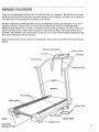
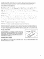
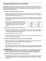
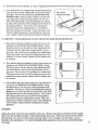
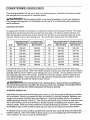
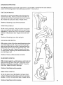
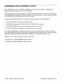
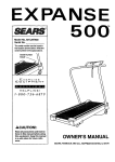
2.0
HP
" 0-70
MPH
z
POWER
ll"4CLINE
. EXPANDED
RUNNING
SURFACE
SF_AIRSo
Model No. 831.297260
Serial No.
The serial number can be found in the
location shown below. Write the serial
number in the space above,
Serial Number
Dec,
.I_ CA UTION!:
Read all safety precautions
and instructions
in this
manual before using this
equipment. Keep this
manual in a safe place for
future reference.
OWNER'S MANUAL
i
i_
,i
FULL 90 DAY WARRANTY
For 90 days from the date of purchase, when proper assembly and maintenance procedures
detailed in the Owner's Manual are followed. SEARS will, free of charge, repair or replace and
install a replacement part for any defective part. when this treadmill is used in a norma! manner,
This warranty does not apply when this treadmill is used for commercial
SERVICE
IS AVAILABLE
CENTER/DEPARTMENT
SIMPLY
BY CONTACTING
IN THE UNITED
YOUR
NEAREST
or rental purposes,
SEARS
SERVICE
STATES.
This warranty gives you specific legal rights, and you may also have other rights which vary
from state to state.
SEARS, ROEBUCK AND CO., DEPT. 817WA,
3333 BEVERLY ROAD, HOFFMAN ESTATES, IL 60179
2
d
2.0
HP
" 0-10
MPH
" POWER
INCLII_4E
. EXPANDED
TABLE
OF CONTENTS
WARRANTY
IMPORTANT
......................................................................
SAFETY PRECAUTIONS
.................................................
RUNNING
SURFACE
2
4
BEFORE YOU BEGIN ..............................................................
ASSEMBLY
......................................................................
OPERATION
AND ADJUSTMENT
.....................................................
TROUBLE-SHOOTING
AND STORAGE
...............................................
CONDITIONING
GUIDELINES
......................................................
PART LIST ......................................................................
EXPLODED
DRAWING
............................................................
ORDERING
REPLACEMENT
IkWARNING:
This is especially
PARTS
5
6
7
10
12
14
15
.........................................
Back Cover
Before beglnnlng thls or any exercise program, consult your physlclan.
Important
for persons
over the age of 35 or persons
with pre-exlstlng
problems.
Read all Instructions
before using. SEARS
assumes no responslbltlty
Injury or property damage sustained
by or through the use of thls product.
health
for persona!
IMPORTANT
SAFETY
kWARNING:
the following
To reduce
Important
PRECAUTIONS
the risk
safety
of burns,
precaut!ons
fire, electric
and Information
shock
before
or Injury
to persons,
operating
read
the treadmill.
1. Posltlon
the treadmill
on a level surface,
wlth at least 8 feet of clearance
behind
the treadmill. Do not place the treadmill
near water, outdoors
or on any surface that blocks an air
opening.
Istered.
Do not operate
where
2. When connecting
the power
plug the power cord dlrectly
aerosol
products
are used
cord (see OPERATION
Into a grounded
circuit
No other appliance
should be on the same circuit.
surfaces,
If an extension
cord Is needed, use only
feet or less In length with a three-wire
conductor.
or where oxygen
AND ADJUSTMENT
capable of carrying
Is being
admin-
In this manual),
12 or more amps.
Keep the power cord away from heated
a 14-gauge general-purpose
cord of five
3. Never move the walking
belt while the power is turned off. Do not operate the treadmill
the power cord or plug Is damaged,
or If the treadmill
Is not working properly.
(See
BEFORE YOU BEGIN In this manual If the treadmill
Is not working
properly.)
4. Wear appropriate
exercise
that could become caught
clothing when using the treadmill; do not wear loose clothing
In the treadmill
Always wear athletic shoes; never use the tread-
mill with bare feet, wearing only stockings
ommended
for both men and women.
5. The pulse earclip
Is not a medical
or In sandals.
device.
Various
Athletic
factors,
support
including
clothes
the user's
whlle exercising,
may affect the accuracy of heart rate readings.
The earcllp
only as an exercise ald In determining
heart rate trends In general.
6. Never start the treadmlll
handrall
when exercising
while you are standing
on the treadmill.
7. Never allow more than one person
used
by persons
weighing
8. Keep small children
unattended
while
more
away from
It Is running.
9. Never drop or Insert any object
10. To reduce the possibility
longer than 1 hour.
If
on the walking
on the treadmill
than
Always
The treadmill
movement
Is Intended
hold the
should
not be
250 pounds.
the treadmill
Always
at a time.
belt.
are rec-
at all times.
Never leave
the treadmill
turn the power off when the treadmill
Is not In use.
Into any opening.
of overheating,
do not operate
11. The treadmill Is capable of hlgh speeds. Adjust
speed.
12.
Use the treadmill
only as described
13.
Always unplug the power cord before
procedures
descrlbed In this manual.
the treadmill
continuously
for
the speed slowly to avoid sudden jumps In
In this manual.
pertormlng the maintenance
and adjustment
Never remove the safety cover unless Instructed
do so by an authorized
servlce representative.
manual should be performed
by an authorized
SAVE THESE iNSTRUCTIONS
Servicing other than the procedures
serllce representative
only.
'
to
In this
BEFORE
YOU BEGIN
Thank you for selecting the SEARS LIFEST'(LER
mill blends advanced technology with innovative
cular exercise
For your
additional
in the convenience
and privacy
_' EXTEND 10.0 treadmill.
The EXTEND 10.0 treaddesign to let you enjoy an excellent form of cardiovas-
of your home.
safety and benefit, read thls manual carefully
before uslng the treadmill.
If you have
questions, please call our Customer Service Department
toll-free at 1-800-999-3756,
Monday through Friday, 6 a.m. until 6 p.m. Mountain Time (excluding holidays).
To help us assist you,
please note the product model number and serial number before calling. The model number of the
treadmill is 831.297260.
The serial number can be found on a decal attached to the treadmill (see the
front cover of this manual for the location).
Before reading further,
labeled.
please
review the drawing
below and familiarize
yourself
with the parts that are
Speed Control
Incline Control
Pulse Earclip .-_
Key/Clip
FRONT
Frame Rails,
Walking
Belt..
_rCord
3ircuit Breaker
BACK
RIGHT
Foot
Rear Roller
Adjustment
Bolts
SIDE
ASSEMBLY
Set the treadmill in a cleared area and remove all packing materials.
Do not dispose of the packing
materials until assembly is completed.
TOOLS REQUIRED
FOR ASSEMBLY:
An 8" adjustable
wrench
_
(not
Included).
1. With the help of a second person, raise the Left Upright
(3) and Right Upright (not shown) to a vertical position.
Align the hole in the lower end of the Left Upright with
the hole in the side of the Left Frame Rail (56). Insert a
3/8" x 4 1/2" Bolt (2), with a Washer (1), into the Left
2
Upright and tighten the Bolt into the Left Frame Rail
Tighten the Bolt that is already in the Left Upright.
Attach a Bolt and Washer on the right side in the same
manner (not shown).
2.
Tighten
58
--
Rotate the Left and Right Handrails (5, 52) up as shown.
Insert two 3/8" x I 1/4" Bolts (7), with Washers (1), into
the Left and Right Uprights (3, 82) and tighten the Bolts.
3. Slide the metal Clothes Clip onto the Pulse Earclip in the
indicated location. The use of the Pulse Earclip is
explained in the MOTIVATIONAL
section on page 9.
FITNESS
3
Pulse Earclip
MONITOR
4. Remove the paper backing from the Wrench Clip (30),
Press the Wrench Clip onto the Right Endcap (78) in the
indicated location. Press the Allen Wrench (14) into the
Wrench Clip,
3O
Make sure that all parts are tightened before using the treadmill.
"--
OPERATION
• PLUGGING
AND ADJUSTMENT
IN THE POWER
CORD
This product
must be grounded,
if it should malfunction or break down, grounding provides a path
of least resistance for electric current to reduce the risk of electric shock. This product is equipped with
a cord having an equipment-grounding
conductor and a grounding plug. Plug the power cord Into an
appropriate
outlet that Is properly
Installed
and grounded
In accordance
with all local codes
and ordinances.
DANGER:
Improper
connection
of the equipment-
1
Grounded
Box
grounding conductor can result in a risk of etectdc shock.
Check with a qualified electrician or serviceman
if you are in
doubt as to whether
the product
is properly
grounded.
Do not
modify the plug provided with the product--if
it will not fit the
outlet, have a proper outlet installed by a qualified electrician.
This product is for use on a nominal 120-volt circuit, and has a
grounding plug that looks like the plug illustrated in Drawing 1.
iGrounding
A temporary adapter that looks like the adapter illustrated in
Drawing 2 may be used to connect this plug to a 2-pole receptacle as shown in Drawing 2 if a properly grounded outlet is
not available.
The temporary adapter should be used only
until a properly grounded
by a qualified electrician.
outlet (Drawing 1) can be installed
The green colored dgid ear, lug, or
Grounded
2._
€_
Pin
Outlet
Grounded
_-JOutlet
Box
the like extending from the adapter must be connected to a
permanent ground such as a properly grounded outlet box
cover. Whenever the adapter is used it must be held in place
by a metal screw.
Some 2-pole receptacle
outlet box covers are not grounded. Contact a qualified
electrician
to determine
If the outlet box cover Is grounded
before using an adapter.
BREAKING
IN THE MAINTENANCE-FREE
WALKING
PLATFORM
Your treadmill features a maintenance-free walking platform with a special hydrocarbon coating. The
walking platform must be broken In completely so the coating Impregnates the walking belt.
Follow the instructions below to break in the walking platform. (See pages 8 and 9 for instructions
about adjusting the speed and incline of the treadmill.)
Adjust the incline of the treadmill to the highest setting. Next, adjust the walking belt to a moderate
speed--about 3 or 4 miles per hour. Hold the handrail and begin walking on the treadmill. Be sure to
step on all areas of the walking belt--not only on the center. While the walking belt is being broken in,
the walking belt may slow or stop as you walk. Continue for 5 to 10 minutes, or until the walking belt
no longer slows as you walk.
IMPORTANT:Never
apply slllcone spray or other substances
to the walklng platform or the
walking belt. Such substances
will deteriorate the walking platform and cause excessive wear.
7
CONSOLEDIAGRAM
Control
Knob
Motivational
Fitness Monitor -[22_
/
Pulse Earclip
INSTALLING
Power
Jack
/
?
Indicator
Inclin
Safety Key!Clip
Control
i_
BATTERIES
Battery
The motivational
fitness monitor
requires
Cover
two "AA= batteries
(not included); alkaline batteries are recommended.
Slide
open the battery cover located on the underside of the console. Grasp the red cord and remove the battery clip from
the console.
Find the markings inside the battery clip showing which direction the batteries should be turned. Press the
batteries into the battery clip. Replace the battery clip in the
console and close the battery cover.
TURNING
THE POWER
@
ON
Step onto the frame rails of the treadmill. Locate the clip attachedby
the clip onto the waistband of your clothing.
CAUTION:
Do not stand on the walking
the clip while operating
switch, Instantly
the treadmill;
turning
the power
a cord to the safety key, and slide
belt while turning
If you fall, the safety
the power
on.
key wtll be pulled from
Always
wear
the power
off.
Insert the safety key into the power switch. The power indicator will light. The five displays of the motivational fitness monitor will not appear until the ON/RESET button is pressed, or the walking belt
begins to move (see CONTROLLING THE SPEED). Note: If batteries were just installed, the five displays will already appear.
CONTROLLING
THE SPEED
To start the walking belt, first turn the speed control knob to "reset."
Then, turn the knob slowly clock-
wise until the walking belt begins to move at slow speed.
CAUTION:
begins
mill.
to move.
After the knob Is turned,
Adjust
the speed
slowly
there will be a pause before
until you are familiar
the walking
with the operation
belt
of the tread-
Carefully step onto the walking belt and begin exercising.
Change the speed of the walking belt as
desired by turning the speed control knob. To stop the walking belt, turn the knob to "reset.'
MOTIVATIONAL
FITNESS
MONITOR
The five displays
of the motivational
plays can be reset by pressing
fitness monitor provide
the ON/RESET
button.
continuous
exercise
The five displays
feedback,
are described
The dis-
below:
TIME--This
display shows the elapsed time. Note: When the walking
will go into a pause mode after a few seconds.
belt is stopped,
CALORIE--This
that you have burned.
display
PULSE--This
display
shows the total number of nutritional
shows
your heart rate.
Calories
Plug the pulse earclip
the TIME
display
into the jack on the console,
and
attach the earclip to your left ear lobe. Slide the metal clothes clip on the earclip wire onto your collar.
After a few seconds, your heart rate will be displayed.
If your heart rate is not displayed after a few
seconds, rub your ear lobe and reposition the earclip, tt may be helpful to stand still while measuring
your heart rate.
SPEED--This
display
DISTANCE--Thls
shows the current speed of the walking
display shows
belt.
the total distance that you have walked
or run.
Note: If the walking belt is stopped and remains stationary for about four minutes, the five displays of
the motivational
fitness monitor will be reset and will darken, although the power will remain on. The
five displays
INCLINE
wi[l appear
again when the ON/RESET
button is pressed,
or the walking belt is restarted.
ADJUSTMENT
Increase
To yary the intensity
mill can be changed
of your exercise,
using the incline
the incline of the treadcontrol on the right side
of the console.
To increase the incline, press the end of the
switch farthest from you. To decrease the incline, press the
end of the switch closest you.
TURNING
OFF THE
POWER
To turn off the power, remove the safety key from the console. The power indicator will darken, Store
the safety key in a secure location.
9
ASSEMBLY
UPDATE
DURING
ASSEMBLY
S_EP
AND ALL-FOtILOWING
Iki_USTRATIONS
_ THE PART'NO.:(49)
<NOB , SHOULD
BE ASSEMBLED
SO _I?"S ON THE LEFT
HAND
SIDE
OF THE UNIT,
IF YOU ARE
SITTING
ON THE UNIT.
ALSO BE SURE
TO ASSEMBLE
THE PART
NO. (63)
_ND(64)
WITH
THE BOLT
PART
NO. (57) FACING
THE
MAIN
POST.
260794
MG/F
._
III
ASSEMBLY
230
.......
UPDATE
)URING
ASSEMBLY
STEP
7, AND
ALL FOLLOWING
ILLUSTRATIONS,
_OB
, SHOULD
BE ASSEMBLED
SO IT"S ON THE LEFT
HAND
SIDE
F YOU ARE SITTING
ON THE
UNIT.
ALSO
BE SURE
TO ASSEMBLE
_D(64)
WITH
THE BOLT
PART
NO. (57) FACING
THE MAIN
POST.
260794
OC:US/12C
THE PART
N0.(49)
OF THE UNIT,
THE PART
N0.(63)
MGIFOCUS/12(_(
TROUBLE-SHOOTING
Most
treadmill
problems
AND STORAGE
can be solved
by following
the simple
steps
below.
that applies to your treadmill and follow the steps listed. If further assistance
Customer Service Department
toll-free at 1-800-999-3756,
Monday through
Mountain "i3me (excluding
holidays).
1. SYMPTOM:
THE
POWER
DOES
NOTTURN
a. Make sure that the power cord is plugged
cord has been plugged
console.
Various
in this manual.)
C.
Check
indicators
the circuit
breaker
into a properly
grounded
outlet.
cord is needed,
in, make sure that the safety
on the console should
located
is needed, please call our
Friday, 6 a.m. until 6 p.m.
ON
AND ADJUSTMENT
in this manual.)
If an extension
al-purpose
cord of five feet or less in length.
b. After the power
Find the symptom
on the treadmill
light.
(See OPERATION
use only a 14-gauge
key is fully inserted
(See OPERATION
gener-
into the
AND ADJUSTMENT
near
the power cord. If the switch protrudes as shown, the
circuit breaker has tripped. To reset the circuit breaker, wait for five minutes and then press the switch
back in.
Tripped
2. SYMPTOM:
THE
a. Check
POWER
the circuit
TURNS
breaker
OFF DURING
located
Reset
USE
on the treadmill
tripped, the switch will protrude.
(See the drawing
five minutes and then press the switch back in.
near the power
above.)
cord.
If the circuit breaker
has
To reset the circuit breaker,
wait for
the safety key fully into the console.
Various
b. Make sure that the power cord is plugged in.
c. Remove the safety key from the console.
indicators on the console should light.
3. SYMPTOM:
THE
PULSE
EARCLIP
Reinsert
DOES NOT FUNCTION
PROPERLY
a. Make sure that the pulse earclip is plugged fully into the jack on the console.
lobe and reposition the earclip. Attach the clothes clip to your collar.
b. Stand
still while measuring
Rub your left ear
your pulse.
c. The pulse earclip may need to be cleaned. Press the earclip open, and find the two clear circles
inside the earclip. Wipe the two clear circles using a cotton swab saturated with denatured alcohol.
,&WARNING:
user's
earcllp
The pulse earclip
movement
while exercising,
is Intended
4. SYMPTOM:
THE
Is not a medical
may affect the accuracy
only as an exercise
WALKING
device.
ald In determining
BELT SLOWS WHEN
WALKED
Various
factors,
Including
of heart rate readlngs.
heart rate trends
the
The
in general.
ON
a. The first time you use the treadmill, walk on the entire surface of the walking belt for 10 minutes
to break in the walking platform.
During this initial break-in pedod, it is normal for the walking
belt to slow.
b. If an extensioncordis needed,useonlya 14-gaugegeneral-purpose
cordoffivefeetor lessin length.
c. If the walkingbelt is overtightenedotreadmillperformance
maydecreaseand the walkingbelt maybe permanently
damaged. Removethe safetykey and UNPLUGTHE
POWERCORD. Usingthe allenwrench,turn both rear
rolleradjustmentboltscounterclockwise,1/4of a turn.
Whenthe walkingbelt is properlytightened,you should
be able to lift eachsideof the walkingbelt3-4 inchesoff
the walkingplatform. The centerof thewalkingbelt
shouldjust touchthe walkingplatform. Be carefulto
keepthe walkingbelt centered. Plugin thepowercord,
insertthe safetykey and runthe treadmillfora few minutes. Repeatuntilthe walkingbelt is properlytightened.
RearRoller
AdjustmentBolts
5. SYMPTOM:THE WALKtNGBELTIS OFF-CENTERORSLIPSWHENWALKED ON
a. If the walkingbelt has shiftedto the left,first removethe
safetykey and UNPLUGTHE POWERCORD. Using
the allen wrench,turn the left rear rolleradjustmentbolt
clockwise,and the right bolt counterclockwise,1/4of a
turn each. Be carefulnot to overtightenthe walkingbelt.
Plugin the power cord, insertthe safetykey andrun the
treadmillfor a few minutes.Repeatuntilthewalkingbelt
is centered.
b. If the walking belt has shifted to the right, first remove the
safety key and UNPLUG THE POWER CORD. Using
the allen wrench, turn the left rear roller adjustment bolt
counterclockwise,
and the right bolt clockwise, 1/4 of a
turn each. Be careful not to overtighten the walking belt.
a
b
L
Plug in the power cord, insert the safety key and run the
treadmill for a few minutes. Repeat until the walking belt
is centered.
c. If the walking
belt slips when walked
on, first remove the
safety key and UNPLUG THE POWER CORD. Using
the allen wrench, turn both rear roller adjustment bolts
C
clockwise, 1/4 of a turn. When the walking belt is correctly
tightened, you should be able to lift each side of the walking belt 3-4 inches off the walking platform. The center of
the walking belt should just touch the walking platform.
Be careful to keep the walking belt centered. Plug in the
power cord, insert the safety key and run the treadmill for
a few minutes. Repeat until the walking belt is properly
tightened.
STORAGE
Unplug the power cord when the treadmill is not in use. Remove the bolts and washers from the upper
ends of the left and right handrails. Rotate the handrails downward. Remove the front bolt and washer
from the lower end of each handrail (see assembly steps 1 and 2 on page 6 for reference). Lay the
handrail on the walking belt. It is recommended that the,!reada3iU be covere d during extended p erigds
of storage.
11
CONDITIONING
The following
and adequate
guidelines
will help you to plan your exercise
rest are essential
, kWARNING:
This Is especially
health problems.
EXERCISE
GUIDELINES
Before
Important
for successful
beglnnlng
program.
that proper
nutrition
results.
this or any exercise
for Individuals
Remember
program,
consult
over the age of 35 or Individuals
your
physician.
wlth pre-exlstlng
INTENSITY
To maximize the benefits of exercising,
it is important to exercise with the proper intensity.
The proper
intensity level can be found by using your heart rate as a guide. For effective aerobic exercise, your
heart rate should be maintained at a level between 70% and 85% of your maximum heart rate as you
exercise.
This is known as your training zone. You can find your training zone in the table below.
UNCONDITIONED
TRAINING
ZONE
(B EATSIMIN)
CONDITIONED
TRAINING
ZONE
(BEATSfMIN)
127-155
122-149
60
126-153
121-147
130-158
65
125-151
119-145
134-162
129-156
70
123-150
118-144
40
132-161
127-155
75
122-147
117-142
45
131-159
125-153
8O
120-146
115-140
50
129-156
124-150
85
118-144
114-139
AGE
UNCONDITIONED
TRAINING
ZONE
(BEATS/MIN)
CONDITIONED
TRAINING
ZONE
(BEATS/MIN)
20
138-167
133-162
25
136-166
132-160
30
135-164
35
AGE
During the first few months of your exercise program, keep your heart rate near the low end of your
training zone as you exercise. After a few months of regular exercise, your heart rate can be increased
gradually until it is near the middle of your training zone as you exercise.
You can measure your heart
rate using the pulse mode of the console,
Exercise for at least four minutes, and then measure your
heart rate immediately.
If your heart rate is too high, decrease the intensity of your exercise.
If your
heart rate is too low, increase
kWARNING:
the intensity
The pulse earcllp
of your exercise.
Is not a medical
"
device.
Various
factors,
movement during exercise, may affect the accuracy of heart rate readings,
ed only as an exerclse aid In determining
heart rate trends In general.
WORKOUT
Including
The earcllp
your
Is Intend-
GUIDELINES
Each workout should consist of three basic parts: a warm-up, 20 to 30 minutes of training zone exercise,
and a cool-down. Warming up prepares the body for exercise by increasing circulation, delivedng more
oxygen to the muscles and raising the body temperature. Begin each workout with 5 to 10 minutes of
stretching and light exercise to warm up. Then, increase the intensity of your exercise to raise your heart
rate to your training zone for 20 to 30 minutes. Breathe regularly and deeply as you exercise--never
hold your breath. Finish each workout with 5 to 10 minutes of stretching to cool down. This will increase
the flexibility of your muscles as well as he!p to decrease soreness and other post-exercise problems.
To maintain or improve your cond tion; comp ere three workouts each week, with at least one day of lest ....
between Workouts. After _fe_ m0nt_sof
_'eguial: exercise, you may compleie up tof ,_e_w0rkouts'each ".
week, if desired.
The key to success
is CONSISTENCY.
SUGGESTED
STRETCHES
The following stretches can provide a good warm-up or cool-down.
Correct
shown in the drawings below. Move slowly as you stretch--never
bounce.
form for each stretch
is
TOETOUCHSTRETCH
Stand with your knees bent slightly and slowly bend forward from your hips. Allow your back and shoulders to
relax as you reach down toward your toes as far as possible. Hold for t5 counts, then relax. Repeat 3 times.
Stretches:
Hamstrings,
HAMSTRING
back of knees and back.
STRETCH
Sit with one leg extended.
Bring the sole of the opposite
foot toward you and rest it against the inner thigh of your
extended leg. Reach toward your toes as far as possible.
Hold for 15 counts, then relax. Repeat 3 times for both
legs.
Stretches:
Hamstrings,
CALF/ACHILLES
With
your
and
lean
lower back and groin.
STRETCH
one leg in front of the other, reach forward and place
hands against a wall. Keep your back leg straight
your back foot flat on the floor. Bend your front leg,
forward and move your hips toward the wall. Hold
for 15 counts, then relax. Repeat 3 times for both legs.
To cause further stretching of the achilles tendons, bend
your back leg as well.
Stretches:
Calves,
achilles
tendons
and ankles.
QUADRICEPSSTRETCH
With one hand against a wall for balance, reach back and
grasp one foot with your other hand. Bring your heel as
close to your buttocks as possible, Hold for 15 counts,
then relax, Repeat 3 times for both legs.
Stretches: Quadriceps and hip muscles.
INNER THIGH STRETCH
Sit with the soles of your feet together and your knees
outward. Pull your feet toward your groin area as far as
possible. Hold for 15 counts, then relax. Repeat 3 times.
Stretches!
QUad}icepS
and hip muscles:
13
PART LlSTmModel
14
Key
No.
Part
No.
Qty.
1
2
014086
013485
8
4
3
4
5
115534
114005
115816
6
7
8
No. 831.297260
Rev.12/93
Key
No.
Part
No.
Qty.
Upright Washer
3/8" x 4 1/2" Bolt
45
46
115404
111680
2
1
Reinforcement
Plate
Reed Switch Clip
1
2
1
Left Upright
Handrail Endcap
Left Handrail
47
48
49
115683
113601
113603
1
2
1
Right Frame Rail
Rear Roller Insert
Right Front Holler Insert
105477
114489
109788
16
4
1
Flange Nut
3/8" x 1 1/4" Bolt
Rear Holler
50
51
52
113287
014066
115817
1
2
1
Left Front Roller
Lock Washer
Right Handrail
53
033066
1
Magnet
54
55
012108
115523
6
1
Nut
Incline
Descrlption
Descrtptlon
Insert
9
106939
1
MotorBelt
10
11
112589
115811
1
1
Pulse Earclip/Clothes
Console
12
13
14
110000
115856
045010
1
1
1
Speed Control Knob
PowerWire
Hamess
Allen Wrench
56
57
58
115682
013369
013211
1
2
14
Left Frame Rail
Incline Bolt
Motor Frame Bolt
15
16
114265
103053
1
Safety Key/Clip
Motor Bolt
59
60
115333
115857
1
1
Incline Leg
Manual Lift Wire Hamess
17
18
19
113278
012082
014041
1
5
2
PulleylFlywheel/Fan
Tension Nut/Spring
Tension Washer
61
62
63
052014
013399
031229
2
4
1
Wheel
Wheel
Power
20
21
22
23
104514
103855
116455
013303
1
1
1
2
Tension Spring
J-Bolt
Switch Bezel
Motor Swivel Bo_t
64
65
66
67
013547
019084
115328
113985
2
1
1
2
Incline Leg Bolt
Grommet
Motor Frame
Cushion Cover
24
25
031108
109365
1
1
Incline Switch
Choke
68
69
111869
109265
8
2
Cage Nut
Belt Guide
26
27
28
113185
113264
113184
1
1
1
Right Front Endcap
Left Upright Spacer
Front Left Endcap
70
71
72
115689
108080
115684
1
31
1
Front Ro[ledPulley
Small Screw
Walking Platform
29
30
31
32
33
110447
016028
115814
115813
116192
1
1
1
1
1
_
Wrench Clip
Motor
Motor Swivel Shaft
Reed Wire Extension
73
74
75
76
77
115691
115532
115326
013162
110926
1
1
1
18
4
Front Safety Cover w/Decal
Rear Safety Cover
Cushion Spring Crossbar
Screw
Cushion Spring Bolt
34
35
36
115688
015071
111205
1
4
1
Walking Belt
PlasticStand-Off
Incline Board
78
79
80
113183
013300
115032
1
3
2
Right Rear Endcap
Endcap Screw
Cushion Spring Foot
37
38
39
40
41
108973
113964
105444
014127
113182
1
1
1
3
1
Mounting Plate
Reed Switch Bracket
Front Roller Adj. Bolt
Adjustment Washer
Left Rear Endcap
81
82
83
84
85
013206
115646
115293
114001
116091
2
1
1
1
1
Rear Holler Adj. Bolt
Right Upright
Choke Plate
Console Plate
Front Cover Plate
42
43
44
113265
109382
115571
1
1
1
Right Handrail Spacer
Circuit Breaker
Reed Switch/Sensor
Wire
86
87
#
116092
116427
115562
1
1
1
Rear Cover Plate
Controller
Plate
Owner's Manual
Note: "#, ndlcates a non' Ilustrated pa_.
back cover for information about ordering
Clip
Foot Nut
SpecifiCations are subject
replacement parts.
to change
Motor
Bolt/Console
Cord
without
notice.
Bolt
See the
EXPLODED
DRAWING--Model
No. 831.297260
Rev.iz_93
11_
16
12
15
22
,-24
68
31
_7
23
38 71
51
2O
7
83
71
25
28
27
71
36
.,_
I
I
70
I
i
71
68
72
\
56
i 49
i
39
69
4O
73
74
\
I
41
48
i
47
76
71
6
14
55
/,
76
61
62
66
57
15
ORDERING
REPLACEMENT
PARTS
Each TREADMILL
has its own MODEL
requesting
or repair parts for your TREADMILL.
service
NUMBER.
Always
mention
All parts listed herein can be ordered through SEARS, ROEBUCK
most SEARS RETAIL STORES. tf parts you need are not stocked
to a SEARS PARTS DISTRIBUTION
CENTER for handling.
WHEN
ORDERING
1. The MODEL
2. The NAME
REPAIR
NUMBER
4. The DESCRIPTION
ALWAYS
of the product
of the product
9. The PART NUMBER
PARTS,
(SEARS
this MODEL
INFORMATION:
(831.297260).
LIFESTYLER
_ EXTEND
10.0 treadmil0.
of the part(s) from page 14 of this owner's
manual.
manual.
Your SEARS TREADMILL
has added value when you consider that SEARS
wide, staffed with SEARS trained technicians
specifically trained on SEARS
tools and equipment
to ensure that we meet our pledge to you: "We service
Should you ever need repair service
or pads, call toll fr,ee:
For repair service:
(1-800-473-7247)
For repair parts:
Part NO. 115562
1--800-FON-PART
when
AND CO. SERVICE CENTERS and
locally, your order will be transmitted
GIVE THE FOLLOWING
of the part(s) from page 14 of this owner's
1-800-4-REPAIR
NUMBER
has service units nationproducts, having the parts,
what we sell."
(1-800-366-7278)
12/93 Printed in USA
© 1993 Sears,
Roebuck
and Co.