1
LBI-38836B
Maintenance Manual
DUAL FORMAT PCS
800 MHz PORTABLE RADIO
COMBINATION
TABLE OF CONTENTS
FRONT ASSEMBLY ..................................................................... LBI-38855
REAR ASSEMBLY........................................................................ LBI-38856
.......................................................................LBI-39180
SERVICE SECTION...................................................................... LBI-38857
ERICSSONZ
LBI-38836B
NOTICE!
This manual covers Ericsson and General Electric products manufactured and sold by Ericsson Inc.
NOTICE!
Repairs to this equipment should be made only by an authorized service technician or facility designated by the supplier.
Any repairs, alterations or substitution of recommended parts made by the user to this equipment not approved by the
manufacturer could void the user’s authority to operate the equipment in addition to the manufacturer’s warranty.
NOTICE!
The software contained in this device is copyrighted by the Ericsson Inc. Unpublished rights are reserved under the
copyright laws of the United States.
This manual is published by Ericsson Inc., without any warranty. Improvements and changes to this manual necessitated
by typographical errors, inaccuracies of current information, or improvements to programs and/or equipment, may be made
by Ericsson Inc., at any time and without notice. Such changes will be incorporated into new editions of this manual. No
part of this manual may be reproduced or transmitted in any form or by any means, electronic or mechanical, including
photocopying and recording, for any purpose, without the express written permission of Ericsson Inc.
Copyright© January 1993, Ericsson GE Mobile Communications Inc.
2
LBI-38836B
TABLE OF CONTENTS
Page
SPECIFICATIONS.......................................................................................................................................
GENERAL ............................................................................................................................................
TRANSMITTER...................................................................................................................................
RECEIVER ...........................................................................................................................................
OPTIONS AND ACCESSORIES ...............................................................................................................
DUAL FORMAT PCS RADIO PACKAGE NUMBERS ..........................................................................
INTRODUCTION........................................................................................................................................
DESCRIPTION.....................................................................................................................................
FEATURES...................................................................................................................................................
STANDARD RADIO FEATURES ......................................................................................................
CONVENTIONAL MODE FEATURES.............................................................................................
TRUNKED FEATURES (EDACS®/GE-MARC)..............................................................................
EDACS (ONLY) FEATURES..............................................................................................................
GE-MARC (ONLY) FEATURES ........................................................................................................
OPERATION ................................................................................................................................................
CONTROLS..........................................................................................................................................
INDICATORS .......................................................................................................................................
BATTERY PACKS .......................................................................................................................................
INSTALLING THE BATTERY PACK................................................................................................
REMOVING THE BATTERY PACK..................................................................................................
CHARGING THE BATTERY PACKS................................................................................................
CHANNEL GUARD ENCODE/DECODE.........................................................................................
EDACS SYSTEM DESCRIPTION ............................................................................................................
GE-MARC SYSTEM DESCRIPTION.......................................................................................................
ORIGINATING A CALL .....................................................................................................................
OPERATIONAL MODES....................................................................................................................
READY MODE ...................................................................................................................................
4
4
5
5
6
7
8
8
8
8
8
10
10
11
11
11
12
13
13
13
14
14
15
15
17
17
18
FIGURES
Figure 1 - Dual Format PCS Radio (SCAN) ..............................................................................................
Figure 2 - Dual Format PCS Radio (SYSTEM) .........................................................................................
Figure 3 - Dual Format PCS Display ..........................................................................................................
Figure 4 - Installing the Battery Pack .........................................................................................................
Figure 5 - Removing The Battery Pack.......................................................................................................
Figure 6 - Operational Modes......................................................................................................................
Figure 7 - Tone Signal Timing.....................................................................................................................
Figure 8 - Idle Mode ....................................................................................................................................
Figure 9 - Wait Mode ...................................................................................................................................
Figure 10 - Ready Mode ..............................................................................................................................
9
9
12
13
13
17
19
19
20
21
TABLES
Table 1 - CG Tone Frequencies ...................................................................................................................
Table 2 - Primary & Equivalent Digital Codes (OCTAL) .........................................................................
14
16
3
LBI-38836B
SPECIFICATIONS
GENERAL
Dimensions (Less Antenna) H x W x D
With 1200 maH Battery
With 1700 maH Battery
8.4 x 2.8 x 1.77 inches
21.3 x 7.2 x 4.5 centimeters
Weight
Radio (less battery)
1200 mAH Battery
1700 mAH Battery
14 oz
9 oz
13.5 oz
Ambient Temperature Range
-30 to 60 °C (-22 to 140 °F)
Vibration
EIA/USFS/MIL-STD-810E, METHOD 514.4
PROCEDURE 1
Shock
EIA/MIL-STD-810E, METHOD 516.4,
PROCEDURE 1,4
Relative Humidity
EIA/MIL-STD-810E, METHOD 507.3, PROCEDURE 2
Altitude
15000 Feet
Construction
Front
Rear
Lexan Polycarbonate
Die-Cast Aluminum
Battery Drain
Receive Standby
Receive Full Audio
Transmit at 3 Watts
Transmit at 1 Watt
90 mA
270 mA
2.0 A
1.3 A
Battery Life (Between Charges)
1200 mAH Battery
HI Power
LO Power
6.5 Hours
8.0 Hours
1700 mAH Battery
HI Power
LO Power
Regulatory Approval
FCC (USA)
DOT (Canada)
4
7.1 x 2.8 x 1.77 inches
17.8 x 7.2 x 4.5 centimeters
9.2 Hours
11.3 Hours
AXA9MX-PCS8
PCS8
LBI-38836B
SPECIFICATIONS (CON’T)
TRANSMITTER
Frequency Range
Talk Around
Power Output
HI Power
LO Power
806-824 MHz
851-869 MHz
3 Watts (806-824 MHz)
2.2 Watts (866-870 MHz)
2.5 Watts (851-866 MHz)
1 Watt (806-869 MHz)
Frequency Stability
NPSPAC
±1.5 ppm
Conducted Spurious
-65 dB (-30 dBm)
Radiated Spurious
-65 dB (-30 dBm)
Deviation
5 kHz
4 kHz (NPSPAC)
Audio Response
EIA
Hum And Noise
-40 dB
Audio Distortion
5% (max)
RECEIVER
Frequency Range
851-870 MHz
Audio Output
.5 Watt
Sensitivity
-116 dBm (.35 µV)
Frequency Stability
NPSPAC
1.5 ppm
Selectivity
-65 dB @ 25 kHz
-20 dB NPSPAC
Intermodualtion
-65 dB
Spurious Response
-60 dB
Audio Frequency Response
EIA
Hum And Noise
-40 dB (max)
Conducted Spurious Response
Canada
-47 dBm
5
LBI-38836B
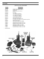
OPTIONS AND ACCESSORIES
OPTION #
PCAC1C
PCAC1D
PCAE1F*
PCZM1A*
PCHC1C*
PCHC1D*
PCHC1A*
PCHC1B
PCHC3E
PCHC3F
PCNC3L*
PCPA1J*
PCPA1K*
PCPA1L
PCPS1K
CH1SS1*
CH1SS2
CH1RS1*
CH1RS2
CH6SS1
CH6SS2
CH6RS1
CH6RS2
*
6
Pictured below.
DESCRIPTION
Earphone UDC Connector Only
Earphone Without UDC Connector
Speaker MIC
Earphone With UDC Connector
Belt Clip
Swivel Plate
Case With Top Short Battery
Case With Strap Short Battery
Case With Top Long Battery
Case With Strap Long Battery
Antenna Whip 806-870 MHz
High Capacity Battery Pack
Extra High Capacity Battery Pack
Extra High Capacity Battery Pack (FM Intrinsically Safe)
Mobile Charger (Sleeve)
Desk Charger 50/60Hz, 120V, 14HR
Desk Charger 50/60Hz, 230V, 14HR
Rapid Desk Charger 50/60Hz, 120V, 1HR
Rapid Desk Charger 50/60Hz, 230V, 1HR
Multicharger 50/60Hz, 120V, 14HR
Multicharger 50/60Hz, 230V, 14HR
Rapid Multicharger 50/60Hz, 120V, 1HR
Rapid Multicharger 50/60Hz, 230V, 1HR
LBI-38836B
DUAL FORMAT PCS RADIO PACKAGE NUMBERS
Package Number
Description
PC8LGS
PC8LGD
PC8MGS
PC8MGD
PC8TGS
PC8TGD
800 MHz DUAL FORMAT 9 SYS/GROUPS (SCAN, EGE)
800 MHz DUAL FORMAT 9 SYS/GROUPS (SYSTEM, EGE)
800 MHz DUAL FORMAT 128 SYS/GROUPS (SCAN, EGE)
800 MHz DUAL FORMAT 128 SYS/GROUPS (SYSTEM, EGE)
800 MHz DUAL FORMAT 625 SYS/GROUPS (SCAN, EGE)
800 MHz DUAL FORMAT 625 SYS/GROUPS (SYSTEM, EGE)
PC8LES
PC8LED
PC8MES
PC8MED
PC8TES
PC8TED
800 MHz DUAL FORMAT 9 SYS/GROUPS (SCAN, ERIC)
800 MHz DUAL FORMAT 9 SYS/GROUPS (SYSTEM, ERIC)
800 MHz DUAL FORMAT 128 SYS/GROUPS (SCAN, ERIC)
800 MHz DUAL FORMAT 128 SYS/GROUPS (SYSTEM, ERIC)
800 MHz DUAL FORMAT 625 SYS/GROUPS (SCAN, ERIC)
800 MHz DUAL FORMAT 625 SYS/GROUPS (SYSTEM, ERIC)
7
LBI-38836B
INTRODUCTION
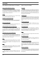
The Ericsson GE Dual Format PCS Personal radio is a
rugged, lightweight unit which is housed in a molded Lexan
Front assembly and an Aluminum Rear casting. The new
PCS radio provides reliable service in the 800 MHz band and
contains new DUAL FORMAT technology that enables the
radio to operate within a GE-MARC trunked system and an
EDACS trunked system. There are two models available, the
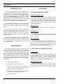
3-button SCAN model and the system model (which contains a DTMF keypad and supports DTMF operation).
The radio normally transmit in the 806-825 MHz band
and receives from 851-870 MHz. The radio is able to transmit from 851-870 MHz for Talk-Around in the GE-MARC
system.
The Dual Format PCS radio is offered with several
packages available with respect to the number of systems/groups programmed and the EDACS feature set allowed. The radio is also capable of Conventional operation.
See the section on page 6 for a complete description of the
Packages available.
The radio is programmed using a Personal Computer
and an Interface Box connected to the UDC connector on the
side of the radio. This allows the radio to be tailored to meet
the requirements of the individual user and of the System(s)
it is operating within.
DESCRIPTION
The radio is made up of the front assembly, the rear
assembly and the control frame assembly. The RF Board is
housed in the Rear Assembly and contains all transmit,
receive and synthesizer circuits. The Oscillator stability and
Receiver selectivity meets NPSPAC specifications. The
Audio Logic Board is housed in the Front assembly and
contains all transmit audio and receive audio circuits along
with all logic and control circuits. The Control Frame assembly mounts in the radio front cover and provides the following functions:
•
•
•
•
•
8
Audio Logic board interface
Microphone and speaker connections
Houses the Select buttons for selecting Systems/Groups, the Volume up/down buttons, the
SHFT/CLR button and the PTT button
UDC interface to the outside of the radio for external options and customer programming
Liquid Crystal Display
FEATURES
STANDARD RADIO FEATURES
Carrier Control Timer (CCT)
The CCT is programmable on a per channel basis and
prevents unnecessary channel traffic and radio damage if the
transmit timer is exceeded. If the programmed timer times
out during a transmission the radio will beep and stop transmitting. The beeping tone will continue until the operator
released the PTT Button.
Audio Alert Beeps
The PCS radio generates a number of alert tones to
indicate various events.
Low Battery Alert
When the battery is low and needs to be recharged, the
BT icon will be displayed and a low pitch tone will sound
every 130 seconds.
Power Up Self Test
Each time the radio is turned on it will perform a powerup self test. After successful completion of the test, an
optional tone will sound and the current System and
Group/Channel will be displayed. If the unit does not pass
the self test an error message will be displayed.
CONVENTIONAL MODE FEATURES
Channel Guard
Channel Guard provides a means of restricting calls to
specific radios through the use of a Continuous Tone Coded
Squelch System (CTCSS), or a multi-code Digital Squelch
System (DCG). Tone frequencies range from 67 Hz to 210.7
Hz. There are 83 standard programmable digital codes.
Manual DTMF Operation
Telephone interconnect calls can be made using the
12-button keypad. This keypad is enabled when a DTMF
programmed channel is selected and PTT Button is pressed.
LBI-38836B
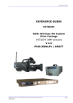
Figure 1 - Dual Format PCS Radio (SCAN)
Figure 2 - Dual Format PCS Radio (SYSTEM)
9
LBI-38836B
TRUNKED FEATURES (EDACS/GE-MARC)
EDACS (Only) FEATURES
Preprogrammed DIG/DTMF Numbers
Group Scan
During the PC programming of the radio, the special call
list may be programmed with up to 96 numbers for EDACS
and 96 numbers for GE-MARC, depending upon available
personality space. Using the SPC key, the numbers can be
recalled to initiate the special call.
The radio monitors the control channel and responds to
all group channel assignments associated with the "scan" list.
The "priority" group is dictated by the group currently selected. If a call occurs on the "priority" group while monitoring on of the scan groups, the radio will immediately late
enter into the "priority" group.
HOME
Automatic Login
The radio will automatically select a desired Group
and/or System by depressing a single key.
Keypad Lock (System Model Only)
To prevent undesired key presses, the keypad can be
locked at any time by depressing the LOCK key (shift 0).
The radio automatically transmits the "Login" message
when the radio roams into a new system, when changing the
group selector and when the radio is turned on. The "Login"
message includes the Logical ID and the Group ID for the
radio.
System/Group Selections
Power Up System/Group
The unit can be PC programmed to automatically select
a desired Group and/or System on power up.
The standard EDACS feature set allows up to 16 systems total, plus group selections. 128 and 625 selection
features are also available.
Manual Individual Calls (System Model Only)
Conventional Failsoft
The System Model radio is capable of making Individual calls which are not programmed into your radio. The
Individual Calls are made by manually entering the ID number (EDACS) or Tone Set (GE-MARC) from the radio keypad.
In the unlikely event of a trunking failure, communications may take place in the Conventional Failsoft mode. The
radio will automatically be directed and will switch to a
communication channel set up for this purpose.
SCAT
Manual Interconnect (System Model Only)
The System Model radio is capable of making Interconnect calls which are not programmed into your radio. The
Interconnect Calls are made by manually entering the telephone number from the radio keypad.
Store
Individual and Interconnect numbers may be entered
manually from the radio keypad and stored in any of the 20
memory locations available (10 for EDACS and 10 for
GE-MARC).
Recall
Individual and Interconnect numbers may be recalled
from a memory location and initiated using the Special Call
key and the RCL key (shifted #).
Recall Last Number Send
When entering the Special Call Mode the radio will
display the number (0-9) of the last accessed Special Call
number.
10
The radio will operate in a Single Channel Autonomous
Trunking (SCAT) system.
Base/Mobile Operation
This preprogrammed option is used in some fleets so
units can only hear and talk to a base dispatch unit, not to
other radios in the group.
Priority System Scan (Optional)
A priority or "home" system is preprogrammed into the
radio. The radio unit continually searches (scans) for its
priority system and if found, locks onto it. This improves
network efficiency by preventing unnecessary multisited
calls.
Emergency (Optional)
An "Emergency" message is initiated by the caller and
automatically transmitted by the radio on the control channel. The system automatically assigns the highest priority to
the talk group.
LBI-38836B
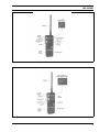
return to the normal system/group display.
Wide Area Scan (Optional)
When the radio unit loses the control channel of the
current system, the radio automatically begins searching for
a new control channel. The intelligent search algorithm uses
a preprogrammed map of adjacent systems to ensure minimum transition time.
Conventional - Pressing SHIFT/CLR
button twice ("double click") will enable MONITORING the channel for
activity by unsquelching the receiver.
All transmissions will be heard, even
if Channel Guard protected.
Dynamic Regrouping (Optional)
S
The Select buttons are two momentary (auto ramping) switches used to
increment or decrement the current
Group/Channel selection. Pressing
the shift button and then the S buttons
will increment or decrement the System selection. The Select buttons are
also used to increment or decrement
the Special Call selection while in the
Special Call mode.
V
The Volume buttons are two momentary (auto ramping switches) used to
increment or decrement the volume
level from the speaker. A tone sounds
each time the Volume buttons are
pressed, except when a call is in process.
HOME/E
The ON/OFF SWITCH is located on
the battery pack. Sliding this switch
up to the ON position will supply
power to the radio from the battery
pack. The radio will beep once after
power is applied indicating it is ready
for use.
The HOME/Emergency key is used
to automatically select a desired
Group and/or System by pressing and
holding the key for a programmed duration. The HOME/Emergency key
is also used to declare emergencies by
pressing and holding the key for a
preprogrammed duration. Emergency
messages may only be issued on
EDACS systems.
SPC
Pressing the PTT Button on the side
of the radio will key the radio’s transmitter and perform the necessary steps
to acquire a communication channel.
Pressing the SPC call key will put the
radio in the Special Call Mode. From
the Special Call Mode the radio is able
to make individual and interconnect
calls. This key is active with trunked
systems only.
SCAN-A/D
All alternate key functions are accessed by pressing the SHIFT/CLR
button and then pressing the desired
function key.
The SCAN-Add/Delete key is used to
enable the Scan mode and to add or
delete Groups/Channel to the Scan
list.
STO
The STOre key in combination with
the SHIFT/CLR button is used to
store Individual Call numbers and Interconnect numbers. This is available
on System Model radios and is active
with trunked systems only.
The unit is capable of being reprogrammed over the air
while the radio is still active. Multiple talk groups can be
added to a radio unit or optionally, the radio can be forced to
communicate on designated talk groups.
GE-MARC (Only) FEATURES
Talk Around (Direct Mode)
The radio is capable of a direct unit-to-unit short range
communication link. It is intended to maintain communications outside the coverage area.
OPERATION
The following section provides a description of the
Controls and Indicators for the Dual Format PCS radio.
Detailed operating instructions can be found in the Operator’s Manual LBI-38823.
CONTROLS
ON/OFF
SWITCH
PTT BUTTON
(Push-To-Talk)
SHIFT/CLR
Trunked - Pressing the SHIFT/CLR
button twice ("double click") will invoke the CLEAR function which is
used to exit the Special Call mode and
11
LBI-38836B
LOCK
The LOCK key in combination with
the SHIFT/CLR key is used to lock
the keypad. All buttons and keys will
be locked except the VOLUME, PTT,
H OM E/ E , SHIFT / CLR and the
LOCK (shifted 0). This key is available on System models only.
RCL
The RECALL key (shifted #) can be
used to recall manually entered individual and interconnect calls in the
EDACS and GE-MARC systems.
This is available on System model radios and is active with trunked systems only.
GRP icon is suppressed while operating from a Conventional System, but
the field is still used to display the
Channel selected.
Status Indicators
TX
The Transmitter flag is on when the
radio is transmitting.
BSY
The Channel Busy flag is on when the
radio receives a call or when a conventional channel is in use. The flag is
also on when transmitting on a
trunked channel. This flag flashes
when a call is qued on a trunked system.
BT
The Battery flag is on when the battery power is low and needs charging.
NO
EDACS - The NO Service flag is used
in conjunction with the Service flag to
indicate no service. The illumination
of both the NO and the SV flag indicates a no service condition.
INDICATORS
GE-MARC - The NO flag is used in
conjunction with the Service flag to
indicate an unsuccessful attempt to access a GE-MARC System. The illumination of both the NO and the SV flag
indicates a failed attempt to access a
GE-MARC system.
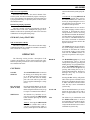
Figure 3 - Dual Format PCS Display
The 4-digit LIQUID CRYSTAL DISPLAY (LCD) uses
the two digits on the left side to indicate the System number
and the two digits on the right side to indicate the
Group/Channel number. In addition there are 9 status indicators.
LCD backlighting can be programmed to turn on anytime a button or key is pressed. It will remain on for a
programmable length of time after the button or key is
released. Backlighting is programmed on a per Group/Channel basis or it may be programmed to remain off at all times.
Each radio that is programmed with backlighting may also
be programmed to remain on or off when the PTT bar is
pressed.
CONVENTIONAL - The NO flag remains off at all times while operating
in Conventional mode.
SV
GE-MARC - The Service flag is normally off. If an unsuccessful attempt
is made to access a GE-MARC System, both the "SV" and the "NO" flags
will turn on.
System And Group/Channel Indicators
The SYStem display indicates the
number of the current EDACS, GEMARC or Conventional system selected.
CONVENTIONAL - The Service flag
remains off at all times while operating in Conventional mode.
SCN
The GRP (Group) display indicates
the number of the current Group in an
EDACS or GE-MARC System. The
12
EDACS - The Service flag is normally
on to indicate service. If a no service
condition occurs the "SV" flag and the
"No" Service flag will be illuminated.
The SCAN flag is on when Scan is
activated.
LBI-38836B
S
The "S" Flag is used to indicate two
conditions. The "S" flag is used in
conjunction with the "PC" flag to indicate the radio is in the Special Call
mode. The "S" flag is also used to
indicate when a trunked group is scan
enabled.
PC
The "PC" flag is illuminated with the
"S" flag to indicate the radio is in the
Special Call mode. When the "PC"
flag is illuminated without the "S"
flag, the radio is in the Program mode.
1
The "1" flag is used only for radio
logical ID display. When receiving an
individual call, the most significant
digit (0 or 1) of the originating radio’s
ID will be displayed by the (1) flag.
When on, the ID of the originating
radio begins with a 1.
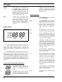
3.
Align the grooves on the top of the battery pack with the
grooves on the bottom of the radio.
4.
Slide the battery pack fully into the radio until the
battery release latch clicks into place.
BATTERY PACKS
Figure 4 - Installing The Battery Pack
The following battery pack are available for use with the PCS
Dual Mode radio:
PCPA1J
Rechargeable Battery Pack, High Capacity
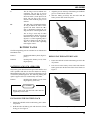
REMOVING THE BATTERY PACK
PCPA1K
Rechargeable Battery Pack, Extra
High Capacity
1.
Ensure the ON/OFF switch on the battery pack is in the
off position.
2.
Press down on the battery release latch and slide the
battery pack out in the direction of the release latch. See
Figure 5.
BATTERY PACKS (FM APPROVED)
Only battery packs identified with a green latch shall be used
with a portable radio that is rated and labeled as Factory
Mutual Intrinsically Safe. Use of nonspecified battery packs
voids Factory Mutual approval. The following battery pack
option is approved for use in intrinsically safe radios.
PCPA1L
Rechargeable Battery Pack, Extra
High Capacity, (Tall Case)
CAUTION
Battery packs used with the PCS radio must be
supplied by Ericsson GE.
INSTALLING THE BATTERY PACK
1.
Ensure the ON/OFF switch on the battery pack is in the
off position.
2.
Hold the radio and battery pack with the back of them
facing you. See Figure 4.
Figure 5 - Removing The Battery Pack
13
LBI-38836B
CHARGING THE BATTERY PACKS
locations in the presence of Groups A, B, C and D atmospheres.
New batteries or batteries that have been stored for a
long period of time, should be fully charged before placing
into service. When the battery pack requires charging the
"BAT" indicator in the LCD will turn on and the radio will
sound a high pitch tone every 130 seconds.
Hazardous locations are definedin the National Electrical Code. Useful standards NFPA 437A and NFPA 437M for
the classifications of hazardous areas can be ordered from
the National Fire Protection Association, Batterymarch Park,
Quincy, MA 02269.
Rechargeable batteries in some applications can develop
a condition of reduced capacity, sometimes called "Memory
Effect". This condition may occur when:
CHANNEL GUARD ENCODE/DECODE
1.
The battery is continuously overcharged for long periods of time.
2.
A regularly performed duty cycle allows the battery to
expend only a limited portion of its capacity.
If the rechargeable battery is only sparingly or seldom
used and is left on continuous charge for one or two months
at a time, it could experience reduced capacity. This would
severely reduce the life of the battery between charges.
The most common method of producing this limited
capacity is regularly performing short duty cycles; when the
battery is operated so that only a portion (2%) of its capacity
is expended. This type of operation can cause the battery to
become temporarily inactive and show severe decrease in the
ability to deliver at full rated capacity.
Any rechargeable battery showing signs of reduced capacity, should be taken to a qualified Service Technician to
be carefully checked before being returned under warranty
or scrapped.
Rechargeable Battery Pack Disposal
The product you have purchased contains
a rechargeable battery. The battery is recyclable. At the end of it’s useful life
under various state and local laws it may
be illegal to dispose of this battery into
the municipal waste stream. Check with
your local solid waste officials for details
concerning recycling options or proper disposal in your area.
Call Toll Free 1-800-8-BATTERY for information and/or
procedures for returning rechargeable batteries in your state.
Intrinsically Safe Usage
Selected portable radios with appropriate factory installed
F4 Options are certified as Intrinsically Safe by the Factory
Mutual Research Corporation. Intrinsically Safe approval
includes Class l, II, Ill, Division 1 hazardous locations in the
presence of Groups C, D, E, F and G atmospheres. Non-Incendive approval includes Class I, Division 2 hazardous
14
The radio can be programmed for Channel Guard
(CTTCSS) encode/decode tone frequencies of Hz to 210.7
Hz, including all of the standard EIA frequencies. Each
channel may be programmed for encode/decode, encode
only, decode only or for no Channel Guard frequency.
A list of the standard tone frequencies is shown in Table
1. A list of digital Channel Guard codes and their equivalents
are shown in Table 2.
Table 1 - CG Tone Frequencies
Standard Tone Frequencies Hz
67.0
97.4
136.5
192.8
71.9
100.0
141.3
203.5
74.4
103.5
146.2
210.7
77.0
107.2
151.4
79.7
110.9
156.7
82.5
114.8
162.2
85.4
118.8
167.9
88.5
123.0
173.8
91.5
127.3
179.9
94.8
131.8
186.2
1. Do not use 179.9 Hz or 118.8 Hz in areas served by
60 Hz power distribution systems ( or 100.0 Hz or
151.4 Hz in areas supplied with 50 Hz power). Hum
modulation of co-channel stations may “false”
Channel Guard decoders.
2. Do not use adjacent Channel Guard tone frequencies
in systems employing multiple Channel Guard
tones. Avoid same-areas co-channel use of adjacent
Channel Guard tones whenever possible. As stated
in EIA Standard RS-220, there is a possibility of
decoder falsing.
3. To minimize receiver turn-on time delay, especially
in system using Channel Guard repeaters or receiver
voting, choose the highest usable Channel Guard
tone frequency. Do not use tones below 100 Hz
when it is necessary to meet the receiver response
time requirements of EIA Standard RS-220.
LBI-38836B
EDACS SYSTEM DESCRIPTION
The Dual Format PCS 800 MHz digital trunked portable
radio provides fast access to available RF channels and a
degree of privacy due to selective signaling. This also eliminates annoyance of other system user’s conversations while
ensuring that intended calls are not missed.
The system uses 9600 baud high speed digital signaling
to identify individual units, user groups, fleets and agencies.
Agencies contain multiple fleets and fleets contain multiple
user groups simultaneously all the way down to individual
users can be accessed. This programming to determine transmit encoded groups and decoded received groups is contained in the personality EEPROM contained in the portable.
This information is individually programmed to each users
needs via the PC programmer for the radio.
Typical system configuration consists of at least 2 repeater stations (with a maximum number of 25), and the
associated portables. One repeater always is a control channel which is dedicated to sending out continuous control data
and also to receiving channel request data from the portables.
When a portable is first turned on it scans the available list
of frequencies programmed in the personality EEPROM for
a control channel. When a control channel is found the
portable locks onto the frequency and monitors the data for
channel assignment (incoming call).
When receiving a channel assignment (incoming call),
the monitoring portable immediately switches over to the
assigned voice channel and waits for a high speed data
confirmation message. Upon receipt of this message the
voice paths are unmuted and the user can hear the call.
While on the voice channel, the portable also continuously monitors the low speed, 150 baud (subaudible) data
and carrier noise squelch to ensure consistent operation.
Upon loss of subaudible data reception (i.e. deep fade, out
of range), the portable will return to the control channel
frequency.
To initiate a call, the user keys the radio (which is locked
to the control channel), and a 30 millisecond high speed data
slotted channel request is transmitted to the control channel
receiver. The control channel processes the request from the
portable and transmits back a voice channel assignment on
an unused channel.
When all available voice channels are in use, the control
channel will place the portable into a queue, transmit back
to the portable a queue message, and will give a channel
assignment to the requesting portable as soon as a voice
channel is free. If the system is busy and the station queue is
filled to capacity, a system busy message will be sent back
to the requesting portable and an alert will be given to the
user.
After the initiating portable receives a channel assignment from the control station, it immediately switches frequency over to the assigned voice channel and sends a burst
of 9600 baud dotting. The microphone voice paths are then
unmuted and the transmission begins. The transmitting portable also continuously sends out a subaudible tone (along
with voice) for system reliability. If the station looses this
signaling, the voice channel is muted and all receiving portables are sent back to the control channel.
In normal operation, the transmitting portable also sends
a phase shift on this subaudible tone to indicate that the user
has unkeyed, and to switch listening portables back to the
control channel.
GE-MARC SYSTEM DESCRIPTION
The GE MARC V•E digital trunked radio system also
provides fast access to available RF channels and a degree
of privacy due to selective signaling. It also eliminates annoyance of other system user’s conversations while ensuring
that intended calls are not missed.
Each system has a repeater for each channel (with a 20
channel maximum) and participating portables. The
Area/Group switch can address up to 10 systems, 10 combinations of systems and Groups within systems, or even 10
Groups within a single system. An Individual Call would
have a dedicated programmed Group encode address.
The system uses tone signaling, with each portable
being assigned 2 and/or 4 tone sequences to identify individual units or user groups that can be accessed. Groups of
portables are assigned the same tones, so that any unit can
talk to all other units in the same group. Programming to
determine transmit encoded groups and received decoded
groups is contained in the non-volatile Personality EEPROM
within the radio, as individually programmed for each user’s
needs with the PC programmer.
In a GE MARC V trunked system with a Dual Format
PCS System radio, a radio can be programmed to be able to
make a Special Call (a telephone interconnect) as an alternative to a programmed dispatch group call for each Area
address. Thus for each Area address with its list of channel
frequencies, two tone sets can be encoded for transmission,
a Group tone set and a Special Call tone set.
For the Direct Mode ’Talk- Around’ feature a command
from the radio’s logic circuitry will cause the Voltage Controlled Oscillator (VCO) to switch from the trunking transmit band to the 851-870 MHz band. This allows direct
transmission to another portable without going through a
system repeater.
15
LBI-38836B
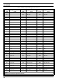
Table 2 - Primary & Equivalent Digital Codes (OCTAL)
PRIMARY
CODE
023
EQUIVALENT
CODE
340,766
025
PRIMARY
CODE
PRIMARY
CODE
EQUIVALENT
CODE
251
236, 704, 742
632
123, 657
261
227, 567
565
307, 362
026
566
263
213, 736
654
163, 460, 607
031
374, 643
265
171, 426
662
363, 436, 443, 444
271
427, 510, 762
664
344, 471, 715
032
043
355
306
147, 303, 761
703
150, 256
047
375, 707
311
330, 456, 561
712
136, 502
051
520, 771
315
321, 673
723
235, 611, 671
054
405, 675
331
372, 507
731
447, 473, 474, 744
065
301
343
324, 570
732
164, 207
071
603, 717, 746
346
616, 635, 724
734
066
072
470, 701
351
353, 435
743
312, 515, 663
073
640
364
130, 641
754
076, 203
074
360, 721
365
107
036
137
114
327, 615
371
217, 453, 350
053
115
534, 674
411
117, 756
122
535
116
060, 737
412
127, 441, 711
145
525
125
173
413
133, 620
212
253
131
572, 702
423
234, 563, 621, 713
225
536
132
605, 634, 714
431
262, 316, 730
246
542, 653
134
273
432
276, 326
252
661
143
333
445
222, 457, 575
255
425
152
366, 415
464
237, 642, 772
266
655
155
233, 660
465
056, 656
274
652
156
517, 741
466
144, 666
325
550, 626
162
416, 553
503
157, 322
332
433, 552
165
354
506
224, 313, 574
356
521
172
057
516
067, 720
446
467, 511, 672
174
142, 270
532
161, 345
452
524, 765
205
135, 610
546
317, 614, 751
454
513, 545, 564
223
350, 475, 750
606
153, 630
455
533, 551
226
104, 557
612
254, 314, 706
462
472, 623, 725
243
267, 342
624
075, 501
523
647, 726
244
176, 417
627
037, 560
526
562, 645
245
370, 554
631
231, 504, 636, 745
NOTE:
Primary codes in bold are unique Ericsson codes.
16
EQUIVALENT
CODE
LBI-38836B
ORIGINATING A CALL
When originating a call, the portable identifies an idle
repeater channel and interrogates it with a single burst of
"busy" tone, the repeater keys its transmitter and sends a
burst of "acquisition" tone back to the portable unit. When
the interrogating portable detects the acquisition tone, it then
transmits its collect and group tones, which the repeater
regenerates for all idle portable units in the system.
The idle portables, which continually scan all channels,
will stop on the active channel if any of the programmed
collect tones are detected and wait for group tone(s).
If the correct tone sequence is detected, the portables
will alert the operator to an incoming call and open their
audio circuits. If the correct sequence is not detected, the idle
portables will resume scanning the channels. Once the portable is "locked" on a channel, it will remain there until the
repeater times out or the operator terminates the call.
The radio enters the idle mode when power is turned on
and begins scanning channels for incoming calls. The wait
mode is entered when the user places a call. The radio
remains in the wait mode until a channel is acquired, or if no
channel is available. The ready or conversion mode is indicated by an alert tone. A tone signalling Timing Diagram is
shown in Figure 7. Sequence Flow Charts for each operational mode are shown in Figures 8, 9 and 10.
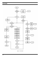
Idle Mode (Figure 8)
When the radio is in the Idle Mode, the audio is muted
and all channels programmed for call decode are sequentially
scanned for an incoming call. An incoming call is identified
by detecting one of the collect tones programmed in the area.
Upon receipt of a collect tone, the portable looks for a short
interval for the group or individual tones, providing that their
collect tones are the same. When no valid tone is found, the
portable will resume scanning the channels for an incoming
call.
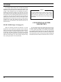
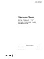
OPERATIONAL MODES
The radio will always be in one of three operational
modes; idle, wait, or ready. The three operational modes and
the conditions that cause the radio to switch from one mode
to another are shown in Figure 6.
If a group (or individual decode) tone is detected the
portable then looks for busy tone for a 90 millisecond period.
If four tones are properly decoded, the portable willthen look
for busy tone for 270 milliseconds.
When no valid tones are found, the portable will resume
scanning for a call with the next channel. When a busy tone
is found, the portable will enter the Ready Mode. If busy tone
is not detected, the portable remains in the Idle Mode and
continues scanning channels looking for an incoming call.
Pressing the PTT switch will cause the radio to enter the Wait
Mode.
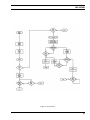
Wait Mode (Figure 9 on page 20)
When the user enters the Wait mode, the group tone is
checked to make sure it is a valid call-originate group. It if
it not valid, a high-frequency steady tone is heard in
GE_MARC V•E systems only. If valid, the radio will scan
the call-originate frequencies for brief intervals until it finds
one with no busy tone on it. If no channel is free, the radio
will activate the Call Retry state if programmed for this
option. This causes the radio to revert to the Idle mode and
scan for a call while trying the Wait mode approximately
every 20 seconds for a five minute period. If the Retry option
is not programmed the portable will sound a low-frequency
tone, and then return to the idle mode.
Figure 6 - Operational Modes
17
LBI-38836B
If a channel with no busy tone is found, the portable
transmits a burst of busy tone to acquire the repeater. The
repeater then responds with a burst of acquisition tone. Upon
receipt of the acquisition tone, the portable proceeds to
transmit the group tones (either two or four tones). If a four
tone sequence is sent, the portable must detect all four tones
and busy tone before entering the Ready Mode. If a two tone
sequence is sent, the busy tone must be present within 90
milliseconds of the last tone in order for the radio to enter
the Ready mode. If no busy tone is present, or if the four tone
sequence isn’t valid, the portable will jump to the next
channel in the call originate set and check for busy tone as
described above.
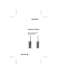
READY MODE (Figure 10 on page 21)
When an incoming call has been detected, or an idle
channel has been acquired, the portable enters the Ready
mode. In this mode, the audio and push-to-talk circuits are
enabled, the speaker is unmuted, and the operator is alerted
an alert tone. The radio can then be used in the conventional
push-to-talk manner with the radio remaining on the channel
until the operator hangs up or the repeater drops the busy
tone, causing the unit to revert to Idle mode.
18
NOTE
If a call is initiated and a sequence of five beeps is
sounded, the user cannot access the radio system
due to being out of portable receive range or being
inoperative. Any subsequent call will be ignored for
20 seconds.
CONVENTIONAL SYSTEM
DESCRIPTION
In conventional mode (not trunked) the radio can operate either with tone Channel Guard, digital Channel Guard,
or carrier squelch; depending on personality programming.
Tone Channel Guard range is 67.0 to 210.7 Hz. Squelch Tail
Elimination (STE) is used with tone Channel Guard to eliminate squelch tails at the receiving radio by phase shifting the
transmitted Channel Guard tone when the PTT is released.
LBI-38836B
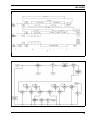
Figure 7 - Tone Signal Timing
Figure 8 - Idle Mode
19
LBI-38836B
Figure 9 - Wait Mode
20
LBI-38836B
Figure 10 - Ready Mode
21
LBI-38836B
Ericsson Inc.
Private Radio Systems
Mountain View Road
Lynchburg, Virginia 24502
1-800-528-7711 (Outside USA, 804-528-7711)
Printed in U.S.A.