1
MANUAL
STR45-1
STR45-3
STR60-1
STR60-3
STR75-1
STR75-3
STR90-1
STR90-3
STR120-3
STR150-3
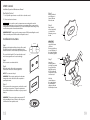
Congratulations on your purchase of SAWO Steam Generator.
Please read the manual carefully before using the steam generator.
KATSO
TÄRKEÄOHJEISTA
T LISÄO
HJEET
LÄGG
VIKTIG MÄRKE TIL
L DE
TILLÄGA
GSAN
VISNIN
BEACH
GARN
A
ZUSÄTZTEN SIE DIE
WICHTI LICHEN
GE
N
ANWE
ISUNG
BEDIEN
UNGSEN IN DER
ANLEI
READ
TUNG
ADDIT THE MANU
IONAL
AL
INSTRU
IMPOR FOR
CTION
TANT
S
STR
230V
kW 1N
~
!
RESIDENTIAL
STEAMBATH
GENERATOR
SYSTEMS
WARNING
1. Children under the age of 16 should not use the Steambath.
2. Check with a physician before use of the Steambath if you are pregnant, have a coronary condition, are in
poor health, are being treated for any other medical condition, or are using medication or drugs.
3. Exit Steam Room immediately if you feel faint, dizzy, sleepy, or otherwise uncomfortable.
4. Do not use the Steambath if you have recently consumed alcohol.
5. Condensation and moisture may cause the the Steambath floor and other surfaces to become slippery and
dangerous. Installation of non-skid floor materials or the use of proper footwear is recommended at all times.
IMPORTANT! Read the manual provided for use and safety information.
SAWO
SAWO, Inc. SAWO Building Mactan Export Processing Zone 2 Cebu, Philippines 6015
www.sawo.com
Residential Steambath Generator Systems
Before Installing
Installation, Operation & Maintenance Manual
•
MODELS:
TABLE OF CONTENTS
STR75-3
Before Installing.............................................................................. 3
STR45-3
STR90-1
Locating the Steam Generator.................................................... 4
STR60-1
STR90-3
•
Installation....................................................................................... 5
STR60-3
STR120-3
•
STR75-1
STR150-3
Generator Diagram....................................................................... 6
IMPORTANT: SAWO units are intended to be operated with SAWO Controls only, and are to
be installed strictly in accordance with the specific instructions contained in this manual and
as supplied in the manuals provided with the controls.
Electrical............................................................................................ 7
Field Power Wiring.......................................................................... 8
Wiring Diagrams............................................................................ 9
Optional Tandem Cable................................................................ 10
for connecting 2-5 steam generators in tandem
KATSO
TÄRKE OHJEISTA
ÄT LISÄO
HJEET
LÄGG
VIKTIG MÄRKE TILL
DE
TILLÄGA
GSANV
ISNING
BEACH
ARNA
ZUSÄT TEN SIE
WICHTZLICHENDIE
ANWE IGEN
BEDIEISUNGEN
IN
NUNG
SANLEDER
READ
ITUNG
ADDIT THE MANU
AL FOR
INSTRIONAL IMPOR
UCTIO
TANT
NS
STR
230V
kW 1N~
1. Steam room must be completely enclosed, with full walls, door, floor and ceiling.
2. It is recommended that a gasketed door is used for heat sealing and steam containment.
3. If tile-type or other smooth surfaced flooring is used provide suitable anti-skid strips or
equivalent, to prevent user slipping and injury.
4. Walls and ceilings must be constructed of water-resistant, non-corrosive surface, such as tile,
marble, molded acrylic, or other non-porous material.The ceiling should be sloped to prevent
dripping of condensate. If acrylic, fiberglass or other non-heat resistant materials are used as
part of the steamroom enclosure.
5. Provide a floor drain.
6. No heating, venting or air conditioning devices should be installed inside the steam room.
7. Windows that are part of the steamroom should be double paned.
8. Try to limit steamroom ceiling height to 2.5m. Exceeding 2.5m may require a higher-rated
steam generator.
9. SAWO strongly recommends that a warning be posted in a conspicuous location near the
steambath.
Select Your SAWO Model...............................................................13
STR45-1,STR45-3,STR60-1,STR60-3,STR75-1,STR75-3
STR90-1 and STR90-3 (with Automatic drain)................................... 14
STR120-3 and STR150-3 (with Automatic drain).............................. 15
Installing the Remote Temperature Probe................................ 16
SAWO Control..................................................................................18
IMPORTANT NOTE: As you follow these instructions, you will notice warning and caution symbols. This
blocked information is important for the safe and efficient installation and operation of this generator.
These are types of potential hazards that may occur during this installation and operation:
WARNING !
states a hazard may
cause serious injury
or death if precautions
are not followed.
CAUTION !
signals a situation where
minor injury or product
damage may occur if you
do not follow instructions.
WARNING ! Electrical shock hazard. SAWO steam generators are connected to 220-240V
(One Phase models only: STR45-1,STR60-1, STR75-1 and STR90-1), or 380-430V (Three Phase
models only: STR45-3, STR60-3, STR75-3, STR90-3, STR120-3 and STR150-3) line voltage and
contain live electrical components. All installation and service to be performed by qualified
and licensed electricians and plumbers only. Installation or service by unqualified persons may
void the warranty.
Steam Room Guidelines
Optional Automatic Drain System............................................. 12
2
•
•
STR45-1
IMPORTANT: The following general information should be used in conjunction with
consultations with your architect, designer and contractor in determining all factors necessary
in providing a suitable and safe steam room.
Read these instructions before installation or service. Although this steambath generator
has been fully qualified for shipment by SAWO, the following must be reviewed for proper,
safe and enjoyable steam bathing.
Verify that the model and accessories are correct, including incoming line voltage.
Insure steambath generator has been correctly sized for the steambath room. Pay particular
attention to room volume and construction. If any questions, please refer to SAWO sizing
guide enclosed (see page 13).
Marble or glass walls or ceilings, or exterior walls "ENLARGE" the room's size, requiring a
generator larger than one based only on the room's (L x H x W) volume.
The physical size of the unit, clearance for plumbing servicing, and its distance from the steam
room must all be considered before final installation.
IMPORTANT NOTE:
This highlights information
that is especially relevant
to a problem-free
installation.
!
WARNING
1. Children under the age of 16 should not use the Steambath.
2. Check with a physician before use of the Steambath if you are pregnant, have a coronary condition, are in
poor health, are being treated for any other medical condition, or are using medication or drugs.
3. Exit Steam Room immediately if you feel faint, dizzy, sleepy, or otherwise uncomfortable.
4. Do not use the Steambath if you have recently consumed alcohol.
5. Condensation and moisture may cause the the Steambath floor and other surfaces to become slippery and
dangerous. Installation of non-skid floor materials or the use of proper footwear is recommended at all times.
IMPORTANT! Read the manual provided for use and safety information.
SAWO
SAWO, Inc. SAWO Building Mactan Export Processing Zone 2 Cebu, Philippines 6015
WARNING
!
www.sawo.com
The STR series of steam generators are for residential use only.
Commercial or other non residential applications void the
warranty and may adversely affect product performance.
3
Locating the Steam Generator
Installation
Select a location as near as practical to the steam room.Typical locations include:
closet, vanity cabinet, heated attic or basement.
1. Locate steambath generator within 7.5 meters of steam room.
NOTE: The standard length of the cable for connecting the control to the steam generator is
7.5 meters.The steam generator and control must be located accordingly.
2. Do not install steambath generator inside steam room.
3. Do not install steambath generator outdoors or wherever environmental conditions may
affect the safety and/or performance of the generator.
4. Do not install steambath generator or plumbing lines in unheated attic or any locations
where water could freeze.
5. Do not install steambath generator near flammable or corrosive materials or chemicals such
as gasoline, paint thinners, or the like. Installation in areas having high concentrations of
chlorine (such as pool equipment room) must be avoided.
6. Install steambath generator on a solid and level surface. Keyhole slots are provided on for wall
mounting. Insure the steam generator is properly secured and level when mounting with
keyhole slots.
7. Install steambath generator in an upright position only.
8. Install anti-water hammer device as necessary.
9. Provide a minimum of 30 cm at both ends and top of the steam generator or as required for
servicing.
10. Provide unions as required to facilitate installation and disconnection of piping.
11. IMPORTANT: Steam line, safety valve, drain valve, plumbing and steamheads become hot
during operation and remain hot after shutdown for a period of time. Provide appropriate
protection, including insulating plumbing lines. Avoid plumbing runs and steamhead
locations that can come in contact with bathers.
12. SAWO controls can be located inside the steam room or on the outside of the steam room.
NOTE: SAWO Generators are CE compliant.
WARNING
All plumbing shall be performed by a qualified licensed plumber and in accordance with
applicable National and local codes.
• Use unions on all pipe connections.
• Use only brass piping or copper tubing as permitted by codes.
• Do not use black, galvanized or PVC pipe.
Water Supply (10mm)
1. Connect hot or cold water line. Hot water line is preferable, however hot water should not
exceed 70ºC.
2. Provide a shut off valve in the water supply line upstream of the steambath generator.
3. Do not overheat inlet solenoid valve with solder connections. Overheating will damage parts.
4. Flush inlet water line thoroughly before making connection to unit.
5. Strainer recommended upstream of feed water connection.
6. For best performance water pressure should be 1 to 1.4 bar. Reduce pressure as required
if necessary.
7. Provide anti-water hammer device as required.
Steam Outlet (15mm)
1.
2.
3.
4.
Do not install any valve in steam line. Flow of steam must be unobstructed.
Use 15mm brass pipe or copper tubing from unit to steam head as permitted by codes.
Insulate steam line using pipe insulation rated 120ºC or higher.
Pitch steam line 2cm per meter towards steam head or steam generator to avoid valleys and
trapping of condensate.
NOTE: Running the steam line down and then up will create a steam trap blocking the
flow of steam.
Steam Head (15mm)
The SAWO steam generators are for residential use only. Commercial or other
non-residential applications void the warranty and may adversely affect product
performance. Use only SAWO controls.
!
NOTE: For illustrative purposes only.
Consult with qualified designer, architect or
contractor for steam room construction details.
SAWO in-shower control
Control cable
Field installed
power supply
Plumbing
Field
installed
water
supply
pipe
Temperature sensor
CAUTION ! INSTALLER Because the steam head and direct steam emissions are very hot,
locate the steam head where incidental contact by bather with the steam head or direct
steam emission cannot occur.
1. Locate steam head 15-30cm above floor, except for
6mm minimum
clearance required
• Tub/shower enclosures, install 15cm above tub top edge.
when Acrylic Shield
• For enclosures with acrylic or other non-heat resistant Use Teflon or
(PN 103412) is used.
See installation
equal sealant
flooring install Acrylic Shield.
instructions provided
on pipe threads.
2. Install steamhead with steam head facing downward.
with the Acrylic Shield.
Hand tightening is sufficient when teflon or equal pipe
thread sealing compound is used.
IMPORTANT: To preserve steam head finish, do not
Steam Supply Pipe
Steam Head
use wrench or other tools to tighten. Use no abrasive
cleansers or chemicals. Use only water with mild soap
and a non-abrasive sponge.
13mm
(w/o Acrylic Shield)
Fill gap with
3. IMPORTANT: Consult with supplier of acrylic,
silicone or equal
19mm
fiberglass and other non-heat resistant enclosures
sealant as required
(with Acrylic Shield)
for moisture seal.
for recommended steamhead location.
Finished interior face
Use an Acrylic Shield.
of steam room wall
Drain (15mm)
Steam generator
NOTE: A drain valve is provided to facilitate servicing. Provide a drain line connection from
steambath generator drain valve according to National and local requirements. Check local
plumbing code for receptor, trap and vent requirements. Unit drains by gravity.
Field installed
steam supply
pipe
Valve is
Provide unions as required to facilitate
shown open
installation and disconnect of piping
Steam Head (shown with optional acrylic shield)
Safety Valve (20mm)
Where permitted by local codes, provide an outlet plumbing connection for safety valve.
4
WARNING
!
To insure proper and automatic safety valve operation: DO NOT connect
a shut off valve or a plug at safety valve outlet. DO NOT connect a shut off
valve in steam supply pipe.
5
Electrical
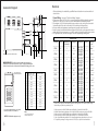
Generator Diagram
All electrical wiring to be installed by a qualified licensed electrician in accordance with local
electrical code.
/---------------------------------\
Safety
Valve
Optional
Automatic Drain
A
/-----------\
Manual Drain
Valve
J
30cm
/---
/------------------------------------------------------------
/----- L ----\
Minimum clearance for element service
C
/----- F ----\
K -----------------------------------------------------------\
---\
B
/------------------------------------------------------------------------------\
Steam
Outlet
/-----------------------------------------------------\
Water Inlet
/----------- G ---------\
/-------------------------- M -----------------------\
/------------------ H ---------------- \
/-------------------------------------
I ------------------------------------
\
IMPORTANT NOTE: Provide clearance around steam generator as
required for service and maintenance. DO NOT rough in plumbing and
electrical services based on dimensional information. Drawing not to scale.
Side view showing
element access panel
STR45-1, STR45-3, STR60-1,
STR60-3, STR75-1, STR75-3,
STR120-3 and STR150-3
STR90-1 and STR90-3
__________________________________________
A
140
184
__________________________________________
B
210
254
__________________________________________
C
302
310
__________________________________________
D
375
466
__________________________________________
E
45
152
__________________________________________
F
48
64
__________________________________________
G
89
102
__________________________________________
H
127
152
__________________________________________
I
171
200
__________________________________________
J
45
35
__________________________________________
K
368
502
__________________________________________
L
64
60
__________________________________________
M
TO AVOID EQUIPMENT DAMAGE DO NOT CONNECT
POWER SUPPLY DIRECTLY TO ELEMENTS !!!
NOTE: For illustrative purposes only.
6
152
NOTES:
1. M = Optional Automatic drain
2. All units in millimeters (mm)
162
/--------------------------------------------------------------------------------------------------\
/---- E -----\
D
Power Wiring - See page 8 "Field Power Wiring" diagrams.
1. Check power voltage. Use 220-240V to connect a single phase SAWO residential steambath
generator. Use 380-430V to connect a 3 phase SAWO residential steambath generator.
2. Use minimum 90ºC / 600V rated insulated copper conductors only, sized in accordance with
National Electrical Code and local electrical code for the Amps in Ampere Chart.
3. Connect suitably sized equipment grounding wire to ground terminal provided.
4. Install a separate circuit breaker between supply and unit. Provide a power supply disconnect
within sight of the steam generator or one that is capable of being locked in the open position.
5. For single phase units, use two-wire supply source and equipment grounding wire.
AMPERE CHART
Model No.
kW
Maximum Room Voltage (V)
Current (A)
Phase
Wire Size
Volume
(m³)
mm²
_____________________________________________________________________
18A @ 220V
1
4mm²
240
STR45-1
4.5
2
19A @ 240V
_____________________________________________________________________
6A @ 380V
3
2.5mm²
STR45-3
4.5
2
415
7A @ 415V
7A @ 430V
_____________________________________________________________________
23A @ 220V
1
6.0mm²
STR60-1
6.0
5
240
25A @ 240V
_____________________________________________________________________
8A @ 380V
415
9A @ 415V
STR60-3
6.0
5
3
2.5mm²
9A @ 430V
_____________________________________________________________________
29A @ 220V
240
STR75-1
7.5
7
1
6.0mm²
32A @ 240V
____________________________________________________________________
10A @ 380V
3
2.5mm²
STR75-3
7.5
7
415
11A @ 415V
11A @ 430V
_____________________________________________________________________
35A @ 220V
STR90-1
9.0
11
240
1
8.0mm²
38A @ 240V
_____________________________________________________________________
12A @ 380V
3
2.5mm²
STR90-3
9.0
11
415
13A @ 415V
13A @ 430V
_____________________________________________________________________
16A @ 380V
415
17A @ 415V
STR120-3
12.0
16
3
4mm²
18A @ 430V
_____________________________________________________________________
20A @ 380V
415
3
4mm²
21A @ 415V
STR150-3
15.0
19
22A @ 430V
_____________________________________________________________________
Provide a power supply disconnect within sight of the steam generator or one that is capable of being
locked in the open position as permitted by code.
1. When operated on 220V/1PH, kW output will be 84% of rated kW at 240V/1PH.
2. All three phase heating elements used on 380-430V/3PH products are rated at 415V/3PH.
3. When operated on 380V/3PH, kW output will be 84% of rated kW at 415V/3PH.
4. When operated on 430V/3PH, kW output will be 107% of rated kW at 415V/3PH.
5. Only copper field wiring suitable for 90 degree Centigrade-rated insulation is to be used.
6. For product operating on voltages in excess of 250V, use only 600V rated insulation.
7
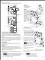
Field Power Wiring
Wiring Diagrams
All
L E G E N D Diagrams
Models STR45-1, STR-60-1, STR75-1 and STR90-1
Ground Lug
Ground
FIELD
WIRING
FACTORY
WIRING
POWER
INPUT
L
N
G
TRANSFORMER
BLACK
L
N
SINGLE PHASE
WHITE
DARK
BLUE
BLACK
STR45-1, STR60-1,
STR75-1, STR90-1
Contactor
L, N, Ground
by field wiring
GREEN
Knock-out
(fitting omitted
for clarity)
GROUND
TO
PR OB E
WHITE
C
LIGHT
BLUE
SAWO
CONTROL
CONTACTOR
_________________________________________________
TO AVOID EQUIPMENT DAMAGE DO NOT CONNECT
POWER SUPPLY DIRECTLY TO ELEMENTS !!!
_________________________________________________
NOTE: For illustrative purposes only. Consult with
qualified licensed electrician for electrical installation.
WHITE
S
GRAY
T E MP S E N S O R
WATER
FEED
SOLENOID
VALVE
HEATING
ELEMENT
CONTROL
BOARD
AUTOMATIC
DRAIN
S AWO 230 VOLT S S ING L E PHAS E WIR ING DIAG R AM
Models STR45-3, STR60-3, STR75-3, STR90-3, STR120-3 and STR-150-3
P OWE R INP UT
Ground Lug
L1
L2
L3
N
G
T R A N S F O R ME R
B LAC K
WHIT E
DAR K
BLUE
B LAC K
THREE PHASE
STR45-3, STR60-3,
STR75-3, STR90-3
STR120-3, STR150-3
GREEN
PUR PLE
Knock-out
(fitting omitted
for clarity)
GR OUND
TO
PR OB E
WHIT E
C
L1, L2, L3, N, Ground
by field wiring
L IG HT
BLUE
SAWO
CONTROL
CONTAC TOR
WHIT E
S
_________________________________________________
TO AVOID EQUIPMENT DAMAGE DO NOT CONNECT
POWER SUPPLY DIRECTLY TO ELEMENTS !!!
_________________________________________________
NOTE: For illustrative purposes only. Consult with
qualified licensed electrician for electrical installation.
8
G R AY
H E AT I N G
E L E ME N T
WA T E R
FE E D
S OL E NOID
VA LV E
C O NT R OL B OA R D
AUTOMATIC
DRAIN
S AWO 415 VOLT S T HR E E PHAS E WIR ING DIAG R AM
9
Optional Tandem Cable - for connecting 2-5 steam generators in tandem
3, 4 OR 5 SAWO UNITS
POWER INPUT
L
N
TRANSFORMER
BLACK
WHITE
FIELD
WIRING
MASTER UNIT
FACTORY
WIRING
DARK
BLUE
BLACK
Box Contents:
* Automatic drain Valve with Cord
* Installation instructions
(2) Pin Connector
for Automatic
drain
GREEN
FUSES
PURPLE
GROUND
ROUND
LIGHT
BLUE
SAWO
Control
CONTACTOR
ONTACTOR
S
WHITE
GRAY
Automatic Drain
WATER FEED
SOLENOID
VALVE
HEATING
ELEMENT
PLUG THIS END
TO MASTER UNIT
TO
PROBE
WHITE
CONTROL BOARD
OPTIONAL TANDEM CABLE
FOR 2-5 GENERATORS
Length is 9 meters
POWER INPUT
L
N
TRANSFORMER
BLACK
WHITE
SECOND UNIT
DARK
BLUE
BLACK
GREEN
FUSES
PURPLE
GROUND
TO
PROBE
WHITE
LIGHT
BLUE
Operation
The optional Automatic drain
feature automatically drains
the SAWO system following
each use. the stainless steel
tank is flushed and remains
empty until the steam
generator is used again.
A time delay (about 2
hours) allows the water to
cool down before it drains
resulting in a safe gentle
operation.
CONTACTOR
CO
S
HEATING
HEATING
ELEMENT
ELEMENT
Automatic drain Cord
KATSO
TÄRKE OHJEISTA
ÄT LISÄO
HJEET
LÄGG
VIKTIG MÄRKE TILL
DE
TILLÄGA
GSANV
ISNING
BEACH
ARNA
ZUSÄT TEN SIE DIE
WICHTZLICHEN
ANWE IGEN
BEDIEISUNGEN
IN
NUNG
SANLEDER
READ
ITUNG
ADDIT THE MANU
AL FOR
INSTRIONAL IMPOR
UCTIO
TANT
NS
Automatic drain Valve
STR
230V
kW 1N~
Arrow indicates
correct direction
of flow
Steam Generator
WHITE
GRAY
WATER FEED
SOLENOID
VALVE
Automatic drain Cord Connector
Automatic Drain
Drain Valve
CONTROL BOARD
(shown in the correct open position)
DO NOT REMOVE THIS DRAIN VALVE
TO THIRD UNIT
Installation Instructions
Nipple
(copper or
brass nipple
15mm x 90mm
or longer
(not supplied))
End
"B"
End
"A"
Plumb to Drain
Line in accordance
with Code
1. Disconnect all power supplied to the unit.
TO FOURTH UNIT
Initial Start-Up and Checkout
TO FIFTH UNIT
1. Turn on control. Follow specific instruction sheet provided with controls.
2. Steam will begin to appear in 5 minutes at the steam head. Steam will shut off when desired
temperature is reached and will automatically resume when room temperature drops below
set point.
3. Steam will shut off automaticaly when control counts down to zero. to shut steam off manually,
turn control OFF. To clear steam from enclosure area, turn shower on before opening door.
4. If unit does not start and control does not turn ON (control display does not light up) then turn
breaker off for twenty seconds and try again.
Optional Equipment
Refer to specific instruction sheets for installation, operation and maintenance of optional
equipment and accessories.
Maintenance
SAWO steambath generators require little maintenance. Other than periodic draining,
maintenance procedures are minimal. Every 2 months, or more often in "hard" water areas, the
manual drain valve should be opened fully flushing out accumulated materials, salts and other
particles which are naturally by-products of boiling water.
NOTE: Flush a minimum of two hours after the control has been turned off to insure that the
water has cooled.
10
WARNING ! Draining immediately after a steam cycle may expose PVC and other piping
to high temperature water. Check local requirements. The unit will refill automatically when
the control is activated again. In areas of very hard water, a SAWO automatic drain
system is recommended for generator longevity.
2. Plumbing to be performed by a qualified licensed
plumber and shall be in accordance with applicable
national and Local Codes. Unit drains by gravity.
A drain line that is lower than Automatic drain
assembly must be available. The Automatic drain
valve outlet is threaded 15mm. Check plumbing
code for receptor, trap and vent requirements.
3. Use copper or brass nipple 15mm x 90mm
or longer (not supplied) to connect the Automatic
drain valve (end "B") to the Drain Valve (valve end
"A" & "B" are indicated on bottom of Automatic
drain Valve).
Automatic
drain
Valve
KATSO
TÄRKE OHJEISTA
ÄT LISÄO
HJEET
LÄGG
VIKTIG MÄRKE TILL
DE
TILLÄGA
GSANV
ISNING
BEACH
ARNA
ZUSÄT TEN SIE DIE
WICHTZLICHEN
ANWE IGEN
BEDIEISUNGEN
IN
NUNG
SANLEDER
READ
ITUNG
ADDIT THE MANU
AL FOR
INSTRIONAL IMPOR
UCTIO
TANT
NS
STR
230V
kW 1N~
CAUTION
DO NOT REMOVE THE DRAIN VALVE.
Removal may cause equipment and property
damage. If there is not enough room for the valve,
an elbow and a short nipple (not provided) can
be added.
!
4. Open Drain Valve (handle must be aligned with
brass nipple as shown).
5. Connect the Automatic drain cord connector to the
two pin connector as shown.
Steam Generator
Drain Valve Nipple
DO NOT TURN OR REMOVE THE DRAIN VALVE
Plumb to
Drain Line
Automatic drain shown fully assembled
NOTE: For illustrative purposes only.
WARNING ! Do not drain into a steam enclosure or
any location where accidental contact with drain
water may occur. In the event of a power failure, the
Automatic drain valve will open and discharge hot water.
11
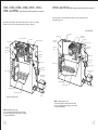
Select Your SAWO Model
Optional Automatic Drain System
Sweat Fittings
When using sweat fittings use only tin base solder with a melting point below 315ºC.
Do not overheat. Ends of water supply tubing must be thoroughly cleansed for a minimum
distance of 25mm from ends. Do not remove valve cover.
To Check Operation
1.
2.
3.
4.
5.
Turn on SAWO and allow tank to fill with water.
Turn off SAWO control. Water should stay in tank.
Turn off power at the panel box. Water should discharge from tank.
Turn on power at panel box.
Repeat.
PROVIDE DRAIN PLUMBING ACCORDING TO LOCAL REQUIREMENTS.
PLUMB AS REQUIRED FOR GRAVITY DRAIN SYSTEM.
1. Measure the Length, Width, and Height (in meters)
of steam shower or tub/shower being used.
L
W
H
Multiply the Length x Width x Height to get
the basic room volume in m3 (a) L x W x H =
a
2. Add 15% of (a) for each of the following design features
that describe the steambath enclosure:
b. Each exterior wall, or uninsulated attic, or crawlspace
.
above or below ceiling or floor
c. Tile on mud wall
d. An extra glass panel in addition to the door
e. A cast iron tub or marble bench
f. Each foot exceeding 2.5 meters height
3. If the interior wall construction material within the steam
enclosure is natural marble, stone, shale, glass block or
concrete, copy the figure from box (a) to box (g).
Using Aroma Oils
Enjoy aroma oils by placing a drop or
two into your steamhead as shown in
the attached illutration. Only use SAWO
aroma oils in a SAWO steamhead, or any
other equivalent oil deemed suitable for
use in the SAWO steamhead.
CAUTION ! Use aroma oils with caution.
aroma oils are for external use only. Keep
out of reach of children. aroma oils are highly
concentrated and are potent substances and
should not be applied directly to the skin as they
can be irritants. Use aroma oils with caution.
CAUTION
Aroma oil
10ml bottle with
integrated
dropper
Add Boxes (b) through (g) to box (a) = Total Cubic Meter
required.
a+b+c+d+f+g=
c
d
e
f
g
h
Compare the total m³ required (h) to the specification chart below and select the appropriate model.
_______________________________________________________________________________________________________
Recess for
essential oil
IMPORTANT: The formula for selecting the steambath generator is a recommendation only.
Because of variables in construction, these sizing instructions and specifications should be
considered as guidelines only. SAWO will review the model selected provided we receive complete
information, including working drawings, specifications, and pertinent electrical and construction
details. Otherwise the manufacturer disclaims responsibility for the sizing of a model selected.
Steam head
(install per instructions
on page 5)
Steam emission slot
Place the drops into the SAWO steamhead recess prior to turning on the
steambath. Do not place drops in a hot steamhead as SERIOUS INJURY CAN RESULT IF YOU
DO NOT FOLLOW THIS WARNING.
!
CAUTION ! Start with one drop to gauge strength and suitability. Limit to a maximum of a few
drops during a steambathing session. Some people may find that the aroma makes dizzy and
the user should exit the steam bath IMMEDIATELY. If skin irritation occurs stop using the oils
immediately. Remove any excess oil by washing in mild soap and water. If ingested, rinse
mouth with water. Administer water or milk to dilute. contact a physician immediately.
12
b
SELECTION CHART
Model No.
Kw
Maximum Room
Volume (m³)
_____________________________________________________________________
STR45-1
4.5
2
_____________________________________________________________________
STR45-3
4.5
2
_____________________________________________________________________
STR60-1
6.0
5
_____________________________________________________________________
STR60-3
6.0
5
_____________________________________________________________________
STR75-1
7.5
7
____________________________________________________________________
STR75-3
7.5
7
_____________________________________________________________________
STR90-1
9.0
11
_____________________________________________________________________
STR90-3
9.0
11
_____________________________________________________________________
STR120-3
12.0
16
_____________________________________________________________________
STR150-3
15.0
19
_____________________________________________________________________
13
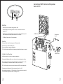
STR45-1, STR45-3, STR60-1, STR60-3, STR75-1, STR75-3,
STR90-1 and STR90-3 (with Automatic drain) shown with cover removed
STR120-3 and STR150-3 (with Automatic drain) shown with cover removed
STR120-3 and STR150-3 are supplied standard with a SAWO Control and a matching steam head.
The weight is 32 kg per unit.
Models STR45-1, STR45-3, STR60-1, STR60-3, STR75-1, STR75-3, STR90-1 and STR90-3 are compatible
with SAWO Controls and include a matching steam head. The weight is 21 kg per unit.
cover removed
Ground Lug
Power Block
Liquid Level Circuit Board
Power Block
Contactor
Transformer
Water Feed Solenoid
Power Supply
Knock-Out
Transformer
Power Supply
Knock-out
Water Feed Solenoid
Liquid Level
Probe
Liquid Level
Probe
Liquid Level
Control Board
Plug and Play
Connection
Water Feed
Plug and Play
Connection
Water Feed
Steam Outlet
Water Feed Hose
Safety Valve
Access Cover
Water Feed Hose
Steam Outlet
Safety Valve
Access Cover
Automatic Drain Valve
(optional)
Automatic drain
Valve (optional)
Heating Element
Stainless Steel Tank
Drain Line
Heating Element
Stainless Steel Tank
Single Phase wiring shown
Drain Line
NOTE: For illustrative purposes only.
Some components may be omitted or altered for clarity.
Do not use for wiring, repair or other purposes not related
to component identification.
NOTE: For illustrative purposes only.
Some components may be omitted or altered for clarity.
Do not use for wiring, repair or other purposes not related
to component identification.
14
15
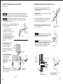
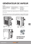
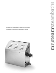
Installing the Remote Temperature Probe
Installing the Remote Temperature Probe (cont.)
for SAWO Controls
5. Route the end of the temperature probe cable with the
temperature probe through the wall into the steam room
as shown in Diagram 3.
CAUTION ! The Remote Temperature Probe is for use with SAWO Control only. Do not
use any other controls. Do not use any other temperature probe with the SAWO control.
Noncompatible products may result in an inoperative control and a hazardous condition.
CAUTION ! Install the SAWO Control according to the installation and operation
instructions supplied with the control. Failure to do so may result in an inoperative
control and a hazardous condition.
1. Determine the location of the Remote Temperature Probe.
The Remote Temperature Probe must be installed:
a. On a vertical surface
b. 1.2-1.5 meters above the floor
c. Away from the steam head
d. Not exposed to direct steam emission.
The probe has an integral 9 meter
cable. Insure that the probe and/or
steam generator are located accordingly.
Contact a SAWO technical service
representative if a longer cable is
required.
2. Drill an 8mm hole in the wall as
shown in Diagram 1. Do not
oversize or undersize the hole.
Clean area thoroughly.
3. Remove the knock-out from the
steam generator jacket as shown in
Diagram 2.
4. Insert the remote temperature
probe cable through the knockout and connect to the
connector on the steam
generator printed
circuit board marked "TEMP
PROBE" as shown
in Diagram 2.
IMPORTANT NOTE: Do not strain, staple, pinch or otherwise
damage the probe cable.
6. With a minimal length of the cable exposed apply silicone
(provided) to the hole in the wall as required to create a
moisture seal as shown in Diagram 3.
7. Push the temperature cable and bulb into hole as required
to leave minimum 6mm, maximum 13mm of the bulb
exposed as shown below.
Steam Room Interior
Diagram 3
WARNING ! Insure a minimum of 6mm of the temperature
bulb is exposed to the air. Failure to do so may result in an
inoperative control and a hazardous condition.
Diagram 1
WARNING ! The exposed area of the temperature bulb
mustbe free of silicone or any materials that prevent direct
exposure to the steam room air. Failure to do so may
interfere with the ability to sense temperature and may
result in excessive steam room temperatures.
Printed
Circuit
Board
Component
shown for
illustrative
purpose
Diagram 4
Temperature Probe
Connection
Knock-out
Temperature
Sensing Probe
6mm
Minimum
Silicone Sealant
13mm
Maximum
Temperature
Probe Cable
(9 meters)
KATSO
TÄRKE OHJEISTA
ÄT LISÄO
HJEET
LÄGG
VIKTIG MÄRKE TILL
DE
TILLÄGA
GSANV
ISNING
BEACH
ARNA
ZUSÄT TEN SIE
WICHTZLICHENDIE
ANWE IGEN
BEDIEISUNGEN
IN
NUNG
SANLEDER
READ
ITUNG
ADDIT THE MANU
AL FOR
INSTRIONAL IMPOR
UCTIO
TANT
NS
STR
230V
kW 1N~
NOTE:
For illustrative purposes only.
Consult. with qualified designer,
architect or contractor for steam
room construction details.
SAWO Steam Generator
(shown with cover removed and NOT installed)
DRAWING NOT
TO SCALE
Cable
Wall
SECTIONAL VIEW
INSTALLED REMOTE
TEMPERATURE PROBE
Diagram 2
16
17
SAWO Controls
Installation, Operation & Maintenance Manual
Step 5
Care Tips for Control
1. Use only mild soap and water on a soft cloth to clean the control.
2. Do not use abrasive cleansers
Remove & discard
peel-off paper to
expose adhesive
liner as shown.
CAUTION ! Do not route the control or temperature sensor wiring inside conduit
together with power lines or close to hot water or steam piping. Doing so may result in
Nhazardous installation. Do not alter or modify the control. Doing so may
an inoperative or
result in an inoperative or hazardous installation.
IMPORTANT NOTE: Turn power to the steam generator OFF before installing the control.
Failure to turn the power off will result in an inoperable control.
Installation Instructions
67 mm
Step 1
Determine the desired installation location of the control.
The SAWO control is designed to be installed inside or
outside the steam room as a matter of personal preference.
The control cable length is 7.5 m. Insure that the control
and/or steam generator are located accordingly.
25 mm
25 mm
A
Step 6
Run a bead of
silicone (provided)
as shown to the
C shaped groove as
shown.
IMPORTANT:
Do not apply
excessive amounts
of silicone.
Do not apply silicone
to any other parts of
the control including
the adhesive gasket.
Step 2
Step 7
Do not oversize or undersize the hole.
Insure the
mounting surface
is and dry as required
for good adhesion.
Apply silicone into
the hole in the wall
as required to create
a moisture seal.
Step 3
Route the control cable to the steam generator.
Connect the connector to the steam generator.
NOTE: The connector is keyed.
Wall
B
IMPORTANT: Do not strain, staple pinch or otherwise
damage the control cable. Route cable as required to
permit replacement.
Hold the
control and press
the control against
the wall until the
adhesive sticks and
holds firmly as shown.
Step 4
Turn on power to the steam generator and test the control
to verify correct connections. Test per the instructions.
Proceed with installation and verification of proper control
function.
Wall
Wing nuts
Holder plate
Wall
Keypad
Adhesive tape
Wall
C
IMPORTANT: Turn power to the steam generator OFF
before installing the control. Failure to turn the power
off will result in an inoperable control.
D
18
19
Connection of SAWO Control and Temperature
Sensor to PCB.
Display
Keys
On/Off Key
• ON/OFF Key is used to turn the steam generator on/off.
• Press On/Off key to turn steam generator on. Press a second time to turn steam
generator off.
• A built-in timer automatically shuts the steam generator off a predetermined period
of time after it has been started, unless the user does so manually.
SAWO Control
Temperature Sensor
• The "Display" indicates the Set Point temperature.
Temperature
Sensor
Pause Key
Pause key is used to turn the steam generator off momentarily.
Press Pause key to activate stand-by mode.
Press a second time to resume normal function.
The "Set Point" indicator will flash on the function panel when Pause feature is activated.
SAWO Control
Scroll Up & Scroll Down Keys
Up & Down arrow keys are used to set ambient temperature.
Pressing and holding keys will increase or decrease the current temperature setting.
KATSO
TÄRKEÄOHJEISTA
T LISÄO
HJEET
LÄGG
VIKTIG MÄRKE TIL
L DE
TILLÄGA
GSAN
VISNIN
BEACH
GARN
A
ZUSÄTZTEN SIE DIE
WICHTI LICHEN
GE
N
ANWE
ISUNG
BEDIEN
UNGSEN IN DER
ANLEI
READ
TUNG
ADDIT THE MANU
IONAL
AL
INSTRU
IMPOR FOR
CTION
TANT
S
STR
The new and desired temperature setting ("Set Point" value) will remain for 5 seconds
on the LED display as a confirmation of the new value you have selected.
230V
kW 1N
~
The "Set Point" indicator shows the desired temperature, NOT the actual temperature.
Temperature can be adjusted in 0.5 degree increments from 40 to 49ºC.
When ambient temperature is 0.5ºC lower than the Set Point, the heater automatically
comes on until the temperature reaches Set Point plus 0.5ºC.
20
21
manufactured by:
www.sawo.com
[email protected]
Subject to change without notice.