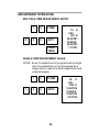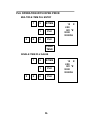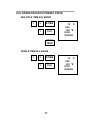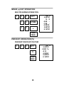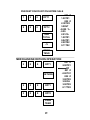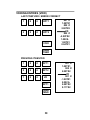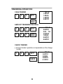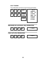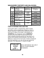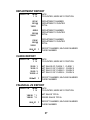
1
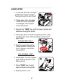
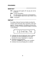
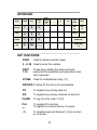
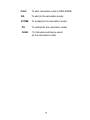
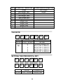
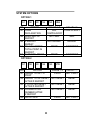
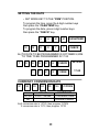
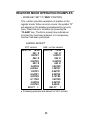
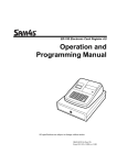
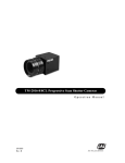
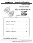
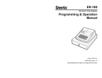
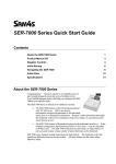
ER-180
OPERATION MANUAL
All specifications are subject to change without notice.
ATTENTION
The product that you have purchased contains a non- rechargeable Mn battery. This battery is recyclable. At the end of
its useful life, under various state and local laws, it may be illegal to dispose of the battery into the municipal waste
system.
Check with your local solid waste officials for details concerning recycling options or proper disposal.
WARNING
This is a Class A product. In a domestic environment this product may cause radio interference in which case the user
may be required to take adequate measures.
CAUTION
RISK OF EXPLOSION IF BATTERY IS REPLACED BY AN INCORRECT TYPE. DISPOSE OF USED BATERIES
ACCORDING TO THE INSTRUCTIONS.
Precaution Statements
Follow these safety, servicing and ESD precautions to prevent damage and to protect against potential hazards such as
electrical shock.
1-1
Safety Precautions
1. Be sure that all built-in protective devices are
replaced. Restore any missing protective shields.
2. When reinstalling the chassis and its assemblies,
be sure to restore all protective devices, including
nonmetallic control knobs and compartment
covers.
3. Make sure there are no cabinet openings through
which people - particularly children - might insert
fingers and contact dangerous voltages.
Such openings include excessively wide cabinet
ventilation slots and improperly fitted covers and
drawers.
4. Design Alteration Warning:
Never alter or add to the mechanical or electrical
design of the SECR. Unauthorized alterations
might create a safety hazard. Also, any design
changes or additions will void the manufacturer’s
warranty.
5. Components, parts and wiring that appear to have
overheated or that are otherwise damaged should
be replaced with parts that meet the original
specifications. Always determine the cause of
damage or over- heating, and correct any potential
hazards.
Observe the original lead dress, especially near the
following areas : sharp edges, and especially the
AC and high voltage supplies. Always inspect
for pinched, out-of-place, or frayed wiring. Do not
change the spacing between comp-onents and the
printed circuit board. Check the AC power cord
for damage. Make sure that leads and
components do not touch thermally hot parts.
7. Product Safety Notice:
Some electrical and mechanical parts have special
safety-related characteristics which might not be
obvious from visual inspection. These safety
features and the protection they give might be lost
if the replacement component differs from the
original - even if the replacement is rated for
higher voltage, wattage, etc.
Components that are critical for safety are
indicated in the circuit diagram by shading, ( )
Use replacement components that have
or ( ).
the same ratings, especially for flame resistance
and dielectric strength specifications. A
replacement part that does not have the same
safety characteristics as the original might create
shock, fire or other hazards.
CAUTION
Danger of explosion if battery is incorrectly replaced.
ATTENTION
ll y a danger d’explosion s’il y a remplacement incorrect
de la batterie.
Remplacer uniquement avec une batterie du même type
ou d’un type équivalent recommandé par le constructeur.
Mettre au rebut les batteries usagées conformément aux
instructions du fabricant.
Replace only with the same or equivalent type recommended by the manufacturer.
Dispose used batteries according to the manufacturer’s
instructions.
6.
SAFETY NOTICE : "For pluggable equipment, the socket-outlet shall be installed near
the equipement and shall be easily accessible."
1-2
Servicing Precautions
WARNING: First read the-Safety Precautions-section of this manual. If some unforeseen circumstance creates a
conflict between the servicing and safety precautions, always follow the safety precautions.
WARNING: An electrolytic capacitor installed with the wrong polarity might explode.
1. Servicing precautions are printed on the cabinet.
Follow them.
2. Always unplug the units AC power cord from the
AC power source before attempting to:
(a) Remove or reinstall any component or assembly
(b) Disconnect an electrical plug or connector
(c) Connect a test component in parallel with an
electrolytic capacitor
3. Some components are raised above the printed
circuit board for safety. An insulation tube or
tape is sometimes used. The internal wiring is
sometimes clamped to prevent contact with
thermally hot components. Reinstall all such
elements to their original position.
4. After servicing, always check that the screws,
components and wiring have been correctly
reinstalled. Make sure that the portion around the
serviced part has not been damaged.
1-3
5. Check the insulation between the blades of the AC
plug and accessible conductive parts
(examples : metal panels and input terminals).
6. Insulation Checking Procedure:
Disconnect the power cord from the AC source and
turn the power switch ON. Connect an insulation
resistance meter (500V) to the blades of AC plug.
The insulation resistance between each blade of the
AC plug and accessible conductive parts (see
above) should be greater than 1 megohm.
7. Never defeat any of the B+ voltage interlocks.
Do not apply AC power to the unit (or any of its
assemblies) unless all solid-state heat sinks are
correctly installed.
8. Always connect an instrument’s ground lead to the
instrument chassis ground before connecting the
positive lead ; always remove the instrument’s
ground lead last.
Precautions for Electrostatically Sensitive Devices (ESDs)
1. Some semiconductor (solid state) devices are easily
damaged by static electricity. Such components
are called Electrostatically Sensitive Devices
(ESDs); examples include integrated circuits and
some field-effect transistors. The following
techniques will reduce the occurrence of component
damage caused by static electricity.
2. Immediately before handling any semiconductor
components or assemblies, drain the electrostatic
charge from your body by touching a known earth
ground. Alternatively, wear a discharging wriststrap device. (Be sure to remove it prior to applying
power - this is an electric shock precaution.)
3. After removing an ESD-equipped assembly, place
it on a conductive surface such as aluminum foil to
prevent accumulation of electrostatic charge.
4. Do not use freon-propelled chemicals. These can
generate electrical charges that damage ESDs.
5. Use only a grounded-tip soldering iron when
soldering or unsoldering ESDs.
6. Use only an anti-static solder removal device.
Many solder removal devices are not rated as antistatic; these can accumulate sufficient electrical
charge to damage ESDs.
7. Do not remove a replacement ESD from its
protective package until you are ready to install it.
Most replacement ESDs are packaged with leads
that are electrically shorted together by conductive
foam, aluminum foil or other conductive materials.
8. Immediately before removing the protective
material from the leads of a replacement ESD,
touch the protective material to the chassis or
circuit assembly into which the device will be
installed.
9. Minimize body motions when handling unpackaged
replacement ESDs. Motions such as brushing
clothes together, or lifting a foot from a carpeted
floor can generate enough static electricity to
damage an ESD.
INITIAL SET UP INSTRUCTIONS
1
UNPACK THE CASH REGISTER ⋅⋅⋅⋅⋅⋅⋅⋅⋅⋅⋅⋅⋅⋅⋅⋅⋅⋅⋅⋅⋅⋅⋅⋅⋅⋅⋅⋅⋅⋅⋅⋅1
CLEAR RANDOM ACCESS MEMORY (RAM) AND
INITIALIZE CASH REGISTER ⋅⋅⋅⋅⋅⋅⋅⋅⋅⋅⋅⋅⋅⋅⋅⋅⋅⋅⋅⋅⋅⋅⋅⋅⋅⋅⋅⋅⋅⋅⋅⋅⋅⋅⋅⋅⋅⋅1
LOAD PAPER ⋅⋅⋅⋅⋅⋅⋅⋅⋅⋅⋅⋅⋅⋅⋅⋅⋅⋅⋅⋅⋅⋅⋅⋅⋅⋅⋅⋅⋅⋅⋅⋅⋅⋅⋅⋅⋅⋅⋅⋅⋅⋅⋅⋅⋅⋅⋅⋅⋅⋅⋅⋅⋅⋅⋅⋅⋅⋅⋅⋅⋅⋅⋅⋅⋅⋅2
HOW TO REPLACE THE INK ROLLER ⋅⋅⋅⋅⋅⋅⋅⋅⋅⋅⋅⋅⋅⋅⋅⋅⋅⋅⋅⋅⋅3
FEATURES
4
MODE KEY ⋅⋅⋅⋅⋅⋅⋅⋅⋅⋅⋅⋅⋅⋅⋅⋅⋅⋅⋅⋅⋅⋅⋅⋅⋅⋅⋅⋅⋅⋅⋅⋅⋅⋅⋅⋅⋅⋅⋅⋅⋅⋅⋅⋅⋅⋅⋅⋅⋅⋅⋅⋅⋅⋅⋅⋅⋅⋅⋅⋅⋅⋅4
DISPLAY ⋅⋅⋅⋅⋅⋅⋅⋅⋅⋅⋅⋅⋅⋅⋅⋅⋅⋅⋅⋅⋅⋅⋅⋅⋅⋅⋅⋅⋅⋅⋅⋅⋅⋅⋅⋅⋅⋅⋅⋅⋅⋅⋅⋅⋅⋅⋅⋅⋅⋅⋅⋅⋅⋅⋅⋅⋅⋅⋅⋅⋅⋅⋅⋅⋅⋅⋅⋅⋅⋅⋅⋅⋅⋅4
KEYBOARD ⋅⋅⋅⋅⋅⋅⋅⋅⋅⋅⋅⋅⋅⋅⋅⋅⋅⋅⋅⋅⋅⋅⋅⋅⋅⋅⋅⋅⋅⋅⋅⋅⋅⋅⋅⋅⋅⋅⋅⋅⋅⋅⋅⋅⋅⋅⋅⋅⋅⋅⋅⋅⋅⋅⋅⋅⋅⋅⋅⋅⋅⋅⋅⋅⋅⋅⋅⋅⋅5
KEY FUNCTIONS ⋅⋅⋅⋅⋅⋅⋅⋅⋅⋅⋅⋅⋅⋅⋅⋅⋅⋅⋅⋅⋅⋅⋅⋅⋅⋅⋅⋅⋅⋅⋅⋅⋅⋅⋅⋅⋅⋅⋅⋅⋅⋅⋅⋅⋅⋅⋅⋅⋅⋅⋅⋅⋅⋅⋅⋅⋅⋅5
PROGRAMMING
8
TAX, DECIMAL POINT INFORMATION ⋅⋅⋅⋅⋅⋅⋅⋅⋅⋅⋅⋅⋅⋅⋅⋅⋅⋅⋅⋅⋅8
DEPARTMENT LINK TO PLU ⋅⋅⋅⋅⋅⋅⋅⋅⋅⋅⋅⋅⋅⋅⋅⋅⋅⋅⋅⋅⋅⋅⋅⋅⋅⋅⋅⋅⋅⋅⋅⋅⋅⋅⋅8
DEPARTMENT/PLU STATUS ⋅⋅⋅⋅⋅⋅⋅⋅⋅⋅⋅⋅⋅⋅⋅⋅⋅⋅⋅⋅⋅⋅⋅⋅⋅⋅⋅⋅⋅⋅⋅⋅⋅⋅⋅⋅⋅⋅⋅⋅⋅8
TAX RATE⋅⋅⋅⋅⋅⋅⋅⋅⋅⋅⋅⋅⋅⋅⋅⋅⋅⋅⋅⋅⋅⋅⋅⋅⋅⋅⋅⋅⋅⋅⋅⋅⋅⋅⋅⋅⋅⋅⋅⋅⋅⋅⋅⋅⋅⋅⋅⋅⋅⋅⋅⋅⋅⋅⋅⋅⋅⋅⋅⋅⋅⋅⋅⋅⋅⋅⋅⋅⋅⋅⋅⋅⋅9
SETTING THE PERCENT (%) KEY ⋅⋅⋅⋅⋅⋅⋅⋅⋅⋅⋅⋅⋅⋅⋅⋅⋅⋅⋅⋅⋅⋅⋅⋅⋅⋅⋅⋅9
SETTING THE MACHINE NUMBER ⋅⋅⋅⋅⋅⋅⋅⋅⋅⋅⋅⋅⋅⋅⋅⋅⋅⋅⋅⋅⋅⋅⋅⋅⋅⋅⋅10
RECEIPT PRINT / JOURNAL PRINT ⋅⋅⋅⋅⋅⋅⋅⋅⋅⋅⋅⋅⋅⋅⋅⋅⋅⋅⋅⋅⋅⋅⋅⋅⋅⋅10
ROUNDING OPTION ⋅⋅⋅⋅⋅⋅⋅⋅⋅⋅⋅⋅⋅⋅⋅⋅⋅⋅⋅⋅⋅⋅⋅⋅⋅⋅⋅⋅⋅⋅⋅⋅⋅⋅⋅⋅⋅⋅⋅⋅⋅⋅⋅⋅⋅⋅⋅⋅⋅⋅⋅⋅⋅⋅10
TRAING MODE ⋅⋅⋅⋅⋅⋅⋅⋅⋅⋅⋅⋅⋅⋅⋅⋅⋅⋅⋅⋅⋅⋅⋅⋅⋅⋅⋅⋅⋅⋅⋅⋅⋅⋅⋅⋅⋅⋅⋅⋅⋅⋅⋅⋅⋅⋅⋅⋅⋅⋅⋅⋅⋅10
SYSTEM OPTIONS ⋅⋅⋅⋅⋅⋅⋅⋅⋅⋅⋅⋅⋅⋅⋅⋅⋅⋅⋅⋅⋅⋅⋅⋅⋅⋅⋅⋅⋅⋅⋅⋅⋅⋅⋅⋅⋅⋅⋅⋅⋅⋅⋅⋅⋅⋅⋅⋅⋅⋅⋅⋅⋅⋅11
OPTION 1 ⋅⋅⋅⋅⋅⋅⋅⋅⋅⋅⋅⋅⋅⋅⋅⋅⋅⋅⋅⋅⋅⋅⋅⋅⋅⋅⋅⋅⋅⋅⋅⋅⋅⋅⋅⋅⋅⋅⋅⋅⋅⋅⋅⋅⋅⋅⋅⋅⋅⋅⋅⋅⋅⋅⋅⋅⋅⋅⋅⋅⋅⋅11
OPTION 2 ⋅⋅⋅⋅⋅⋅⋅⋅⋅⋅⋅⋅⋅⋅⋅⋅⋅⋅⋅⋅⋅⋅⋅⋅⋅⋅⋅⋅⋅⋅⋅⋅⋅⋅⋅⋅⋅⋅⋅⋅⋅⋅⋅⋅⋅⋅⋅⋅⋅⋅⋅⋅⋅⋅⋅⋅⋅⋅⋅⋅⋅⋅11
SETTING THE DATE
12
CURRENCY CONVERSION RATE
12
REGISTER MODE OPERATIONS
13
CLERK SIGN ON/OFF ⋅⋅⋅⋅⋅⋅⋅⋅⋅⋅⋅⋅⋅⋅⋅⋅⋅⋅⋅⋅⋅⋅⋅⋅⋅⋅⋅⋅⋅⋅⋅⋅⋅⋅⋅⋅⋅⋅⋅⋅⋅⋅⋅⋅⋅⋅⋅⋅⋅⋅⋅⋅⋅14
NO SALE OPERATIONS ⋅⋅⋅⋅⋅⋅⋅⋅⋅⋅⋅⋅⋅⋅⋅⋅⋅⋅⋅⋅⋅⋅⋅⋅⋅⋅⋅⋅⋅⋅⋅⋅⋅⋅⋅⋅⋅⋅⋅⋅⋅⋅⋅⋅⋅14
NON ADD NUMBER ENTRIES ⋅⋅⋅⋅⋅⋅⋅⋅⋅⋅⋅⋅⋅⋅⋅⋅⋅⋅⋅⋅⋅⋅⋅⋅⋅⋅⋅⋅⋅⋅⋅⋅⋅⋅14
DEPARTMENT OPERATION ⋅⋅⋅⋅⋅⋅⋅⋅⋅⋅⋅⋅⋅⋅⋅⋅⋅⋅⋅⋅⋅⋅⋅⋅⋅⋅⋅⋅⋅⋅⋅⋅⋅⋅⋅⋅⋅15
SINGLE ITEM DEPARTMENT SALES ⋅⋅⋅⋅⋅⋅⋅⋅⋅⋅⋅⋅15
PLU OPERATION WITH OPEN PRICE ⋅⋅⋅⋅⋅⋅⋅⋅⋅⋅⋅⋅⋅⋅⋅⋅⋅⋅⋅⋅⋅⋅⋅16
MULTIPLE ITEM PLU ENTRY ⋅⋅⋅⋅⋅⋅16
SINGLE ITEM PLU SALES ⋅⋅⋅⋅⋅⋅⋅⋅⋅⋅⋅⋅16
PLU OPERATION WITH PRESET PRICE ⋅⋅⋅⋅⋅⋅⋅⋅⋅⋅⋅⋅⋅17
MULTIPLE ITEM PLU ENTRY ⋅⋅⋅⋅⋅⋅17
SINGLE ITEM PLU SALES ⋅⋅⋅⋅⋅⋅⋅⋅⋅⋅⋅⋅17
MINUS (−) KEY OPERATION ⋅⋅⋅⋅⋅⋅⋅⋅⋅⋅⋅⋅⋅⋅⋅⋅⋅⋅⋅⋅⋅⋅⋅⋅⋅⋅⋅⋅⋅⋅⋅⋅⋅⋅⋅⋅⋅18
PERCENT DISCOUNT OPERATION ⋅⋅⋅⋅⋅⋅⋅⋅⋅⋅⋅⋅⋅⋅⋅⋅⋅⋅⋅⋅⋅⋅⋅18
PERCENT DISCOUNT ON ITEM ⋅⋅⋅⋅⋅⋅⋅⋅⋅⋅⋅⋅⋅⋅⋅⋅⋅⋅⋅⋅⋅18
PERCENT DISCOUNT ON ENTIRE SALE ⋅⋅⋅⋅⋅19
MERCHANDISE RETURN OPERATION ⋅⋅⋅⋅⋅⋅⋅⋅⋅⋅⋅⋅⋅⋅⋅⋅⋅19
VOID OPERATION ⋅⋅⋅⋅⋅⋅⋅⋅⋅⋅⋅⋅⋅⋅⋅⋅⋅⋅⋅⋅⋅⋅⋅⋅⋅⋅⋅⋅⋅⋅⋅⋅⋅⋅⋅⋅⋅⋅⋅⋅⋅⋅⋅⋅⋅⋅⋅⋅⋅⋅⋅⋅⋅⋅⋅20
LAST ITEM VOID / ERROR CORRECT ⋅⋅⋅⋅⋅⋅⋅⋅⋅⋅20
PREVIOUS ITEM VOID ⋅⋅⋅⋅⋅⋅⋅⋅⋅⋅⋅⋅⋅⋅⋅⋅⋅⋅⋅⋅⋅⋅⋅⋅⋅⋅⋅⋅⋅⋅⋅⋅⋅⋅⋅⋅⋅⋅20
TENDERING OPERATION ⋅⋅⋅⋅⋅⋅⋅⋅⋅⋅⋅⋅⋅⋅⋅⋅⋅⋅⋅⋅⋅⋅⋅⋅⋅⋅⋅⋅⋅⋅⋅⋅⋅⋅⋅⋅⋅⋅⋅⋅⋅21
CASH TENDER ⋅⋅⋅⋅⋅⋅⋅⋅⋅⋅⋅⋅⋅⋅⋅⋅⋅⋅⋅⋅⋅⋅⋅⋅⋅⋅⋅⋅⋅⋅⋅⋅⋅⋅⋅⋅⋅⋅⋅⋅⋅⋅⋅⋅⋅⋅⋅⋅⋅⋅⋅⋅21
AMOUNT TENDERED ON CASH ⋅⋅⋅⋅⋅⋅⋅⋅⋅⋅⋅⋅⋅⋅⋅⋅⋅⋅⋅⋅21
CHECK TENDER ⋅⋅⋅⋅⋅⋅⋅⋅⋅⋅⋅⋅⋅⋅⋅⋅⋅⋅⋅⋅⋅⋅⋅⋅⋅⋅⋅⋅⋅⋅⋅⋅⋅⋅⋅⋅⋅⋅⋅⋅⋅⋅⋅⋅⋅⋅21
SPLIT TENDER ⋅⋅⋅⋅⋅⋅⋅⋅⋅⋅⋅⋅⋅⋅⋅⋅⋅⋅⋅⋅⋅⋅⋅⋅⋅⋅⋅⋅⋅⋅⋅⋅⋅⋅⋅⋅⋅⋅⋅⋅⋅⋅⋅⋅⋅⋅⋅⋅⋅⋅⋅⋅22
RECEIVED ON ACCOUNT (RA) OPERATION ⋅⋅⋅⋅⋅⋅⋅22
PAID OUT (PO) OPERATION ⋅⋅⋅⋅⋅⋅⋅⋅⋅⋅⋅⋅⋅⋅⋅⋅⋅⋅⋅⋅⋅⋅⋅⋅⋅⋅⋅⋅⋅⋅⋅⋅⋅⋅⋅⋅22
CURRENCY CONVERSION OPERATION ⋅⋅⋅⋅⋅⋅⋅⋅⋅⋅⋅⋅⋅⋅⋅⋅⋅⋅23
RECEIPT ON/OFF⋅⋅⋅⋅⋅⋅⋅⋅⋅⋅⋅⋅⋅⋅⋅⋅⋅⋅⋅⋅⋅⋅⋅⋅⋅⋅⋅⋅⋅⋅⋅⋅⋅⋅⋅⋅⋅⋅⋅⋅⋅⋅⋅⋅⋅⋅⋅⋅⋅⋅⋅⋅⋅⋅⋅⋅⋅⋅⋅⋅23
CALCULATOR OPERATION ⋅⋅⋅⋅⋅⋅⋅⋅⋅⋅⋅⋅⋅⋅⋅⋅⋅⋅⋅⋅⋅⋅⋅⋅⋅⋅⋅⋅⋅⋅⋅⋅⋅⋅⋅⋅⋅⋅⋅⋅⋅24
MANAGEMENT REPORTS AND BALANCING
25
CASH IN DRAWER DECLARATION ⋅⋅⋅⋅⋅⋅⋅⋅⋅⋅⋅⋅⋅⋅⋅⋅⋅⋅⋅⋅⋅⋅⋅⋅25
FINANCIAL DAILY REPORT ⋅⋅⋅⋅⋅⋅⋅⋅⋅⋅⋅⋅⋅⋅⋅⋅⋅⋅⋅⋅⋅⋅⋅⋅⋅⋅⋅⋅⋅⋅⋅⋅⋅⋅⋅⋅⋅⋅26
P-T-D GRAND TOTAL REPORT ⋅⋅⋅⋅⋅⋅⋅⋅⋅⋅⋅⋅⋅⋅⋅⋅⋅⋅⋅⋅⋅⋅⋅⋅⋅⋅⋅⋅⋅⋅⋅26
DEPARTMENT REPORT⋅⋅⋅⋅⋅⋅⋅⋅⋅⋅⋅⋅⋅⋅⋅⋅⋅⋅⋅⋅⋅⋅⋅⋅⋅⋅⋅⋅⋅⋅⋅⋅27
CLERK REPORT⋅⋅⋅⋅⋅⋅⋅⋅⋅⋅⋅⋅⋅⋅⋅⋅⋅⋅⋅⋅⋅⋅⋅⋅⋅⋅⋅⋅⋅⋅⋅⋅⋅⋅⋅⋅⋅27
FINANCIAL Z2 REPORT⋅⋅⋅⋅⋅⋅⋅⋅⋅⋅⋅⋅⋅⋅⋅⋅⋅⋅⋅⋅⋅⋅⋅⋅⋅⋅⋅⋅⋅⋅27
SYSTEM BALANCING ⋅⋅⋅⋅⋅⋅⋅⋅⋅⋅⋅⋅⋅⋅⋅⋅⋅⋅⋅⋅⋅⋅⋅⋅⋅⋅⋅⋅⋅⋅⋅⋅⋅⋅⋅⋅⋅⋅⋅⋅⋅⋅⋅⋅⋅⋅⋅⋅28
MAINTENANCE
28
INITIAL SET UP INSTRUCTIONS
The following instructions describe how to unpack and start
up the cash register.
UNPACK THE CASH REGISTER
1. Unpack and unwrap cash register.
2. Locate in the packing the following items.
* 1 roll of paper
* 1 rewind spindle (for journal tape)
CLEAR RANDOM ACCESS MEMORY (RAM) AND
INITIALIZE CASH REGISTER
1. Place mode key in S position.
2. Connect the AC plug into a power outlet while
pressing the ″00″ keys.
3. Then, RAM is cleared and cash register prints the
symbol ″........″.
NOTE : This is a one time only procedure to be
performed after the battery is installed.
DO NOT CLEAR RAM ONCE THE CASH
REGISTER IS PROGRAMMED. TO DO SO
WOULD CAUSE ALL PROGRAMS AND
TOTALS TO BE LOST.
1
LOAD PAPER
1. Cut or tear the end of a single
paper tape evenly for proper
feeding through the print head.
2. Place paper roll in the paper
holder and insert the paper
end straight into the paper
inlet of the printer.
3. Depress the ″FEED″ key until the paper catches and
advances through the printer.
4. If the paper does not feed through the printer, make
sure the paper was entered properly, insert end of
paper tape.
FEED
FOR RECEIPT ONLY...
5. Pass the paper through the
receipt window of the printer
cover. Replace over printer
compartment.
FOR JOURNAL ONLY...
6. Route paper over top of paper
guide insert in the slot of the
take-up spool.
7. Press ″FEED″ key to wind
paper securely onto spindle.
8. Replace printer cover.
2
HOW TO REPLACE THE INK ROLLER
The ink roller is a one-time article. Re-inking roller can cause
damage to the printer and void warranty. Do not re-ink. When
the print becomes faint, replace the ink roller as follows.
1. Remove the old roller by
lifting of it.
2. Fit the new ink roller
completely.
Lever
2
3
4
5
6
3
5
6
3
4
4
5
6
1
1
2 2 1
3
FEATURES
MODE KEY
OFF - Turns the cash register off. Any key can not be
accessed.
REG - To enter transaction.
X
- To read register reports and C-I-D declaration.
Z
- To read register reports and reset totals to zero.
PGM - To program.
DISPLAY
The display features fluorescent digits providing the
customer with information about operation of the cash
register. During operations, the display will show the
following symbols. All these symbols appear in position
1 of the display.
1 2 3 4 5 6 .7 8
C : Indicates the amount displayed is due in change.
= : Indicates the amount displayed is the a total.
- : Indicates the amount displayed is a negative.
E : Indicates an error condition.
Press the “CLEAR”key to clear error condition.
S : Indicates the amount displayed is a subtotal.
4
KEYBOARD
FEED
RETURN
VOID
CLEAR
PLU
7
8
4
5
X/TIME
(X)
9
6
CLERK
1
2
3
TAX
0
00
.
RCPT
ON/OFF
C/CON
V
1
5
9
13
2
6
10
14
3
-
7
-%
11
+%
NO
SALE
CALC
RA
(+)
PO
(-)
CHECK
CHARGE
15
SUBTOTAL
4
8
12
16
CASH/TEND
(=)
KEY FUNCTIONS
FEED
Used to advance printer paper.
0 - 9, 00 Used to enter the number.
DEPT
1-16
These keys classify the items sold and
memorize the quantities and amounts in their
own memories.
X/TIME
Used for multiplication entry. (X)
RETURN To allow for the return of merchandise
PO
To register any money paid out.
RA
To register any money received on account.
CLERK
To log in/out for clerk 1,2,3,4
PLU
−
To register PLU entries
To register an amount minus or coupon.
-%
To register a percent discount (-%)on an item
or on a sale.
5
+%
To register surcharge (+%) on an item or on
a sale.
VOID
To correct entries before a sale is finalized.
CLEAR
To clear incorrect entries made on the
numeric keys. Also to clear error conditions
and silence the error tone.
TAX
To program the tax rate in PGM mode.
Also to enter the rate of tax in external
straight tax method in R mode.
RCPT To toggle receipt on and off status
ON/OFF To use currency conversion function
C/CONV
NOSALE To print the reference number or to open
the cash drawer outside of a sale.
CHECK To finalize the transaction in check sales.
CHARGE To finalize the transaction in charge sales.
SUB
TOTAL
To obtain the subtotal of a sale.
CASH/TEND To finalize cash sale and change
calculation.
6
CALC
To start calculation mode in REG MODE.
RA
To add (In the calculation mode).
X/TIME
To multiply(In the calculation mode).
PO
To subtract(In the calculation mode).
CASH
To Calculate and display result
(In the calculation mode).
7
PROGRAMMING
Read this entire section carefully to program the machine to
the most preferable set-up according to your store system.
* MODE KEY POSITION : PGM *
TAX, DECIMAL POINT INFORMATION
N1
N1
N2
N2
X/TIME
VALUE
0 = 2 decimal
1 = non decimal
2 = 1 decimal
3 = 3 decimal
0 = VAT
1 = add-on tax
2 = external straight tax
DEPARTMENT LINK TO PLU
1~100
PLU
DEPT(Linked)
STATUS AND PRESET PRICE OF PLU &
DEPARTMENT
N2
N1
1~100
N3
PLU
N4
N5
N6
N7
N1,N2,N3,N4,N5,N6,N7,N8
N1 ~ N7 : Preset Price
N8
: STATUS
8
N8
DEPT
PLU
N8
0
1
2
3
4
5
6
7
8
9
In case VAT, add-on tax
Single
Non single, tax1
Non single, tax2
Non single, tax3
Non single,tax4
Single, non tax
Single, tax1
Single, tax2
Single, tax3
Single,tax4
In case external straight tax
Non single
Single
TAX RATE
N1
N2
N1-N5
N6
N3
N4
VALUE
0.000 - 99.999
0
1
2
3
4
N5
N6
COMMENTS
Tax rate
External straight tax
Tax1 (VAT or add-on)
Tax2 (VAT or add-on)
Tax3 (VAT or add-on)
Tax4 (VAT or add-on)
SETTING THE PERCENT(%) KEY
N1
N2
N3
N4
N5
-%
N1
N2
N3
N4
N5
+%
VALUE
N1-N5 0.000 - 99.999
COMMENTS
Percent rate
9
TAX
SETTING THE MACHINE NUMBER
N1
N2
NO SALE
2 DIGITS
RECEIPT PRINT / JOURNAL PRINT
N1
N1
N2
N2
VALUE
0
1
0
1
SUB
TOTAL
COMMENTS
Taxable, tax amount print
Taxable, tax amount not print
Receipt Mode
Journal Mode
ROUNDING OPTION
N1
−
N1
COMMENTS
0 European Rounding Not use
1 European Rounding Use
TRAIN MODE
N1
CHARGE
N1
COMMENTS
0 Normal Mode
1 Train Mode
10
SYSTEM OPTIONS
OPTION 1
N1
N2
N3
N4
NO
OPTION
N1 CASH
DECLARATION
N2 ZERO SKIP IN
REPORT
N3 Z REPORT
REPEAT
N4 RF / VD / GROSS
TOTAL PRINT IN
REPORT
N5 SUBTOTAL PRINT
N5
RA
VALUE = 0
VALUE = 1
NOT
COMPULSORY
COMPULSORY
NOT SKIP
SKIP
NOT REPEAT
REPEAT
PRINT
NOT PRINT
PRINT
NOT PRINT
OPTION 2
N1
N2
N3
N4
NO
OPTION
N1 GRAND TOTAL TO
PRINT
N2 GRAND TOTAL RESET
AFTER Z REPORT
N3 Z COUNTER RESET
AFTER Z REPORT
N4 CONSECUTIVE
NUMBER AFTER
Z REPORT
N5 DATE PRINT
11
N5
PO
VALUE = 0
PRINT
VALUE = 1
NOT PRINT
NOT RESET
RESET
NOT RESET
RESET
NOT RESET
RESET
PRINT
NOT PRINT
SETTING THE DATE
•
SET MODE KEY TO THE ″PGM″ POSITION.
To program the time, press the 4 digit number keys
then press the “CASH/TEND”key.
To program the date, press 6 digit number keys
then press the ″CHECK″ key.
M
M
H
H
M
M
CASH/TEND
D
D
Y
Y
CHECK
Ex) TO DATE TO BE PROGRAMMED IS OCTOBER 9,2006
TO TIME TO BE PROGRAMMED IS 17:25
1
0
0
9
0
6
CHECK
1
7
2
5
CASH
09-10-06
CURRENCY CONVERSION RATE
N1
N2
N1-N5
N6
N3
N4
N5
VALUE
0.000 - 99.999
N6
C/CONV
COMMENTS
Conversion Rate
Decimal Position
Ex)If conversion rate is 1.3720, then program 137204
If conversion rate is 13.72, then program 13722
12
17-25
REGISTER MODE OPERATION EXAMPLES
•
MODE KEY SET TO ″REG″ POSITION
This section provides examples of practice in the
register mode. When an error occurs, the symbol ″E″
will appear on the display accompanied by an error
tone. Clear this error condition by pressing the
″CLEAR″ key. The Error prompt may indicate an
incorrect key has been entered, or a compulsory
function has been performed.
SAMPLE RECEIPT
VAT version
02-01-10 14-30
001 #
1.00TX1
002 #
2.00TX2
003 #
3.00TX3
6.00CA
1.00TX1
0.04TX1
2.00TX2
0.11TX2
3.00TX3
0.22TX3
001-77 1
Add - on tax version
02-01-10 14-30
001 #
1.00TX1
002 #
2.00TX2
003 #
3.00TX3
1.00TX1
0.04TX1
2.00TX2
0.12TX2
3.00TX3
0.24TX3
6.40CA
001-77
1
• Following example are based on VAT version.
13
CLERK SIGN ON
CLERK
1
CLERK SIGN OFF
CLERK
0
NO SALE OPERATION
A no sales operation opens the cash drawer outside of
a sale. The financial report records the no sale activity
counter.
•••••••• NS
002-77
NO
SALE
NON ADD NUMBER ENTRIES
The ″#/NS″ key can be used to enter up 7 digits.
The entry can be made prior to any operation in the
register mode. This numeric entry will not add to any
activity counts or totals.
1
2
3
4
5
6
7
NO
SALE
12345.67
14
#
DEPARTMENT OPERATION
MULTIPLE ITEM DEPARTMENT ENTRY
2
1
5
X/TIME
0
0
DPT1
CASH
TEND
15 X
2.00
001 #
30.00TX1
30.00CA
30.00TX1
1.15TX1
SINGLE ITEM DEPARTMENT SALES
NOTE : Even if a department is programmed as single
item, the department is not processed as a
single sale in case of another department had
entered already.
1
1
0
X/TIME
0
0
DPT2
15
10 X
1.00
002 #
10.00TX2
10.00CA
10.00TX2
0.57TX2
PLU OPERATION WITH OPEN PRICE
MULTIPLE ITEM PLU ENTRY
1
2
0
5
X/TIME
1
PLU
0
PLU
15 X
2.00
001 *#
30.00
30.00CA
CASH
TEND
SINGLE ITEM PLU SALES
1
2
0
5
X/TIME
1
PLU
0
PLU
16
15 X
2.00
001 *#
30.00
30.00CA
PLU OPERATION WITH PRESET PRICE
MULTIPLE ITEM PLU ENTRY
1
5
X/TIME
1
PLU
15 X
2.00
001 *#
30.00
30.00CA
CASH
TEND
SINGLE ITEM PLU SALES
1
5
X/TIME
1
PLU
17
15 X
2.00
001 *#
30.00
30.00CA
MINUS (−) KEY OPERATION
MULTIPLE MINUS OPERATION
5
0
0
DPT1
1
5
X/TIME
5
0
−
001 #
5.00TX1
15 X
-0.50 -7.50 -2.50CA
5.00TX1
0.19TX1
CASH
TEND
PERCENT OPERATION (%)
PERCENT DISCOUNT ON ITEM
5
0
0
DPT1
-%
CASH
TEND
18
001 #
5.00TX1
-3.000 %-0.15
4.85CA
5.00TX1
0.19TX1
PERCENT DISCOUNT ON ENTIRE SALE
1
0
0
DPT1
2
0
0
DPT2
SUB
TOTAL
-%
001 #
1.00TX1
002 #
2.00TX2
3.00ST
-3.000 %-0.09
2.91CA
1.00TX1
0.04TX1
2.00TX2
0.11TX2
CASH
TEND
MERCHANDISE RETURN OPERATION
2
0
0
DPT1
RETURN
2
0
0
DPT1
3
0
0
DPT2
CASH
TEND
19
001 #
2.00TX1
••••••••RF
001 #
-2.00TX1
002 #
3.00TX2
3.00CA
3.00TX2
0.17TX2
VOIDING ENTRIES (VOID)
LAST ITEM VOID / ERROR CORRECT
1
0
0
DPT1
2
0
0
DPT2
VOID
001 #
1.00TX1
002 #
2.00TX2
••••••••VD
002 #
-2.00TX2
1.00CA
1.00TX1
0.04TX1
CASH
TEND
PREVIOUS ITEM VOID
1
0
0
DPT1
2
0
0
DPT2
1
0
0
VD
DPT1
CASH
TEND
20
001 #
1.00TX1
002 #
2.00TX2
••••••••VD
001 #
-1.00TX1
2.00CA
2.00TX2
0.11TX2
TENDERING OPERATION
CASH TENDER
1
0
0
DPT1
CASH
TEND
001 #
1.00TX1
1.00CA
1.00TX1
0.04TX1
AMOUNT TENDERED ON CASH
2
0
0
DPT1
3
0
0
CASH
TEND
001 #
2.00TX1
2.00 TA
3.00TX2
1.00CG
2.00TX1
0.08TX1
CHECK TENDER
• Amount tender operation is impossible on the charge
tender.
3
0
0
DPT1
CHECK
21
001 #
3.00TX1
3.00CH
3.00TX1
0.12TX1
SPLIT TENDER
The cash drawer should not open during split tender.
4
0
0
DPT1
2
0
0
CASH
TEND
CHECK
001 #
4.00TX1
4.00 TA
2.00TX2
2.00 TA
2.00 CH
4.00TX1
0.15TX1
RECEIVED ON ACCOUNT (RA) OPERATION
7
0
0
RA
7.00RA
PAID OUT (PO) OPERATION
5
0
0
PO
22
5.00PO
CURRENCY CONVERSION OPERATION
1
0
0
DPT1
C/CONV
1
3
7
2
CASH
RECEIPT ON/OFF
RCPT
ON/OFF
23
001 #
1.00
1.00 TA
13.72 @
1.00 PO
1.00TX1
0.04TX1
CALCULATOR OPERATION
Turn the mode key to “REG” MODE and press “CALC” key.
To exit from Calculator mode, Press “CLEAR” key or Turn
the mode key.
RA
:
PO
:
X/TIME
:
CASH/TEND :
+
X
=
CALC
1
0
0
RA
(+)
2
0
0
CASH
(=)
PO
(-)
1
5
CASH
(=)
0
X/TIME
(x)
1
0
0
CASH
(=)
100 + 200 = 300
- 150
= 150
x 100
= 15000
24
MANAGEMENT REPORTS AND BALANCING
MODE
REPORT
X
CASH IN
DRAWER
DECLARATION
X
FINANCIAL DAILY
Z
REPORT
X
P-T-D GRAND
TOTAL
Z
X
DEPARTMENT
Z
REPPORT
X
CLERK REPORT
Z
X
FINANCIAL
Z
Z2 REPORT
KEY
AMOUNT SUBTOTAL
COMMENTS
AMOUNT =
NUMERIC
CASH
TEND
CHECK
READ
READ & RESET
READ
READ & RESET
READ
READ & RESET
READ
READ & RESET
READ
READ & RESET
CHARGE
CLERK
VOID
CASH IN DRAWER DECLARATION
In the system option 1 programming, cash-in-drawer
declaration can be programmed compulsory. Cash-indrawer declaration is performed by adding the total of
each type of media in the drawer, and pressing the
″SUBTOTAL″ key. Depression of the ″SUBTOTAL″
key with numeric will enter the information that the
cash-in-drawer declaration performed, and reports in X
position and Z position will be allowed. In this case, the
difference of input amount and cash in drawer is displayed.
After this declaration, you can not take any registering
operation, if not reporting in X mode or Z mode.
02-01-10 14-30
180.00CA
184.26AT
-4.26
021-77 1
TOTAL ENTERED BY KEY-INPUT
TOTAL IN CASH DRAWER
DIFFERENCE
25
FINANCIAL DAILY REPORT
02-01-10
14-30
1 Z
54.00TX1
2.08TX1
19.00TX2
1.07TX2
3.00TX3
0.22TX3
3.00TX4
0.22TX4
-0.24 %0.20 %+
-7.50
188.26 * 1
-2.00RF
-3.00VD
198.00 * 2
018 #
183.26CA
5.00CH
0.00CG
7.00RA
5.00PO
184.26AT
001 NS
•••••••••
198.00 * 3
064−01 1
DATE
Z COUNTER, MODE KEY POSITION
TAXABLE1 TOTAL
TAX1 TOTAL
TAXABLE2 TOTAL
TAX2 TOTAL
TAXABLE3 TOTAL
TAX3 TOTAL
TAXABLE4 TOTAL
TAX4 TOTAL
-PERCENT TOTAL
+PERCENT TOTAL
(-) TOTAL
NET SALES TOTAL
RETURN MERCHANDISE TOTAL
VOID TOTAL
GROSS SALES TOTAL
CUSTOMER COUNTER
CASH TOTAL
CHECK TOTAL
CHARGE TOTAL
RECEIVED ON ACCOUNT
PAID OUT
CASH IN DRAWER
NO SALE COUNTER
GRAND TOTAL
RECEIPT NUMBER, MACHINE NO.
CLERK NUMBER
P-T-D GRAND TOTAL REPORT
001 *Z
198.00 *4
P-T-D GRAND TOTAL
26
DEPARTMENT REPORT
02-01-10
DATE
Z COUNTER, MODE KEY POSITION
14-30
1 X
001 #
003 @
19.00
DEPARTMENT NUMBER
DEPARTMENT COUNTER
TOTAL
002 #
002 @
29.00
DEPARTMENT NUMBER
DEPARTMENT COUNTER
TOTAL
DEPARTMENT NUMBER
DEPARTMENT COUNTER
TOTAL
016 #
005 @
20.00
064−01
1
RECEIPT NUMBER, MACHINE NUMBER
CLERK NUMBER
CLERK REPORT
02-01-10
DATE
Z COUNTER, MODE KEY POSITION
14-30
1 X
25.00
30.00
59.00
100.00
NET SALES OF CLERK 1 , CLERK 1
NET SALE S OF CLERK 2 , CLERK 2
NET SALE S OF CLERK 3 , CLERK 3
NET SALE S OF CLERK 4 , CLERK 4
1
2
3
4
064−01
1
RECEIPT NUMBER, MACHINE NUMBER
CLERK NUMBER
FINANCIAL Z2 REPORT
02-01-10
DATE
Z COUNTER, MODE KEY POSITION
14-30
1 X
NET SALES TOTAL
GROSS SALES TOTAL
188.26 * 1
198.00 * 2
064−01
1
RECEIPT NUMBER, MACHINE NUMBER
CLERK NUMBER
27
SYSTEM BALANCING
NET SALES TOTAL
= DEPARTMENT TOTALS
(add positive, subtract negative)
+ TAX TOTAL (add-on,
external straight tax version
only)
+ % TOTAL
+ (−) TOTAL
GROSS SALES TOTAL = NET SALES TOTAL
− MERCHANDISE RETURN
− (−) TOTAL
− % TOTAL
ENDING GRAND TOTAL = GROSS SALES TOTAL
+ PREVIOUS GRAND
TOTAL
MAINTENANCE
1. Avoid excess dust and extreme temperatures.
2. Be certain that AC cord is inserted firmly in the outlet,
and that cord poses no danger of accidental tripping.
3. Use no chemicals or abrasives while cleaning cabinet
or keyboard.
4. Do not pull or hold paper while the register is printing.
28
JK68-60180A