1
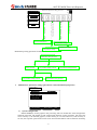
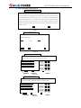
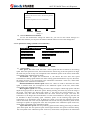
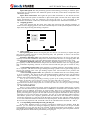
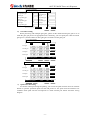
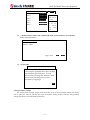
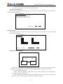
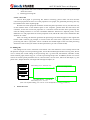
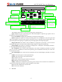
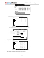
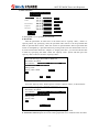
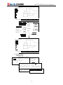
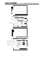
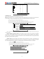
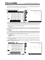
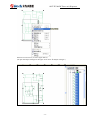
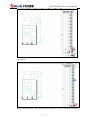
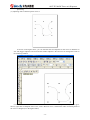
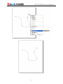
ADT-TP3340DJ
Three-axis Dispenser
User Manual
Adtech (Shenzhen) CNC Technology Co., Ltd.
Add: 5/F, 27-29/Bldg, Tianxia IC Industry Park, Yiyuan Rd, Nanshan District, Shenzhen
Postal code: 518052
Tel: 0755-26722719
Email: [email protected]
Fax: 0755-26722718
http://www.adtechcn.com
ADT-TP3340DJ Three-axis Dispenser
Copyright
Adtech (Shenzhen) Technology Co., Ltd. (Adtech hereafter) is in possession of
the copyright of this manual. Without the permission of Adtech, the imitation,
copy, transcription and translation by any organization or individual are
prohibited. This manual doesn’t contain any assurance, stance or implication in
any form. Adtech and the employees are not responsible for any direct or
indirect data disclosure, profits loss or cause termination caused by this manual
or any information about mentioned products in this manual. In addition, the
products and data in this manual are subject to changes without prior notice.
All rights reserved.
Adtech (Shenzhen) CNC Technology Co., Ltd.
-1-
ADT-TP3340DJ Three-axis Dispenser
Version History
Item No.
Version No.
Date of
Modification
Description
20070426
2.0
2009/9/29
2nd version
Remark: The three digits in the version No. have the following meanings:
Main version number of library
Secondary version number of library
Reserved
Note: The version history in the table above is only the update of the manual.
-2-
ADT-TP3340DJ Three-axis Dispenser
Contents
Chapter I. System Introduction ............................ - 4 Chapter II. Operation Instructions......................... - 4 I. Main Interface ...................................... - 4 VII. Operation method of double-station processing..... - 23 VIII. General operating flow .......................... - 23 Chapter III. Hardware Connection.......................... - 24 Appendix I. How to generate PLT files..................... - 27 1. Generating PLT files with CorelDRAW 12.............. - 27 2. Generating PLT files with AutoCAD2004............... - 28 3. Tips for CorelDRAW12 ............................... - 31 Appendix II. BootLoader Operation Instructions............ - 36 1. Introducing BootLoader program...................... - 36 2. Functions of BootLoader program..................... - 37 -
-3-
ADT-TP3340DJ Three-axis Dispenser
Chapter I. System Introduction
This system is suitable for the three-dimensional dispenser motion control system with four or less axes. It
supports single point and continuous dispensing; integrates linear, arc and elliptical interpolation function
in any space; copies a simple graph in matrix mode; integrates delay, output, designated glue gun, waiting
input and other instructions, facilitating customers to realize own special processes; enters coordinates in
manual or instruction mode, converts the CAD graphs in the computer to PLT files and saves in the
controller, and then converts to the processing files of the controller; integrates double-station processing
mode, and allows alternative processing of two stations; each file can save up to 10,000 processing points.
Chapter II. Operation Instructions
I. Main Interface
Station info area
工位信息显示区
Station I
Station II
Parameter settings
Not opened
Hardware test
Function
menu buttons
功能菜单按钮
File: w000
Points:
0000/0009
File management
Start point: Set
Start
Start
Edit file
Real-time
coordinates area
实时坐标显示区
Processing
state bar
加工状态显示条
Processing mode
State: Stop
Reset
Auto
Allow opening gun
Require resetting
Pause
Automatic dispensing
Stop
Processing
operation buttons
加工操作按钮
When the controller is electrified, it enters the main interface shown above, which consists of the
following contents:
1. Workstation info display area:
-4-
ADT-TP3340DJ Three-axis Dispenser
(Single station worktable)
(Double-station worktable)
This system supports two processing modes: single station and double stations. The information
of the processing file appears in workstation info display area.
Prompt: In “Manufacturer parameter settings” -> “System configuration”, you can select single
station or double-station for “Station number”. If double-station is selected, you also need to
select same Y-axis or different Y-axis in “Y-axis configuration for double-station” (if the Y-axes
of two stations act simultaneously, select “Same Y-axis”; if not, select “Different Y-axes”), and
then turn on/off a station in “Double-station switch” in User parameter settings“.
2. Processing state display bar:
The processing states include “Stop”, “Run”, “Pause”, “Reset”, “Emergency stop”, “Automatic
dispensing” and “Error”.
3. Real-time coordinates display area:
The unit is millimeter (mm), where U-axis is the coordinates of second Y-axis of double-station.
4. Processing operation buttons:
The operations such as start, reset, pause and stop have corresponding buttons;
For automatic dispensing function, you need to set the “Automatic tackless time” and “Automatic
tackless interval” in “User parameter settings” -> “Delay settings”. If one or two of the parameters are
set to 0, the automatic dispensing function is invalid.
The AUTO/Single Step button allows the controller running in automatic or single step mode. In
automatic mode, the program runs once from the start to the end and stops; in single step mode, the
program executes one instruction when you press the Start key. The single step function is mainly used
for files test.
5. Function menu buttons:
“Parameter settings” is used to set the parameters. Enter the password to access corresponding
interface, including manufacturer settings, user parameter settings, file parameter settings and
password management;
“Hardware test” is used for the test of the control system, including input, output and motor
control;
“File manager” is used to manage the files in local disk, mobile disk and remote device, and you
can perform operations like copy, delete, new file and preview.
II. Parameter settings
Enter the password to access the corresponding interface:
-5-
ADT-TP3340DJ Three-axis Dispenser
Please enter parameter setting password:
Parameter settings
Hardware test
File management
输入厂商设置密码
Password
management
密码管理
Enter admin password
Enter
file parameter setting
输入用户参数设置密码
setting
输入文件参数设置密码
Enter user parameter setting
Enter
manufacturer
输入管理员密码
Edit file
用户参数设置
User parameter settings
文件参数设置
File parameter
settings
Manufacturer
settings
厂商设置
Relationship among passwords of different levels:
厂商设置密码
Manufacturer setting password
Admin password
setting password
管理员密码User parameter
用户参数设置密码
User parameter用户参数设置密码
setting password
1.
File parameter setting password
文件参数设置密码
File parameter setting password
文件参数设置密码
Manufacturer parameter settings (parameters related mechanical properties)
Manufacturer
System configuration
Motor
Pulse equivalent
setting wizard
Save as default
Restore default
1)
Back
System configuration
Curve accuracy: All the graphs in the processing files are divided into small straight lines
and then processed. The length of split straight lines depends on this parameter. The lower the
curve accuracy is, the finer the graph is; on the contrary, it is coarser. However, if the accuracy is
too low, the response speed of the touch screen and external buttons will be affected. Generally,
-6-
ADT-TP3340DJ Three-axis Dispenser
the value is 50-100 times of the pulse equivalent of X-axis or Y-axis.
Reset test before running: If the option is set to 0, the program won’t perform reset test
before running and processes directly; if the option is set to other values, the program checks
whether the system has been reset before running and won’t allow processing if the system hasn’t
been reset.
Feeding mode: Available modes are Z-axis feeding and cylinder feeding. Z-axis feeding
indicates that Z-axis motor controls the advance and retreat of glue gun, while cylinder feeding
indicates that cylinder controls the advance and retreat of glue gun.
Station number: Select double-station or single station.
Double-station Y-axis configuration: If the Y-axes of two stations are controlled by one
motor, set this parameter to “Same Y-axis”; otherwise, set to “Different Y-axes”.
Default file edit view: Available options are guide view and list view, which can switch
between each other. Set this parameter to confirm the initial interface of edit view when starting
file editor.
Default processing point type: This parameter is used to set the type of processing point
when a new point is inserted into the processing file. If the “Single point” processing type
(dispensing) is used more frequently, please select “Single point”; if the “Linear” type is used
more frequently, please select “Linear”.
Admin password: Set the user parameter password and file parameter password with this
password.
User parameter password: Enter user parameter setting interface with this password.
File parameter password: Enter file parameter setting interface with this password.
2) Motor characteristics
First, what is pulse per revolution of the motor?
Pulse per revolution of the motor is the pulse that the controller sends when the motor runs
one circle. If it is step motor, you can calculate in the following method: pulse per revolution =
(360 ÷ step angle) × drive subdivision number. The step angle of our step motor is 1.8°. For the
subdivision number of drives, you can find a table on the drive, find the corresponding drive
subdivision number in the table according to the position of DIP switch, and then calculate the
pulse per revolution of the motor according to the formula above. If it is servo motor, calculate in
this formula: pulse per revolution = (encoder lines *4) * electronic gear ratio.
Pulse equivalent: The controller sends a pulse corresponding to the distance of motor
motion (unit: mm/pulse). If the motor moves 5mm after rotating one circle, the pulse per
revolution of the motor is 1000 and the pulse equivalent of the motor is:
Pulse equivalent = 5/1000=0.005;
Prompt: You can set the pulse equivalent of an axis with the “Pulse equivalent settings wizard” in
“User parameter settings”.
Reset mode: 0 indicates linear reset, such as screw rod, guide rail, etc. (no matter how many
circles there are, there is only one origin); other values indicate circle reset, such as turntable,
grinding wheel, etc. (one origin per revolution). In circle reset mode, the positive/negative values
of this parameter also can be used to confirm reset direction, positive values indicate reset in
positive direction and negative values indicate reset in negative direction (only for circle reset
mode; the linear mode always resets in negative direction).
Effective level of origin switch: The effective level of origin signal while resetting. The
external signals are in high level by default if no signal is connected.
Prompt: You can check the effective level of origin with “Hardware test” function. When the
motor is at the origin, if the corresponding input signal is highlighted, the effective level of the
origin signal is “Low”; otherwise, it is “High”.
Whether use origin limit: If yes, the motor can’t cross the origin in manual mode
Effective level of limit switch: If this parameter is set, the controller should be restarted to
make the new settings take effect.
Maximum stroke: During processing, if the stroke exceeds the set value, the excessive part
can’t be reached. If it is set to 0, there is no limit on maximum stroke.
Instruction direction: In the instruction interface, if the instruction direction is different
from the actual direction, please adjust the direction in this option.
Note: The instruction direction won’t affect the direction of motor test, automatic running
and resetting.
Minimum speed: The minimum speed (unit: Hz) when this axis moves
Maximum speed: The maximum speed (unit: Hz) when this axis moves
Maximum start speed: The minimum start speed (unit: Hz) when this axis moves
Minimum acceleration: The minimum acceleration (1-300) when this axis moves
Maximum acceleration: The maximum acceleration (1-300) when this axis moves
Prompt: The maximum start speed of common step motor is 180rpm, the maximum speed is
1200-1500rpm, and the optimal speed is 600-800rpm; the maximum start speed of servo motor is
300rpm and the maximum speed is 3000-5000rpm.
-7-
ADT-TP3340DJ Three-axis Dispenser
3)
Pulse equivalent setting wizard
Pulse equivalent setting wizard
Please make sure that you have read the user manual of this system and connect the
wires according to the wiring diagram. If the motor uses step drive, you need to set the
freewheeling and drive current of the drive. If it is servo drive, you need to understand
the basic condition of servo, such as encoder wires and electronic gear ratio of the servo.
Finally, please make sure that the motor is in an open position, and prepare a vernier
caliper. This wizard completes pulse equivalent setting by measuring certain length of
motor movement.
Next
Exit
(Step I)
Pulse equivalent setting wizard
Please select the axis (or axes) to complete pulse equivalent
setting through wizard.
X-axis
Y-axis
Previous
Z-axis
Next
Exit
(Step II)
Pulse equivalent setting wizard
Please move the motor to the first position (any position), and make sure
that the motor speed won’t cause the motor out of step.
X forward rotation/ X reverse rotation/ Speed:
Y forward rotation/ Y reverse rotation/ Speed:
Z forward rotation/ Z reverse rotation/ Speed:
Previous
Next
Exit
(Step III)
Pulse equivalent setting wizard
Please move the motor to the second position (keep far away from the
first position). Make sure that the motor won’t bump the limit.
X forward rotation/ X reverse rotation/ Speed:
Y forward rotation/ Y reverse rotation/ Speed:
Z forward rotation/ Z reverse rotation/ Speed:
Previous
Next
Exit
(Step IV)
-8-
ADT-TP3340DJ Three-axis Dispenser
Pulse equivalent setting wizard
Please measure the distance between the above two
positions, and enter the result in the following edit box
(unit: mm).
Actual moving distance of Y-axis: 100.0000mm
Previous
OK
Exit
(Step V)
4) Save as default/restore default
To save the manufacturer settings for future use, you can save the current settings in a
hidden file, and then you can press the “Restore default” button to restore the settings later.
3. User parameter settings (related to user functions)
User settings
Speed setting
Stop position
Delay setting
PLT conversion ratio
Correspondence between glue gun and pen
Gun offset setting
Quick file start setting
Double-station switch
Version info
Save as default
Restore default
1)
Back
Speed setting
Start speed: The motor must start with a lower speed and then accelerate to the running
speed. If the start speed is too low, the acceleration time will be long; if the start speed is too high,
the motor may be out of step. 0% corresponds to the “Minimum speed” of the motor, while 100%
corresponds to the “Maximum start speed”.
Acceleration: The higher the acceleration is, the shorter the time from start speed
accelerated to running speed and the time from running speed decelerated to stop are; otherwise,
the longer the time is. 0% corresponds to the “Minimum acceleration” of the axis, while 100%
corresponds to the “Maximum acceleration”.
Maximum/minimum manual speed: These two values are used to determine the motor
speed in manual mode. 0% corresponds to the “Minimum speed” of the axis, while 100%
corresponds to the “Maximum speed”.
Reset high/low speed: For resetting, the motor runs to origin in “Reset high speed” and then
adjust the origin position in “Reset low speed”. During resetting, the motor may cross the range of
the origin. The higher the “Reset high speed” is, the longer the crossed distance is. The
acceleration may also affect the distance that the motor crosses the origin. The lower the
acceleration is, the longer the crossed distance is. If the crossed distance is too long, the time will
be extended to adjust accurately again. Therefore, please set the resetting high speed and
acceleration to an appropriate value. If “Reset low speed” is too high, the adjustment precision
will be decreased; if it is too low, the adjustment time will be too long. Therefore, please set the
resetting low speed to an appropriate value. 0% corresponds to the “Minimum speed” of the axis,
while 100% corresponds to the “Maximum speed”.
Space shift start speed: The fast positioning speed of motor during processing is called as
space shift speed. The start speed of space shift is higher than the start speed of normal running.
0% corresponds to the “Minimum speed” of the axis, while 100% corresponds to the “Maximum
-9-
ADT-TP3340DJ Three-axis Dispenser
start speed”.
Space shift speed: The fast positioning speed of motor during processing is called as space
shift speed. 0% corresponds to the “Minimum speed” of the axis, while 100% corresponds to the
“Maximum speed”.
Space shift acceleration: The higher the space shift acceleration is, the shorter the time
from “Space shift start speed” accelerated to “Space shift speed” and the time from “Space shift
speed” decelerated to stop are; otherwise, the longer the time is. 0% corresponds to the
“Minimum acceleration” of the axis, while 100% corresponds to the “Maximum acceleration”.
2) Stopping position
This is the position that the motor stops when the processing file running completes. If
certain axis has stopping position, the motor automatically runs to the specified position and then
stops when the processing file running completes.
Stop position setting (press to select)
X-axis
Instruction
Y-axis
Instruction
Z-axis
OK
Cancel
3)
Delay setting
Gun replacing time: When several glue guns are used, if it is necessary to replace the glue
gun (specify another glue gun in next processing file), this parameter is used to set the time
required to replace glue gun.
Automatic dispensing time: The automatic dispensing function is to turn on the glue gun
regularly to make the colloid flow and prevent concretion when the motor is in stopping state. The
“Automatic dispensing time” is the time duration when the glue gun is turned on every time.
Automatic dispensing interval: The automatic dispensing function is to turn on the glue
gun regularly to make the colloid flow and prevent concretion when the motor is in stopping state.
The “Automatic dispensing interval” is the time interval when the glue gun is turned on every
time.
* Gun feeding in-place time: This parameter is available when the “Gun feeding mode” is
set to “Cylinder”. The time from the gun feeding/retreating cylinder receives gun feeding signal to
arriving gun feeding point is the gun feeding in-place time. The machine won’t perform next
action before the delay.
* Gun retreating in-place time: This parameter is available when the “Gun feeding mode”
is set to “Cylinder”. The time from the gun feeding/retreating cylinder receives gun retreating
signal to arriving gun retreating point is the gun retreating in-place time. The machine won’t
perform next action before the delay.
Note: If the external gun feeding/retreating signals of the feeding/retreating cylinder are
available, the machine will perform next action even if the delay time isn’t arrived.
Special usage: If the gun feeding or retreating delay is set to 0, it indicates that no delay is
applied and the machine will perform next action only when the external gun feeding/retreating
in-place signals are effective.
4) PLT conversion ratio
PLT is a vector graphics file format, which can describe the graphic characteristics of plane
figure. This file format can be generated with CorelDRAW or AutoCAD. The coordinate units in
PLT file may be different from those in actual graphs. They have a proportion relationship.
Before converting the PLT file to processing file, it is necessary to set this parameter in order to
get the processing file in proper size. PLT file conversion proportion should be set when the pulse
equivalent of every axis has been set properly. You can set in the following method: Draw a
100×100mm square in the computer, generate PLT file and send to the controller, set the PLT
conversion proportion to 1 and convert the PLT file to processing file, enter the editing interface
to view the coordinates difference between two adjacent points, set the difference to L and proper
PLT conversion proportion to K, and the K value can be calculated in this formula: K = 100÷L.
5)
Corresponding relationship between gun and pen
In PLT files, different colors (or layers) correspond to different pen numbers. With this
function, you can realize the multi-gun dispensing function. You need to set the pen number
corresponding to every glue gun first, for example, if black corresponds to pen number 1, set the
pen number corresponding to first glue gun to 1, and thus the first glue gun corresponds to black.
The graphs drawn in black will be processed by first glue gun.
- 10 -
ADT-TP3340DJ Three-axis Dispenser
Glue gun/pen correspondence settings
First gun
Fifth gun
Corresponding pen
Corresponding pen
Second gun
Sixth gun
Corresponding pen
Corresponding pen
Third gun
Fourth gun
Corresponding pen
Corresponding pen
Fourth gun
Corresponding pen
Eighth gun
Corresponding pen
Page: 01/01
Cancel
OK
6)
Gun offset setting
When processing with multiple glue guns, please set the offset between glue guns so as to
make the glue gun process in appropriate track. Generally, you can specify the offset of certain
glue gun to 0, and the offsets of other glue guns are relative to this glue gun.
Gun offset settings
X-axis
Z-axis
Instruction
First gun
Second gun
Instruction
Third gun
Instruction
Instruction
Fourth gun
Reference point
Next
OK
Back
Gun offset settings
X-axis
Y-axis
Z-axis
First gun
Instruction
Second gun
Instruction
Third gun
Instruction
Fourth gun
Instruction
Reference point
Next
OK
7)
Back
Quick start file setting
To call out certain processing file quickly, you can use the quick start file. Press an external
button to open the specified quick start file and process it. Six quick start file interfaces are
available. Each quick start file corresponds to a fixed external port. Please check the wiring
diagram.
- 11 -
ADT-TP3340DJ Three-axis Dispenser
Quick start file setting
OK
File 1: Graph 1
Select file
File 2:
Select file
File 3:
Select file
File 4
Select file
File 5:
Select file
File 6:
Select file
Back
If
the
file
name is null, it
is invalid.
The quick start
file only can
be
selected
from
\PRG
folder.
8)
* Double-station switch (only available when the station number is set to double)
Enable and disable station.
Double-station settings
Station 1: Open
Station 2: Open
Page: 01/01
9)
OK
Cancel
Version info
Software version: V4.1
Main program generating date: April 10, 2008
Main program generating time: 11:20:21
Kernel code generating date: March 27, 2008
Kernel code generating time: 16:38:43
Prepared by: tanggongyi
Back
4. File parameter settings
For file parameter settings, please select the station to be set first (click the station info display
area to select the station), and then press the “Parameter setting” button, enter the file parameter
setting password to enter the following interface:
- 12 -
ADT-TP3340DJ Three-axis Dispenser
Station I file parameter settings
File parameter setting
Glue gun usage setting
Station I processing start setting
Save as default
Restore default
Back
1)
File parameter setting
Start dispensing speed: During processing, the running speed when the glue gun is opened
is the dispensing speed, and the speed when the glue gun isn’t opened is the space shift speed (or
quick orientation speed). The motor must start with low speed and then accelerate to the running
speed. If the start speed is too low, the acceleration time will be long; if the start speed is too high,
the motor may be out of step. 0% corresponds to the “Minimum speed” of the motor, while 100%
corresponds to the “Maximum start speed”.
Dispensing acceleration: The higher the acceleration is, the shorter the time from start
speed accelerated to running speed and the time from running speed decelerated to stop are;
otherwise, the longer the time is.
Dispensing speed: During processing, the running speed when the glue gun is opened is the
dispensing speed, and the speed when the glue gun isn’t opened is the space shift speed (or quick
orientation speed). 0% corresponds to the minimum speed of XY-axis, while 100% corresponds
to the maximum speed of XY-axis.
Gun opening delay: The time (unit: sec) from the glue gun receiving open signal to totally
opened
Gun closing delay: The time (unit: sec) from the glue gun receiving close signal to totally
closed
Advance closing distance: After dispensing, close the glue in advance to avoid glue
accumulated in the stopping position.
Processing quantity setting, automatic process interval: When the specified quantity has
been processed, the machine stops processing automatically, and continues processing
automatically if not. The interval is determined by the automatic processing interval.
Automatic resetting times setting: After processed specified times, the motor resets to
eliminate accumulated error.
Present quantity: Present processing quantity; when this quantity reaches specified value,
the machine stops and resets automatically.
Present total output: The accumulated output
2)
Glue gun operation setting
In each station, you can set the glue guns opened in initial state by setting the glue gun to
“Use”.
Station I glue gun setting
Glue gun I: Use
Glue gun II: Not use
Glue gun III: Not use
Glue gun IV: Not use
Glue gun V: Not use
Glue gun IV: Not use
Glue gun IIV: Not use
Glue gun IIIV: Not use
Page: 01/01
3)
OK
Cancel
Start processing point setting
After editing a file, if you find that the running track of certain station has overall shift from
required track, you can solve this problem by setting the start processing point, i.e. correspond the
set start point to the first processing point of the processing file, and shift other processing points
according to this offset. If two stations have same offset, you can use the “Modify” function in
instruction view.
- 13 -
ADT-TP3340DJ Three-axis Dispenser
Note: Generally, do not edit the processing points of the file after setting the start point. If it
is necessary to edit, please cancel the setting of start point.
4. Password management
This function requires admin password. You can modify the user parameter setting password and file
parameter setting password.
Password management
User parameter setting password
File parameter setting password
*
Page: 01/01
OK
Cancel
III. File manager:
File manager consists of options such as open, copy, delete, new, preview, PLT conversion and USB
connection to computer.
File manager
Open
New
Delete
Copy
PLT conversion
USB connection
Station I: 123.DJJ
Station switch
Back
USB connection to computer
USB communicating……
Idle
Free
Exit
Restart
This function is mainly used for USB communication between controller and computer. Connect
to computer in USB mode and access the controller through computer. The main functions are:
1) Update controller program
Step 1: Copy the program file “adtrom.bin” to the “\ADT\” directory of the controller (the
file name only can be “adtrom.bin”)
Step 2: Restart the controller and press and hold the touch screen to call out “System start
interface”. Select “Update program” to update the controller program.
- 14 -
ADT-TP3340DJ Three-axis Dispenser
2)
3)
Copy the PLT file to the controller, and then convert the PLT file to processing file through
“PLT conversion”.
Back up processing file
5. PLT conversion
Convert PLT graph to processing file. Before converting, please make sure that the PLT
conversion proportion has been set. If the proportion isn’t proper, the generated processing file may
have different size from required graph.
PLT file conversion proportion should be set after the pulse equivalent of every axis has been set,
in this method: Draw a 100×100mm square in the computer, generate PLT file and send to the
controller, set the PLT conversion proportion to 1 and then convert the PLT file to processing file,
enter the editing interface to view the coordinates difference between two adjacent points, set the
difference to L and proper PLT conversion proportion to K, and the K value can be calculated in this
formula: K = 100/L.
After converting, the PLT file generates the processing with same file name as the original file
but has “DJJ” extension, for example, to convert a PLT file in the name “图样.PLT”, the converted
processing file will be “图样.DJJ”. The Z coordinate and needle height of the converted processing
file haven’t been set and you need to set these parameters (you can set in batch edit).
IV. Editing file:
File editing has two views: instruction view and list view. The instruction view is mainly used to edit
the position of single or several processing points, and set the needle height and time of every point; the list
view is mainly the overall editing of the processing file, e.g. batch edit, batch delete, automatic round,
insert common graph, matrix copy, etc., as well as processing file preview. In addition, the list view can be
used to set certain special parameters for arc, forward circle, reverse circle, full circle and ellipse, e.g. the
plane of arc, ellipse direction, start angle and end angle of ellipse, etc.
Parameter settings
Default
editing view is “Instruction view”
默认编辑视图为“教导视图”
Instruction view editing interface
教导视图编辑界面
Hardware test
File management
Edit file
List view editing interface
列表视图编辑界面
默认编辑视图为“列表视图”
Default
editing view is “List view”
(Note: The default editing view can be set in manufacturer settings parameter)
1.
Instruction view
- 15 -
ADT-TP3340DJ Three-axis Dispenser
Display the parameters of
No. Type
X coordinates Y coordinates
processing point
加工点各项参数显示
Z coordinates
Start point
Processing point switch
Speed:
Single point time:
Needle
height:
button
加工点切换按钮
Manual
motor control button
电机手动控制按钮
Manual
high/low speed
手动高低速
切换按钮
switch button
Save current coordinates in
将当前坐标保存
current 到当前加工点中
processing point
Save current Z-axis coordinates as the
将当前Z轴坐标保存
needle height of为当前加工点针高
current processing point
Low speed
Real-time coordinates display
实时坐标显示
Total points:
Set coordinates
Insert
Set needle height Go Here GoNext
Delete
Insert 在当前位置插入一个加工点
a processing point into current
position
Modify
Save
List
Exit
Modify the coordinates of a batch of
Switch
to list view
切换到列表视图
Move
to
current
运动到当前加工点
和下一个加工点
processing
point and
next processing point
修正一批加工点的坐标
processing
points
Delete current processing
删除当前加工点
point
No.: Display the number of current processing point, counting from 1.
Type: Display the type of processing point. For the description of specific type, please refer to
the details of every processing point type.
X, Y, Z coordinates: Display the coordinates of current processing point.
Speed: Display the speed of current processing point. 0% corresponds to the start speed and
100% corresponds to the processing speed. If the glue gun isn’t opened, the processing speed is the
space shift speed. If the glue gun is opened, the processing speed is the dispensing speed.
Single point time: This option is only available for “single point” processing, i.e. the time from
opening the glue gun to closing, used to adjust the glue output of single point dispensing.
Needle height: This option is available for “Single point”, “End point” and “Ellipse parameter”,
i.e. the height lifted when the glue gun is closed.
Set coordinates: Save current XYZ coordinates in the XYZ coordinates parameter of current
point. To save the coordinates of certain axis separately, press and hold the data entry box of the axis
for at least one second.
Set needle height: Save current Z-axis coordinates into the “Needle height” parameter of current
point.
GoHere: The motor goes to current point directly.
GoNext: The motor goes to next point directly.
List: Switch to list view.
Insert: Insert a processing point before current point.
Delete: Delete current processing point.
Modify: Modify the coordinates of processing points with the error between the coordinates of
current processing point and actual current coordinates as the offset.
Save: Save the modification of current file.
Exit: Exit to main interface.
2.
List view
- 16 -
ADT-TP3340DJ Three-axis Dispenser
Insert/ Instruction/ Delete/ Save/ Other
Type: X coordinates; Y coordinates; Z coordinates; Speed: More
Start point
Linear
Forward circle
End point
Line: 0004/0004
Up
Prompt: Gun closed
Down
Copy
Preview
Back
1) Preview: Select a point in the graph interface.
Magnification:0.94
Zoom in
Zoom out
Suitable
Left
Right
Up
Down
Point No.:0004
Previous point:
Next point:
Select
Back
2) Copy (matrix): Copy certain part of the graph in matrix mode.
Copy range: Start line:
X direction group number:
End line
Y direction group number:
X direction spacing:
Y direction spacing:
Instruction space
Prior offset axis: X
Z shape or S shape: S
Inserting mode: Append to the end
OK
Cancel
The graph after copied in matrix mode follows:
Magnification:0.94
Zoom in
Zoom out
Suitable
Left
Right
Up
Down
Point No.:0004
Previous point:
Next point:
Select
After copying, you can also modify certain points separately.
- 17 -
Back
ADT-TP3340DJ Three-axis Dispenser
3) Other functions
Insert/ Instruction/ Delete/ Save/ Cancel
Type: X coordinates
Start point
Common graphs
Go to line
Linear
Start point setting
Forward circle
Batch edit
End point
Batch delete
Start point
Line:0001/0024
Up
Automatic round
Down
a. Go to point: Go to specified point and edit.
b. Batch edit:
Edit the parameters in multi lines in the mode such as “Specify value”, “Scale” or
“Specify offset”. By specifying value, the specified value will be set to the specified data
field of specified data section, while the content of specified data field of specified data
section is multiplied by a specified fraction by scaling mode (note: the denominator can’t be
0). If the selected data field isn’t “Output” or “Single point time”, you can also edit the data
in batch by specifying the offset. Select the “Specify value” option and then press the
“Specify value” button to switch to “Specify offset”.
Batch edit data range: From 0001 to 0024 line
Data field to be edited:
X coordinates
Y coordinates Z coordinates
Single point time
Needle height
Editing mode:
Specify value 0.0000
Instruction
Scale
OK
Speed
Cancel
Press the “Specify value” button again to switch to “Specify offset”, as shown below:
Batch edit data range: From
to
line
Data field to be edited:
X coordinates
Y coordinates Z coordinates
Single point time
Needle height
Editing mode:
Specify value
Instruction
Scale
OK
Speed
Cancel
c. Batch delete: Delete the processing points in specified range in batch.
d. Automatic round: Replace the corners of the graph with arcs to make the track smoother.
- 18 -
ADT-TP3340DJ Three-axis Dispenser
Magnification:1.35
Zoom in
Zoom out
Suitable
Left
Right
Up
Down
Point No.:0001
Previous point:
Next point:
Select
Back
Insert/ Instruction/ DeleteRound range:
Type: X coordinates
Start line:
End line:
Specify glue gun
Start point
End point
Rounding
Specify glue gun
radius:
Start point
Restore file
OK
Line:0001/0025
Up
Cancel
Down
Magnification:1.43
Zoom in
Zoom out
Suitable
Left
Right
Up
Down
Point No.:0001
Previous point:
Next point:
Select
Back
e. Common graphs:
Running track
Please confirm the direction of long sides of the running track:
Front/back
Left/right
Position of two long sides of instruction:
A side
B side
Move to the center line position of two long sides: Move
Instruction arc ends position: C end
Confirm start point: A center point
D end
Confirm direction: Clockwise
Generate graph
- 19 -
Cancel
ADT-TP3340DJ Three-axis Dispenser
Magnification:1.04
Zoom in
Zoom out
Suitable
Left
Right
Up
Down
Point No.:0001
Previous point:
Next point:
Select
Back
Single point matrix
Start point
Instruction
X direction number:
Y direction
number:
Offset setting mode: Specify coordinates
Instruction
The 0006 th point in X direction X coordinates:
The 0010 th point in Y direction Y coordinates:
Instruction
First offset axis: X-axis
Z shape or S shape: Z
Generate graph
Cancel
Magnification:0.79
Zoom in
Zoom out
Suitable
Left
Right
Up
Down
Point No.:0001
Previous point:
Next point:
Select
Back
Rounded rectangle
Instruction
Left side position of the rectangle:
Right side position of the rectangle:
Instruction
Top side position of the rectangle:
Instruction
Bottom side position of the rectangle:
Instruction
Rounding radius:
Start point position: Left side center
Moving direction: Clockwise
Generate graph
- 20 -
Cancel
ADT-TP3340DJ Three-axis Dispenser
Magnification:0.87
Zoom in
Zoom out
Suitable
Left
Right
Up
Down
Point No.:0001
Previous point:
Next point:
Select
Back
V. Hardware test
Test the motor, output point and input point of every axis.
Motor test: Select the axis to be moved, and then select high speed or low speed, press the forward or
reverse button to select the running direction of motor, and release the button to stop the motor.
X origin/ Y origin/ Z origin/ U origin/ Stop/ Open/close gun
Start 1/ Start 2/ X positive limit/ X negative limit/ Y positive limit/ Y negative limit
Z positive limit/ Z negative limit/ U positive limit/ U negative limit/ X forward rotation/ X reverse rotation
Y forward rotation/ Y reverse rotation/ Z forward rotation/ Z reverse rotation/ Speed switch/ D123
X-axis
Y-axis
Z-axis
Low speed
Relative position/ Output control
High speed
U-axis
Forward rotation
Reverse rotation
OK
Back
Note: The direction that the motor approaches to the origin is negative and the direction leaving the
origin is positive.
Usage of “Relative position” button: If the “Relative position” button isn’t pressed, the coordinates
of each axis are the coordinates relative to origin, and can be called as absolute coordinates. If the “Relative
position” button is pressed, the coordinates of each axis are the coordinates relative to the position where
the “Relative position” button is pressed.
Output control: Press the Output control button to enter the interface, in which 16 output buttons are
available, corresponding to the output control of port 0-15 respectively. To control an output port, just press
the corresponding button. The output is on when the button is pressed and off when it is released.
X origin/ Y origin/ Z origin/ U origin/ Stop/ Open/close gun
Start 1/ Start 2/ X positive limit/ X negative limit/ Y positive limit/ Y negative limit
Z positive limit/ Z negative limit/ U positive limit/ U negative limit/ X forward rotation/ X reverse rotation
Y forward rotation/ Y reverse rotation/ Z forward rotation/ Z reverse rotation/ Speed switch/ D123
First gun/ Second gun/ Third gun/ Fourth gun
Motor control
Fifth gun/ Sixth gun/ Seventh gun/ Eighth gun
Replace gun 1/ Replace gun 2/ Replace gun 3/ Replace gun 4
Replace gun 5/ Replace gun 6/ Replace gun 7/ Replace gun 8
OK
Back
- 21 -
ADT-TP3340DJ Three-axis Dispenser
Input test: The top four lines display the state of input ports no matter in motor test interface or output
control interface. The normal display indicates no input signal, while the highlighted display indicates
input signal, e.g. the “Z origin” in above figure is highlighted.
VI. Description of processing point types
Magnification:0.26
Insert/ Instruction/ Delete/ Save/ Other
3
Zoom in
Type: X coordinates; Y coordinates; Z coordinates; Speed: More
2
Zoom out
Single point
4
1
Suitable
5
Start point
Left
Linear
Arc
Right
End point
Up
Line: 0005/0005
Up
Down
Down
Prompt: Gun closed
Copy
Preview
Back
Point No.:0001
Previous point:
Next point:
Select
Back
As shown in the figure above, the first point is “Single point”. During processing, Z-axis feeds gun at
this point and the gun feeding position is the Z-axis coordinates of this point. When the gun feeding
is in place, the machine starts dispensing, and closes the glue gun after specified “Single point time”
and then retreats glue gun to “Needle height” position.
1. Start point
As shown in the figure above, the second point is “Start point”. During processing, Z-axis feeds
gun at this point and the gun feeding position is the Z-axis coordinates of this point. When the gun
feeding is in place, the machine starts dispensing, and moves to next point after the specified “Gun
opening delay”.
2. End point
As shown in the figure above, the fifth point is “End point”. After moving to this point, the glue
gun is closed, and Z-axis returns to the “Needle height” position after the specified “Gun closing
delay”. Please note that the processing type of “End point” allows setting closing glue gun in advance
or not (in instruction view). If advance closing is set, the glue gun will be closed when it is in
“Advance gun closing distance” from the coordinates of end point.
3. Straight line
As shown in the figure above, the third point is “Straight line”, indicating moving to this point in
straight line mode.
4. Arc
As shown in the figure above, the fourth point is “Arc”, indicating moving to next point through
this point in arc mode. The arc processing point type determines an arc through three points on the arc.
5. Forward/reverse circle
The forward/reverse circles are similar to arc point. The difference is that forward/reverse circles
provide the coordinates of start point, circle center and end point, while the arc provides the
coordinates of three points on the arc.
Magnification:0.39
Insert/ Instruction/ Delete/ Save/ Other
Type: X coordinates; Y coordinates; Z coordinates; Speed: More
Zoom in
5
Zoom out
Single point
4
Start point
Suitable
Linear
Left
Arc
3
2
Right
End point
Up
Line: 0005/0005
Up
Down
Prompt: Gun closed
Copy
Preview
1
Down
Back
Point No.:0005
- 22 -
Previous point:
Next point:
Select
Back
ADT-TP3340DJ Three-axis Dispenser
As shown in the figure above, the second point is “Forward circle” and the fourth point is
“Reverse circle”. A full circle is generated if the start points and end points of the forward circle and
reverse circle are set to same value.
Note: The start points and end points of the forward circle and reverse circle must be in same
distance from the center of the circle.
6. Full circle
The full circle is similar to arc point type. The difference is that the full circle determines a circle
through three points on the arc, while the arc determines an arc through three points on the arc.
7. Ellipse, ellipse parameters
This system generates an ellipse through two instructions, which consist of ellipse center
coordinates, long/short axis diameter, the plane of the ellipse, start angle, end angle and ellipse
direction. When these parameters are set, an ellipse is generated.
Start angle, end angle: Indicate the start position and end position of the ellipse in the unit of
degree (0-360). If the start angle and end angle are same, it indicates a full ellipse.
Ellipse direction: Clockwise or counterclockwise.
8. Port output
Output switching signal in specified port and the range of output port number is 0-15.
9. Specify glue gun
Specify the glue gun to be opened and closed during processing. Totally eight glue guns are
available. You can specify several glue guns at the same time.
10. Motor reset
Specify one or several axes to reset.
11. Delay pause
Delay for certain period of time and continue the processing. If the delay is set to 0, the
processing will be paused.
12. Waiting for input
The input port signal waiting to be specified is specified value. You can set the waiting overtime.
If there is no signal after that time, it continues processing. If the overtime is set to 0, it indicates that
the machine always waits for the signal.
13. End processing
Stop processing after processing this instruction.
VII. Operation method of double-station processing
First, set the “Station number” in “Manufacturer settings” to double stations. After setting “Double
station Y-axis configuration”, activate the two stations in “Double station switch” in “User parameter
settings”, select two processing files, and press the corresponding running button of the file to be started. If
the processing circulation is set to several, the two processing files run alternatively; for single processing,
one file stops after processing, but if the running button of the other file is pressed during processing, it
processes the other file after processing the current one.
VIII. General operating flow
1) Connect the wires according to the wiring diagram
2) Set the parameters according to actual conditions
3) Test whether the wire connection is proper with the hardware test function
Include motor test and I/O test. The motor test is to test whether the motor runs normally
and whether the direction is proper; the input test is to test whether the input signal has been
connected, whether corresponding port is proper, whether the electric level is proper, etc; the
output test is to test whether the output corresponds to proper output point, and whether the
cylinder and relay work normally.
Note: For linear resetting, if the motor runs forwardly, it leaves away from the origin; if the
motor runs reversely, it approaches to the origin. The resetting is in negative direction.
4) Select a file
5) Edit the processing file
6) Test the processing file by running the processing file in single step mode
7) Run the processing file
- 23 -
ADT-TP3340DJ Three-axis Dispenser
Chapter III. Hardware Connection
External 12-24V DC power supply
Common input end
External 12-24V current
Common input end
X-axis origin
Y-axis origin
Z-axis origin
U-axis origin
Gun opening/closing button
Stop button
Start station 1
Start station 2
X-axis forward limit
Y-axis forward limit
X-axis reverse limit
Z-axis forward limit
Y-axis reverse limit
U-axis forward limit
Z-axis reverse limit
U-axis reverse limit
37-core signal socket
X-axis: Left/right movement
Z-axis: Up/down movement of glue gun
Y-axis: Front/back movement of station 1
U-axis: Front/back movement of station 2
- 24 -
1/3
C
Page
Version
Customer
General
Item No.
Item name
TP3340 dispenser
Graph name
37-core input board wiring diagram
Drawn by
Tang Gongyi
Date
09/9/29
Adtech (Shenzhen) CNC Technology Co., Ltd.
Motor
Motor
Motor
Motor
ADT-TP3340DJ Three-axis Dispenser
Common output end
External 12-24V DC
Replace gun 3
Replace gun 4
Replace gun 5
Replace gun 6
Replace gun 7
Replace gun 8
25-core signal output board
- 25 -
First gun
Second gun
Third gun
Fourth gun
Fifth gun
Sixth gun
Seventh gun
Eighth gun
Replace gun 1
Replace gun 2
Freewheeling diode
If the output point is inductive load, it is necessary to install freewheeling diode
Customer
General
Item No.
Item name
TP3340 dispenser, welder, sprayer
Graph name
25-core output board wiring diagram
Page
2/3
Drawn by
Tang Gongyi
Date
08/6/21
Version
B
Adtech (Shenzhen) CNC Technology Co., Ltd.
ADT-TP3340DJ Three-axis Dispenser
C
External 12-24V DC power supply
Version
External 12-24V DC power supply
Common input end
Manual X positive
Manual X negative
Manual Y positive
Manual Y negative
Manual Z positive
Manual Z negative
3/3
Common input end
Gun feeding in-place
Gun retreating in-place
Quick start file 1
Quick start file 2
Quick start file 3
Quick start file 4
Quick start file 5
Quick start file 6
25-core extension input
- 26 -
Page
General
Item No.
TP3340 dispenser, welder, sprayer
25-core extension input board wiring
diagram
Drawn by
Tang Gongyi
Date
09/9/29
Adtech (Shenzhen) CNC Technology Co., Ltd.
Customer
Item name
Graph name
ADT-TP3340DJ Three-axis Dispenser
Appendix I. How to generate PLT files
1. Generating PLT files with CorelDRAW 12
<1>. Draw a graph
<2>. Click menu “File”Æ“Export” to have the following dialog box:
<3>. Select “PLT-HPGL Plotter File” in “Save type” and click “Output” to have the following
dialog box:
- 27 -
ADT-TP3340DJ Three-axis Dispenser
<4>. In “Page” tab, select “Lower left” in “Plotter origin”, select the default values for other items
and then click “OK”
2. Generating PLT files with AutoCAD2004
In printer type, please check whether there is printer with the name “Universal SHPGL”; if not, please
install in the following procedure:
Click menu “File”Æ“Printer manager” to have the following screen
- 28 -
ADT-TP3340DJ Three-axis Dispenser
Double click the “Add Printer Wizard” icon, and click “Next” to enter the following interface:
Click “Next”
Select “HP” in Manufacturer and select “Universal SHPGL” in Model, and then click “Next” until the
installation completes
- 29 -
ADT-TP3340DJ Three-axis Dispenser
After installation, you can output the PLTT files in the following steps:
<1>. Draw the graph
<2>. Click “File”Æ“Print” to have the following dialog box
<3>. Select “Universal SHPGL.PC3” printer in “Printer device”, select “Print to file” checkbox, and
set the path and name of output file
<4>. Click “OK” to output PLT file
PLT files can be opened in Text editor. A PLT file sample follows:
_.(;_.I81;;17:_.N;19:IN;SC;PU;IP;IW;VS20,1;VS20,2;VS20,3;VS20,4;VS20,5;VS20,6;VS20,7;VS20,
8;SP1;PU;PA0,0;SP1;LT;PA3985,3940;PD;PA5344,3940;PA5344,2497;PA3985,2497;PA3985,3940;P
- 30 -
ADT-TP3340DJ Three-axis Dispenser
U;PA0,0;SP;PG1;
After generating PLT file, send the PLT file to controller through serial port test software and save it,
and then convert it to processing file. After generating the processing file, you also need to perform certain
settings, for example, gun feeding/retreating, gun opening/closing operation, scaling, offset, etc.
3. Tips for CorelDRAW12
(1) Importing dxf files
After generating dxf files with AutoCAD, please close AutoCAD before importing the dxf to
CorelDRAW, or else the import will fail. Pay attention to the unit while drawing graphs with AutoCAD. If
the unit is millimeter, select “Metric” in Scaling; if the unit is inch, select “Imperial”.
The imported graphs should be placed on the top and right of the lower left corner (as in the figure
below)
(2) Graphs sorting
Right click on the imported graph and select “Cancel all groups” (as in the figure below)
- 31 -
ADT-TP3340DJ Three-axis Dispenser
Generate several curves (as in the figure below):
(To open the Object manager in the right: click “Tool” Æ“Object manager”)
- 32 -
ADT-TP3340DJ Three-axis Dispenser
Select a curve (as in the figure above), name it, and then move it to desired position (as in the
figure below):
Output the PLT files after sorting. Remember the start position, which is also the start position of
- 33 -
ADT-TP3340DJ Three-axis Dispenser
processing.
(3) Adjusting order of internal points of curve
As shown in the figure above, you can find that the two endpoints of the curve are different in
size. The bigger endpoint is the start and the smaller endpoint is the end. You can change their order in
the following method:
Click the icon in the second row in the toolbar in the left to select the Shape tool icon (as in the figure
above), right click an endpoint of the curve, select “Reverse curve”, and thus the order of internal points of
the curve is changed (as in the figure below).
- 34 -
ADT-TP3340DJ Three-axis Dispenser
- 35 -
ADT-TP3340DJ Three-axis Dispenser
Appendix II. BootLoader Operation Instructions
The BootLoader program is the first program that the controller executes. It is used for the
downloading and running of applications, as well as other functions. The description follows:
1. Introducing BootLoader program
First, prepare a piece of serial port communication cable and a piece of USB connection cable, connect
the serial port of the controller and PC (assumed as COM1), and connect the USB interface of the
controller to PC.
Open WINDOWS super terminal (refer to related data for super terminal) and set the serial port as
follow:
Or use other serial port test software, e.g. SSCOM, set the baud rate to 115200, 8 data bits, 1 stop bit,
no check, and no flow control.
When the controller is turned on, the following info appears:
Press the “ESC” key on PC in time to have the following info:
a. Setting system
b. Setting BIOS
c. USB function
d. System self test
e. Start mode
Please select function
- 36 -
ADT-TP3340DJ Three-axis Dispenser
Now, the BootLoader program is started.
Note:
1. Do not hold the “ESC” key for too long time. When the above info appears, press the key
once.
2. If the above info doesn’t appear, please check whether the serial port setting is proper and
whether the serial port wire connection is proper.
3. If the program is already started, it is possible to enter after restarted.
2. Functions of BootLoader program
Press the Prompt key to enter the corresponding function
a. Setting system
1. Setting time
The controller integrates real-time clock. You can calibrate the date and time with this function. Please
note that the time contains two digits. Please add 0 if there are not two digits.
2. Start interface
To avoid entering BootLoader program by mistake, you can set two start modes: one is test mode, in
which the password isn’t required; the other one is normal mode, in which the password (default: 26722719)
is required. In addition, the interface displayed when the controller is started is also different.
b. Setting BIOS
1. Updating BIOS
This function is used to update BootLoader program and won’t be used in common conditions.
2. Updating program
This function is used to write the program into ROM. Please refer to the start mode below for specific
function.
c. USB function
1. Connecting USB disk
After performing this function, if the USB cable is connected, PC will find a USB disk. In
WINDOWS2000 or WINDOWS XP system, it is not necessary to install drivers. For WINDOWS98
system, please install the provided universal USB drivers. After connecting properly, the USB indicator on
the panel should be lighted.
When the file exchange completes, in WINDOWS2000 or WINDOWS XP system, please eject the
USB disk and press the “ESC” key to exit; in WINDOWS98 system, please check the prompt on the
controller, make sure that it is in “Idle” state for at least one second and then press the “ESC” key to exit, or
else the file system may be damaged.
2. Formatting USB disk
This function clears all the data in USB disk and creates two folders (ADT and PRG). If you need to
save certain files, please copy those to PC and copy back to USB disk after formatting.
d. System self test
Not developed yet
e. Start mode
This program supports USB start and normal start. The serial port start isn’t supported because the
speed is too low.
In normal start mode, the BootLoader program copies the applications in 0x000b0000 address in ROM
to 0x0c008000 address in RAM.
In USB start mode, the BootLoader program copies the ADTROM.BIN file in ADT folder in the USB
disk to the 0x0c008000 address in RAM.
In USB start mode, you can test the program conveniently. Please copy the generated ADTROM.BIN
file to the ADT folder through USB disk, and restart the controller to perform the program.
For the tested program, please start in normal mode, because the program can’t be started if the file
system is damaged in USB mode.
The above mentioned update program writes the ADTROM.BIN file in ADT folder into ROM so as to
start in normal mode.
- 37 -