1
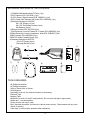
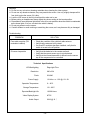
® ELECTRONICS CORP. VOH560PKG Drop Down Video Monitor and Video Cassette Player System Installation and Operation Manual Important Notice It is unlawful in most jurisdictions for a person to drive a motor vehicle which is equipped with a television viewer or screen that is located in the motor vehicle at any point forward of the back of the driver's seat, or that is visible directly or indirectly to the operator of the motor vehicle. Please note that the state of Rhode Island forbids the installation of such a device in a motor vehicle. MATERIALS INCLUDED IN THIS PACKAGE: 1)VOH560 Video Monitor with out TV Tuner (1 pc) 2)VCP Harness (P/N 112C3035) (1 pc) 3)12 Pin Power / Signal harness (P/N 112B2821) (1 pc) 4)2 Pin Power Wire Harness with choke (P/N 112B2824) (1 pc) 5)Hardware Package for VOH560 #4 x 3/8” Screws (12 pcs) #8 x 5/8” Self Drilling Screws (4 pcs) #8 Washers (4 pcs) 6)Remote Control (P/N 136C1957)(1pc) 7)Left Protective Cover for External A / V Inputs (P/N 102B3596) (1pc) 8)Right Protective Cover for Headphone Jacks (P/N 102B3597) (1pc) 9)Mini Console (P/N 102D3595) (1pc) 10)AVP756 Video Cassette Player (1pc) 11)Hardware Package for AVP756 #4 x 3/8" Screws (4 pcs) Mounting Bracket (2 pcs) ➀ ➁ ➂ ➄ ➅ 3c POWER VIDEO or GAME REPLAY + PICTURE SELECT WIRED HEADPHONE VOLUME CONTROL 3e REW PLAY ➃ CHOKE ➆ ➇ ➈ ➉ 11 VID EO 3c A U D IO L A U D IO R POWER S T O P /E J E C T RE W P LA Y FF R E P E AT TOOLS REQUIRED: #2 Phillips Screwdriver #1 Phillips Screwdriver Utility or Razor Knife or Shears Wire Strippers Upholstery hook tool (for removal of panels as necessary) Electrical Tape Masking Tape Multimeter (to verify 12 volt DC and continuity: Do not use a test light or logic probe) Marker pen – to mark headliner Scribe (to mark trim ring if used) Misc. electrical connectors (to connect to vehicle power source). Requirements will vary from vehicle to vehicle) Video tape (to verify system operation after installation) -1- FWD STOP GENERAL INSTALLATION APPROACH: 1) Decide upon system configuration and options that will be installed (i.e.: what components, VCP, RF Modulator/external amp, remote headphone, 2nd VCP, etc.). 2) Review all manuals to become familiar with electrical requirements and hook ups. 3) Decide upon mounting locations of all components and method of mounting. 4) Prep the vehicle by removing any interior trim necessary to gain access to vehicle's wiring as well as all areas where interconnecting wire harnesses will need to be located. If any access holes need to be cut into the vehicle (headliner, other trim components etc.), this should be done now as well. (Refer to Page 3). 5) Route the wiring harnesses through out the vehicle as necessary. (Refer to the Wiring Diagrams on page 6 of this manual as well as the wiring instructions for the individual components and accessory options being installed). Be sure that all wiring is protected from sharp edges and is routed in such a manner that it will not be pinched when all components and interior trim are fully installed. Be sure to leave enough slack in the wiring at each component to allow working room. 6) Remove all A/V system components from their packaging and place them loosely in the vehicle at their respective locations. 7) Connect all components together (electrically) and verify proper operation of all system functions. Note: This is best done BEFORE, components have been permanently mounted. 8) After verifying proper operation of the system, proceed to mount each component. 9) When all components are mounted, recheck function of entire system again to ensure that no wiring was pinched or connected improperly during final installation. GENERAL SYSTEM CONFIGURATION: The following is intended to give a rough guideline of system configuration that are possible with the VOH560PKG Drop Down Video System: System : Video Monitor without tuner (VOH560), VCP (AVP756). -All wiring necessary is included with this package. -Headphone is connected into the headphone jack on the monitor itself. Notes: -There are a few audio output options that can be added as follows: a) Additional speakers can be added to a VOH560 using the speaker outputs. Refer to the wiring diagram on page 6. -The VOH560 is only intended for an overhead, drop down installation. It is not intended for seat back or any other type of mounting. The hinging mechanism is designed for horizontal, drop down use only. -2- VEHICLE PREPARATION: 1) 2) 3) 4) Locate a constant power source (+12v at all times) and an accessory power source (+12v when key is in the acc. and run positions, and 0v when key is off). Generally, these wires can be found at the ignition switch or fusebox. The mounting method and location will vary from vehicle to vehicle, so this manual will only focus on the installation of the video monitor and related console accessories. Generally, the best location for the video monitor is where the vehicle's factory dome light is installed. The monitor should be located in such a manner that it can be comfortably viewed by rear seat passengers. NEVER INSTALL THE MONITOR IN A PLACE WITHIN THE DRIVER'S VIEW. THIS IS NOT ONLY DANGEROUS, BUT IT IS ALSO ILLEGAL IN MANY STATES Once the mounting location of the monitor has been determined, there may be additional preparation work necessary, depending on the vehicle structure and installation method. Some of the steps that may be required are: A) Removal of the vehicle's dome light B) The headliner may need to be trimmed as per the drawing below C) If the mini-console (P/N 102D3595) will be used, it will have to be trimmed to fit the contour of the vehicle's headliner. Refer to the "Mini-Console installation" section later in this manual. Note: If your installation will require you to cut out the headliner, the box that this kit came in can be used as a template. You can remove the shelf that the video monitor rests on and trace the opening onto the headliner for cutting FULL SIZE CONSOLE INSTALLATION There are several “full size” custom consoles available for selected vehicles. Some of these vehicles are the Chevrolet Suburban, Ford Expedition, and Dodge Durango. These full size consoles incorporate several additional features, and are particularly useful if the vehicle you are installing this system into already has an OEM overhead console in the headliner. Refer to the installation manual that comes with the console itself for complete installation instructions. -3- MINI CONSOLE INSTALLATION: This page only covers special installation considerations for the mini console installation. If the video monitor is to be installed with a custom full sized overhead console, refer to page 3. If the video monitor is to be installed in a vehicle with the mini console (P/N 102D3595), this console may need to be trimmed to fit the contour of the vehicle headliner. 1) 2) 3) 4) 5) In this installation, the video monitor is mounted directly to the overhead crossmember in the roof using the mounting screw bosses. These screw bosses should contact the crossmember directly (i.e.: no gap between the screw boss and the roof structure). Also, be sure that the screws do not pierce the outer roof skin when fully fastened to the crossmember. The mini console is attached to the video monitor using the perimeter screw bosses. It is important that the screws used in this installation are not overtightened, and that the video monitor and mini console are mounted in such a way that the assembly does not distort (or bend) when the mounting screws are tightened. An alternate method is to use a piece of plywood (5"x9"x3/4"). First secure the plywood block to the crossmember, then screw the monitor into the plywood. See the drawing on page 5. It is best to mount the video monitor to the roof structure without the mini console first. There should be a gap between the headliner and the outer flange of the video monitor. The mini console should be cut to full this gap. Apply masking tape to the outer surface of the mini console in the areas where the cut will be made. Mark the cut to follow the necessary contour of the roof. The suggested method of marking is as follows: A) First mark the narrowest point of the mini console on the masking tape. Be careful to consider not only vertical location, but fore-aft location. B) Using the handle of a screwdriver, make a “transfer marking tool” See diagram below. Place the tool against the roof, and the marker against the masking tape on the mini console. Trace the cut to be made around the entire perimeter of the mini console. C) Cut the mini console using a sharp utility knife or shears. Make the cut in several passes over the marked line, each time cutting a little deeper. It is not necessary to cut completely through the plastic, the cut only need be over 50% of the wall thickness of the plastic. By bending the cut back and forth several times, the plastic will break cleanly at the cut. D) Check the fit of the trimmed console and make any minor adjustments necessary. The mini console can be painted or covered with a material that matches the headliner before assembling the mini console to video monitor. The finished mini console should be attached to the video monitor, then attach the assembly to the roof. Headliner Headliner Cut line Cut Line Lowest Point Mark Lowest point mark Figure 6 Tape marker to screwdriver starting at your mark for the lowest point, then trace the contour of the roof Refer to Fig 7 for detail on attaching consoleat to your video pod and video pod to Tape marker to screwdriver. Starting mark vehicle structure. for the lowest point, trace the contour of the roof -4- MOUNTING THE MINI CONSOLE Roof Roof support Headliner 5"x9"x3/4" Plywood Block or Optional VOHBKT (4) #8x1" self drilling screws (not supplied) Mini-Console Video unit (4) #8 Flat washers (not supplied) (4) #8x3/4" self tapping screws (not supplied) -5- VOH560 N ote: cables ex iting the pod s hould be routed as sho w n. P o w e r H a rn e s s Item # 4 4 R e d: + 1 2 V D C (A c c es s o r y C ir.) M ini-D in C onnec tors c h o ke B la c k : Gro un d Option al Hard Wired FM M odulator Outpu t 12 V D C Pow e r an d Groun d TO FACTO RY RAD IO Am /Fm Antenn a Das h R a dio 2 R C A-F em ale Left Inpu t FM M odu lator 107 0610 1 LE FT W H I TE Pa tch C o rd R IG H T R ED R ig ht *R ef er t o Ins truc tions w ith the R F Inpu t M od ulato r K it fo r fu rthe r d etails. R C A-F em ale To Second ary AV M onitor TO OPTION AL AD DITIO NAL M OINTOR 12 V D C Pow e r an d Groun d Auxillary video d is pla y Ac ce ss ory H arnes s P/ N 801073 0 (Opt ional) R C A-F em ale IN PU T VID E O LIN E O UT VID E O Pa tch C o rd R C A M a le to M ale Ac ce ss ory H arnes s Item # 2 Optional R emote H eadphone Stations Ste re o H e a d ph o n e J ack G reen (Right+) Ste re o H e a d ph o n e J ack Blac k (G round) MONI TOR PORT OUT G ray (Left+ ) R ed R C A (Audio R ight) MONI TOR PORT OUT DC IN 12V W h ite R C A (Audio Left ) Po w er C o nnec tor 4 P in Ye llo w R C A (Vide o) (Opt ional D VD ) A/V OUTPUT VID EO WI RE REMOTE AUD IO L DC 12V R Item#11 1) Make the connections to the vehicle for the 12 pin wiring harness. 2) Remove screws on PCB Cover. Open the cover to gain access to Mini-Din Connector on main PCB. (Cover will remain attached at to rivet hole). 3) Insert the Circular Mini-Din Connector of the source Component Harness through the wire tie loop on the main PCB and into the Mini-Din Connector on the main PCB. 4) Pull the wire tie loop tight and cut off the excess. 5) Connect the Power Harness to the mating connector on the Video Monitor. 6) Connect the wired RF Modulator and / or the remote headphone jacks to the video monitor if those options are being included. 7) Connect power harness to vehicle’s electrical system by tapping into an accessory hot line. 8) Reinstall PCB cover using the 2 screws. 9) Verify all functions of the System before final mounting of the finished assembly. Note: A second VCP or other A/V Component can be connected to the video monitor system using a second Source Component Harness (purchased separately, part number: 8010730). This second harness would plug into the second Mini-Din connector on the main PCB as in steps 2 and 3 above. A/V Source Definitions: 1= VCP (right Mini Din on main PCB). 2= 2nd VCP (or game or future DVD, etc.…. left Mini Din). -6- CONNECTING THE DOME LIGHTS The dome lights in the video monitor require three connections to the vehicle's wiring. There are two common types of dome light circuits used, positive or negative switched. Positive systems supply voltage to the interior lights to turn them on, negative switched systems apply ground to illuminate the bulbs. To determine which system you have you must locate the wires at the dome light. On a positive switched system, with all the doors closed and the lights out, both wires at the dome light will rest at ground. When the light is activated, one of these wires will switch to +12 vdc. This is the vehicle's switching wire. On a negative switched system, with all the doors closed and the lights out, both wires at the dome light will rest at + 12vdc. When the light is activated, one of these wires will switch to ground. This is the switching wire. For positive systems, connect the purple / brown (Lamp auto) wire to the vehicle's switched wire. Then connect the red / black (lamp on) wire to a fused constant 12 volt source and the black / red (lamp common) wire to a good ground. Positive systems are commonly found on Ford vehicles. For negative systems, connect the purple / brown (Lamp auto) wire to the vehicle's switched wire. Then connect the red / black (lamp on) wire to a good ground and the black / red (lamp common) wire to fused constant 12 volt source. Negative systems are commonly found on General Motors and import vehicles. Note: Some vehicles which incorporate transistorized control of the dome light circuit, such as the 1999 Dodge Caravan, may require that the purple / brown (Lamp auto) wire be connected to the door pin switch wire, as the additional current draw of the Monitor's lights may not be supported by the output of the vehicles body control computer. Positive Switched Dome lighting To 12 pin connector on Monitor Red / black - Lamp on Black / red - Lamp common Purple / brown - Lamp Auto Factory Dome light circuit To constant +12vdc Factory Door ajar switch or Body Control computer -7- To constant +12vdc Negative Switched Dome lighting To 12 pin connector on Monitor Red / black - Lamp on Black / red - Lamp common Purple / brown - Lamp Auto To constant +12vdc Factory Dome light circuit To constant +12vdc Factory Door ajar switch or Body Control computer Troubleshooting: Symptom: Remedy: No power at Video Monitor -Verify +12 VDC on Red wire at 2 pin Power Harness behind video monitor. Verify ground connection with continuity test from known good ground to black wire at 2 pin Power Harness Power but no video or sound -Verify that the correct source is selected (i.e.: 1, 2 or 3). Verify that the source is on and playing a known good media (such as a videotape). Verify connections at both ends of the source component harness. Picture, but no sound -Push and hold the volume up button until sound is heard over headphones. If problem is limited to the dash radio, verify radio is tuned to the correct channel, and that power to the wired RF modulator is on. (Refer to instructions with modulator kit). Otherwise, verify all connections per the wiring diagram on page 6. No Infrared remote functions for VCP (or other components) -Check batteries in the hand held remote (not included with this kit). Verify that the IR LED ( page 6 Wiring Diagram) is property attached to the sensor window of the VCP (or other component). -8- 4 1 5 2 6 3A 7 8 9 10 3B Front Panel 1. Infrared Transmitter – Used to transmit audio to wireless headphones. 2. Power Button – (Bright red when system is On, dim when OFF). 3A. Forward Remote Sensor Eye – Allows the remote control to operate the VOH560 OSD (On Screen Display), control volume to wired headphone jacks (and optional external speakers), and to control the Video Cassette Player and other accessories. 3B. Side Remote Control Eye – Allows the remote control operate the VOH560 OSD (On Screen Display), control volume to wired headphone jacks (and optional external speakers), and to control the Video Cassette Player and other accessories. 4. Volume Up/Down – Controls volume to headphone jacks and external speakers if connected. 5. Picture Select – Select Contrast, Brightness, Color and Tint. 6. Source Select – Used to select one of A/V sources (AV 1, AV 2). 7. Three position Dome Light Switch • Auto – Automatically switches on the dome lights in conjunction with the vehicle’s interior illumination. • Off – The Dome Lights will not turn on in this position. • On – Turns on the Dome Lights. 8. Dome Lights – Provide additional interior illumination. 9. Screen Release – Slides in the direction of the arrow to release the drop down screen. 10. Headphones Jack – Allows plug-in of one wired headphone with 1/8” stereo plug. -9- VCP756 FRONT AND BACK VIEW V ID E O A U D IO L 8 A U D IO R 9 POWER 1 2 STOP/EJECT 3 REW PLAY 4 5 FF REPEAT 6 7 10 1. 2. 3. 4. Dust Cover – Protects VCP from dust and abuse access. Power Button – (Bright red when system is On, dim when Off). Stop / Eject Button – Used to stop the tape, and press it once more to eject the tape. (Fast) Rew Button : – Press Fast Rewind once in playback mode, the VCP enters the reverse picture search mode and the tape will rewind rapidly with the pictures. The rewind indicator lamp will blink. Press it once more, and the tape will rewind at a high speed with the lamp blinking more quickly. – Press Fast Rewind in the stop mode, the tape will rewind at a very high speed without any picture and sound. – Press Fast Rewind once in the (Fast) Forward mode, the VCP enters the reverse picture search mode and the tape will rewind rapidly with the pictures. The rewind indicator lamp will blink. Press it once more, the tape will rewind at a high speed. 5. Play Button – Press Play in the stop mode to playback a tape. You can also press it to release special operations such as the (Fast) Rewind mode and the (Fast) Forward mode. 6. (Fast) Forward Button : – Press Fast Forward once in the playback mode, the VCP enters the forward picture search mode and the tape advances rapidly with the pictures. The fast forward indicator lamp will blink. Press it once more, the tape will advance at a high speed with the lamp blinking more quickly. – Press Fast Forward in the stop mode, the tape will advance at a very high rate without any picture and sound. – Press Fast Forward once in the (Fast) Rewind mode, the VCP enters the forward picture search mode and the tape advances rapidly with the pictures. The fast forward indicator lamp will blink. Press it once more, and the tape will advance at a high speed. 7. Auto Repeat button – Press this button to activate this function. The tape is rewound automatically to the beginning after playing to the end. In this mode all controls, except for the Power button are disabled. Press it once more to deactivate this function. 8. Auxiliary A/V Stereo Input – Allows plug-in of camcorder, game, portable DVD player or other A/V source with RCA type output connectors. 9. Monitor Ports – Use one of the ports to connect to VOH560 mini din connector #1. Second port is reserved for connecting to another optional Clamshell Headrest Monitor. The port provides Video, Audio-R, Audio-L and 12volt DC to the monitor. 10. Not used. -10- REMOTE CONTROL OPERATION 1 5 BATTERY INSTALLATION Before attempting to operate your Remote Control, install the batteries as described below. POWER 3 VIDEO or GAME REPLAY + PICTURE SELECT 4 2 WIRED HEADPHONE VOLUME CONTROL 1) Turn the Remote Control face down. Press down on the ridged area of the battery cover and slide it off. 2) Install two “AAA” batteries as shown. Make sure that proper polarity (+ or -) is observed. 3) Slide the cover back until it clicks. 6 7 REW PLAY FWD STOP 8 9 The remote control will operate the VOH560PKG, It is not a universal remote control and will not control equipment from other manufacturers. Remote Controlled Monitor Functions 1. POWER ON/OFF Press this button to turn the VOH560 On. The channel number or current video source will be displayed on screen, and the picture will appear in a few seconds. Press the button again to turn the VOH560 Off. 2. VOLUME UP/DOWN BUTTONS Use these buttons to raise or lower the volume level of the headphone jacks or external speaker if installed. They are also used to make picture adjustments in picture select mode. Note: These buttons will not affect the volume of wireless headphones or a wired RF modulator. When using these devices the volume must be adjusted with the headphone volume control or with your radio’s volume control (see page 13, Headphones, or page 14, Wired FM Modulator). 3. PICTURE SELECT BUTTON Each time this button is pressed, the on screen picture adjustment display cycles through “adjustment bars” for CONTRAST, BRIGHTNESS, COLOR and TINT. Once the desired adjustment bar is displayed, use the VOLUME UP/DOWN buttons to adjust the setting. The display will automatically turn off if no adjustments are made within 6 seconds, or if any other button is depressed. 4. SOURCE SELECT BUTTON Any video equipment connected to the AUDIO / VIDEO inputs can be used with the monitor by pressing this button. Each time the button is pressed, the Audio / Video source will change in the following sequence VIDEO 1 and VIDEO 2. -11- Remote Controlled VCP Functions 5. REPLY BUTTON Pressing this button will rewind tape and immediately begin playback when the tape is fully rewound. 6. “REW” REWIND BUTTON If this button is pushed while the tape is stopped, the tape will rewind. If this button is pushed while the tape is playing, the VCP will go into rewind search mode. For more information, see page 10. 7. PLAY BUTTON Press this button to activate play mode while a tape is loaded into the VCP. This button may also be used to disengage search and pause modes. For more information, see page 10. 8. “F.FWD.” FAST FORWARD BUTTON If this button is pushed while the tape is stopped, tape will fast forward. If this button is pushed while the tape is playing, the VCP will go into fast forward search mode. For more information on the search feature of the VCP, see page 10. 9. STOP BUTTON Press this button to stop the tape. Turning the VOH560 On or Off 1. Slide the screen release lock forward to unlock the LCD screen and it will drop down slightly. Pivot the screen downward until a comfortable viewing angle is reached. The internal friction de tent will hold the screen in position while the system is in use. 2. Pressing the power button on the pod or the remote will turn the system on or off alternately. When in use the internal backlighting will illuminate the controls. 3. After the unit has been turned on and is displaying a picture, adjust the viewing angle, by pivoting the screen to optimize the picture quality. 4. Remember to turn the unit off and pivot the LCD to the locked position when not in use. Operation Overhead Dome Lights The lights integrated into the VOH560 are controlled by a three position slide switch. Sliding the switch to the on position will turn the lights on. The off position will prevent the lights from turning on and off with the vehicle’s interior lighting. Do not leave the vehicle unattended with the dome light switch in the on position, as this could result in a discharged battery. Dome Light Switch -12- Remote Sensor The VOH560 incorporates an infrared sensor which relays signals from the remote control to allow the VOH560 and VCP to be controlled simply by pointing its remote control at the remote sensor eye. This provides control of auxiliary equipment such as an Audiovox DVD. The infrared sensor can reply signals to auxiliary source that is connecting to monitor din connector #2, such as a DVD player. In this case you must use the remote control supplied with the DVD player. Remote Sensor Eye Remote Sensor Eye Optional Accessories Wired Headphones There is one 1/8” headphone jack on the VOH560 that can be used with any standard stereo headphones. This jack is controlled by the volume up / down buttons on the VOH560 or the remote control. Remove and save the protective plastic cover to access the jack. Remember to replace the cover when the jack is not in use. Wireless Headphones The VOH560 includes a built in infrared transmitter for use with Audiovox wireless headphones (PN MVSWHS). Turning the headphone switch on, and wearing them activates the internal micro switch which will activate the internal IR receiver and the volume can then be adjusted separately with the controls on each headset. Any number of wireless headphones can be used, but all must be within a line of sight from the transmitter, as infrared transmissions, like visible light travel only in a straight line. See the documentation accompanying your Audiovox wireless headphones. Infrared Transmitter Headphone Jack -13- Wired FM Modulator Your video system may be equipped with an RF modulator, that allows you to listen to the VOH560’s audio signal by tuning your vehicle’s radio to the selected frequency, (88.7 or 89.1 - check with your installer) and turning on the remote mounted RF modulator switch. (In most cases this toggle switch will be located underneath the driver’s side of the dash, check with your installer for the exact location.) Whenever the RF modulator is on, broadcast radio reception will be poor. Turning the remote mounted toggle switch off will allow normal radio reception. Optional Video Monitor(s) The VOH560 provides a video output for an optional video monitor(s). (Refer to page 6 of the installation guide for more details.) This output will provide a video signal that duplicates the signal displayed by the VOH560 to an additional monitor or video display. AVP756 provides monitor port for another optional monitor as well. Please see your installer for more information. Aux Video 2 When the video select button is pressed to access Video 2, Video 2 does not light up due to the video mute circuit unless there is a video source signal being applied into the second source. -14- Warnings ✦ Do not use any solvents or cleaning materials when cleaning the video system. ✦ Do not use any abrasive cleaners, they may scratch the screen. Use only a lightly dampened lint free cloth to wipe the screen if it is dirty. ✦ Lock the LCD screen in the fully closed position when not in use. ✦ Before putting on headphones always adjust the volume setting to the lowest position. ✦ Remember to leave the dome light switch in the off or auto positions when the vehicle is unattended, as the dome lights, if left on, can drain the vehicle’s battery. ✦ Do not put pressure on the screen. ✦ Caution children to avoid touching or scratching the screen, as it may become dirty or damaged. Troubleshooting PROBLEM SOLUTION Poor radio reception (FM modulator installed) • Check the condition of the vehicle’s radio antenna. • Verify that the antenna is fully raised. • If a wired RF modulator has been installed, verify that its switch is turned to the off position. IR sensor inoperative • Verify that the batteries in the remote are fresh. • Verify that the remote sensor eye is not obstructed. • Verify that the infrared transmitter is affixed over the sensor eye of the component to be controlled. Technical Specifications LCD Backlighting Edge Light Tube Resolution 960 x 234 Pixels 224,640 Power Supply 12 Volts + or - 10% @1.3-1.5A Operation Temperature 0 – 40°C Storage Temperature -20 – 80°C Expected Backlight Life 10,000 Hours Video Display System NTSC 0.6W @ 16 Ω Audio Output -15- F o r C ustom er S e rvice Visit O u r W eb site A t WWW.audiovox.com P ro duc t Inform a tio n, P h otos , FA Q ’s O w ner ’s M a nua ls © Copyright 2001 Audiovox Electronics Corp. 150 Marcus Blvd. Hauppauge, NY 11788 128-6065