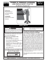
1
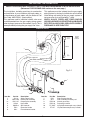
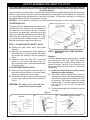
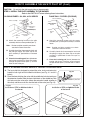
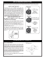
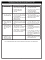
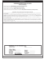
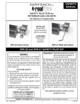
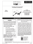
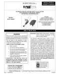
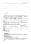
Robert H. Peterson Company
LOW PROFILE SAFETY PILOT KIT
Owner’s
Manual
For Natural or Propane Gas
INSTALLER:
Please leave these
instructions with the
consumer.
CONSUMER:
Please retain for future
reference.
MODEL #SPK-26
Important:
WARNING
If the information in this manual is not followed
exactly, a fire or explosion may result, causing
property damage, personal injury, or loss of life.
- Do not store or use gasoline or other
flammable vapors and liquids in the vicinity of
this or any other appliance.
WHAT TO DO IF YOU SMELL GAS:
• Open a window.
• Do not try to light any appliance.
• Do not touch any electrical switch; do not
use any phone in the building.
• Immediately call the gas supplier from a
neighbor’s phone. Follow the gas supplier’s
instructions.
• If you cannot reach the gas supplier, call
the fire department.
- Installation and service must be performed
by a qualified professional installer, service
agency, or the gas supplier.
INSTALLER & CONSUMER
These instructions MUST be
retained with this appliance.
Read these instructions carefully
before starting the installation of the
burner and control.
BE SURE THE FIREPLACE DAMPER IS FULLY
OPEN WHEN OPERATING THE BURNER
THE PETERSON BURNER IS TO BE BURNED
ONLY IN A FULLY VENTED, NONCOMBUSTIBLE
FIREPLACE WITH DAMPER AND CHIMNEY FREE
OF ANY OBSTRUCTIONS. THE FIREPLACE MUST
BE DESIGNED AND APPROVED TO BURN WOOD.
Like burning natural firewood, the Peterson burner is
designed to burn with a yellow, smoky flame. For this
reason, it must be adequately vented. Be sure the
fireplace damper is fully open when you burn the gas
burner. The smallest dimension of the chimney flue must
be at least 8". If it is smaller, DO NOT USE A PETERSON
BURNER. If fumes from the burner emerge into the room
when the damper is fully open, creating a smell like a
smoldering oil lamp, it indicates that the fireplace draft is
defective. Check chimney flue for obstructions. DO NOT
OPERATE LOGS UNTIL THE FIREPLACE DRAFT IS
CORRECTED. Check with the dealer or installer. Do not
use firewood with this unit.
This safety pilot system contains a control certified
by C.S.A.
Robert H. Peterson Co. • 14724 East Proctor Avenue • City of Industry, California 91746
REV 1 - 0711091249
1
No. L-A2-08107
IMPORTANT INFORMATION
CHECK TO BE SURE THAT THE SAFETY PILOT HAS BEEN ASSEMBLED FOR THE PROPER GAS.
(Reference FOR PROPANE GAS section on the next page.)
The installation, including provisions for combustion
and ventilation air, must conform with local codes, or,
in the absence of local codes, with the National Fuel
Gas Code, ANSI Z223.1 (latest edition).
This appliance must be isolated from the gas supply
piping system by closing its individual manual shutoff
valve during any testing of the gas supply system at
test pressures up to and including 1/2 psig.
This appliance and its individual shutoff valve must
be disconnected from the gas supply piping system
when testing at pressures that exceed 1/2 psig. This is
accomplished by closing the gas supply line valve.
WHEN GLASS FIREPLACE ENCLOSURES
(DOORS) ARE USED, OPERATE THE GAS BURNER
WITH THE GLASS DOORS OPEN; BOTH SIDES IF
FIREPLACE IS SEE-THRU TYPE.
PARTS LIST
To gas
supply
9
2
Supplied
with the
burner kit
CK-4
7
10
8
Pilot gas supply line
To
nipple
Thermocouple lead
3
Fig. 2-1
TO
LO
PI
5
0F
4
F
N
Gas inlet nipple
6
1
Item No.
1.
2.
or
3.
4.
5.
6.
Part No.
SV-19
PAC-1NAT
PAC-1LP
HS-32
KNOB-6
EH-2
SH-1
REV 1 - 0711091249
Description
Safety control valve
Natural pilot assembly
Propane pilot assembly
Heat shield
SPK-26 knob
Extension handle
Flame diverter bracket
Item No.
7.
8.
9.
or
10.
or
2
Part No.
PB-1
GP-1
PBO-20
PBO-10
PT-1NAT
PT-1LP
Description
Pilot mounting bracket
Pilot assembly insulation pad
Natural gas orifice
Propane gas orifice
Nat. pilot/thermocouple assy. w/leads
LP pilot/thermocouple assy. w/leads
No. L-A2-08107
HOW TO ASSEMBLE THE SAFETY PILOT KIT
This safety pilot kit must be installed by a qualified professional installer. Instructions must be
followed carefully when installing to ensure proper performance and full benefit from the gas burner
and safety pilot kit.
These instructions must be used as a supplement to the instructions supplied with the Peterson gas burner.
Follow the gas burner instructions and make adjustments as appropriate for the addition of a safety pilot
kit. Use gas pipe sealing compound that is resistant to all gasses, or Teflon tape, and apply to all male pipe
connections. Make sure that all connections are tight.
CAUTION: Do not cover the safety pilot valve with sand or lava granules, as it may cause overheating.
FOR PROPANE GAS
Note:
Heat shield is not
shown, but must be in
place when operating
the burner.
The safety pilot kit is shipped with a natural gas orifice
installed unless the safety pilot kit was received in
the same box as the propane burner. To change
from natural to propane gas, remove the pilot gas
supply line at the pilot end. Replace the natural gas
orifice with the propane gas orifice (Item 9, Fig.
2-1) contained in the envelope marked "L.P.-GAS".
Reattach the pilot gas supply line to the pilot.
SPK
valve
Fuel injector/
air mixer
STEP 1: CONNECTING THE SAFETY VALVE
Fig. 3-1
A. Remove the heat shield, knob, and handle
extension.
STEP 2: INSTALLING THE FLAME DIVERTER
BRACKET
B. Apply gas pipe compound or Teflon tape to the
fuel injector/air mixer pipe threads. Be careful
not to block the opening of the fuel injector/air
mixer.
Purpose:
The flame diverter bracket, when properly installed
onto Peterson G4, GX4, VG4, and P series burner
pans equipped with a safety control system, will
promote quicker ignition of the Peterson gas
burner and protect the safety control system from
overheating.
C. Screw the safety valve (Item No. 1) to the fuel
injector or air mixer on the burner (Fig. 3-1).
Be sure that the valve is positioned parallel with
the fireplace floor.
FOR LEFT-SIDED INSTALLATION:
A. Install the flame diverter bracket before
installing the pilot assembly.
A. Make sure the fuel injector and burner cap are
reversed so the fuel injector is on the left side of
the burner and the cap is on the right.
B. Place flame diverter bracket (Item 6) over the
side edge of the burner pan where the Peterson
safety control system pilot bracket (Item 7) will
be attached. The bracket should be placed
approximately 1 1/4" from the back of the burner
pan (see Fig. 3-2 or fig. 3-2C for left-sided
installation).
B. Flip the SPK-26 safety valve over so the opening
is to the right, and then mirror the illustration in
Fig. 3-1.
CAUTION: Be careful not to kink the pilot
supply tube or thermocouple.
C. Tap the bracket lightly with a hammer to secure
it in place.
Fig. 3-2
a.
b.
c.
Pilot assembly
1
Flame diverter
bracket
Left-sided installation example
Pilot
assembly
Pilot
assembly
1/
4"
Burner pipe
Mounting bracket
Insulation pad
Pilot bracket
Insulation pad
Burner pipe
Flame diverter
bracket
Flame diverter
bracket
Burner pan
Burner pan
REV 1 - 0711091249
3
No. L-A2-08107
HOW TO ASSEMBLE THE SAFETY PILOT KIT (Cont.)
CAUTION:
CAUTION:
Do not get granules into the pilot burner.
Do not kink the pilot supply tube or thermocouple.
STEP 3: INSTALL THE PILOT ASSEMBLY TO THE BURNER
Refer to the PARTS LIST when following these instructions.
GLOWING EMBER - G4, GX4, & VG4 SERIES
FLAME PAN - P SERIES (PROPANE)
Pilot assembly
Pilot assembly
Flame diverter
bracket
Mounting
bracket
Insulation pad
Mounting
bracket
Insulation
pad
Burner
pan
Flame diverter
bracket
Burner
pan
A. Attach the mounting bracket with the screws
provided (Item 7) to the pilot assembly as located
above.
A. Attach the mounting bracket to the pilot
assembly with the screws provided (Item 7).
Note:
Bracket and pilot assembly are shown
attached in above illustration.
Note:
B. Carefully bend the thermocouple lead and
the pilot gas supply line (Item 10) so the
pilot assembly is positioned as illustrated
above.
Bracket and pilot assembly are shown
attached in above illustration.
B. Carefully bend the thermocouple lead and
the pilot gas supply line (Item 10) so the pilot
assembly is positioned at end of the pan as
illustrated.
C. Place the insulating pad (Item 8) between
the bracket and the pan. Insert the screws
through the pilot bracket (Item 7) and the
holes in end of the pan.
C. Place the insulating pad (Item 8) between the
bracket and the pan. Insert the screws through
the pilot bracket (Item 7) and the holes in end of
pan.
STEP 4: ATTACHING THE HEAT SHIELD TO THE SAFETY CONTROL VALVE
A. The heat shield is designed to protect the valve, knob, and extension
handle in both right and left-sided installations (see Fig. 4-1 and 4-2
below).
MIDDLE KEY
SLOT
Middle
key HOLE
hole slot
L
0FF
PILOT
ON
B. Place the heat shield on the valve with the middle key hole slot resting on
the extension handle. Slide the heat shield back so the middle key hole
slot locks onto the valve collar (where the extension handle attaches to
the valve) and the rear slot fits over the back of the valve (see Fig. 4-3).
Fig. 4-3
Fig. 4-1
Fig. 4-2
Installation of SPK on right-hand-side
of the burner
Installation of SPK on left-hand-side of
the burner
L
L
TOLIP
ON
ON
REV 1 - 0711091249
4
PILOT
0FF
FF0
No. L-A2-08107
SPK-26 OPERATING INSTRUCTIONS
* We recommend that before you install the burner you familiarize yourself with the control valve layout. This will
help you to be confident operating the burner when fully installed (see figures below for typical control positions).
HOW TO LIGHT THE PILOT
Read here
To light the pilot from the PILOT position (Fig. 5-2),
push in slightly on the knob and turn to the OFF position
(Fig. 5-1). Wait five minutes, then turn the knob to the
PILOT position (Fig. 5-2). Push the knob fully in and at
the same time place a long lighted match or long necked
lighter at the pilot burner. The pilot should light. Hold the
knob in approximately 60 seconds. If the pilot does not stay
lit, turn to the full OFF position (Fig. 5-1). Wait five minutes
and repeat the LIGHTING INSTRUCTIONS.
HOW TO TURN THE GAS BURNER ON AND OFF
USING THE SAFETY PILOT KIT
1. Use OFF
only when complete
shutdown is necessary.
Fig. 5-1
OFF position
Burner off - pilot off
Read here
2. Turn dial to PILOT
position. With match ready,
press knob in and hold for 60
seconds while lighting pilot.
BE SURE THE DAMPER IS FULLY OPEN WHEN
OPERATING THE GAS BURNER.
TO TURN ON THE GAS BURNER FROM THE PILOT
POSITION: When the pilot is lit (Fig. 5-2), turn the knob
90° counter-clockwise to the ON position (Fig. 5-3).
TO TURN OFF THE GAS BURNER FROM THE ON
POSITION (Fig. 5-3): Turn the knob 90° clockwise to
the PILOT position (Fig. 5-2).
Fig. 5-2
PILOT position
Burner off pilot on
Read here
TO TURN OFF THE GAS BURNER AND THE PILOT
FROM THE PILOT POSITION (Fig. 5-2): Push in slightly
on the knob and turn 90° clockwise to the OFF position
(Fig. 5-1).
3. Turn knob to ON
to light burner.
Fig. 5-3
ON position
Burner on pilot on
Example
of burner
pilot flame
FOR IMPROVED PILOT OPERATION
PILOT ADJUSTMENT
Pilot adjustment
Should the pilot require adjustment, the following steps
should be taken: With the pilot lit and the control knob in
the pilot position, use a long narrow screw driver and turn
the pilot adjustment screw slowly clockwise to reduce the
pilot flame or counter-clockwise to increase the flame (Fig.
5-4). The adjustment screw can be turned so that the
pilot flame is completely extinguished. Some tightening of
the screw may occur during adjustment; this is normal. The
pilot flame should be a soft blue color with slightly yellow
tipping which encircles the thermocouple tip.
Turn the control knob to the ON position to assure proper
ignition of the log burner.
REV 1 - 0711091249
5
Fig. 5-4
No. L-A2-08107
TROUBLESHOOTING THE SPK-26 SAFETY PILOT KIT
PROBLEM
1. Pilot will not light
CAUSE
SOLUTION
a. Obstruction in pilot gas supply/
pilot gas supply line is kinked
a. Clear out obstruction. Replace pilot
gas supply line if kinked
b. Inadequate gas supply
c. Pilot out of adjustment
b. Have gas pressure checked by
installer or gas supplier
d. Air in line
c. Adjust pilot (see page 5)
d. Air should clear, attempt to relight
2. Pilot will not stay lit
after releasing knob
a. Pilot flame out of adjustment (tip
of the flame should encircle tip of
the thermocouple)
a. Adjust pilot (see page 5)
b. Thermocouple (SPK) either too
tight or too loose
c. Replace thermocouple
b. Thermocouple should be finger tight
and then 1/8" turn with a wrench
c. Bad thermocouple
3. Burner extinguishes
a few minutes after
lighting.
a. Inadequate gas supply causes
pilot flame to reduce after burner
lights
a. Using pilot adjustment, increase
gas to pilot. Pilot flame must be in
contact with the thermocouple tip
4. Burner extinguishes
after burning for some
time (approximately
10 minutes to 1
hour)
a. Thermocouple has overheated;
glass doors are closed
a. Be sure glass doors are open
during operation
b. Thermocouple has overheated;
insulation pad is not in place
b. Be sure that the insulation pad is in
place between the burner pan and
the pilot bracket
c. Thermocouple has overheated;
burner flames are heating the
thermocouple cold junction
5. Pilot will light without
holding in knob or
gas flows to burner
without pilot being lit
a. Valve is installed backward
c. Be sure the pilot assembly and
the flame diverter are in their
proper position. Rearrange logs so
that flame is not deflected to the
thermocouple
a. Reinstall valve with inlet por t
attached to gas supply and outlet
port attached to burner
If you still experience problems with the SPK-26 safety pilot kit, please contact a local Peterson dealer.
REV 1 - 0711091249
6
No. L-A2-08107
This page intentionally left blank.
7
WARRANTY
PETERSON VENTED GAS LOG SETS
LIMITED WARRANTY
All Peterson gas logs are WARRANTED for as long as you own them (lifetime).
All Peterson burner assemblies are WARRANTED for TEN (10) YEARS.
SPK-26 controls are covered by a THREE (3) YEAR “All Parts” Warranty.
All other Peterson valves, pilots, and controls are covered by a ONE (1) YEAR Limited Warranty (excluding batteries).
PLEASE KEEP A COPY OF YOUR SALES SLIP FOR PROOF OF PURCHASE
This warranty applies to the original purchaser and to single family residential use only. It commences from date of purchase, and is valid only with
proof of purchase.
This warranty does not cover parts becoming defective through misuse, accidental damage, electrical damage, improper handling, storage, and/or
installation. Product must be installed (and gas must be connected) as specified in the instructions or operator’s manual, by a qualified professional
installer. Accessories, parts, valves, remotes, etc., when used must be Peterson Co. product.
This warranty does not apply to rust, corrosion, oxidation, or discoloration, unless the affected component becomes inoperable. It does not cover
labor or labor-related charges.
This warranty specifically excludes liability for indirect, incidental, or consequential damages. Some states do not allow the exclusion or limitation of
incidental or consequential damages, so the above exclusion may not apply to you. This warranty gives you specified legal rights, and you may have
other rights that may vary from state to state.
For additional information regarding this warranty, or to place a warranty claim, contact the R.H. Peterson dealer where the product was purchased.
ROBERT H. PETERSON CO.
Quality Check
Date:___________
Orifice # (Main):__________
Orifice # (Other):__________
Leak Test:
___________
Burn Test:
___________
Gas Type:
NAT. / PROPANE
Model #:
___________
Serial #:
___________
Air Shutter: ___________
Inspector: ___________
Robert H. Peterson Co. • 14724 East Proctor Avenue • City of Industry, CA 91746
8