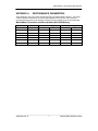
1
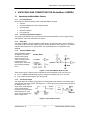
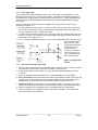
Manual No. 9400-0024 Revision G May 15, 2001 INSTRUCTIONS FOR OPERATING THE MotionMeter HIGH SPEED DIGITAL IMAGING CAMERA Redlake MASD, Inc. 11633 Sorrento Valley Road San Diego, California 92121-1097 Telephone: 1-800-854-7006 (USA and Canada only). Fax: (858) 481-6254 Outside the USA: (858) 481-8182 Internet: www.redlake.com REDLAKE MASD, INC. List of Manual Revisions Operator’s Instructions for the MotionMeter Model Camera – 9400-0024 Revision Date EO No. Notes A B 01-11-2000 02-18-2000 New Release Data Record becomes Event Marker. TM change. C 03-30-2000 Minor Changes/Corrections. D 05-10-2000 Update Menus, add Class A FCC declaration. E F 08-16-2000 12-14-2000 Delete references to color models. Other changes. G 05-15-2001 Change to Redlake MASD, Inc. Change Vcc to 3.3V. Delete 15X Exposure. Delete “Triggered” function. FCC Declaration of Conformity This equipment has been tested and found to comply with the limits for a Class A digital device, pursuant to Part 15 of the FCC rules. These limits are designed to provide reasonable protection against harmful interference when the equipment is operated in an industrial environment. This equipment generates, uses and can radiate radio frequency energy, and if not installed and used in accordance with the instruction manual, may cause harmful interference to radio communications. Operation of this equipment in a residential area is likely to cause interference in which case the user will be required to correct the interference at user’s expense. _____________________________________________________________________________ 9400-0024 Rev G ii 05/15/01 MotionMeter High Speed Video Camera PREFACE This manual describes how to operate and maintain a Redlake MASD, Inc. MotionMeter High Speed Digital Imaging monochrome Camera. The MotionMeter is used as a hand-held or tripodmounted unit. The camera records sequences of images from 60 to 1000 frames per second, depending on the model and setting. Images from the camera or from the Image Memory are displayed on the MotionMeter viewfinder and external monitor. Each sequence of images can be stored in a computer file. You can retrieve and replay the sequence at various speeds to analyze the event in detail. This manual contains the following sections: Section 1 Introduction to High Speed Motion Analysis. This section gives a tutorial for recording an event using the MotionMeter camera, and analyzing the recorded images. Section 2 Description of the MotionMeter Camera. This describes the operation and indications in the camera menus. Section 3 Unpacking and Connecting the MotionMeter Camera. This section describes how to unpack and set up the camera, connect the power and signal inputs and outputs. It also includes a power-on check. Section 4 Recording and Viewing Images on the MotionMeter Camera, describes how to set up the camera to record a video sequence. It describes how to view and analyze the images, and store the sequence in a computer file. Section 5 Maintaining and Troubleshooting the MotionMeter Camera. This section identifies problems that may occur during installation and operation, and suggests a solution. Appendices The Appendices show the frame storage and elapsed recording times, shutter speeds, performance specifications and the standard accessory kit. Copyright 2001 Redlake MASD, Inc. The information in this manual is for information purposes only and is subject to change without notice. Redlake MASD, Inc. makes no warranty of any kind with regards to the information contained in this manual, including but not limited to implied warranties of merchantability and fitness for a particular purpose. Redlake MASD, Inc. shall not be liable for errors contained herein nor for incidental or consequential damages from the furnishing of this information. No part of this manual may be copied, reproduced, recorded, transmitted or translated without the express written permission of Redlake MASD, Inc. _____________________________________________________________________________ 9400-0024 Rev. G iii OPERATOR'S INSTRUCTIONS REDLAKE MASD, INC. This page intentionally left blank. _____________________________________________________________________________ 9400-0024 Rev G iv 05/15/01 MotionMeter High Speed Video Camera TABLE OF CONTENTS 1 .. INTRODUCTION TO HIGH SPEED MOTION ANALYSIS .................................................... 1-1 1.1 Capturing the Video Image............................................................................................ 1-1 1.1.1 The Shutter............................................................................................................. 1-1 1.1.2 The Strobe Output .................................................................................................. 1-1 1.1.3 Composite Video Out ............................................................................................. 1-1 1.1.4 Lighting the Subject................................................................................................ 1-1 1.2 The Imager Responsivity Curves .................................................................................. 1-2 1.2.1 The Imager Base Characteristics ........................................................................... 1-2 1.2.2 Spectral Response with a CM500 IR Filter............................................................. 1-2 1.2.3 The Effect of the IR Filter........................................................................................ 1-2 1.2.4 Spectral Response without the CM500 IR Filter..................................................... 1-4 1.2.5 The Monochrome (Gamma) Curve ........................................................................ 1-4 1.3 Capturing an Image ....................................................................................................... 1-4 1.3.1 Recording a Video Sequence................................................................................. 1-4 1.3.2 Stopping a Recording using the Stop Buttons........................................................ 1-5 1.3.3 Stopping a Recording using a Trigger Input ........................................................... 1-5 1.3.4 Synchronization and Controlling the Record Speed............................................... 1-5 1.3.4.1 Synchronizing two or more MotionMeter cameras.......................................... 1-6 1.3.4.2 Controlling the Record Rate of a Camera from an External Source ............... 1-6 1.4 Marking a Frame (Event Marker)................................................................................... 1-6 1.5 The Image Memory ....................................................................................................... 1-6 1.6 Recording a Sequence in the Image Memory ............................................................... 1-6 1.6.1 Stop Recording....................................................................................................... 1-6 1.6.2 Stop Recording using the Trigger........................................................................... 1-7 1.6.3 Playing Images from the Image Memory................................................................ 1-7 1.6.4 Frame Numbers and Elapsed Time Display........................................................... 1-7 1.6.5 Saving a Sequence in a Computer File.................................................................. 1-7 1.7 Viewing the Image Sequence........................................................................................ 1-8 1.7.1 Loss of Frames During Playback ........................................................................... 1-8 1.7.2 Analyzing the Motion of a Subject .......................................................................... 1-8 2 .. DESCRIPTION OF THE MotionMeter CAMERA.................................................................. 2-1 2.1 MotionMeter Model and Part Numbers.......................................................................... 2-1 2.2 The MotionMeter Camera.............................................................................................. 2-1 2.2.1 2.3 MotionMeter Features and Functions..................................................................... 2-1 MotionMeter Controls and Indicators ............................................................................ 2-2 2.3.1 The RECORD Button ............................................................................................. 2-2 2.3.2 The PLAY Buttons .................................................................................................. 2-2 2.3.3 The STOP Button ................................................................................................... 2-2 2.3.4 The MENU Button .................................................................................................. 2-3 2.3.5 The SELect Button. ................................................................................................ 2-3 _____________________________________________________________________________ 9400-0024 Rev. G v OPERATOR'S INSTRUCTIONS REDLAKE MASD, INC. 2.3.6 2.4 The + and - Buttons................................................................................................ 2-3 The Menus..................................................................................................................... 2-3 2.4.1 LIVE Mode.............................................................................................................. 2-3 2.4.1.1 Record Rates .................................................................................................. 2-3 2.4.1.2 Shutter Speed ................................................................................................. 2-3 2.4.1.3 Trigger Point.................................................................................................... 2-3 2.4.2 Record Mode.......................................................................................................... 2-4 2.4.3 Playback Mode....................................................................................................... 2-4 2.4.4 The Settings Menu ................................................................................................. 2-5 2.5 Input and Output Connectors ........................................................................................ 2-5 2.5.1 Power ..................................................................................................................... 2-5 2.5.2 Digital in.................................................................................................................. 2-5 2.5.3 Digital Out............................................................................................................... 2-5 2.5.4 Trigger .................................................................................................................... 2-5 2.5.5 Video Out ............................................................................................................... 2-5 2.6 Power Sources to the Camera ...................................................................................... 2-6 2.6.1 Power Outlet........................................................................................................... 2-6 2.6.2 Battery Pack and Charger ...................................................................................... 2-6 2.6.3 Automobile Supply ................................................................................................. 2-6 3 .. UNPACKING AND CONNECTING THE MotionMeter CAMERA......................................... 3-1 3.1 Unpacking the MotionMeter Camera............................................................................. 3-1 3.1.1 List of Equipment.................................................................................................... 3-1 3.1.2 Connecting the External Options ........................................................................... 3-1 3.1.3 Video Out ............................................................................................................... 3-1 3.1.4 The Event Marker Input.......................................................................................... 3-1 3.1.5 The Strobe Output .................................................................................................. 3-1 3.1.6 The Trigger Input .................................................................................................... 3-3 3.1.7 The Phase-Lock Input and Output ......................................................................... 3-3 3.1.7.1 Connecting MotionMeter Cameras to an Equipment Source.......................... 3-4 4 .. RECORDING AND VIEWING IMAGES ................................................................................. 4-1 4.1 Recording an Event Sequence...................................................................................... 4-1 4.1.1 4.2 Setting up the Camera to Record .................................................................................. 4-1 4.2.1 4.3 Camera Defaults .................................................................................................... 4-1 Set the Record Values............................................................................................ 4-1 4.2.1.1 Event. .............................................................................................................. 4-1 4.2.1.2 Record Rate. ................................................................................................... 4-1 4.2.1.3 Shutter............................................................................................................. 4-1 4.2.1.4 Trigger. ............................................................................................................ 4-1 4.2.1.5 Event Marker Input.......................................................................................... 4-1 Recording an Event Sequence...................................................................................... 4-1 4.3.1.1 4.4 Press the Record button. ................................................................................ 4-2 Frame on Demand......................................................................................................... 4-2 _____________________________________________________________________________ 9400-0024 Rev G vi 05/15/01 MotionMeter High Speed Video Camera 4.5 Synchronizing Two or More Cameras .......................................................................... 4-2 4.6 Viewing the Stored Images............................................................................................ 4-2 5 .. MAINTENANCE AND TROUBLESHOOTING....................................................................... 5-1 5.1 Routine Maintenance..................................................................................................... 5-1 5.2 Troubleshooting............................................................................................................. 5-1 5.2.1 No Picture on the Viewfinder or Monitor................................................................. 5-1 5.2.2 Video Channel Imbalance ...................................................................................... 5-1 APPENDIX A PERFORMANCE PARAMETERS.......................................................................I APPENDIX B PERFORMANCE SPECIFICATIONS.................................................................II APPENDIX C EXPOSURE AT EACH SHUTTER SPEED ...................................................... IV APPENDIX D ACCESSORIES ................................................................................................. V LIST OF FIGURES Figure 1-1 The Spectral Characteristics of the TC237 Sensor. ................................................... 1-2 Figure 1-2 The Response of the RGB Signal with an IR Filter. ................................................... 1-2 Figure 1-3 Filter Blocking Characteristics. ................................................................................... 1-3 Figure 1-4 Sensor RGB Spectral Response without an IR Filter. ................................................ 1-4 Figure 1-5 The Monochrome Curve............................................................................................. 1-4 Figure 1-6 The Phase Lock Connections. ................................................................................... 1-5 Figure 1-7 The Image Memory. ................................................................................................. 1-6 Figure 1-8 The 50% Trigger......................................................................................................... 1-7 Figure 1-9 The 0% Trigger......................................................................................................... 1-7 Figure 2-1 The MotionMeter Controls. ......................................................................................... 2-2 Figure 2-2 The Live Mode Screen. .............................................................................................. 2-3 Figure 2-3 The Record Mode Screen. ......................................................................................... 2-4 Figure 2-4 The Playback Mode Screen. ...................................................................................... 2-4 Figure 2-5 The Settings Menu. .................................................................................................... 2-5 Figure 3-1 The Event Marker Input Circuits. ................................................................................ 3-1 Figure 3-2 The Strobe Circuits..................................................................................................... 3-1 Figure 3-3 Trigger Input Circuits. ................................................................................................. 3-3 Figure 3-4 The Phase Lock Signal and Circuit. ........................................................................... 3-4 Figure 5-1 Video Channel Imbalance. ......................................................................................... 5-1 LIST OF TABLES Table 1-1 Light Value Requirements for the MotionMeter Camera. ............................................ 1-1 Table 2-1 The MotionMeter Model and Part Numbers................................................................. 2-1 _____________________________________________________________________________ 9400-0024 Rev. G vii OPERATOR'S INSTRUCTIONS REDLAKE MASD, INC. This page intentionally left blank. _____________________________________________________________________________ 9400-0024 Rev G viii 05/15/01 MotionMeter High Speed Video Camera 1 INTRODUCTION TO HIGH SPEED MOTION ANALYSIS The MotionMeter is a hand-held High Speed Digital Imaging Camera that records a sequence of images of an event at a frame rate of 60 to 1000 frames per second, depending on the model of video camera used. The camera stores these images in a digital Image Memory. These images can be viewed forward or reverse at selected frame rates from 1 to 1000 frames per second (fps), or freeze frame, to analyze motion and time during the event. The camera provides video for external viewing or storing the images on a computer or VCR. 1.1 Capturing the Video Image The camera lens focuses the subject onto a CCD imager. The camera accepts any C-mount lens, fixed or zoom, with a wide angle, normal view or telephoto. The telephoto lens may be used in its normal range or in macro to capture a very small subject. The exposure of each frame is reduced at the higher frame rates, so more illumination is required as the frame rate increases. The correct exposure may be achieved by opening the aperture. If you still need more light, you must provide additional incandescent light. The MotionMeter also provides a Strobe output to control a strobe light for additional illumination. 1.1.1 The Shutter The camera provides shutter control of image exposures that allows you to reduce the time of each frame exposure to eliminate image blurring due to motion. You must increase illumination to compensate for the shorter exposure. The Strobe output is synchronized to the shutter timing so a strobe may be used to increase illumination as well as to eliminate motion blur. Refer to Appendix C for shutter exposure information. 1.1.2 The Strobe Output The Strobe output is available from the Digital Out connector during Live or Record mode, when selected from the Settings menu. This is a TTL output pulse synchronized to the shutter, so that the strobe output signal goes high when the shutter is open and low when the shutter closes. 1.1.3 Composite Video Out The camera supplies an NTSC RS170 or PAL signal output, selected on the Settings menu. The video sequence can be viewed on an external monitor, or recorded on a host computer or a VCR. You can save the video pictures for later retrieval and study. 1.1.4 Lighting the Subject The Camera Imager must receive enough light to see details of the image, and record the subject at the optimum size, so the significant parts of the motion can be seen clearly. The standard monochrome camera has an infrared filter to give subjects the correct gray scale appearance. Table 1-1 Light Value Requirements for the MotionMeter Camera. Standard Camera Low-Light Camera Option Frame Rate (fps) LUX Value Foot Candles LUX Value Foot Candles 50, 60 1.03 0.10 0.10 0.01 250 4.3 0.41 0.43 0.04 500 8.6 0.83 0.86 0.08 1000 17.2 1.65 1.72 0.17 The Low Light Camera Option does not have the IR filter, which increases the sensitivity of the camera at low light levels. Table 1-1 gives minimum incandescent (tungsten) light requirements for the standard and low light cameras at a 1X shutter setting. Refer to Appendix C to determine the light values at other shutter settings. _____________________________________________________________________________ 9400-0024 Rev. G 1-1 OPERATOR'S INSTRUCTIONS REDLAKE MASD, INC. 1.2 The Imager Responsivity Curves The camera has a TC237 monochrome CCD imager. The imaging sensor has an image area of 658 (H) x 496 (V) pixels, each pixel being 7.4 microns square. The imager has a built-in electronic shutter to limit the exposure, see Appendix C. All standard cameras have the CM500 1mm IR filter. The filter is omitted on the low light version of the camera. Imagers. Filters are installed at the factory and cannot be changed in the field. 1.2.1 The Imager Base Characteristics Figure 1-1 gives the responsivity and sensitivity of the TC237 monochrome CCD imager without a filter across the range of visible light to the near IR band. Figure 1-1 The Spectral Characteristics of the TC237 Sensor. 1.2.2 Spectral Response with a CM500 IR Filter Figure 1-2 shows the response of the red, green and blue signals from the TC236 imager with the IR filter installed. Blue Green Red Figure 1-2 The Response of the RGB Signal with an IR Filter. 1.2.3 The Effect of the IR Filter. Figure 1-3 shows the blocking effect of the 1-mm CM500 IR filter. Figure 1-3 Filter Blocking Characteristics. _____________________________________________________________________________ 9400-0024 Rev G 1-2 05/15/01 MotionMeter High Speed Video Camera 1.2.4 Spectral Response without the CM500 IR Filter This set of curves shows the spectral response for the red, green, and blue signals without an IR filter. See Figure 1-4. Blue Green Red Figure 1-4 Sensor RGB Spectral Response without an IR Filter. 1.2.5 The Monochrome (Gamma) Curve The Monochrome Curve shows the imager 8-bit gray scale with values from 0 to 255. See Figure 1-5. If the Gamma feature is turned off on the Settings menu, the response is linear over the range, with a slope of 1. Figure 1-5 The Monochrome Curve. 1.3 Capturing an Image The MotionMeter serves two types of application: recording a specific event, or viewing a continuous video until an event triggers an end to the sequence. The elapsed recording time depends on the number of frames per second recorded and the number of frames that the memory can store. Refer to Appendix A where the elapsed record time can be determined from the Record Rate and the capacity of the Image Memory. 1.3.1 Recording a Video Sequence During recording, the camera stores frames in the image memory. The images wrap around the memory overwriting the oldest frame until an operator presses the Stop button, or a trigger generated by an external source stops the recording process. 1.3.2 Stopping a Recording using the Stop Buttons The Stop command stops the sequence and the frames show the images preceding the last frame. There is a delay through the camera so the sequence shows a few frames after the camera received the Stop command. _____________________________________________________________________________ 9400-0024 Rev. G 1-3 OPERATOR'S INSTRUCTIONS REDLAKE MASD, INC. 1.3.3 Stopping a Recording using a Trigger Input The MotionMeter trigger input circuit detects a signal from an external source and stops the recording at the frame active at the receipt of the trigger. This enables you to record an event that either occurs very quickly, or happens without warning and when the camera operates unattended. You should always use the trigger if you want to have the event coincide with the Frame 0, since the Stop button has a propagation delay. You can set the Trigger Point to determine how many frames you record before the event. The active frame when the trigger is received is designated Frame 0. Frames following Frame 0 have positive numbers, and the frames that precede Frame 0 have negative numbers. Refer to Section 1.6 for more information. The Trigger input is always enabled and held at +3.3 volts through a 10K ohm resistor. You supply the trigger signal to the trigger input in one of the following ways. The camera must be set to receive a rising or falling signal, selected in the Settings menu. 1. An open circuit allows the trigger input to stay at +3.3 volts. The trigger causes a contact closure that pulls the trigger input down to 0 volts. 2. A closed contact pulls the trigger input down to 0 volts. The trigger opens the contact causing the trigger input to rise to +3.3 volts. 3. The trigger input operates with TTL or CMOS logic as the trigger source. The voltage from the source is pulled low by a resistor at the source up to 2K ohms in value. The trigger causes the signal to go to +3.3 volts to stop recording, and the signal to the trigger input can go as high as +30 volts. 1.3.4 Synchronization and Controlling the Record Speed The Phase Lock feature provides a means to synchronize and control the frame rate of the recorded video. This provides three functions: • Record a single frame (Frame on demand). • Synchronize two or more cameras together. • Slave a camera to an external source such as rotating equipment or a signal generator. The frame rate during record will follow the source signal and can be at any rate up to the Record Rate set. The Phase Lock In and Out signals are connected to the Digital In and Out connectors. Select the Phase Lock function in the Settings menu. If the rate of recording varies from a record rate of 60, 125, 250, 500, or 1000 frames per second, the camera records the events and assigns an accurate frame number to each frame. However, the elapsed times (ET) displayed on the menu will not be the true elapsed time. Figure 1-6 The Phase Lock Connections. _____________________________________________________________________________ 9400-0024 Rev G 1-4 05/15/01 MotionMeter High Speed Video Camera 1.3.4.1 Synchronizing two or more MotionMeter cameras The cameras should be connected as shown in Figure 1-6. One camera is designated the Master and the other camera(s) are designated as Slave(s) in the Settings menu. Cameras are usually connected in series. The most common series connection requires a BNC cable to connect the Phase Lock Out from the Master or leading unit to the Phase Lock In connector on the next downstream unit. Alternatively, the signal can be distributed to each camera using a tee connector. All master and slave cameras must be set to the same Record Rate for accurate elapsed time (ET) indications. 1.3.4.2 Controlling the Record Rate of a Camera from an External Source The camera records one frame each time a phase lock signal is detected at the Phase Lock In connector. A stream of signals can be supplied at any speed to record a series of frames up to the maximum Record Rate set. The Phase Lock In input is normally tied to +3.3 volts through a 10K ohm resistor. The input signal to record a frame is a square-wave signal rising from 0 volts to +3.3 volts. The input signal must pull the Phase Lock In input to ground, then provide the rising signal to record the frame. The elapsed time (ET) indications for the slave units are not true when the frame rate does not equal the record rate set. Refer to Section 2.6.5 for more details. 1.4 Marking a Frame (Event Marker) The MotionMeter provides a means to identify a frame or series of frames in the recorded sequence. This Event Marker feature, when turned on, places a square marker at the top left corner of each frame. The Event Marker inputs are held high (+3.3V TTL level) and the marker shows as a black square on each frame. A contact closure to ground pulls the input low and the marker shows as a white square. The input must be enabled using the Settings menu. The Event Marker input is through the Digital In BNC connector. The event marker is not available in the Slave mode. 1.5 The Image Memory There are two sizes of SDRAM available, 64K (standard memory) and 128K (enhanced memory). See Appendix A for the recording times and number of frames over the range of record rates. The MotionMeter memory can only be upgraded at the factory or at an authorized service center. 1.6 Recording a Sequence in the Image Memory When the camera records, the first image is stored in Initial Frame 0, see Figure 1-7. The camera places the next images in Frames 1, 2 up to the last frame in the image memory, then records over Frame 0. The camera records the latest video over the oldest frame so that the total number of frames available is equal to the number of frames in the image memory. 1.6.1 Stop Recording When you press the Stop button, the camera stops recording and returns to the Live mode. You may enter an instruction to record again, playback from the image memory, save the sequence or return to Live mode. All images in the memory precede the active frame when you pressed the Stop Button. The first frame of the next recorded sequence follows the last frame of the previous sequence. Figure 1-7 The Image Memory. _____________________________________________________________________________ 9400-0024 Rev. G 1-5 OPERATOR'S INSTRUCTIONS REDLAKE MASD, INC. 1.6.2 Stop Recording using the Trigger The camera also stops recording when it receives a signal through the Trigger input. Recording stops at the frame determined by the Trigger Point setting, see Figure1-8. The trigger can be set from 0% to 100% in 10% increments to adjust the length of time the images show before and after the event that caused the trigger. The percent value represents the proportion of the sequence shown before the event. For example, if the trigger is set to 50% as illustrated, the camera continues to record over the second half of the image memory and then stops. Half of the sequence shows frames that precede the trigger and half shows events after the trigger. If the Trigger Point is set to 20%, then 20% of the images precede the trigger, and 80% follow the trigger. Figure 1-8 The 50% Trigger. The active frame when the trigger is received is Frame 0 for that sequence. If the Trigger point were set to 0%, all images in the memory would show events after the trigger occurred. If the Trigger Point were set to 100% all images would precede the trigger, the equivalent of using the manual stop. A message shows on the screen between the time of receipt of the trigger signal and the time the camera stops recording to confirm that the trigger was received and to prevent the operator from pressing Stop manually. Figure 1-9 The 0% Trigger. 1.6.3 Playing Images from the Image Memory You can play back the images from memory as soon as the sequence is recorded. The camera plays the images in Step mode, or at playback rates from 1 fps to 1000 fps. The images can be saved in a computer file and replayed at any time. 1.6.4 Frame Numbers and Elapsed Time Display During playback from the image memory or from a computer file, the menu shows the frame number and time of the frame currently displayed. These numbers are referenced from the Frame 0 assigned to that sequence. Frames following Frame 0 trigger are assigned positive frame numbers from Frame 1 to the last frame stored. Frames preceding the trigger are given negative frame numbers from Frame –1 to the first frame stored. The viewfinder and monitor shows the time of each frame to 0.0001 seconds with reference to Frame 0. 1.6.5 Saving a Sequence in a Computer File. Images recorded in the image memory will be lost if another recording is made. Therefore any video data required later must be stored externally before making another recorded sequence. Connect the Video Out output to a VCR or a computer with a video processor board. _____________________________________________________________________________ 9400-0024 Rev G 1-6 05/15/01 MotionMeter High Speed Video Camera 1.7 Viewing the Image Sequence The video images from the camera in Live mode, or from the Image Memory, are shown in the viewfinder. To see the video sequence in detail, the pictures must be seen on a remote monitor connected to the video output through the Composite Out cable connector. The MotionMeter camera provides either NTSC or PAL video, selected by the Settings menu. 1.7.1 Loss of Frames During Playback Playback at frame rates above 60 fps (50 fps PAL) will cause the loss of frames displayed in the viewfinder and on computer displays. This does not indicate a loss of video data. All frames can be accessed at lower playback rates. 1.7.2 Analyzing the Motion of a Subject The MotionMeter provides several features to examine a recorded sequence. 1. Slow or Fast Motion. You can replay the video sequence at speeds of 1 fps to 1000 fps, forward and reverse. 2. Viewing Frame by Frame. You can step through the sequence one frame at a time, forward and back. 3. Fast Forward and Reverse. Hold a Play button down to fast forward or reverse through the sequence. 4. Frame and Time References. The Playback menu shows the frame number currently displayed and the time from Frame 0. _____________________________________________________________________________ 9400-0024 Rev. G 1-7 OPERATOR'S INSTRUCTIONS REDLAKE MASD, INC. This page intentionally left blank. _____________________________________________________________________________ 9400-0024 Rev G 1-8 05/15/01 MotionMeter High Speed Video Camera 2 DESCRIPTION OF THE MotionMeter CAMERA The MotionMeter is a Camera that records a video event in an internal digital memory, and replays the event at playback speeds from freeze frame, and 1 frame per second (fps) to 1000 fps in a 3.5” viewfinder on the rear panel. You can view the video images on an external monitor, or download and store each event on a VCR or a computer equipped with a video processor card. The event can be retrieved and played back later for further analysis. There are six MotionMeter models available, refer to Table 2-1 below. Refer to Appendix A for the MotionMeter Performance Specifications giving record times for memory capacity and record rates. Refer to Appendix D for the Accessory Kit that specifies the lenses available, mounting hardware and lighting equipment. 2.1 MotionMeter Model and Part Numbers These tables give the model numbers of MotionMeter cameras covered by this manual. Table 2-1 The MotionMeter Model and Part Numbers. Model No. Part No. Record Rate Range (Frames per Second) MotionMeter 250 1140-0001 (50 PAL), 60, 125, 250 MotionMeter 500 1140-0002 (50 PAL), 60, 125, 250, 500 MotionMeter 1000 1140-0003 (50 PAL), 60, 125, 250, 500, 1000 2.2 The MotionMeter Camera The camera has an enclosure that is 8.3” (211 mm) wide, 5.5” (140 mm) high and 2.5” (64 mm) deep. The enclosure has a 3/8-16 threaded hole in the bottom of the enclosure to mount the Camera Head onto a tripod. All standard cameras have IR filters that give the subject an accurate grayscale rendering. A model of camera without a filter is available for low light applications. Refer to Paragraph 1.1.1 for the light value requirements for each of these models. 2.2.1 MotionMeter Features and Functions The camera provides the following features and functions: 1. C-mount lens. 2. The camera has a 1/3-inch format video imager. 3. The Camera provides a composite NTSC or PAL video output signal (software selectable). 4. The SDRAM memory chips have a capacity of 64Kbytes (standard memory) or 128Kbytes (enhanced memory). 5. Record rates are (50 PAL, 60 NTSC), 125, 250, 500, and 1000 fps. The image goes to half height (110 pixels placed in the middle of the screen) at 1000 fps. 6. Exposure rates include 1X, 2X, 3X, 4X, 5X, 10X, and 20X. 7. A 3 ½” LCD viewfinder shows the video images live from the camera during Live mode. During Record, the viewfinder and external monitor shows the sequence as it is recorded. During Playback, the viewfinder and monitor show the image from the image memory. 8. Play the sequence at various speeds from Step mode to 1,000 fps to analyze the data. 9. Phase Lock In to record frames on demand, to synchronize two or more cameras, or to synchronize one or more cameras to external equipment. 10. Event Marker marks frames for identification during record. 11. Strobe Out synchronizes frames with a strobe light during record. Note that the input and output function, items 9-11, are selected through the Digital In and Digital Out connectors; refer to paragraph 2.4.4. _____________________________________________________________________________ 9400-0024 Rev. G 2-1 OPERATOR'S INSTRUCTIONS REDLAKE MASD, INC. 2.3 MotionMeter Controls and Indicators All controls and the display are located on the back of the Unit. Symbols are used to show the functions except for the MENU and Select (SEL) buttons. Figure 2-1 The MotionMeter Controls. 2.3.1 The RECORD Button A momentary push button that turns the Record function ON. The screen shows the REC mode. All buttons except Stop are disabled during Record. The camera returns to Live mode when the Stop button is pressed. 2.3.2 The PLAY Buttons Press a PLAY button momentarily to view a sequence of images from the Image Memory at the frame speed set, forward or reverse. The screen shows PLAY mode. Press the + or - buttons to increase or decrease the number of frames displayed per second during playback by one step in the range. In STEP mode, each push of the PLAY button advances or reverses one frame. Press the PLAY button for a longer period to fast forward or rewind through the frames in the image memory. The camera returns to LIVE when the STOP button is pressed. 2.3.3 The STOP Button This button terminates the Record or Play function and returns the camera to the LIVE mode. _____________________________________________________________________________ 9400-0024 Rev G 2-2 05/15/01 MotionMeter High Speed Video Camera 2.3.4 The MENU Button This momentary push button selects one of three states: 1. LIVE mode. 2. The SETTINGS menu. See the Settings Menu description below. 3. Menu OFF. This turns the Menu displays OFF and allows you to view the full video. If the Menu is OFF, press the MENU button to display the LIVE mode menu. 2.3.5 The SELect Button. This button selects the next parameter in the menu displayed. A white background identifies the active parameter. 2.3.6 The + and - Buttons These buttons have the following functions: 1. During Setup they step the active parameter value up (+) or down (-) through the range of values available. 2. During PLAYBACK, press the + or - button to select the next playback speed in the range. 3. To reset the EVENT NUMBER to 0, press both buttons simultaneously. This action also resets the Record Rate to 60 fps, the Shutter to 1X, the Trigger Point to 100%, and the viewfinder brightness to 100. 2.4 The Menus There are four menus. The illustrations show the default values: 2.4.1 LIVE Mode Live mode displays the real-time images from the Camera. The camera comes up in Live mode at power up, and returns to Live mode when the Stop button is pressed during Record or Playback. You can change the Record Rate, Shutter setting and Trigger settings in Live Mode. Figure 2-2 The Live Mode Screen. To make changes, go to LIVE mode using the MENU button, select the parameter using the SEL button, then use the + and - buttons to select the value from the range of values shown. Reverse the trigger arrow by pressing the + or – button to go to the next range of values. 2.4.1.1 Record Rates Standard Record Rates: (50 PAL, 60 NTSC), 125, 250, 500, and 1000. 2.4.1.2 Shutter Speed The MotionMeter has an electronic shutter with speeds of 1X, 2X, 3X, 4X, 5X, 10X, or 20X the frame rate. At 1000 frames per second, a 20X shutter setting gives a 1/20000 second exposure per frame, the shortest exposure available. Appendix C shows exposure times for these shutter values. 2.4.1.3 Trigger Point The TRIGGER POINT sets reference Frame 0 when the camera receives a Trigger signal to stop a record sequence. Select a value from 0% to 100% in 10% increments, depending on what you want to see before and after the event. The small triangle in the TRIGGER menu sets the Trigger input for a rising or falling signal, refer to paragraph 1.6.2. Set the triangle pointing up when the normal state to the TRIGGER connector is low, and the signal goes high to activate the trigger. Set the triangle pointing down when the _____________________________________________________________________________ 9400-0024 Rev. G 2-3 OPERATOR'S INSTRUCTIONS REDLAKE MASD, INC. normal state is high, and the signal goes low to activate the trigger. The triangle direction changes for each alternate range in the TRIGGER menu. 2.4.2 Record Mode. Press Record to start the Record function. The MODE indication shows REC and the external monitor displays the images. The camera records the images at the frame rate and shutter speed set until you press the Stop button. The event indicator increments by one each time the Record button is pressed. If the camera receives a trigger signal, the camera records until the last frame is received, as set by the Trigger Point. Do not press Stop as the camera records after the trigger until recording is complete. The camera returns to Live mode after a Stop instruction or a Trigger signal. Figure 2-3 The Record Mode Screen. 2.4.3 Playback Mode. Press a PLAY button to see the Play mode screen and view the images stored in the buffer. The camera plays the images at the F/sec PLAY rate shown in the menu. You can press the other Play button to view the images in the other direction without using the Stop button. The F/SEC RECORD menu indicates the number of frames recorded each second. Frame rates are as follows: Single Frame, 1, 2, 3, 4, 5, 10, (25 PAL, 30 NTSC), (50 PAL, 60 NTSC), 125, 250, 500, and 1000 fps. Figure 2-4 The Playback Mode Screen. If the STEP function is selected, use the PLAY buttons to step through the images in either direction frame by frame. Press and hold a Play button to fast forward or reverse through the video images. You can press the + and – buttons to change the Playback Rate during replay without disturbing the playback sequence. During playback the Frame counter shows the frame number relative to Frame 0, which is the active frame when the Stop button is pressed or the Trigger signal is received. The Time shows the time of that frame in ms referenced to Frame 0. If the frame shown precedes Frame 0, it is shown as a negative value. Press the Stop button to stop playback and return to the Live mode. _____________________________________________________________________________ 9400-0024 Rev G 2-4 05/15/01 MotionMeter High Speed Video Camera 2.4.4 The Settings Menu This menu shows the default settings for the Settings menu. The alternate selections are shown to the right in Figure 2-5. Select this menu by pressing the Menu button once in Live mode. Initially the first line is active; press the SEL button to go to the next line. Press the + or – button to change the selection. The settings are as follows: Figure 2-5 The Settings Menu. Master/Slave. This determines whether the camera will be a Master or a Slave when connected. Must be set to Master for normal operation. Digital In. Normally OFF. This input can accept a Phase Lock In (for Slave operation) or an Event Marker input. Digital Out. This outputs a Strobe signal or a Phase Lock Out signal. Gamma. Normally ON, this turns the Gamma OFF. LCD Bright. This sets the brightness of the viewfinder. This does not affect the Video Out signal. NTSC/PAL. Sets the video standard output for the Video Out signal. 2.5 2.5.1 Input and Output Connectors Power The camera requires 12 volts DC at 2 Amps. The power connector is a DIN 3 pin connector. There is no Power ON/OFF switch on the unit; this function is located on the power cord. 2.5.2 Digital in This input can be selected on the Settings menu to receive an Event Marker input signal, or a Phase Lock In signal. 2.5.3 Digital Out This connector can be selected on the Settings menu to output a Strobe signal or a Phase Lock Out signal. 2.5.4 Trigger The Trigger function is always enabled during record. This is a BNC connector. Set the Trigger Point to determine the number of frames before and after the event. Set the triangle up for a rising input signal, and down for a descending input signal. 2.5.5 Video Out The Video Out BNC connector outputs an NTSC or PAL signal of live images (Live Mode) or images from the image memory (Playback Mode) to an external monitor, VCR or a computer with a video capture board. _____________________________________________________________________________ 9400-0024 Rev. G 2-5 OPERATOR'S INSTRUCTIONS REDLAKE MASD, INC. 2.6 Power Sources to the Camera The camera requires a 12-volt DC power at 2 amps. This power can be obtained from the following sources: 2.6.1 Power Outlet Redlake provides a universal power supply that operates from a power outlet that supplies 90 to 240 volts. The power supply output has an output cable and DIN plug for the camera. The input cable has a standard IEC connector to the power supply. The input cable can be replaced for alternative international power plug configurations. 2.6.2 Battery Pack and Charger The rechargeable battery pack is a separate unit that plugs into the camera power input plug. The sealed lead-acid battery has a capacity of 2.4 Amp-hours, giving an operating time of over 2 hours. The recharge time is 3 hours. 2.6.3 Automobile Supply The camera can be run from a 12-volt automobile cigarette lighter without any protection. _____________________________________________________________________________ 9400-0024 Rev G 2-6 05/15/01 MotionMeter High Speed Video Camera 3 UNPACKING AND CONNECTING THE MotionMeter CAMERA 3.1 Unpacking the MotionMeter Camera 3.1.1 List of Equipment Check that you have the following items in the MotionMeter package. • Camera. • AC power adapter with cord and power switch. • Carrying Strap. • Operator’s Manual. • Lens (optional). 3.1.2 Connecting the External Options This section gives details of the connections and electrical specifications for the Trigger, Strobe, Event Marker, Video Out and Phase Lock options. 3.1.3 Video Out The Video Out BNC connector supplies a video signal to an external monitor, VCR or computer. A computer must have a video capture board to receive and store a video sequence. The camera outputs NTSC (30 fps) or PAL (25) standard. Use the Settings menu to change the video standard. 3.1.4 The Event Marker Input The Event Marker input to the Digital In connector shows a white square when the input is +3.3 volts. A contact closure to ground turns the marker black. Select this input using the Settings menu. Figure 3-1 The Event Marker Input Circuits. There are two types of input that may be applied to the Event Marker inputs, see Figure 3-1: a) A TTL or CMOS-compatible logic signal or other ground-based logic up to +3.3 volts. b) A dry-contact closure between open and ground. 3.1.5 The Strobe Output The Strobe signal is a positive-going pulse from the Digital Out that rises when the shutter opens and falls when the shutter closes. See Figure 3-2. The Strobe signal is enabled when selected in the Settings menu. The length of the pulse depends on the record rate set (frames per second) and the shutter setting (1X - 20X, where X is the record rate). Refer to Appendix C. Figure 3-2 The Strobe Circuits. _____________________________________________________________________________ 9400-0024 Rev. G 3-1 OPERATOR'S INSTRUCTIONS REDLAKE MASD, INC. 3.1.6 The Trigger Input The Trigger input is always enabled in Record mode. The Trigger circuit supplies a +3.3-volt level to the connector by way of a 10K pull-up resistor. The camera monitors the Trigger input and detects when a trigger signal is received from an external source. A trigger signal detected when the camera is recording stops the record sequence at a point determined by the trigger point setting. There are three types of signal that may be supplied to the Trigger circuit to stop a record sequence, see Figure 3-3. 1. The signal input is held at +3.3 volts. A contact closure to ground caused by an event pulls the input to 0 volts to stop recording. This presents a falling signal edge to the trigger input. You must set the arrow in the Trigger menu down. 2. A contact closure holds the input to 0 volts. The trigger opens the contacts causing the input to rise to +3.3 volts. This presents a rising signal edge to the trigger input and you must set the triangle in the Trigger menu up. 3. A TTL- or CMOS-compatible logic signal, or other ground-based logic with a maximum of 2K ohms holds the Trigger input at 0 volts. The Trigger signal allows the Trigger input to go to +3.3 volts to stop recording. This signal can go as high as +30 volts. You must set the arrow in the menu up. Figure 3-3 Trigger Input Circuits. 3.1.7 The Phase-Lock Input and Output 1. Determine which camera will be the master and generate the sync pulses. All other cameras are slaves and receive the sync pulse from the master. See Figure 1-6. 2. At the master camera, connect a BNC connector and cable from the PHASE LOCK OUT connector. 3. Select the Settings menu for the Master unit. In the Master/Slave line, select Master. 4. Series Connection. Connect the cable from Step 2 to the PHASE LOCK IN connector on the first slave unit. In any downstream camera, connect a BNC connector and cable from the PHASE LOCK OUT from this slave to the PHASE LOCK IN of the next slave unit. 5. Parallel Connection. Install a tee to the cable installed in Step 2. Connect the tee to the Phase Lock IN connector of the Slave, and install cables and tees to all downstream Slaves. 6. Select the Settings menu on all Slave units. In the Master/Slave line, select Slave. 7. The Event marker is only available when the camera is set to Master. A camera in Slave mode cannot show an event marker. _____________________________________________________________________________ 9400-0024 Rev G 3-2 05/15/01 MotionMeter High Speed Video Camera 3.1.7.1 Connecting MotionMeter Cameras to an Equipment Source One or more cameras can be synchronized to an equipment source. If there is more than one Slave unit, the connections can be series or parallel. See Figure 1-6, and substitute the equipment source for the Master unit. The Phase Lock signal level is +3.3 volts, which must fall to 0 volts prior to the next frame exposure. This signal’s rising edge causes the start of a frame exposure. See Figure 3-4. Figure 3-4 The Phase Lock Signal and Circuit. _____________________________________________________________________________ 9400-0024 Rev. G 3-3 OPERATOR'S INSTRUCTIONS REDLAKE MASD, INC. This page intentionally left blank. _____________________________________________________________________________ 9400-0024 Rev G 3-4 05/15/01 MotionMeter High Speed Video Camera 4 RECORDING AND VIEWING IMAGES 4.1 Recording an Event Sequence The camera should be in Live mode with the live image showing in the viewfinder and the external monitor. 4.1.1 Camera Defaults When you turn the camera on for the first time, the menus show these default values: Record Rate: 60 fps. Shutter: 1X. Trigger Point: 100%. Event No: 0000. If you change these values, the camera retains the new values when it is turned off. To return to the default values, press the + and – buttons together. 4.2 Setting up the Camera to Record 4.2.1 Set the Record Values. Use the Menu button to select the Live mode screen. Press the SELect button to step to the next menu item. Press the + or - button to select the record value from the range shown. 4.2.1.1 Event. This button displays the current event number. The event counter automatically increments by one each time you record an event. Change the values with the + or – buttons, or reset the counter to 0000 by pressing the + and - buttons simultaneously. (This also resets other values; refer to paragraph 4.1.1 above.) 4.2.1.2 Record Rate. Select the Live mode menu. The menu shows the current rate set, and gives the range of values available to your camera model. Press the + or – buttons to set a new record rate. Refer to Appendix A for record times. 4.2.1.3 Shutter. The Live menu shows the current shutter speed. Select the menu and press the + or – buttons to set a new shutter speed. The menu shows the shutter speeds available. Refer to Appendix C for details of shutter speeds. 4.2.1.4 Trigger. The button shows the current Trigger setting. 1. To see the images before the event, set the Trigger to 100%. To see images before and after the event, set the Trigger to 10% to 90%, depending on the number of before and after pictures you want. 10% means that you will see 10% of the sequence before the event and 90% after the event. Select 0% to see only the frames after the event. Refer to 1.6.2. 2. Select a rising or falling Trigger Signal, depending on the type of signal to be received. Step to the next record rate range, up or down, to reverse the up or down triangle. 4.2.1.5 Event Marker Input. Call up the Settings menu and, in the Digital In space, select Event Marker. This selects and enables the Event Marker function. 4.3 Recording an Event Sequence When the parameters have been set, you are now ready to record. The camera should be in Live mode with the live image showing in the viewfinder and monitor. _____________________________________________________________________________ 9400-0024 Rev. G 4-1 OPERATOR'S INSTRUCTIONS REDLAKE MASD, INC. 4.3.1.1 1. 2. 3. 4. 5. 6. 7. 4.4 Press the Record button. The new image is recorded over the existing image in the image memory. The camera viewfinder and monitor show the image being recorded. The menu indicates RECORD. All controls except the Stop button are disabled. Recording continues and the images wrap around the image memory. Press Stop to end the recording, or Supply a trigger signal. The camera assigns the active frame “Frame 0”. The camera stops recording when it reaches the last frame as set by the Trigger Point. The camera may continue to record after the trigger event, do not press the Stop button, which will override the trigger function. Frame on Demand To set the camera for Frame on Demand, follow this procedure: 1. 2. 3. 4. 5. 6. 4.5 Press Menu to bring up the Settings menu. Set the Master/Slave to Slave. Set the Digital In connector for Phase Lock In. Connect a BNC cable and connector to the Digital In connector. Set the Record rate to or higher than the rate required. Press record. The camera will not record without a signal to the Phase Lock In. Synchronizing Two or More Cameras Set the cameras up as described in paragraph 1.3.3 and follow the procedure given here: 1. Determine which camera is the Master camera, and which is (are) the Slave(s). 2. Connect the BNC cables and connectors as shown in Figure 1-6. 3. Use the Menu Button to select the Settings Menu on each camera. 4. Set the cameras to Master or Slave. 5. Assign the Digital In and Digital Out connectors to Phase Lock Out and Phase Lock In. 6. Press Record on the slave(s) first. No camera records until it receives a signal from the master. 7. Press Record on the master when you are ready to record. 8. Press Stop on the Master first, and then press stop on the slave(s). 4.6 Viewing the Stored Images You can view the video sequence in the Image Memory immediately. • Set the Playback Rate to the desired number of frames. This can be faster or slower than the Record Rate. • To fast forward or reverse to find the frames of interest, press and hold the Play button. The frame number and elapsed time indications follow the video display. • Press on a Play button to view the video, forward or reverse, at the frame rate set in the Playback Rate menu. • In STEP mode, press a Play button to freeze each frame, forward or back. • Press the Stop button to go back to the live camera image. _____________________________________________________________________________ 9400-0024 Rev G 4-2 05/15/01 MotionMeter High Speed Video Camera 5 MAINTENANCE AND TROUBLESHOOTING If the suggestions given in this section do not resolve the problem, call Redlake MASD, Inc. or your local representative. 5.1 Routine Maintenance The camera requires no scheduled routine maintenance, except for cleaning the lens. The frequency of cleaning depends on the operating environment. Use a lens brush; do NOT wipe the lens with a cloth or tissue. 5.2 5.2.1 Troubleshooting No Picture on the Viewfinder or Monitor 1. Lens cover on? 2. Lens aperture closed? 3. Insufficient illumination? The camera requires very high illumination to operate at high speeds and short shutter settings. 5.2.2 Video Channel Imbalance The video image is taken from two analog video channels from the Imager in the camera. If these two channels are not balanced you will see a picture with horizontal lines as shown in Figure 5-1. Call your nearest service representative or Redlake MASD, Inc. Figure 5-1 Video Channel Imbalance. _____________________________________________________________________________ 9400-0024 Rev. G 5-1 OPERATOR'S INSTRUCTIONS REDLAKE MASD, INC. This page intentionally left blank. _____________________________________________________________________________ 9400-0024 Rev G 5-2 05/15/01 MotionMeter High Speed Video Camera APPENDIX A PERFORMANCE PARAMETERS These tables give the record times and frame storage of the MotionMeter cameras. The model number indicates the maximum record rate (fps) available to that camera. Each model can record at all frame rates from 60 frames per second up to the maximum rate of the model used. MotionMeter, Resolution and Record Rates 64K/128K Memory Record Rate Resolution (Frames/Sec) (Pixels) Standard Memory (64K) Record Time # of Frames Enhanced Memory (128K) Record Time # of Frames 50 (PAL) 292x220 20.5 Sec. 1,024 41.0 Sec. 2,048 60 (NTSC) 292x220 17.1 Sec. 1,024 34.1 Sec. 2,048 125 292x220 8.2 Sec. 1,024 16.4 Sec. 2,048 250 292x220 4.1 Sec. 1,024 8.2 Sec. 2,048 500 292x220 2.0 Sec. 1,024 4.1 Sec. 2,048 1000 292x110 2.0 Sec. 2,048 4.1 Sec. 4,096 _____________________________________________________________________________ 9400-0024 Rev. G I OPERATOR'S INSTRUCTIONS REDLAKE MASD, INC. APPENDIX B PERFORMANCE SPECIFICATIONS Image Resolution: Lens Mount: Record Rates: Shutter Speed: Live/Setup Mode: Record Mode: Trigger: Frame Storage: Standard Capacity: Enhanced Capacity: Playback Mode: Playback Rates: Status Display: External Connections Digital In: Phase Lock In: Event Marker Input: Digital Out: Phase Lock Out: Strobe Output: Video Output: 292 x 220 pixels per frame. 60 thru 500 fps. 292 x 110 pixels on a half-height frame at 1000 fps. Standard C-Mount lens. (50 PAL, 60 NTSC), 125, 250, 500 and 1000 fps. Electronic shutter operates at rates of 1X to 20X of record rates. Exposure time ranges from 1/60th sec. to 1/20,000th sec. The camera comes up in Live mode at power on. The camera returns to Live mode when record or playback is terminated. Records when you press red button: Continues to store images in the memory until you press: Stops recording so that all frames precede the frame active when the button was pressed. When the Trigger signal stops recording, the camera may continue to store images to the end of the buffer, depending on the Trigger Point setting. 1,024 frames (2,048 at 1000fps). 2,048 frames (4,096 at 1000pfs). Plays back in either direction at the selected rate when you press the Play buttons. Single Step, 1, 2, 3, 4, 5, 10, (25 PAL, 30 NTSC), (50 PAL, 60 NTSC), 125, 250, 500, and 1000 frames per second, forward or reverse. Record Rate, Shutter, Trigger Point, Trig (trigger actuated), Event #, Frame #, Time of Frame (ms). BNC connector PCB mount, software selectable for Phase Lock In or Event Marker Input. Normally set to OFF. TTL rising edge from 0 to 3.3 volts. PHASE LOCK IN is pulled to +3.3 volts with an internal 10K ohm resistor. Designate each unit as a master or slave. One TTL input through a BNC connector on the Camera cable. Input normally at +3.3 volts (white marker) falling to 0 volts by a contact closure (black marker). BNC connector PCB mount, software selectable for Phase Lock Out or Strobe Out. TTL rising edge from 0 to 3.3 volts. TTL pulse normally low, goes high during exposure. BNC connector to VCR's and external monitors. RS-170 NTSC or PAL, software selectable. _____________________________________________________________________________ 9400-0024 Rev G II 05/15/01 MotionMeter High Speed Video Camera Trigger Input: (1) (2) (3) BNC connector (PCB mount). Accepts three signal formats: 0-volt input (held to ground by a 2K resistor at the source), rising to +3.3 volts (up to +30 volts permitted). Contact closure, rising to +3.3 volts when contact opens. Contact closure at +3.3 volts, falling to 0 volts when the contact opens. Size, Power and Operating Environment Camera Dimensions: 8. 3” (211mm) wide x 5.5” (140mm) high x 2.5 (64mm) deep. Weight: 1.5 lb. (0.7 kg) without lens. Power: 12 volts DC 2 Amps. Redlake supplies a Panasonic EB-P0783B universal input voltage AC-DC power converter that includes a power switch, or equivalent. Operating Environment: 0°F to 115° F (-18°C to 40°C). _____________________________________________________________________________ 9400-0024 Rev. G III OPERATOR'S INSTRUCTIONS REDLAKE MASD, INC. APPENDIX C EXPOSURE AT EACH SHUTTER SPEED This table gives exposure times and the length of the strobe signal output over the range of the shutter speeds. Shutter speeds of 1X to 20X are available on all models. This table gives record rates in frames per second (fps). The model number indicates the maximum frame rate for each system. For example a 1000 S has frame rates of 60 (50 PAL), 125, 250, 500 and 1000 fps. Exposures vs. Shutter Speeds and Record Rate (Frames per Second) Shutter Speed 50 60 125 1X 20.0 ms 17.00 ms 8.00 ms 2X 10.0 ms 8.30 ms 4.00 ms 3X 6.7 ms 5.60 ms 2.67 ms 4X 5.0 ms 4.20 ms 2.00 ms 5X 4.0 ms 3.30 ms 1.65 ms 10X 2 0 ms 1.70 ms 0.80 ms 20X 1.0 ms 0.83 ms 0.40 ms 250 500 Shutter Speed 1,000 1X 4.00 ms 2.000 ms 0.910 ms 2X 2.00 ms 1.000 ms 0.500 ms 3X 1.33 ms 0.665 ms 0.335 ms 4X 1.00 ms 0.500 ms 0.250 ms 5X 0.80 ms 0.400 ms 0.200 ms 10X 0.40 ms 0.200 ms 0.100 ms 20X 0.20 ms 0.100 ms 0.050 ms _____________________________________________________________________________ 9400-0024 Rev G IV 05/15/01 MotionMeter High Speed Video Camera APPENDIX D ACCESSORIES MotionMeter Memory Upgrade 64K to 128K 2700-0004 MotionMeter Accessories Kit: 1900-0004 Carrying case, Light Bar with Mite Light, Two (2) bulbs, Mite-Lite Battery Pack and Charger, MotionMeter Battery Pack with Charger and 6mm Lens. MotionMeter Light Kit. 1900-0005 Carrying Case, Light Bar with 1-Mite-Lite, Two (2) bulbs, Mite-Lite Battery Pack with Charger MotionMeter Accessories Manfrotto Light Bar NRG Mite-Lite Mite-Lite bulb, 35 Watts Mite-Lite Battery Pack Mite-Lite Battery Pack MotionMeter AC Power Supply Power Cord (Required with the 2000-0084 Power Supply) MotionMeter Battery Pack (DC Option). MotionMeter Battery Pack Charger USB Videobus, Belkin #F5U206 MotionMeter Camera Case MotionMeter Camera and Accessory Case Trigger Switch with 10-foot cable and BNC connector 2000-0080 2000-0089 9003-0054 2000-0089 2000-0102 2000-0084 2000-0087 2000-0088 2000-0103 9083-0014 9033-0042 9033-0048 1700-0001 C-Mount Lenses: 8 mm Lens, f/1.3, DO Industries 12.5 mm Lens, f/1.3, DO Industries 17 mm Lens, f/0.95, DO Industries 25 mm Lens, f/0.95, DO Industries 50 mm Lens, f/0.95, DO Industries 4.3 mm Lens, f/1.6 Cosmicar 6 mm Lens, f/1.2 Cosmicar 8.5 mm Lens, f/1.5 Cosmicar 12.5 mm Lens, f/1.2 Cosmicar 25 mm Lens, f/1.8 Cosmicar 3.5 mm Lens, f/1.6 Rainbow 50 mm Lens, f/1.4 Cosmicar 9001-0389 9001-0390 9001-0391 9001-0392 9001-0393 9001-0401 9001-0402 9001-0403 9001-0404 9001-0405 9001-0406 9001-0408 C Mount Zoom Lenses: 12.5-75 mm Zoom Lens, f/1.8 w Macro, Toyo 8-48 mm Zoom Lens, f/1.2, Cosmicar 9001-0376 9001-0386 _____________________________________________________________________________ 9400-0024 Rev. G V OPERATOR'S INSTRUCTIONS REDLAKE MASD, INC. Lens Accessories: C-Mount extension tube set Nikon F to C Mount Adapter 52 mm Close-up Lens Set (+1, +2, +4) Fujinon only 2X Extender for C-Mount Lens 49 mm Close-up Lens Set (+1, +2, +4) Toyo only 55 mm Close-up Lens Set (+1, +2, +4) Cosmicar only 9002-0001 9002-0023 9002-0055 9002-0056 9002-0058 9002-0059 Tripods and Mounting Devices: Tripod, Bogen #3021 Stand and #3047 Head Clamp, Bogen, #2915 Bogen variable friction arm with camera mount Soft Bag for above Tripod, Bogen #3008 Stand and #3009 Head Tripod, Bogen #3021S Stand and #3030 Head 9005-0059 9005-0060 9005-0061 9005-0065 9005-0070 9005-0071 Monitors and VCRs: Monitor, Sony PVM-137, 14” Monochrome with underscan Monitor, Sony PVM-14M2U, 13” Color VCR, Sony GV-A500 4 Head, Super 8, portable VCR, Panasonic AG1330 4 Head, HQ Camera BNC to RCA Adapter 9017-0007 9017-0013 9017-0079 9017-0080 9042-0519 _____________________________________________________________________________ 9400-0024 Rev G VI 05/15/01