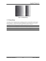
1
Manual No. 91000058-003
Revision A
October 1, 2001
The MegaPlusâ
Model 4.2i Camera
User’s Manual
Redlake MASD, Inc.
11633 Sorrento Valley Road
San Diego, California 92121-1097
Telephone: 800-854-7006 (USA and Canada only)
Fax: 858-481-6254.
Outside the USA: 858 481-8182
Internet: www.redlake.com
REDLAKE MASD, INC.
List of Manual Revisions
User’s Manual – Model 4.2i, Part Number 91000058-003
Revision
A
Date
10-01-01
EO No.
Notes
Reissued to reflect Redlake MASD, Inc. change and
general editorial changes.
RELATED DOCUMENTS
MegaPlus Remote Control Panel User’s Manual, Part Number 91000055-001
FCC DECLARATION OF CONFORMITY
This equipment has been tested and found to comply with the limits for a Class A digital device,
pursuant to Subpart B of Part 15 of the FCC rules. These limits are designed to provide
reasonable protection against harmful interference in a residential installation. This equipment
generates, uses and can radiate radio frequency energy, and if not installed and used in
accordance with the instructions, may cause harmful interference to radio communications.
However, there is no guarantee that interference will not occur in a particular installation. If this
equipment does cause harmful interference to radio or television reception, which can be
determined by turning the equipment off and on, the user is encouraged to try to correct the
interference by one or more of the following measures:
· Reorient or relocate the receiving antenna.
· Increase the separation between the equipment and receiver.
· Connect the equipment into an outlet on a circuit different from that to which the receiver
is connected.
· Consult the dealer or an experienced radio/TV technician for help.
This equipment has been certified to comply with the limits for a Class A computing device,
pursuant to FCC rules. In order to maintain compliance with FCC regulations, shielded cables
must be used with this equipment. Operation with non-approved equipment or unshielded cables
is likely to result in interference to radio and TV reception. The user is cautioned that changes
and modifications made to the equipment without the approval of the manufacturer could void the
user’s authority to operate this equipment.
Copyright ã 2001 Redlake MASD, Inc.
The information in this manual is for information purposes only and is subject to change without notice.
Redlake MASD, Inc. makes no warranty of any kind with regards to the information contained in this manual,
including but not limited to implied warranties of merchantability and fitness for a particular purpose.
Redlake MASD, Inc. shall not be liable for errors contained herein nor for incidental or consequential
damages from the furnishing of this information. No part of this manual may be copied, reproduced,
recorded, transmitted or translated without the express written permission of the Redlake MASD, Inc.
91000058-003 Revision A
ii
10/01/01
MegaPlus® Model 4.2i
PRECAUTIONS
WARNING!
LIFE SUPPORT APPLICATIONS POLICY
MegaPlus cameras are not authorized for and should not be used within life support
systems without the specific written consent of Redlake MASD, Inc.
NON-CRITICAL MEDICAL APPLICATIONS
MegaPlus cameras must be grounded to building earth ground while operating. This
camera has passed IEC 601 class B standards.
The voltage drop on the camera’s power return line must be less than 0.5 Volts DC.
Use a heavier gauge power cable to reduce the voltage drop below 0.5 Volts DC. For
medical applications, any power supply connected to the camera must meet IEC 601
specifications.
CAUTION: A laser beam focused on the sensor, either directly or by reflection, can cause
permanent damage to the sensor. Any laser powerful enough to produce
localized heating at the surface of the sensor will cause damage, even if the
camera power is off. A sensor damaged by laser light is NOT covered by the
warranty.
OPERATING TEMPERATURE
The MegaPlus camera is designed to operate satisfactorily in an environment where the ambient
temperature is between 0° and 35°C (32° and 95°F), with no water condensation present.
STORAGE TEMPERATURE
Do not store the equipment in an area where the temperature will drop below –25°C (-13°F) or
exceed 80°C (176°F). Do not allow moisture to condense on the system.
SHIPPING
When shipping, use a carton that protects the camera from shock and moisture, similar to the
carton in which the unit was originally delivered. Do not ship the equipment in a cargo area
where the temperature will drop below -25°C (-13°F) or exceed 80°C (176°F). Do not allow
moisture to condense on the system.
91000058-003 Revision A
iii
USER’S MANUAL
REDLAKE MASD, INC.
TABLE OF CONTENTS
1.
INTRODUCTION ............................................................................................................... 1-1
Introduction..................................................................................................................... 1-1
How to Use This Manual ................................................................................................ 1-1
2.
CONTROLS AND CONNECTORS ................................................................................... 2-1
2.1
Camera........................................................................................................................... 2-1
2.1.1
Mounting the Camera ............................................................................................. 2-1
2.1.2
Attaching the Lens .................................................................................................. 2-1
2.2
Camera Rear Panel ....................................................................................................... 2-2
2.2.1
Digital Interface ....................................................................................................... 2-2
2.2.2
Strobe Output.......................................................................................................... 2-2
2.2.3
DC Power Input....................................................................................................... 2-2
2.3
Cables ............................................................................................................................ 2-3
2.4
Hardware Setup ............................................................................................................. 2-4
2.5
Routine Maintenance ..................................................................................................... 2-5
3.
CAMERA OPERATION ..................................................................................................... 3-1
3.1
Introduction..................................................................................................................... 3-1
3.2
Serial Communications Protocol .................................................................................... 3-1
3.3
Error Messages .............................................................................................................. 3-1
3.4
Mode Control.................................................................................................................. 3-1
3.4.1
Trigger..................................................................................................................... 3-2
3.4.2
Continuous .............................................................................................................. 3-2
3.4.3
Control .................................................................................................................... 3-2
3.4.4
Parallel Interface ..................................................................................................... 3-2
3.5
Shutter............................................................................................................................ 3-3
3.6
Exposure ........................................................................................................................ 3-4
3.7
Trigger ............................................................................................................................ 3-5
3.8
Gain................................................................................................................................ 3-6
3.9
Black Level ..................................................................................................................... 3-6
3.10
Strobe Polarity ............................................................................................................ 3-7
3.11
Defect Correction........................................................................................................ 3-7
3.12
Reset .......................................................................................................................... 3-7
3.13
Save............................................................................................................................ 3-8
3.14
Status Query............................................................................................................... 3-8
3.15
Identification Query..................................................................................................... 3-8
3.16
Display Wedge ........................................................................................................... 3-9
4.
INTERFACE SPECIFICATIONS ....................................................................................... 4-1
4.1
Introduction..................................................................................................................... 4-1
4.2
Digital Video Connector ................................................................................................. 4-1
4.3
Digital Video Outputs ..................................................................................................... 4-1
4.4
Timing Outputs ............................................................................................................... 4-1
4.5
Control Inputs ................................................................................................................. 4-2
4.6
Mode Control Lines ........................................................................................................ 4-2
4.7
Sensor Specifications..................................................................................................... 4-9
4.8
Frame Rate Data.......................................................................................................... 4-10
4.8.1
Frame Rates ......................................................................................................... 4-10
4.8.2
Frame Transfer Time ............................................................................................ 4-10
4.8.3
Frame Repetition Rate.......................................................................................... 4-10
4.9
Timing Waveforms ....................................................................................................... 4-11
4.9.1
Exposure Timing ................................................................................................... 4-11
4.9.2
Frame Timing........................................................................................................ 4-12
4.9.3
Line Enable ........................................................................................................... 4-13
4.9.4
Pixel Timing .......................................................................................................... 4-13
4.10
Specifications ........................................................................................................... 4-14
1.1
1.2
91000058-003 Revision A
iv
10/01/01
MegaPlus® Model 4.2i
4.10.1
4.10.2
4.10.3
4.10.4
Video Performance ............................................................................................... 4-14
Camera Mechanical .............................................................................................. 4-14
Temperature ......................................................................................................... 4-14
Humidity ................................................................................................................ 4-14
LIST OF FIGURES
Figure 2-1. Camera Body ............................................................................................................. 2-1
Figure 2-2. C-Mount Lens Length Limit........................................................................................ 2-1
Figure 2-3. 4.2i Rear Panel .......................................................................................................... 2-2
Figure 2-4. 4.2i Cable Types ........................................................................................................ 2-3
Figure 2-5. Component Connection Diagram............................................................................... 2-4
Figure 3-1. Wedge Display ........................................................................................................... 3-9
Figure 4-1. Digital Interface Connector......................................................................................... 4-3
Figure 4-2. 68-Pin Digital Interface Cable .................................................................................... 4-4
Figure 4-3. 37-Pin Connector ....................................................................................................... 4-5
Figure 4-4. 9-Pin Connector ......................................................................................................... 4-5
Figure 4-5. 9-Pin PC COM Port/37-Pin Frame Grabber Cable .................................................... 4-6
Figure 4-6. 68-Pin Frame Grabber Connector ............................................................................. 4-7
Figure 4-7. 9-Pin PC COM Port/68-Pin (and 37-Pin) Frame Grabber Cable ............................... 4-8
Figure 4-8. Sensor Organization .................................................................................................. 4-9
Figure 4-9. Exposure Timing Waveform ......................................................................................4-11
Figure 4-10. Frame Timing (Continuous Mode) Waveform ........................................................ 4-12
Figure 4-11. Line Timing Waveform............................................................................................ 4-13
Figure 4-12. Pixel Clock Timing.................................................................................................. 4-13
LIST OF TABLES
Table 4-1. Mode Control Lines...................................................................................................... 4-2
Table 4-2. Digital Interface Connector Pinout (On Rear of Camera)............................................ 4-3
Table 4-3. 37-Pin Frame Grabber Cable Pinout ........................................................................... 4-5
Table 4-4. 9-Pin PC COM Port Cable Pinout................................................................................ 4-5
Table 4-5. 68-Pin Frame Grabber Interface Cable Pinout ............................................................ 4-7
Table 4-6. Sensor Specifications .................................................................................................. 4-9
91000058-003 Revision A
v
USER’S MANUAL
REDLAKE MASD, INC.
THIS PAGE INTENTIONALLY LEFT BLANK
91000058-003 Revision A
vi
10/01/01
MegaPlus® Model 4.2i
1. INTRODUCTION
1.1 Introduction
The Redlake MASD, INC. MegaPlus Camera, Model 4.2i, is a high-resolution solid-state camera
designed for scientific and industrial imaging applications. The system consists of a DC powered
Camera Head with a 68 pin digital interface. There are no manual user controls on the camera,
however the camera is operated by commands sent through a serial communication link. The
Camera is configured with either an RS232 or RS422 serial communications command input.
The operation of the MegaPlus Camera is very similar to the operation of a 35mm film camera. In
a film camera, the film is exposed by opening the shutter for a specific amount of time. The
shutter then closes and the film is advanced to the next frame. In the MegaPlus Camera, a builtin electromechanical shutter is used the same way.
The shutter opens exposing the sensor, then closes while the image captured by the sensor is
sent to a frame store device. The shutter in the MegaPlus Camera can be controlled internally or
externally.
The Camera features a high-resolution Charge-Coupled-Device (CCD) array containing 2029 (H)
x 2044 (V) light sensitive elements (pixels). These pixels are 9.0 microns square and have a
center-to-center spacing of 9.0 microns (100% fill ratio).
The equal horizontal and vertical geometry simplify measurements taken with the camera. The
benefit of having a 100% fill ratio is reduced aliasing, improved subpixel accuracy, and a 100%
light sensitive area. The Camera has an eight or ten bit digital video output. Exposure is
adjustable from 1 millisecond to 100 seconds in 1-millisecond increments using the internal
exposure control. Exposure times from 1 millisecond to the longest time practical can be had by
using an external exposure control signal.
The camera can be triggered asynchronously to capture high-speed events. Separate exposure
and readout cycles can be achieved by using a pulsed illumination light source such as a strobe.
An external strobe flash unit can be synchronized through a BNC connector on the rear panel of
the camera. This dramatically improves picture quality when the object being photographed is in
motion.
The MegaPlus Camera is ruggedly designed and can accommodate moderate amounts of shock
and vibration. Gaskets protect the camera’s interior components from dust, contaminants and
EMI.
1.2 How to Use This Manual
WARNINGS, CAUTIONS and NOTES
As you read this manual, you will notice that some of the information is presented as a
WARNING, CAUTION or NOTE. It is important that you understand the significance of these
terms.
A WARNING is important to the safety of anyone operating the Camera and should not be
disregarded under any circumstances.
A CAUTION is intended to alert you to an operation or condition that may cause loss of data or
harm to your Camera.
A NOTE contains information that is important to the operation of your Camera.
91000058-003 Revision A
1-1
USER’S MANUAL
REDLAKE MASD, INC.
Chapter 1 contains an introduction to the MegaPlus camera, an explanation of this manual, some
general precautions, and a warranty statement.
Chapter 2 explains the function of the controls and connectors of the MegaPlus Camera.
Chapter 3 is intended to give the user some insight into how to choose the correct mode of
operation for this MegaPlus camera. The correct mode of operation is defined as what will get
the imaging results you are looking for.
Chapter 4 details the specifications of the MegaPlus camera with the intent to give you all of the
information you require when using this camera.
91000058-003 Revision A
1-2
10/01/01
MegaPlus® Model 4.2i
NEW EQUIPMENT WARRANTY
REDLAKE MASD, INC. MEGAPLUS CAMERA
REDLAKE MASD, INC. (HEREAFTER REFERRED TO AS REDLAKE) WARRANTS THIS
CAMERA, AND ACCESSORIES MANUFACTURED BY REDLAKE, TO FUNCTION PROPERLY
FOR ONE YEAR FROM THE DATE OF SHIPMENT.
Redlake agrees to perform the following equipment warranty services in the United States.
1. Repair service: if shipped to us, repairs will be made at no charge.
2. Parts replacement: replacement parts installed under warranty will be provided at no charge.
THIS WARRANTY DOES NOT APPLY TO THE FOLLOWING CONDITIONS:
• Failure to operate the MegaPlus Camera in accordance with Redlake’s written instructions,
including environmental specifications listed in the User’s Manual.
• Evidence of the Camera being subjected to accidental damage, misuse or abuse.
• The Camera having been repaired or tampered with by persons other than Redlake personnel,
customer personnel trained by Redlake or without permission of Redlake.
• Shipping damage is not covered by this warranty. The purchaser has the responsibility to place
a claim of damage in shipment with the carrier.
REDLAKE MASD, INC. MAKES NO OTHER WARRANTIES, EXPRESSED, IMPLIED, OR OF
MERCHANTABILITY FOR THIS EQUIPMENT. IF THIS CAMERA DOES NOT FUNCTION
PROPERLY DURING THE WARRANTY PERIOD, REDLAKE WILL REPAIR IT WITHOUT
CHARGE ACCORDING TO THE TERMS STATED ABOVE. REPAIR WITHOUT CHARGE IS
REDLAKE’S ONLY OBLIGATION UNDER THIS WARRANTY. REDLAKE WILL NOT BE
RESPONSIBLE FOR ANY CONSEQUENTIAL OR INCIDENTAL DAMAGES RESULTING FROM
THE SALE, USE OR IMPROPER FUNCTIONING OF THIS EQUIPMENT EVEN IF LOSS OR
DAMAGE IS CAUSED BY THE NEGLIGENCE OR OTHER FAULT OF REDLAKE.
REDLAKE and MEGAPLUS are trademarks.
ã Redlake MASD, Inc. 2001
91000058-003 Revision A
1-3
USER’S MANUAL
REDLAKE MASD, INC.
THIS PAGE INTENTIONALLY LEFT BLANK
91000058-003 Revision A
1-4
10/01/01
MegaPlus® Model 4.2i
2. CONTROLS AND CONNECTORS
2.1 Camera
NOTE: A lens cap is installed on each camera to keep dust from getting on the optical sensor or
components when it is shipped. Remove the lens cap and install your lens in a dust free
environment.
2.1.1 Mounting the Camera
The MegaPlus Camera Head has four threaded screw holes for mounting, two on the bottom and
two on the top of the camera body. All holes accept 1/4-20 threaded screws. In most situations
the camera is attached to a tripod via the mounting point on the bottom of the Camera Head. It is
a good practice to mount the camera head on the tripod before attaching a lens to the camera.
Figure 2-1. Camera Body
2.1.2 Attaching the Lens
The camera can be purchased with either a C-mount or F-mount lens adapter. If your camera is
equipped with an F-mount lens adapter, insert the lens into the locking ring, then rotate the lens
counterclockwise until it clicks into position. To remove the lens, hold the release button down as
you rotate the lens clockwise.
If your camera is equipped with a C-mount lens adapter, screw the lens clockwise into the
adapter until you are no longer able to turn the lens with light pressure.
CAUTION: Some C-mount lenses may extend into the camera more than 0.20 inches
(5.08 mm), which may cause damage to internal optical components. Check the
dimension of any lens you plan to use as shown in Figure 2-2.
Figure 2-2. C-Mount Lens Length Limit
91000058-003 Revision A
2-1
USER’S MANUAL
REDLAKE MASD, INC.
Figure 2-3. 4.2i Rear Panel
2.2 Camera Rear Panel
2.2.1 Digital Interface
This is a 68-pin, high density, dual row, D type connector that interfaces the MegaPlus Camera to
a frame grabber board and serial communication interface for camera control. The frame grabber
board processes and displays video from the camera. A complete technical description of the
connector and the signals that it carries is contained in chapter four of this manual.
2.2.2 Strobe Output
The leading edge of this output signal can be used to fire a strobe light. This output signal is TTL
compatible and can drive a 50-ohm load. A strobe light with a flash duration of less than
1 millisecond is useful for capturing images of fast moving objects.
2.2.3 DC Power Input
This two-pin connector is the power input for the camera. The power supply voltage should be
between 12 and 28 volts DC measured at the connector on the camera rear panel. The current
draw is a maximum of 0.8 amps at the lowest input supply voltage and 0.3 amps at the highest
input supply voltage.
WARNING!
Reversing the polarity of the DC voltage input or voltage levels in excess of 30 volts may
permanently damage the camera
91000058-003 Revision A
2-2
10/01/01
MegaPlus® Model 4.2i
2.3 Cables
There are three different cables available to connect the MegaPlus Camera to your computer, as
shown in Figure 2-4 below.
Figure 2-4. 4.2i Cable Types
91000058-003 Revision A
2-3
USER’S MANUAL
REDLAKE MASD, INC.
2.4 Hardware Setup
Follow the instructions supplied by the frame grabber manufacturer when you are using their
cables to install your camera. If using Redlake supplied cables, connect the camera as shown in
Figure 2-5 below.
Figure 2-5. Component Connection Diagram
91000058-003 Revision A
2-4
10/01/01
MegaPlus® Model 4.2i
2.5 Routine Maintenance
There are no user serviceable parts in the camera. Should the shutter malfunction, the camera
must be returned to the factory for repair.
The lens should be cleaned according to good photographic practices. This will help keep your
camera producing top quality pictures.
The camera can be ordered from the factory with an infrared filter installed in the lens mount. If an
infrared filter was not ordered originally, a piece of clear glass will be installed in place of the filter.
The filter or its glass replacement keep the interior of the camera sealed from dust and should
never be removed in other than a clean room environment. Because of the high resolution of the
camera, a single speck of dust on the sensor is very noticeable.
If you need to use different filters in your application from time to time, we recommend that you
order the camera with the clear glass installed. The spectral sensitivity can then be changed by
exchanging filters on the end of the lens as in 35mm photography.
91000058-003 Revision A
2-5
USER’S MANUAL
REDLAKE MASD, INC.
THIS PAGE INTENTIONALLY LEFT BLANK
91000058-003 Revision A
2-6
10/01/01
MegaPlus® Model 4.2i
3. CAMERA OPERATION
3.1 Introduction
The MegaPlus Camera, Model 4.2i does not have any manual controls. Camera operation is
accomplished by commands sent to the camera through a serial data link from a personal
computer. In this chapter we will present the various operating modes of the camera with an
explanation of the function followed by the command sequence that must be transmitted by the
computer. The control lines to the camera can be configured as an RS232 or an RS422 serial
data link. The camera is ordered from the factory configured one way or the other. The
command syntax is the same in either case.
3.2 Serial Communications Protocol
The camera uses a full duplex UART type asynchronous system, using standard nonreturn-tozero (NRZ) format (one start bit, eight data bits, one stop bit, no parity). The baud rate is fixed at
9600. The character code is based on the ASCII standard.
The character flow control protocol is XON/XOFF. XON is assigned DC1 (control-Q) and XOFF
is assigned DC3 (control-S). The receiver sends the XOFF character when it wants the sender to
pause in sending data and an XON character when it wants the sender to resume.
The camera will recognize a command as three command characters, followed by a space bar
character, followed by an argument that consists of one or more characters, ended by the
carriage return and line feed characters. The camera responds to a valid command with a
carriage return and line feed (CR-LF).
The camera will recognize a query as three command characters, followed by the question mark
character, then ended by the carriage return character.
The camera responds to a query with three command characters, followed by a space bar character, followed by an
argument that consists of one or more characters, then ended by carriage return character and line feed (CR-LF).
3.3 Error Messages
The camera can respond to an erroneous command or query in one of three possible ways.
MESSAGE FROM CAMERA
ERROR-SYNTAX
ERROR-ARGUMENT OUT OF RANGE
EXPLANATION
The camera cannot make sense of the command.
The command is recognized, but the argument is
out of range or indecipherable.
ERROR-TRANSMISSION
The receiver detected a transmission error such
as buffer overflow, parity, noise, or framing
3.4 Mode Control
The MegaPlus Camera operates in one of three modes, TRIGGER, CONTINUOUS, or
CONTROL. The mode of operation is selected by the mode command. The mode command’s
fourth option, PARALLEL INTERFACE, delegates mode selection to three control lines, MC0 MC2, input through the Digital Interface Connector
91000058-003 Revision A
3-1
USER’S MANUAL
REDLAKE MASD, INC.
3.4.1 Trigger
Each exposure is started by a signal connected to the EXPOSE input pins of the “Digital
Interface” connector on the rear panel of the camera. The exposure command sets the exposure
time and, indirectly, the frame rate.
The EXPOSE input sets the start time for each frame of video. When the trigger signal lasts
longer than the combined exposure and readout time, the camera will continue to take exposures
until the trigger signal goes away.
The trigger mode of operation is used to capture a single picture or sequence of pictures. If the
object that you are trying to capture is fast moving, a strobe light may be used to freeze the
action. The short flash duration (sometimes less than 50 microseconds) of a strobe is the key to
minimizing blur caused by speedy subjects. The Strobe Output on the rear panel of the camera
can be used to start the strobe flash.
3.4.2 Continuous
The continuous mode of operation is useful when the operator wishes to monitor an ongoing
event. The camera will repeatedly take pictures as fast as the exposure time selected allows.
The exposure command sets the exposure time and, indirectly, the frame rate. Each new
exposure starts as soon as the previous image has been transferred to the camera output by the
camera electronics.
3.4.3 Control
The start and exposure time of each picture is controlled directly by the user. Control is
accomplished by the EXPOSE input pins in the “Digital Interface” connector on the rear panel of
the camera. The exposure time is equal to the time the EXPOSE input signal is true.
3.4.4 Parallel Interface
This option provides compatibility with previous models of the MegaPlus Camera. This mode
enables limited camera control by a frame grabber board installed in a host computer. When the
mode is set to Parallel Interface, the state of the control lines MC0, MC1, and MC2 determines
the operating mode of the Camera. See page 4.2 for details on control lines MC0 - MC2.
TYPE IN:
MDE xx
RESPONSE
CR-LF
MDE?
EXPLANATION
Sets the mode as determined by the argument TR,
CS, DC, PI.
Queries the current mode setting.
MDE xx
Means the mode is set as indicated.
Sample commands with arguments:
MDE TR
MDE CS
MDE CD
MDE PI
Sets the mode to TRIGGER.
Sets the mode to CONTINUOUS.
Sets the mode to CONTROLLED.
Delegates mode control to Control Lines MC0 – MC2.
91000058-003 Revision A
3-2
10/01/01
MegaPlus® Model 4.2i
3.5 Shutter
The MegaPlus Camera may be operated with the shutter on or off. When the shutter is off, the
shutter blades can be locked open or closed. The shutter is controlled by the SHE command in
the CONTINUOUS, CONTROL and TRIGGER modes of operation. When the camera is set to
LINE operation, the shutter is controlled by the command line MC2.
When the shutter is on, the exposure time is set by the exposure command for both the
CONTINUOUS and TRIGGER modes of operation. When the camera is operated in the
CONTROL mode, the exposure lasts for as long as the EXPOSE input to the camera is “true”.
In general, the shutter should be turned off with the blades open if you are working in a darkened
area with a light source that is flashed. The camera is always gathering light even as an image is
being read from the sensor. If there is light on the subject between exposures, the shutter should
be used to prevent image smear. If you need to acquire a dark current frame, turn the shutter off
with the blades closed and transfer a frame.
TYPE IN:
SHE xx
RESPONSE
CR-LF
SHE?
EXPLANATION
Enables or disables the shutter as determined by the
argument ON, FO, or FC.
Queries the current shutter setting.
SHE xx
Means the shutter is enabled or disabled as indicated.
Sample commands with arguments:
SHE ON
SHE FO
SHE FC
Enables the Shutter.
Disables the Shutter and locks it in the open position.
Disables the Shutter and locks it in the closed position.
91000058-003 Revision A
3-3
USER’S MANUAL
REDLAKE MASD, INC.
3.6 Exposure
This command sets the exposure time of the camera in increments of one millisecond. The
exposure times can be any value between one millisecond and one hundred seconds. This
exposure time setting affects the CONTINUOUS and TRIGGER modes only. The camera
produces the most uniform picture when the exposure time is between 50 and 200 milliseconds.
The maximum frame rate is directly related to exposure time. The maximum frame rate with the
exposure set for 50 milliseconds is 1.8 frames per second. For an exposure time of 500
milliseconds, the fastest frame rate becomes 1.0 frame per second.
Frame Rate = 1/(485 milliseconds + exposure time + shutter transition time)
When your application involves low light levels and a subject that is not moving, exposure times
of more than one second may be necessary. As you push the exposure time beyond one
second, you may notice that image quality deteriorates. This is caused by sensor dark current
accumulating over time. The CONTROL mode allows you to extend the exposure time beyond
100 seconds, but you should understand that picture quality degrades with the longer exposure
times.
TYPE IN:
EXExxxxxx
RESPONSE
CR-LF
EXE?
EXPLANATION
Sets the exposure in one millisecond increments
using the argument with a range from 1 to 100000.
Queries the current Exposure setting.
EXExxxxxx
Means the exposure is set as indicated.
Sample commands with arguments:
EXE 1
EXE 100000
Sets the Exposure to one millisecond.
Sets the Exposure to one hundred thousand milliseconds (100 seconds).
91000058-003 Revision A
3-4
10/01/01
MegaPlus® Model 4.2i
3.7 Trigger
This command enables and sets the polarity of the EXPOSE input on the Digital Interface
Connector on the rear panel of the camera.
TYPE IN:
TRM x
TRE x
RESPONSE
CR-LF
EXPLANATION
Sets the EXPOSE input signal in the Digital
Connector to positive (TRM P) or negative (TRM N)
logic. Either command enables the expose input
port pins if they were disabled.
CR-LF
TRE 0 forces an exposure. TRE 1 resets the
exposure to transfer/idle. Either command disables
the EXPOSE input. Use the TRM command to turn
the EXPOSE input back on.
TRM?
Queries the current EXPOSE polarity.
TRM P
TRM N
TRM O
TRE?
Means EXPOSE signal is set to positive logic
Means EXPOSE signal is set to negative logic.
Means EXPOSE input port has been disabled. This
can only occur if TRE 0 or 1 has been executed.
Queries the current state of the TRIGGER
command.
TRE 0
TRE 1
Means an exposure is taking place.
Means the camera is in the Transfer Frame and
then Idle state.
Sample commands with arguments:
COMMAND
TRM P
TRM P
TRM N
TRM N
EXPOSE (+) INPUT
HIGH
LOW
HIGH
LOW
ACTION
Expose.
Transfer frame and then idle.
Transfer frame and then idle
Expose.
NOTE: Trigger must be set to positive, TRM P, if you are using a frame grabber designed for the
MegaPlus 4.2i camera.
91000058-003 Revision A
3-5
USER’S MANUAL
REDLAKE MASD, INC.
3.8 Gain
The gain of the camera is variable in 2dB steps between 0dB and 24dB. The normal gain
position is 6dB. 0dB halves the gain, 12dB multiplies the gain by 2, 18dB multiplies the gain by 4
and 24dB multiplies the gain by 8. A change in gain of 6dB is the same as changing the lens
aperture by one f-stop.
As you increase the gain of the camera the noise in the picture will increase. By adjusting the
camera gain, the operator can optimize the signal to noise ratio and the sensitivity of the camera
for the application.
TYPE IN:
GAE xx
RESPONSE
CR-LF
GAE?
EXPLANATION
Sets the gain control in 2dB increments. The range of
values is 0 to 24. Only even numbers are valid
Queries the current gain setting.
GAE xx
Indicates that the gain is set to the value given in dB.
Sample commands with arguments:
GAE 0
GAE 4
GAE 24
Sets the camera gain to 0dB.
Sets the camera gain to 4dB.
Sets the camera gain to 24dB.
3.9 Black Level
The black level control functions much like the brightness control on a television set. To get
reasonable results under most circumstances, use the BKF or fixed black level. The fixed video
black level is set at the factory so that the output video is just above the black clipping level with
the lens capped. The black level can be varied over a range of plus or minus 50 percent of peak
white video. This adjustment range lets the user compensate for poor lighting.
TYPE IN:
BKF
RESPONSE
CR-LF
EXPLANATION
Sets the black level to an internal fixed value of
approximately 50 counts above zero for 10 bits or 12
for 8 bits.
BKE xxxx
CR-LF
Sets the black level as determined by the argument
with a range from –2048 to +2047.
BKE?
BKF
BKE xxxx
Queries the current black level setting.
Means the black level is at the factory preset level.
Means black level externally set to the value
indicated.
COMMAND
APPROX. OUTPUT OFFSET
8-Bits
10-Bits
BKE -2048
BKE 0
BKE 2047
-128 counts
0 counts
+127 counts
-512 counts
0 counts
+511 counts
NOTE: The video will be clipped to 0 counts until it overcomes a negative offset. The video will
be offset towards white by a positive offset.
91000058-003 Revision A
3-6
10/01/01
MegaPlus® Model 4.2i
3.10 Strobe Polarity
The STROBE OUTPUT on the rear panel of the camera provides a trigger signal for the user’s
stroboscopic light source. The polarity of the strobe signal is set by this command. Use the
leading edge of the strobe signal as the trigger point, because the trailing edge may vary. The
Strobe output is capable of driving a 50-ohm load.
TYPE IN:
STP x
RESPONSE
CR-LF
STP?
STP P
STP N
EXPLANATION
Sets the polarity of the strobe trigger pulse to positive
(STP P) or to negative (STP N).
Queries the strobe trigger output polarity.
Means the strobe output is a high going pulse.
Means the strobe output is a low going pulse.
Sample commands with arguments:
STP P
STP N
Makes the strobe output a high going pulse.
Makes the strobe output a low going pulse.
NOTE: The STROBE OUTPUT must be set to positive, STP P, if you are using a strobe
designed for use with the MegaPlus 4.2i camera.
3.11 Defect Correction
Occasionally, sensors are not perfect and have some areas that react differently to light. These
problem pixels are usually seen as a column that is different in intensity than the immediately
adjacent area. It is possible to characterize a sensor identifying the defective columns and then
program their locations into the camera at the factory. When defect correction is turned on, the
camera replaces the defective areas with information derived from nearby pixels making the
defects less noticeable.
TYPE IN:
DEF xx
RESPONSE
CR-LF
DEF?
DEF ON
DEF OF
EXPLANATION
Enables (DEF ON) or Disables (DEF OF) Defect
Correction.
Queries the state of Defect Correction.
Means the Defect Correction is enabled.
Means the Defect Correction is disabled.
Sample commands with arguments:
DEF ON
DEF OF
Turns on Defect Correction.
Turns off Defect Correction.
3.12 Reset
TYPE IN:
RST
RESPONSE
CR-LF
91000058-003 Revision A
EXPLANATION
Resets the camera to the settings as last saved.
Removing and then restoring power also performs a
reset.
3-7
USER’S MANUAL
REDLAKE MASD, INC.
3.13 Save
TYPE IN:
SAV
RESPONSE
CR-LF
EXPLANATION
Saves the current camera settings to EEPROM; these
settings will be recalled by a RESET or by turning the
camera power on.
NOTE: The EEPROM used by the SAVE command has a finite life of roughly 10,000 erase and
program cycles. We recommend that the SAVE command be used occasionally to store
your most generally applicable setup and not as a daily routine.
3.14 Status Query
The Status Query command enables the user to get all of the camera operating parameter
information with a single command.
TYPE IN:
STS?
RESPONSE
DEF xx
GAE xxx
BKE xxxx
MDE xx
SHE xx
EXE xx
TRM x
TRE x
STP x
SCP x
EXPLANATION
Gives complete camera status with one query. The
following parameters are transmitted with a carriage
return after each parameter:
Shows Defect Concealment status.
Shows Gain setting.
Shows Black Level setting.
Shows the operating Mode.
Shows the Shutter status
Shows the Exposure time.
Shows the Trigger logic polarity.
Shows the Exposure state.
Shows the polarity of the Strobe Pulse.
Shows the communications protocol.
A typical reply to STS? would be as follows:
DEF ON
GAE 6
BKE 610
MDE CD
SHE ON
EXE 100
TRM P
TRE 1
STP N
SCP 232
3.15 Identification Query
TYPE IN:
IDN?
RESPONSE
MegaPlus Model
4.2i, Vx.xx
91000058-003 Revision A
EXPLANATION
Queries the camera model number and software
version.
3-8
10/01/01
MegaPlus® Model 4.2i
Figure 3-1. Wedge Display
3.16 Display Wedge
The wedge command displays linearly increasing gray scales in each quadrant of the image as
shown in Figure 3-1. This function is useful for aligning the camera image to a frame grabber.
The display wedge defaults to OFF when the power to the camera is turned off.
TYPE IN:
WDG ON
RESPONSE
CR-LF
WDG OF
CR-LF
WDG?
91000058-003 Revision A
EXPLANATION
Means the wedge is being displayed.
Means the camera is imaging.
Queries the state of the wedge display.
3-9
USER’S MANUAL
REDLAKE MASD, INC.
THIS PAGE INTENTIONALLY LEFT BLANK
91000058-003 Revision A
3-10
10/01/01
MegaPlus® Model 4.2i
4. INTERFACE SPECIFICATIONS
4.1 Introduction
Chapter four gives you the information needed to interface the MegaPlus Camera, Model 4.2i to a
frame grabber device. The relationship between the video outputs and the synchronization
outputs of the camera are presented in the following order:
• DIGITAL INTERFACE CONNECTOR
• MODE CONTROL
• EXPOSURE TIMING
• FRAME TIMING
• LINE TIMING
• PIXEL TIMING
The MegaPlus Camera, Model 4.2i is a high-resolution black and white still camera presenting an
eight bit (or optional 10 bit) digital video output. Each frame has 2,029 columns and 2,044 rows
of pixels (picture elements) containing valid video data.
4.2 Digital Video Connector
All the signals referred to in this section are present at the Digital Interface connector on the rear
panel of the camera. Table 1 lists each signal and its pin number. The connector for this port is a
68 pin, high density, dual row, D type connector. This connector is the same as that used for the
“SCSI-2 B cable” interface. The connector has .050 inch (12.7mm) pin spacing and a D-type shell
that is 2.5 inches (63.5mm) long. We have taken precautions to prevent damage to the CCU
should a SCSI device accidentally be connected to this port.
4.3 Digital Video Outputs
The digital video output of the camera has ten bits labeled MSB through MSB-9. These signals
are output as differential pairs with signal levels conforming to the RS422 specification. The
noninverting part of the differential pair is present on output (+), while the inverting part of the
differential pair is present on output (-).
MSB is the Most Significant Bit and MSB-7 is the least significant bit in this camera configuration.
All frame grabbers designed to work with this and future MegaPlus Cameras should be MSB
justified. MSB will always be the most significant bit in all eight or ten bit camera configurations.
4.4 Timing Outputs
There are three timing outputs presented on the Digital Interface connector. They are FRAME
ENABLE (FRME ENA), LINE ENABLE (LINE ENA) and PIXEL DATA STROBE (PIX DATA
STRB). These signals are output as differential pairs with signal levels conforming to the RS422
specification. The noninverting part of the differential pair is present on output (+), while the
inverting part of the differential pair is present on output (-). A signal is true when the (+) line is
more positive than the (-) line.
91000058-003 Revision A
4-1
USER’S MANUAL
REDLAKE MASD, INC.
4.5 Control Inputs
The control input EXPOSE is provided as a means of externally controlling the exposure of the
camera. This input is designed to accept RS-422 differential or, for backwards compatibility,
single ended TTL. To drive this input differentially, connect both the (+) and (-) inputs to an
RS-422 driver. When the (+) input is more positive than the (-) input the camera is exposing.
When the (+) input is more negative than the (-) input the camera performs a frame transfer and
then idles.
To drive the EXPOSE input with a single ended TTL signal source, connect one input to a TTL
driver and leave the other input floating. If the (+) input (pin 30) is driven, then a TTL high will
start an exposure or if the (-) input (pin 64) is driven, then a TTL low will start an exposure.
4.6 Mode Control Lines
The operating mode of the camera is set by the MDE command. Issuing an MDE PI command
will delegate mode control to the MC0-MC2 mode control lines. MC0, MC1, and MC2 provide
backward compatibility with earlier MegaPlus Camera control signals. Each of these inputs is
designed to accept TTL level signals referenced to ground at the connector. MC0 and MC1 set
the operating mode and MC2 enables the shutter. The truth table for the control lines is as
follows:
Table 4-1. Mode Control Lines
MC2 (Pin 33)
TTL Input
Low (0 volts)
Low (0 volts)
Low (0 volts)
Low (0 volts)
High (+5 volts)
High (+5 volts)
High (+5 volts)
High (+5 volts)
MC1 (Pin 32)
TTL Input
Low (0 volts)
Low (0 volts)
High (+5 volts)
High (+5 volts)
Low (0 volts)
Low (0 volts)
High (+5 volts)
High (+5 volts)
MC0 (Pin 31)
TTL Input
Low (0 volts)
High (+5 volts)
Low (0 volts)
High (+5 volts)
Low (0 volts)
High (+5 volts)
Low (0 volts)
High (+5 volts)
Shutter
Operation
Enabled
Enabled
Enabled
Enabled
Off, blades open
Off, blades open
Off, blades open
Off, blades open
Operating
Mode
Controlled
Triggered
Continuous
Continuous
Controlled
Triggered
Continuous
Continuous
NOTE: Redlake, MASD, Inc. does not recommend using MC0 through MC2 for mode control in
new designs for MegaPlus cameras. The serial data port, with its complete command
set, provides a more useful control interface.
91000058-003 Revision A
4-2
10/01/01
MegaPlus® Model 4.2i
Table 4-2. Digital Interface Connector Pinout (On Rear of Camera)
PIN
1
2
3
4
5
6
7
8
9
10
11
12
13
14
15
16
17
18
19
20
21
22
23
24
25
26
27
28
29
30
31
32
33
34
SIGNAL NAME
GROUND
MSB (+)
MSB-1 (+)
MSB-2 (+)
MSB-3 (+)
MSB-4 (+)
MSB-5 (+)
MSB-6 (+)
MSB-7 (+)
MSB-8 (+)
MSB-9 (+)
GROUND
Not Used
Not Used
Not Used
Not Used
Not Used
Not Used
Not Used
Not Used
Not Used
SER CNTRL OUT (+)
SER CNTRL IN (+)
Not Used
FRME ENA (+)
LINE ENA (+)
Not Used
Not Used
PIX DATA STRB (+)
EXPOSE (+)
MC0
MC1
MC2
GROUND
PIN
35
36
37
38
39
40
41
42
43
44
45
46
47
48
49
50
51
52
53
54
55
56
57
58
59
60
61
62
63
64
65
66
67
68
SIGNAL NAME
GROUND
MSB (-)
MSB-1 (-)
MSB-2 (-)
MSB-3 (-)
MSB-4 (-)
MSB-5 (-)
MSB-6 (-)
MSB-7 (-)
MSB-8 (-)
MSB-9 (-)
GROUND
Not Used
Not Used
Not Used
Not Used
Not Used
Not Used
Not Used
Not Used
Not Used
SER CNTRL OUT (-)
SER CNTRL IN (-)
Not Used
FRME ENA (-)
LINE ENA (-)
Not Used
Not Used
PIX DATA STRB (-)
EXPOSE (-)
Not Used
Not Used
Not Used
GROUND
SOURCE
Camera
Camera
Camera
Camera
Camera
Camera
Camera
Camera
Camera
Camera
Camera
Camera
Camera
User
Camera
Camera
Camera
User
User
User
User
Camera
Figure 4-1. Digital Interface Connector
91000058-003 Revision A
4-3
USER’S MANUAL
REDLAKE MASD, INC.
(For use with 8 or 10 bit, RS422 Cameras)
(Refer to Table 4-2 for Pinout)
Figure 4-2. 68-Pin Digital Interface Cable
91000058-003 Revision A
4-4
10/01/01
MegaPlus® Model 4.2i
Table 4-3. 37-Pin Frame Grabber Cable Pinout
PIN
1
2
3
4
5
6
7
8
9
10
11
12
13
14
15
16
17
18
19
SIGNAL NAME
PIX DATA STRB (+)
LINE ENA (+)
FRME ENA (+)
GROUND
Not Used
Not Used
Not Used
MSB (+)
MSB-1 (+)
MSB-2 (+)
MSB-3 (+)
MSB-4 (+)
MSB-5 (+)
MSB-6 (+)
MSB-7 (+)
GROUND
EXPOSE
MC0
MC2
PIN
20
21
22
23
24
25
26
27
28
29
30
31
32
33
34
35
36
37
SIGNAL NAME
PIX DATA STRB (-)
LINE ENA (-)
FRME ENA (-)
GROUND
Not Used
Not Used
Not Used
MSB (-)
MSB-1 (-)
MSB-2 (-)
MSB-3 (-)
MSB-4 (-)
MSB-5 (-)
MSB-6 (-)
MSB-7 (-)
GROUND
Not Used
MC1
SOURCE
Camera
Camera
Camera
Camera
Camera
Camera
Camera
Camera
Camera
Camera
Camera
Camera
Camera
User
User
User
(37-Pin female D subminiature connector as viewed at the end of the cable)
Figure 4-3. 37-Pin Connector
Table 4-4. 9-Pin PC COM Port Cable Pinout
PIN
1
2
3
4
5
SIGNAL NAME
Open
Camera (TX) from Camera
Camera (RX) from User
Open
Camera Ground
PIN
6
7
8
9
SIGNAL NAME
Open
Connected to Pin 8
Connected to Pin 7
Open
(9-Pin female D subminiature connector as viewed at the end of the cable)
Figure 4-4. 9-Pin Connector
91000058-003 Revision A
4-5
USER’S MANUAL
REDLAKE MASD, INC.
(Refer to Tables 4-3 and 4-4 for Pinouts)
Figure 4-5. 9-Pin PC COM Port/37-Pin Frame Grabber Cable
91000058-003 Revision A
4-6
10/01/01
MegaPlus® Model 4.2i
Table 4-5. 68-Pin Frame Grabber Interface Cable Pinout
PIN SIGNAL NAME
1
GROUND
2
MSB (+)
3
MSB-1 (+)
4
MSB-2 (+)
5
MSB-3 (+)
6
MSB-4 (+)
7
MSB-5 (+)
8
MSB-6 (+)
9
MSB-7 (+)
10
MSB-8 (+)
11
MSB-9 (+)
12
GROUND
13
Not Used
14
Not Used
15
Not Used
16
Not Used
17
Not Used
18
Not Used
19
Not Used
20
Not Used
21
Not Used
22
Not Used
23
Not Used
24
Not Used
25
FRME ENA (+)
26
LINE ENA (+)
27
Not Used
28
Not Used
29
PIX DATA STRB (+)
30
EXPOSE (+)
31
MC0
32
MC1
33
MC2
34
GROUND
(N/C = Not Connected)
PIN
35
36
37
38
39
40
41
42
43
44
45
46
47
48
49
50
51
52
53
54
55
56
57
58
59
60
61
62
63
64
65
66
67
68
SIGNAL NAME
GROUND
MSB (-)
MSB-1 (-)
MSB-2 (-)
MSB-3 (-)
MSB-4 (-)
MSB-5 (-)
MSB-6 (-)
MSB-7 (-)
MSB-8 (-)
MSB-9 (-)
GROUND
Not Used
Not Used
Not Used
Not Used
Not Used
Not Used
Not Used
Not Used
Not Used
SER CNTRL OUT (-)
SER CNTRL IN (-)
Not Used
FRME ENA (-)
LINE ENA (-)
Not Used
Not Used
PIX DATA STRB (-)
EXPOSE (-)
Not Used
Not Used
Not Used
GROUND
SOURCE
Camera
Camera
Camera
Camera
Camera
Camera
Camera
Camera
Camera
Camera
Camera
Camera
Do Not Use
Do Not Use
Camera
Camera
Camera
User
User
User
User
Camera
Figure 4-6. 68-Pin Frame Grabber Connector
91000058-003 Revision A
4-7
USER’S MANUAL
REDLAKE MASD, INC.
(Refer to Table- for Pinout)
Figure 4-7. 9-Pin PC COM Port/68-Pin (and 37-Pin) Frame Grabber Cable
91000058-003 Revision A
4-8
10/01/01
MegaPlus® Model 4.2i
4.7 Sensor Specifications
Table 4-6. Sensor Specifications
ITEM
Imaging Device
DESCRIPTION
Solid-state charge-coupled device (CCD); front illuminated
full-frame architecture
Total Pixel Clock Count
4,849,664 (2,368H x 2,048V)
Light-Sensitive Pixels
4,147,276 (2,029H x 2,044V)
Elements Transferred Per Line
2,368 pixel clock pulses in each line transfer (2,029 for
active video + 339 for sync and blanking)
Lines Transferred Per Frame
2,048 (Four dark lines at the bottom)
Pixel Size
9.0 x 9.0 microns (square format)
Center-to-Center Pixel Spacing
9.0 microns, vertical and horizontal (unity fill-ratio)
Active Area
18.5mm(H) x 18.5mm(V) photosensitive area
(100% fill factor)
Figure 4-8. Sensor Organization
91000058-003 Revision A
4-9
USER’S MANUAL
REDLAKE MASD, INC.
4.8 Frame Rate Data
4.8.1 Frame Rates
The frame rate of the camera is the number of images that can be taken per unit of time. The
camera must transfer a full frame before it is able to make a new exposure and transfer the new
frame. The rate depends on both the frame transfer time and the exposure time.
4.8.2 Frame Transfer Time
The frame transfer time is a constant. It is the number of pixels in a frame divided by the rate
they are clocked out.
2,048 lines x 2,368 clock intervals per line
10 MHz
= Transfer Time
= 4,849,664 pixels @ 10 MHz
= 485 milliseconds
4.8.3 Frame Repetition Rate
The frame repetition rate depends on both the frame transfer time and the exposure time.
1
(Exposure time + frame transfer time + shutter transit time)
= Frame Rate
For exposures that are much shorter than the frame transfer time and when the shutter is off, the
frame transfer time dominates the above equation and the frame rate approaches the maximum:
1/(485) milliseconds
=
2.1 frames per second
For an exposure time of 50 milliseconds, the frame rate becomes:
1/(485 + 50 + 15) milliseconds
=
1.8 frames per second
For an exposure time of 500 milliseconds, the frame rate becomes”
1/(485 + 500 + 15) milliseconds
=
1.0 frames per second
It is important to remember that each line has 2,029 active pixels and that there are 2,044 lines of
valid video data in each frame. The last four lines are not light sensitive.
91000058-003 Revision A
4-10
10/01/01
MegaPlus® Model 4.2i
4.9 Timing Waveforms
4.9.1 Exposure Timing
The start and stop of exposure time are synchronized with the falling edge of LINE ENA (+). The
exposure time interval, whether generated internally or externally, is sampled at the falling edge
of LINE ENA (+). Any start or stop exposure command occurring less than 250 nanoseconds
before the falling edge of LINE ENA (+) may go undetected. This means that the camera will not
respond to the start or stop command until another line has been processed.
All exposure events are quantized in steps of one line time or 236.8 µsec. This normally has no
effect on exposure because one or two line times (0.2 to 0.4 ms) is a small percentage of the total
10 to 500 millisecond exposure time.
NOTE: The EXPOSE input pulse must be wide enough to be seen by at least one horizontal
SYNC, which occurs once every 236.8 µsec. A pulse width of less than 236.8 µsec may
be missed.
Figure 4-9. Exposure Timing Waveform
91000058-003 Revision A
4-11
USER’S MANUAL
REDLAKE MASD, INC.
4.9.2 Frame Timing
The FRAME ENABLE signal is low while the array is exposed. The duration of this low state is
variable and includes the user defined exposure time.
A complete frame of video data is transferred to the camera outputs while FRAME ENA (+) is
high. The camera takes 485 milliseconds to transfer a complete image from the sensor array to
the output. FRAME ENA (+) will be low while the camera is idle and while the camera is
exposing.
The first pixel that is output in the frame transfer sequence is the pixel that belongs in the upper
left-hand corner of the video display. Each row of video data is output from left to right and the
rows are presented from top to bottom. The last pixel of the frame is placed in the lower right
hand corner of the video display.
The video is transferred by shifting each row up one row. The top row is shifted into a register
that performs the parallel to serial conversion as it outputs the video data. The LINE ENA (+)
signal is held high for the time that it takes to output one row of video. The LINE ENA (+) signal
has a period of 236.8µsec and runs continuously even if there is no video to be output.
Figure 4-10. Frame Timing (Continuous Mode) Waveform
91000058-003 Revision A
4-12
10/01/01
MegaPlus® Model 4.2i
4.9.3 Line Enable
This is the Horizontal Sync for the camera. This signal runs continuously to allow external
equipment to “phase lock” with the camera if desired. It is not affected by the camera mode or by
any state the camera may be in (idle, exposing, or transferring).
When LINE ENA (+) is low, all lines in the sensor are shifted upward in parallel one line. The top
line is shifted into the horizontal output shift register.
When LINE ENA (+) is high, the information in that horizontal shift register is clocked serially to
the camera’s output circuits.
Image data is valid only when both FRAME ENABLE and LINE ENABLE are high, the rest of the
time the data are meaningless.
Figure 4-11. Line Timing Waveform
4.9.4 Pixel Timing
PIXEL DATA STROBE is a 10 MHz square wave that runs continuously. This clock drives the
circuitry that identifies pixels, counts lines, and synchronizes the internal states of the camera.
Valid digital data should be sampled at the rising edge of PIX DAT STRB (+).
Figure 4-12. Pixel Clock Timing
91000058-003 Revision A
4-13
USER’S MANUAL
REDLAKE MASD, INC.
4.10 Specifications
4.10.1 Video Performance
Black Level:
Gamma:
Scanning:
Synchronization:
Dynamic Range:
Pixel Clock Rate:
Frame Rate:
Clamped to black reference at the start of each frame.
Unity.
Non-Interlaced progressive scan
Internal.
Greater than 65dB at the input of the A/D Converter.
10 MHz.
2.1 frames per second @ strobe illumination
1.8 frames per second @ 50 millisecond exposure time
1.0 frames per second @ 500 millisecond exposure time
NOTE: Frame Rate = 1/(485 milliseconds + exposure time + 15 millisecond shutter transition time).
4.10.2 Camera Mechanical
Housing:
Dimensions:
F-mount:
C-Mount:
Lens:
Weight:
Mount:
Vibration:
Shock:
All aluminum gasket sealed case.
4.45”H x 3.90”W x 5.84”L
(113.0 x 99.1 x 148.3mm)
4.45”H x 3.90”W x 4.68”L
(113.0 x 99.1 x 118.8mm)
C-Mount or F-Mount.
Approximately 3 pounds (1.26 Kg).
Four ¼ - 20 threaded holes (2 on top/2 on bottom).
3G, sinusoidal from 5 to 150 Hz.
20G (nonoperating).
4.10.3 Temperature
Operating:
Storage:
0 to 35°C (32 to 95°F), non-condensing
(Image quality will degrade with increasing temperature)
-25 to +80°C (-13 to 176°F), non-condensing.
4.10.4 Humidity
Operating:
Storage:
91000058-003 Revision A
<80% @ 35°C (95°F).
<40% @ 80°C (176°F).
4-14
10/01/01