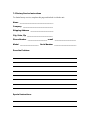
1
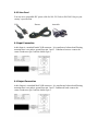
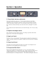
Retro Instruments, Inc. User’s Manual 176 Tube Limiting Amplifier Retro Instruments, Inc. 176 Tube Limiting Amplifier User’s Manual 2008 Retro Instruments, Inc. P.O. Box 5066 Modesto, CA 95352-5066 USA (209) 810-3344 Manual Revisions Revision Print Date Initial Release December 29, 2008 Notices 2008 Retro Instruments, Inc. All rights reserved. No part of this document may be reproduced, transmitted, transcribed, stored in a retrieval system, or translated into any language in any form by any means without the written authorization of Retro Instruments, Inc. Printed in U.S.A. User Manual Part Number – 176001-01 XLR, RCA, Xcelite, UA are trademarks of their respective companies. Retro attempts to provide information that is accurate, complete and useful. If you require further information or find discrepancies in the text within, please contact Retro Instruments. Retro Instruments, Inc. P.O. Box 5066 Modesto, CA 95352-5066 USA (209) 810-3344 Contents Section 1 Description 1.1 Your Limiter 1.2 Applications 1.3 Specifications 1.4 Safety Considerations Section 2 Installation 2.1 Operating Environment 2.2 Power Connections 2.2.1 AC Line Voltage Selection 2.2.2 Fuse 2.2.3 Line Cord 2.3 Input Connection 2.4 Output Connection 2.5 Stereo Link 2.6 Grounding Section 3 Operation 3.1 Power Switch, Indicators and Interlock 3.2 Amplifier Active/Bypass Switch 3.3 Input Level Control 3.3 Output Level Control 3.4 Compression Ratio Control 3.5 Attack and Release Controls 3.6 Sidechain High Pass Filter 3.7 Asymmetry Switch 3.8 Meter Select Switch 3.9 Stereo Linked Operation Section 4 Principles of Operation 4.1 Amplifier Circuit Board 4.1.1 Input Transformer Stage 4.1.2 6BC8 Variable Gain Stage 4.1.3 Interstage Transformer 4.1.4 12AX7 and 12BH7 Amplifier Stage 4.1.5 6AL5 Detector and Ratio Switch 4.1.6 Asymmetry Switch 4.1.7 Sidechain Highpass Filter 4.1.8 Output Attenuator 4.1.9 Test Facilities 4.2 Power Supply Circuit Board 4.2.1 Mains Input 4.2.2 Power Transformer 4.2.3 5Y3 High Voltage Rectifier 4.2.4 OB2 Gas Discharge Tube 4.2.5 Bleeder Resistor Section 5 5.1 5.2 5.3 5.4 5.5 5.6 5.7 Gain Reduction Meter Zero Internal Balance Test Switch Balancing the 6BC8 Gain Reduction Stage Balancing the Amplifier Stage Noise and Distortion Tests Frequency Response Tests Hum and Microphonics Section 6 6.1 6.2 Alignment and Maintenance Schematics and Drawings Board Layouts and Schematics Recall Sheet Section 7 Support and Service 7.1 Service 7.2 Support 7.3 Replacement Parts 7.4 Warranty 7.5 Factory Service Instructions Section 1 Description This section provides a general description of the 176 Tube Limiting Amplifier. Please review this information before installing or operating the 176. 1.1 Your Limiter The 176 Tube Limiting Amplifier is designed to provide the quintessential character of vintage tube compression in the modern recording studio environment. It is modeled after the superb UA 176 limiter and adds new features and conveniences. The Retro 176 uses high quality components that should provide many years of trouble-free service. Your limiter has been through a full burn-in and testing procedure at the factory. Ease of use is key with user-friendly front panel controls and easily recallable settings. No matter what settings you use, the great sonic traits of the 176 will enhance your recordings. 1.2 Applications The Retro 176 is designed for great versatility in many applications. Because of the way real tube compression handles dynamics, the 176 enhances dimension, depth and detail. Independent tracks such as vocal, bass, acoustic guitar, piano fill out nicely without harsh restraint. The 176 is great for tracking, mixing and multibuss compression applications. Possibly the best application for the 176 is use on the stereo buss, buffing it to a glossy finish. The Retro 176 adjusts tone in a way that equalization cannot. 1.3 Specifications Frequency Response Harmonic Distortion Noise Level Gain Reduction Maximum Gain Input Impedance Output Impedance Minimum Input Level Normal Operating Level Maximum Operating Level Maximum Operating Temp. Physical Dimensions Power Requirements Flat within 0.5 dB from 20-20,000 Hz. Below 1% from 20-20,000 Hz at 0-15 dB Gain Reduction Greater than 76 dB below normal operating level 20 dB of available gain reduction 32 dB with input and output controls set maximum 600 Ohms - floating transformer balanced 600 Ohms - floating transformer balanced –26 dBm@2:1 ratio –12 dBm@12:1 ratio +4 dBm +20 dBm 55° C Standard 19” rack mounted. 2U, 3.5” high, 9.5” deep 40 Watts at 115/230 VAC, 50/60 Hz. 1.5 Safety Considerations The Retro 176 is to be used in a metal equipment rack with adequate ventilation. The vacuum tubes become hot. The AC mains power should be disconnected prior to servicing. For safety, the front door of the 176 is equipped with an interlock switch that interrupts the AC mains power when the door is opened. This switch should not be defeated. Only trained technicians should open the front door to gain access to the internal adjustments. Tubes should not be removed or inserted with the power on. An accidental breakage of the glass envelope can expose high voltage on the plate of the tube. This product is grounded through the AC Power Cord. For safety, do not lift or remove the ground from the AC Power Source. Section 2 Installation 2.1 Operating Environment Mount the 176 in a standard 19” equipment rack. Always install the bottom rack screws first to support the unit. Please allow room above the top ventilation holes and above the tubes. Additionally, there are ventilation holes on the sides to draw in cool air. Be aware of the heat sources in your rack to allow proper cooling. Heat will shorten the life of your equipment. Audio equipment is sensitive to magnetic fields caused by nearby power supply transformers. If you experience 60 Hz. hum in any of your gear, try unplugging adjacent gear first. If you purchased a matched pair with the link panel, mount the panel between the two units and connect the RCA cables to the Couple jack on each 176. 2.2 Power Connections 2.21 AC Line Voltage Selection AC Mains Voltage is applied to the IEC standard AC receptacle on the rear of the unit. Set the Red AC Voltage Selector switch on the rear of the unit to 115 or 230 Volts for your mains voltage. You can use a small flat screwdriver. Power Fuse Voltage Selector 2.2.2 Fuse The fuse is a 1A fast blow 3AG type for 115 or 230 Volt Mains Voltage. Disconnect the power cord before changing the fuse. 2.2.3 Line Cord You can use a compatible IEC power cable for 100-120 Volts or 200-240 Volts per your country’s specification. USA Europe Australia 2.3 Input Connection Audio Input is a standard female XLR connector. It is transformer balanced and floating, meaning there is no path to ground from pin 2 and 3. Unbalanced sources connect the center conductor to pin 2 and the shield to pin 3. 2.4 Output Connection Audio Output is a standard Male XLR connector. It is transformer balanced and floating, meaning there is no path to ground from pin 2 and 3. Unbalanced loads connect the center conductor to pin 2 and the shield to pin 3. 2.5 Stereo Link An RCA jack on the rear panel allows strapping of multiple 176 limiters. An optional stereo link panel is available to couple two units. Coupling Jack 2.6 Grounding The 176 is primarily grounded through the AC Mains. For safety, do not disable the AC ground. The chassis is also grounded through the rack ears to the rack. The XLR connectors are grounded on pin 1. Pin 1 is only used to drain the shield of the audio cable on one end of the cable. The exception to the rule is a microphone cable, where pin 1 is used to carry ground to the microphone case. Section 3 Operation 3.1 Power Switch, Indicators and Interlock Upon initial installation, apply power. The red indicator and meter should light immediately. If not, check power connections. Make sure the front door is securely closed. Check that the voltage selector is set to the proper voltage. Finally, check the fuse. If the fuse is blown, the likely cause is the fuse itself or a damaged 5Y3 rectifier tube. After a minute the meter should read near zero in the GR setting. The 176 is now ready to use. 3.2 Amplifier Active/Bypass Switch This switch lets you easily evaluate what the 176 is doing. It provides a hard-wired bypass of the 176 for instant A/B comparisons. 3.3 Input Level Control The Retro 176 has a fixed threshold. The gain reduction is adjusted by the Input Level control. The input is optimized for standard +4 dBm line levels to provide 0-20 dB gain reduction. 3.3 Output Level Control The Output Level control matches the Output Level of the 176 to the Input Level or provides less or more amplifier gain as the user requires. 3.4 Compression Ratio Control The ratio can be adjusted in four steps from 2:1 to 12:1. Lower ratios will put a compression signature over a wider dynamic range. Higher compression ratios are best to hold the signal level down. The ratio control also changes the threshold. The threshold axis point is at 10 dB gain reduction. This results in similar gain reduction at the various ratio settings when doing approximately 10 dB of gain reduction, however at less amounts of gain reduction the lower ratio settings will start compression sooner than higher ratios. 3.5 Attack and Release Controls The Attack and Release controls determine how quickly the dynamic range is adjusted by the compression. The effect of these controls can be heard as well as observed in the meter action. The Retro 176 has extended adjustment of the attack and release characteristics. Slow Attack lets more impact through. Fast Attack holds down peaks and sounds more stressed. The Release control set faster adds energy and density. Slower settings give gentler control and retain more of the original source dynamics. The Attack knob has a pull switch that disables the Retro 176 program-controlled time constant. The original UA 175B and 176 have a single time constant. By pulling the Attack knob OUT you can have that mode. The program-controlled time-constant (with the knob IN) makes the Retro 176 gain reduction more natural, better controlling dynamics with less distortion. 3.6 Sidechain High Pass Filter The Sidechain HPF is a very effective tool to eliminate pumping on low frequency material. It allows the compression to work more effectively controlling dynamics in the midrange frequencies. Bass frequencies will pass through with little or no control, so it really depends on your application. The Sidechain HPF is ideal for vocals. It is disabled by a switch at the minimum setting. 3.7 Asymmetry Switch Many voices and instruments are highly asymmetrical waveforms. The Asymmetry Switch selects whether the detector is full-wave, detecting both positive and negative sides of the waveform or half-wave, which detects only one side. With the Asymmetry switch set to + or −, you generally hear the compression open up. You will notice the most effect on signals that look spiky on your editor screen. Generally the spikes are facing one direction, up or down. The other direction may be smooth. The Asymmetry Switch determines which edge of the wave the compression will ride on. 3.8 Meter Select Switch The Meter Select switch provides metering of the Input and Output levels and the Gain Reduction. The Input and Output meters are referenced to a standard operating level of +4 dBm. It is simple to check your input and output levels for easy setup and A/B comparisons with the Bypass switch. The Input Meter is fed directly from the Input XLR. The Output Meter is fed directly from the 176 Output Control before the Amplifier Bypass switch. Normally the meter is kept in the GR position. 3.9 Stereo Linked Operation Stereo linked operation is generally only desired when the stereo image must not wander. For example, when dialogue is slightly panned and you are using heavy amounts of compression. If the 176’s are unlinked, the panning would tend to move to the center. For contemporary music recording, we prefer the 176’s unlinked. The unlinked stereo pair actually enhances the stereo cues and create a wide soundstage. Instead of being heavy-handed on the mono mix, they have better dexterity to reward the dynamics of the independent left and right channels. Section 4 Principles of Operation 4.1 Amplifier Circuit Board 4.1.1 Input Transformer Stage The Input from the Female XLR Input connector feeds the bypass side of the Bypass switch and the input pad and input transformer. The input pad provides 20 dB of loss and transforms the 600 Ohm input to the proper 120 Ohm transformer impedance. The input transformer feeds the grids of the 6BC8 variable-mu gain reduction stage through the Input Level control in a balanced 200K Ohm arrangement. 4.1.2 6BC8 Variable Gain Stage The 6BC8 gain is determined by a negative bias applied to the grids through the Input Level control. This control voltage is derived from the detector and timing circuitry. The 6BC8 stage is powered by a regulated power supply using the OB2. This circuit is balanced with VR2 across the cathodes and VR3 across the plates. 4.1.3 Interstage Transformer The interstage transformer separates the gain reduction stage from the amplifier stage. It provides a distinctive load for the variable gain stage to work into. Alternatively, the interstage transformer can be bypassed which changes the tone and character of the compression. 4.1.4 12AX7 and 12BH7 Amplifier Stage The amplifier stage is a fully push-pull circuit. The first stage, a 12AX7 and the second stage, a 12BH7 are closely tied through a dual balanced negative-feedback loop. This provides gain and balance stability and provides low distortion and a low virtual driving impedance for the output transformer. VR4 trims the balance of this amplifier and serves as a simple way to verify correct operation. 4.1.5 6AL5 Detector and Ratio Switch The output transformer has four sets of input taps to accommodate the four ratio settings. Each set of taps is brought out to the ratio switch. The ratio switch then feeds the 6AL5 full wave rectifier through the Sidechain Highpass filter network and Asymmetry mode switching. Bias for setting the compression threshold and ratio is derived from a resistive ladder also on the ratio switch. The 6AL5 detector output feeds the attack/release controls and timing capacitors before driving the gain reduction stage. 4.1.6 Asymmetry Switch The asymmetry switch raises the bias and threshold of the negative or positive side of the detector depending on the position of the switch. 4.1.7 Sidechain Highpass Filter The Sidechain HPF applies additional resistance across the detector input coupling capacitors effectively creating a first order highpass filter. The filter is disabled through a switch when the filter control is set at minimum. 4.1.8 Output Attenuator The Output Level is implemented immediately after the output transformer. The Output control is integrated into a T-Pad that provides proper loading to the output transformer and attenuates the output to the required user setting. 4.1.9 Test Facilities The Retro 176 has an integral balance testing system. The static test injects a commonmode 60 Hz signal into the push-pull amplifier. The dynamic test injects a dc voltage with 60 Hz component to observe balance during gain reduction. It allows the technician a way to balance the amplifier without test equipment. See the Aignment and Maintenance section for procedures. 4.3 Power Supply Circuit Board 4.3.1 Mains Input The AC Power enters the 176 through the IEC power receptacle. It travels to the fuse, the door interlock switch and the front panel User Power switch. Finally it reaches the Voltage Selector switch and the Power Transformer. 4.3.2 Power Transformer The Power Transformer provides several voltages that are used in the 176. It has additional shielding and low losses to operate cool and efficiently. It accepts 120 or 240 Volts at 50/60 Hertz. It provides 5 Volts and 600 Volts to the high voltage rectifier. It also has a center-tapped 6.3 Volt 3 Amp output for the amplifier tube filaments. 4.3.3 5Y3 High Voltage Rectifier The 5Y3 is a commonly available full-wave power rectifier. The original design used a 5AR4 that can also be used and provides a slower turn-on to allow the filaments to warm up. A common failure is arcing in the tube, which can blow the power fuse. 4.3.4 0B2 Gas Discharge Tube The 0B2 is a cold-cathode, glow discharge tube. In combination with a 10K Ohm resistor it provides a regulated 108 Volts to the 6BC8 gain reduction stage. It will glow orange or purple depending on the variety. This tube can fail two ways; it stops glowing and the gain reduction meter rises to +3, or the light dances in the tube causing a rumble or squeal in the audio signal. With normal gain reduction this tube will dim slightly. This is normal. 4.3.5 Bleeder Resistor There is a 270K Ohm bleeder resistor across the first power supply capacitor. In the event of a choke failure, the input filtering capacitor will discharge. Under normal conditions the power supply will not carry residual voltage seconds after power is interrupted. Always check the power supply capacitors for stored voltage when performing repairs. Section 5 Alignment and Maintenance Balance Test Switch VR1 VR2 VR3 Meter Zero Cathode Bal. Plate Bal. VR4 Amp. Bal. All adjustments should be performed by a qualified technician. 5.1 Gain Reduction Meter Zero Use a small Xcelite Greenie or precision adjustment tool to make internal adjustments. The Gain Reduction Meter can be adjusted to zero to compensate for normal aging of components over time. With no input applied and the release control set to 50, adjust VR1 so that the meter sits exactly at the 0 dB mark. The Release control can have a slight effect on the zeroing. The asymmetry switch should have no effect on the meter zero. If it does, the 6AL5 tube may be at fault. 5.2 Internal Balance Test Switch The Internal Balance Test Switch has three settings. For normal operation, it must be in the center position. The Top position (static test) is used to set VR2 and VR4. The Bottom position (dynamic test) is used to set VR3. The Meter Zero VR1 may have to be trimmed after balancing. 5.3 Balancing the 6BC8 Gain Reduction Stage Poor balance will be apparent on compression attack, causing a ripple sound or a thump. Set the Meter Selector to Output. Set Interstage Switch to IN. Set Release to 100 (fast). Set Output Level to 100 (full). Set Balance Test Switch to Up (Static Test). Adjust VR2 for minimum indication on the VU meter. Set Balance Test Switch to the Bottom position. Adjust VR3 for minimum indication on the VU meter. Sometimes this will not be a full dip. Only an extremely matched 6BC8 will dip fully. Set Balance Test Switch to Up (Static Test). Adjust VR2 for minimum indication on the VU meter. The meter should dip to −20 dB at the null. Continue to the next step to balance the amplifier stage. 5.4 Balancing the Amplifier Stage Only perform this adjustment after balancing the 6BC8 stage. Continue by setting the Interstage Switch to OUT. Adjust VR4 for minimum indication on the VU meter. The meter should indicate −10 dB or less. If it does not, suspect the 12AX7 and 12BH7. An unbalanced amplifier can cause thumping on attack in the Interstage OUT operating mode. Upon completion of balancing, BE CERTAIN TO PLACE THE TEST SWITCH BACK IN THE CENTER POSITION or you will hear hum modulating the audio signal. 5.5 Noise and Distortion Tests To check the noise of the 176, send a 1 KHz tone into the 176 and adjust for 3 dB of compression. Compression Ratio should be set to 12:1. Adjust the Output Level for a 0 dB reference on your analyzer. Remove the input signal and decrease the Input Level to 0. Read the residual noise on the analyzer. It should be less than –76 dB. If it is not, remove the 6BC8 and see if the noise remains. If the noise vanishes, suspect the 6BC8 tube or 0B2 tube. If the noise remains, suspect the 12AX7 or 12BH7. Distortion can be measured by feeding +4 dBm signal into the 176. Adjust the Input Level for the desired amount of gain reduction, then measure the distortion at the output. Higher amounts of gain reduction increase the distortion slightly. Faster Attack and Release times cause increased distortion at low frequencies. 5.6 Frequency Response Tests Frequency response tests should be performed below the threshold of gain reduction to keep the compression from adjusting the amplifier gain. Frequency response should be flat within +/ − 0.5 dB from 20-20,000 Hz at all settings. 5.7 Hum and Microphonics Hum in the 176 is generally due to tube degradation or failure. Many tubes don’t make it out of the gate, so remember that when replacing them. Tubes used in the 176 amplification are dual-section. If they are not matched well or one side fails before the other, the 60 Hertz AC filament voltage can induce hum into the amplifier. Noise tests will show that the 176 has effects of microphonics like all tube equipment. Microphonics are caused by vibration in the tubes. Sometimes tubes can whistle, ring, squeal or make other space-like sounds. Mostly, they will make sound when you tap them. A healthy tube may make a tink or bonk sound or nothing at all. An excessively microphonic tube will make spastic sounds when tapped which can help isolate an intermittently noisy tube. The 6BC8 will always exhibit some microphonics because it is the first stage of amplification and has a relatively tiny signal passing through it. Section 6 Schematics and Drawings 6.1 Board Layouts and Schematics Section 7 Support and Service Retro Instruments provides all levels of support and service for your product. 7.1 Service The Product Warranty outlines our responsibilities for defective products. We also provide parts and service beyond the warranty period. Before returning a product for repair, contact our service department by telephone at 209810-3344 or contact us through our service page at http://retroinstruments.com/ We will give you instructions how to return your product for service. Please fill out the Factory Service Form and include it with the product return. 7.2 Support If you have a question or concern about your product you can contact our technical support at 209-810-3344 Monday through Friday between 8AM and 6PM Pacific Time. 7.3 Replacement Parts We usually stock all parts for our products. Most parts ship within 24 hours. 7.4 Warranty Retro Instruments products are warranted to be free of all defects in material and workmanship for one year from the date of purchase. Within the period of this warranty, Retro Instruments will replace or repair at no charge at its service facility any part which is defective in material or workmanship. This warranty does not apply to any defects caused by negligence, misuse, or accidents, and shall not be effective if the repair is performed by persons other than technicians at Retro Instruments. This warranty is effective only if the enclosed Product Warranty Card is fully filled out and returned to Retro Instruments within 45 days of the date of purchase. Retro Instruments neither assumes nor authorizes any representatives or other persons to assume for the company any other liability in connection with the sale or any shipment of Retro Instruments products. There are no other warranties, expressed or implied, given by Retro Instruments extending beyond or different from the express warranty stated herein. Retro Instruments reserves the right to make changes and improvements in its products without incurring any obligation to similarly alter products previously purchased. This warranty shall be void in the event this product is materially altered after shipment of the product from Retro Instruments, except this warranty shall not be void if such alteration is authorized in writing by Retro Instruments for the individual customer. 7.5 Factory Service Instructions To obtain factory service, complete this page and include it with the unit. Name ______________________________________ Company __________________________________ Shipping Address __________________________ City, State, Zip _____________________________ Phone Number ______________________ e-mail ________________________ Model _____________________ Serial Number _________________________ Describe Problem: Special Instructions: