1
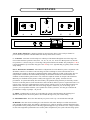
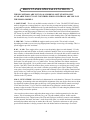
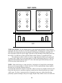
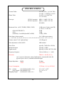
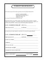
MANLEY
LABORATORIES, INC.
OWNER'S MANUAL
THE REFERENCE
PREAMPLIFIER
MANLEY LABORATORIES, INC.
13880 MAGNOLIA AVE.
CHINO, CA. 91710
TEL: (909) 627-4256
FAX: (909) 628-2482
email: [email protected]
http://www.manleylabs.com
CONTENTS
SECTION
PAGE
INTRODUCTION
3
MAINS CONNECTIONS
4
CONNECTING YOUR PREAMPLIFIER
5
REAR PANEL
6
FRONT PANEL
7
FRONT PANEL SPECIAL FUNCTIONS (SOFT-START, phono)
8
BALANCED or UNBALANCED ?
9
TOP VIEW
10
(Tube Locations, Fuses)
OPERATIONAL NOTES
11
TROUBLESHOOTING
12
SPECIFICATIONS
14
WARRANTY
15
WARRANTY REGISTRATION
16
INTRODUCTION
THANK YOU!...
for choosing the Manley Laboratories "The Reference Preamplifier". Designed by David Manley, the
Reference Preamplifier uses the best available parts with the shortest, cleanest, active signal path
possible. This Preamp is the most expensive and high quality in our range of preamps. Manley is very
highly regarded for power amplifiers and pro recording equiment but often forgotten for preamps.
Why? Simply never had a review of one. Nothing published, no ads and no USA showrooms. It is
true that essentially the same circuits have received top honors and reviews in the Reference D to A
converter and some of the professional recording products. Our complements for discovering a real
winner that the media has never even tried.
To complement our best sounding line driver to date, we used every technique to preserve
separation and audio integrity. We used a 24 position gold contact sealed Grayhill switch with metalfilm 1% 1/2 watt resistors for a superior audio attenuator. The Input Select Switches are separate as
are the mirror-image gold plated elastically suspended printed circuit boards. The RECORD output is
buffered to prevent loading. The tube regulated power supply is in a separate chassis (as you know) to
prevent noise and hum. The elegant front panel finish is a high purity plated gold that complements
the electronics both visually and in its long lasting outstanding quality.
We build two versions - one with line inputs only and the second with a unique fully
differential floating phono preamp stage. This manual is intended for both products - so if you have
the line version just skip over sections that deal with phono. Please take a few moments to read
through this manual, there may be features and information about this preamplifier which you should
familiarise yourself with.
Thank you again, and please enjoy!
GENERAL NOTES
IMPORTANT SPECIAL NOTES - READ THIS - DO THIS
The circuit boards are designed to be mechanically vibration isolated. It uses 4 elastic rings that
suspend the printed circuit boards. For shipping, the factory screws down the circuit boards to prevent
shipping damage - These need to be unscrewed. Without taking off any top or bottom perforated cover
- look at the bottom of the preamp. You should see 4 small silver colored Phillips screws. These are
towards the center and not along the edge. Remove these 4 screws ! The printed circuit will spring
up about 1/2 inch and rest. This helps prevent mechanical vibrations from affecting the sensitive
tubes. Save the screws (4-40 size). You should re-screw them (gotta open the top) for shipping
LOCATION & VENTILATION
The Reference Preamplifier must be installed in a stable location with ample ventilation. It is
recommended, if this unit is rack mounted, that you allow enough clearance on the top and bottom of
the preamp such that a constant flow of air can flow through the ventilation slots. This is especially
true for the phono version which uses 12 tubes internally. We also recommend that the preamplifier be
placed at least 10 inches away from the power amplifier(s) to reduce hum pick-up. It should also not
be placed mounted on a speaker cabinet because vibrations can shorten tube life, cause microphonics
and degrade performance. As with any electrical equipment, this preamplifier should not be used near
water or moisture. It is not designed for outdoor use.
SERVICING
The user should not attempt to service the preamplifier beyond that described in the owner's manual.
Refer all servicing other than tube replacement to Manley Laboratories.
3
MAINS CONNECTIONS
Your preamplifier has been factory set to the correct mains voltage for your country. The
voltage setting is marked on the serial badge, located on the rear panel. Check that this complies with your local supply.
Export units for certain markets have a moulded mains plug fitted to comply with local requirements. If your unit does not have a plug fitted the coloured wires should be connected to the
appropriate plug terminals in accordance with the following code.
GREEN/YELLOW
BLUE
BROWN
EARTH
NEUTRAL
LIVE
terminal
terminal
terminal
As the colours of the wires in the mains lead may not correspond with the coloured marking
identifying the terminals in your plug proceed as follows;
The wire which is coloured GREEN/YELLOW must be connected to the terminal in the plug
which is marked by the letter E or by the safety earth symbol or coloured GREEN or GREEN
and YELLOW.
The wire which is coloured BLUE must be connected to the terminal in the plug which is
marked by the letter N or coloured BLACK.
The wire which is coloured BROWN must be connected to the terminal in the plug which is
marked by the letter L or coloured RED.
DO NOT CONNECT/SWITCH ON THE MAINS SUPPLY UNTIL ALL OTHER CONNECTIONS HAVE BEEN MADE.
4
CONNECTING YOUR PREAMPLIFIER
1. Please refer to the following page for an illustration of the back of the preamplifier.
2. There are two main outputs per channel. These get connected to the power amplifier(s) when
all ON/OFF switches are off (including the amps). One pair is standard RCA unbalanced line
outputs and the other pair are balanced XLR outputs. Use either (the unbalanced RCA's are
more"purist")(The Balanced outputs have one more stage of amplification). The Balanced
outputs are the best choice to drive a second set of amplifiers in a different room. Use both
outputs for some bi-amp applications.
3. Use the RECORD OUTs to send to your tape recorder inputs. This output is derived from the
Input Select Switches. This output is buffered (another tube is used to isolate this jack) to
preserve signal integrity regardless of the load. We can recommend that one have the tape
feed plugged into the REC OUT only when actually recording especially if there are kids or
a spouse that may use the system with less respect. The main concern is selecting "TAPE"
when the tape deck is also reflecting that input and a little gain exists. If you switch to "tape"
at the preamp, when recording or if the deck is in "input" or "source" expect the howl of
feedback. Unfortunately "purist", "foolproof" and "comprehensive" are mutually exclusive.
This is normal for purist preamps that don't have a "tape monitor" switch or "record select"
switch. One eliminates extra "stuff" that might degrade the main signal path.
4. Normal line inputs are found on RCA jack inputs and can be connected to any line level
sources such as, tuners or tape decks. Each of the RCA jacks are clearly labelled as to a
typical function. Each input is for all intents functionally and electronically the same except
for the phono inputs and CD inputs. The CD inputs have 6 dB less gain because CD players
and DACs tend to have hot outputs. The phono inputs have much more gain and a frequency
response that the RIAA "curve" specifies. Connect you turntable to the moving magnet or
moving coil inputs depending on your cartridge. Don't forget to attach the turntable ground
wire to the gold ground post located between the moving magnet jacks. If you use an external
equalized phono preamp connect it to the line input of your choice.
5. There is one pair of balanced inputs with 3 pin XLR female jacks. Some newer components
allows the choice of balanced or unbalanced connection. We recommend careful listening
to determine whether the balanced or unbalanced connection is preferable. It is usually
subtle and depends on several factors. Some professional tape machines only have balanced
outputs and these would be the appropriate inputs. You may find that you want to reduce the
output level on a pro (+4dBm) tape machine to "match" your other (-10dBm) inputs.
6. Connect the two power supply cables from the power supply unit to the preamplifier.
Remember, AC power should be OFF at the power supply for for at least 5 minutes.
7. On the power supply back panel is a standard IEC mains connector. This should be connected
to a standard mains outlet with the supplied cable. This unit has been hard-wired for the
mains voltage in your country. Are you ready for music?
8. Power up the preamplifier FIRST at the POWER SUPPLY ON/OFF switch (LED glows)
and allow it to settle for a minimum of 30 seconds before powering up your amplifiers. Select
a source, turn up the volume and sit down (or dance!). Turn off your preamplifier and source
components LAST when powering down a system. (Amps on last and first off) This prevents
amplification of turn-on transients and other noises when powering up or turning a system
off and ultimately protects the speakers.
5
REAR PANEL
A
UNBALANCED
BALANCED
MOVING MAGNET
C
D
E
F
G
MAIN OUTPUTS RIGHT
A
BALANCED
AUX
AUX
CD
CD
TAPE
J
C
D
E
F
G
TAPE
TUNER
TUNER
VIDEO
VIDEO
POWER
UNBALANCED
MAIN OUTPUTS LEFT
POWER
MOVING COIL
RECORD
RECORD
H
OUT
R
H
L
BALANCED
B
OUT
BALANCED
SUPPLY
SUPPLY
I
I
B
REFER TO PAGE 5 FOR MORE EXPLANATION
A - LINE OUTPUTS - Connect these to your power amplifier inputs when the amps are off.
The XLR outputs are balanced with Pin 2 = hot or positive. Standard. See H.
B - RECORD OUTPUT - These normally are connected to the tape recorder inputs. The
signal is "picked off" before the volume control at the input selector and is isolated (buffered)
by a 12AT7WA . Be very careful. There is a possibility of feedback if someone selects "tape"
on the input selector. (or whatever the record machine returns to)
C- AUX - Plux your Aux in here - ............ Is the plural "Auxen"?
D - CD - Plug in your audio outputs from your CD player or "D to A Converter" here.
E - TAPE INPUT - Tape machine outputs can be connected here. Cassettes not allowed with a
preamp of this calibre. Just kidding. Its your system.
F - TUNER INPUT - Connect your tuner outputs here. Another good input for #2 VCR.
G - VIDEO INPUT - Audio actually, from a VCR or Laser Disc or DVD audio out.
H -BALANCED XLR - Plug an XLR cable in here - It doesn't absolutely have to be balanced but if
you do use this input for an unbalanced source, and it hums - you may need to attach a ground
wire from the source to the preamp or connect a jumper from pin 1 to pin 3.
Pin 1 = Ground (chassis),
Pin 2 = hot or +,
Pin 3 = negative or low.
I - POWER SUPPLY - The cables from the power supply box need to be plugged in here - as
long as the supply has been off at least 5 minutes.
J - PHONO INPUTS - Which pair to use (MC or MM) depends on the cartridge. If you have
Moving Coil you could alternatively use the 5 pin XLR. The XLR may be more convenient
and a more secure connector. The male mate should also have gold plated pins.
Pin 1= Right negative
Pin 2= Right positive
Pin 3= Ground - also that gold post is "ground".
Pin 4= Left positive
Pin 5= Left negative
6
FRONT PANEL
G
C
J
A
D
K L M N
G
I
E
B
H
A & B - INPUT SELECTS - 6 Position switches for input selection. There is one switch per channel to
preserve absolute separation. The RECORD OUT directly follows these switches.
C - VOLUME - 24 Position switch with precise 2 dB steps of attenuation throughout most of the range. The
most counter-clockwise position is mute, then , -60, -50, -46, -44, -42, -40 etc in 2 dB steps until -10, then the
next position is -6, then 0. This gives a wide range with good resolution in the middle. The preamp has 15 dB of
typical gain (Balance @ 12:00) thus unity gain is the 19th step. Left / right matching is typically within 1/10 dB
at any setting.
D & E - BALANCE CONTROLS - Individual level adjustments for each channel to preserve separation. Like
all balance controls we use them to center the image on some recordings or sources. Because these level
adjustments are actually in the negative feedback path they tend to change the "sound" of the preamp. This is a
unique feature in found in most of the Manley Preamps. As the balance controls are rotated clockwise the
feedback is reduced and the gain increases. You will need to adjust the Volume to compare sonic differences.
Musically, less feedback tends to produce a subtly more aggressive, fast, punchy and more forward
presentation. In systems that already have this tendency, the optimum setting will likely be from fully counterclockwise to the mid position. Some describe this as more laid back, mellow or passive. Experiment! There is no
right or wrong. Your taste will determine the position of these controls (or like us, maybe different settings for
different CD's or moods!). Rather than force some design dogma or fashion on you, we encourage you to
generate your own opinions and allow you to optimise the sound to your tastes. You also get to simulate the
presentation of a range of preamps - not just one.
F - MUTE - In MUTE there is silence. In "VOLUME" the volume control determines the listening level.
MUTE is mainly used to answer the phone or door without having to lose your volume setting.
G - POWER ON/OFF - This is the main and only AC power switch. Up = ON and the LED will light.
H -METER - This meter shows incoming AC Volts from the wall socket. With power on this meter should
center straight up and be stable. The stability is important. Low voltage or moderate variations should not affect
the performance of the preamp because of the fully regulated supplies. Large variations or low voltages common
in some areas might affect performance but it is likely other components in your system will start acting up first.
7
FRONT PANEL SPECIAL FUNCTIONS
THESE CONTROLS ARE NOT ON ALL MODELS. SOFT-START IS ONLY
AVAILABLE FOR 117 VOLT COUNTRIES. PHONO CONTROLS ARE ONLY ON
THE PHONO MODELS.
I - SOFT/START - This is only available on units wired for 117 volts. The SOFT/START (down)
mode is designed as a warm-up mode or a way to leave the pre-amp semi-powered so that it powers
up and stabilizes quicker. NORMAL mode is up and should always be used for listening. The SOFTSTART will certainly give much longer tube life than leaving the preamp powered in NORMAL. We
suggest that you turn the preamp off when not in use which reduces the electric bill and extends tube
life. Power it up in SOFT-START and give it 3 to 10 minutes in this mode, then up to NORMAL wait
30 seconds, then turn on the power amps. Do the reverse when shutting down. The tube filaments may
last decades this way. It is not a necessity but a way to achieve maximum tube life and stability.
J - MM / MC - You have to PULL the toggle towards you to switch. This switch is selected
depending on whether you use a moving magnet phono cartridge or a moving coil cartridge. This is a
special toggle to prevent "accidents".
K & L - 0 / 180 - These toggles allow you to reverse the polarity (phase) on each channel. "0" is the
normal position and both switches are usually switched in tandem. There are several applications of
these switches. A drum miked from the bottom, when struck will cause the skin to move towards the
mic and should cause the speaker (cone) to also move towards you. Unfortunately there are about a
hundred places in the recording/reproduction chain where this might have been reversed. For some
people and some systems the absolute polarity is a critical factor especially with reed instruments and
percussion. For most people it is a very subtle effect. You may find that a few albums sound more
natural in the 180 position. 2) It is possible to mis-connect the little connectors to the cartridge or miswire the 5 pin XLR. The 0/180 switches allow you the easiest way to verify that your wiring is good.
If lows are reduced when only one switch is 180 then you probably got it right 3) Strange as it may
seem, quite a lot of people buy expensive systems and accidently reverse one speaker connection and
end up with a very wierd bass shy system. We have even seen (heard) this in audiophile trade shows.
Flip one of the toggles to see if Murphy's Law applies to you too. It should sound best with both
switches in the "0" position.
M & N - LEVEL TRIMS - Individual level adjustments for each channel to "fine tune" for variations
in cartridges, its mounting to the arm and slight mis-alignments of the arm. It also allows one to adjust
for slight drift in phono preamp gains as tubes age. After getting the BALANCE controls set using a
CD or other line source - Use a a few LPs to determine if any gain trim is needed in the phono
preamps. Adjust as needed. The easiest way is with a very "mono" LP and setting the phantom center
image exactly between the speakers.
One can also use these trims to adjust the phono stage to have a similar apparent level to the other
sources. This is becoming more difficult every year. The old standard was that -10 dBv was the
nominal reference level. Digital sources like CDs and CD players and DACs seem to avoid standards
and lean towards "the hotter, the better". Audio from video decks is a variable and remote controllable
and totally dependent on the tape or station (the wild card). Tape decks and tuners are still a pretty
good reference but there is always pressure to have the loudest station or hottest tape. Good luck.
8
BALANCED or UNBALANCED ?
The topic of balanced inputs and outputs is relatively new and often confusing to some.
Balanced inputs and outputs are very old stuff to the professional recording business and telephone
systems. It was invented to reduce hum and interferance in systems with very long cables. Shielding is a
good thing but never perfect. Hum can still get in. Balanced cables use the shield the same as unbalanced
wires but they add a second signal wire. These two signal wires are generally driven with equal signals
but of opposite polarity. At the recieving end the input has the job of only accepting the difference of
these signals and rejecting any signal that is the same polarity. Because the 2 signals are opposite
polarity, they get amplified but because each of the two wires get the same hum and RF noise on them
the hum and RF should get cancelled. The standard connector for unbalanced hi-fi is the common RCA.
For balanced it is an XLR. These lines were first used for microphones and it was convenient to have a
female connector at one end and a male at the other to allow a number of cables to be connected together
for really long runs. Outputs are males. Some great uses are to 1) drive an amp in another room, 2) drive
a headphone amp, 3) drive the woofer amp in a biamped system., 4) drive VU meters if you have 'em.
Of course some power amps only have balanced inputs and this is the primary application and some
amps probably have better performance when you have the choice. You should evaluate this for yourself.
Is one form of cable inherantly better than the other ? Theoretically, balanced cables should be
better because hum and some RF will be cancelled. As a practical issue this may be not the primary
factor. Convenience may be. Chances are that most of your gear is not balanced. It is also likely that a
preamp designed to be optimum for balanced signals may be a little compromised for unbalanced and
vice-versa. The Reference Preamplifier is optimised for the much more common unbalanced RCA
interconnect and is slightly compromised in balanced modes. It uses ICs to perform balanced to
unbalanced conversion and then again from unbalanced to balanced. These are very high performance
parts designed expressly for audio but it is a few more parts in the chain.
Can you put unbalanced signals into the balanced inputs or the other way around? The answer is:
usually, but you need the correct adapters. You may also need a "ground wire" between the source and
preamp if you get some hum. Now, whether it is OK to "short" PIN 3 to Ground or PIN 1 or leave PIN 3
floating (unconnected) depends on the source. You probably shouldn't short PIN 3 to ground using the
balanced outputs of this preamplifier, just leave it floating. However if you need more output (6dB) short
PIN 3 to PIN 1 - you won't damage anything. It is what is normally referred to as a "transformer-like"
output. A true transformer output requires connecting PIN 3 to an input or ground.
By the way - You are probably aware that if you have the Phono Version that the phono inputs
are balanced. It will tend to reduce some forms of hum and RF. The main reason we did this is because it
improved the imaging and the soundstage. It was an experiment that worked well enough for us to look
into patenting the circuit. It also allows the easiest way to be sure you have absolute polarity intact - its
on switches. For checking - no wires to change!
We do get a number of calls asking us to recommend brands of interconnects. Tough question.
The best answer is to find a dealer with cables that can be tried out in your system. We have used
Kimber, Van den Hul, Illuminati, and Cardas with success and Audioquest and Goertz are very nice in
many systems. Each is different, has its own personality and should be choosen to complement the
system. A bright cable would likely be the wrong choice in a bright system. Perhaps a smoother, rounder
presentation will be the best overall balance unless you just plain love it scorching. We don't know of
any that cause problems with the preamp. We don't suggest spending more on interconnects than the
preamp or speakers. Some have suggested spending 20% of the budget on cables but we lean towards
10% or less - and listening rather than reading ads. We might suggest labelling them. A year from now it
might save some confusion. Saved you a call.
9
TOP VIEW
6414
12AU7WA
12AT7WA
12AT7WA
PHONO
PHONO
12AX7WA
12AX7WA
PHONO
PHONO
6072
12AT7WA
6414
12AU7WA
6072
PHONO
12AT7WA
PHONO
PREAMP
FUSES
6GF7A
6GF7A
OA2
OA2
POWER
SUPPLY
TUBE LOCATIONS - See the diagram above for the proper tube locations. Power should be
unplugged and allow the tubes to cool before handling them. Changing tubes on this preamp is a
little more tricky than most because the printed circuit boards are elastically suspended. It is
more important to allow the power supply capacitors to fully discharge when putting tubes into
the sockets. It is difficult to push or pull the board so that it shorts to a grounded jack but .....
The technique to remove a tube is to rock or wiggle the tube around as you gently pull.
To insert a tube, wiggle it in as you gently push. It is safer if the bottom panel is on - there are
stand-offs under the board that are about 1/2" above the bottom panel that should prevent the
PCB from going further than that 1/2".
FUSES - Each of the fuses are 1 amp slow-blow. Un-plug the AC mains before checking the
fuses to prevent any possiblity of a shock. One fuse is for the regulated high-voltage supplies,
the other two are for tube filaments (heaters).
A fuse that has turned black inside is a hint that a "short" occurred. Try another. If this fuse also
blows then there may be a problem requiring a technician but often the problem has a simple,
visible cause. The fuse is a protection device designed to stop power, rather than allowing
potentially expensive damage to the power supply. Replace only with the correct size and value.
10
OPERATIONAL NOTES
SWITCHING ON & OFF
The power switch is located on the center of the power supply unit. The best way to power up is
to start the unit in SOFT-START (toggle down). The Power Amps should be off. Turn ON the
POWER with the toggle next to it simply labelled ON and OFF. Wait a few minutes. Flip the
other toggle from SOFT-START to NORMAL, wait 30 seconds, now turn on the power amps.
You should probably wait another 5 minutes for the amps to warm up before listening. To turn
off - do it all in reverse. Power amps off first, wait, then SOFT-START, wait then you switch
off the preamp power. This procedure will lenghten tube life and ultimately protects your
speakers from thumps and turn on transients.
RUNNING
It is not recommended that you leave your preamplifier permanently switched on. This only
wastes electricity and tube life. Your preamplifier has both tube and solid state rectification and
reaches peak operating condition in approximately 30 minutes. This time is reduced by leaving
the preamp in SOFT-START rather than switching off completely. It is your choice as to faster
and glowing pretty or longer wait, safer and lower utility bills.
TUBE LIFE
As with all tubes, their quality degrades with age. This is due to cathode emission, a natural
process found in all tubes. We recommend that you have your preamplifier checked every 4-5
years, depending on usage. An excessive increase in noise level can indicate the need to replace
a tube. Other signs of a bad tube include excessive microphonics (found by lightly tapping on
tubes), vacuum leak (air leaked in, not the vacuum leaked out)(usually the tube looks white
inside) or the filament (heater) burnt out (cold, dark tube). SOFT-START reduces the thermal
shock experienced by the filaments. Ever notice how most of the time a light bulb dies it is right
when you turn it on? A cold filament draws much more current initially, then as it comes up to
operating temperature, the filament's resistance rises and the needed current is much less. Some
users report tube life of 30 years without SOFT-START however there is no way to predict the
life of one tube. SOFT-START will protect against most premature tube death.
HUM This unit is meant to use the third pin of the mains as the ground reference. Many power
amps also use the third pin mains ground. Here we have a potential source of hum and what we
call ground loops. The solution is to use ONE of those grounds and only one. Use an 3 pin to 2
pin adapter (if it is legal in you country) for some equipment rather than breaking off the ground
pins. Typically one power amp will be grounded and all other 3 pin mains gear will have
adapters. Sometimes the better option is to ground the preamp and "float" the amps. Another
ground loop type is caused with Cable TV. If removing the cable cleans up the system you can
get good quality CATV isolation transformers. Problem gone and the picture may improve
because noise is removed from that signal too. Don't panic, experiment.
One source of hum can be equipment stacked on top of one another. This is not a good
plan from the ventilation standpoint generally, and it is known to introduce hum, buzz or noise
into the system. Certain gear radiates magnetic fields or high frequency noise around its chassis
and other gear may be prone to receiving these fields. A little distance helps greatly.
11
TROUBLESHOOTING
GENERAL TROUBLESHOOTING
We don't presume you are expert with a sodering iron or that this is your first audio system. This section is for all
and is simply meant to help with a variety of audio problems and some not specific to your preamp.
It is easier to find a problem in a stereo system than a mono system even though there is twice as much electronics
and wires. When you have two channels, there is some built in redundancy that can make fast work of finding a
problem. This is how we teach newcomers to repair 64 channel recording consoles - you have 63 good channels,
use one of them to compare to the bad channel to locate exactly where the problem lives. A little swapping and
bingo -it must be this. A little detective work is advised before you jump on the phone. For example if the left
channel is distorted, you might swap the left and right outputs of the preamp. If the distortion is still in the left
channel, then it must be after the preamp. That means it has to be the amp or the speakers (this logic is easy). The
next step would be to return the preamp connections back to normal, to keep things straight and then swap left and
right power amp outputs (feeding the speakers). If the distortion changed sides or followed the swap then the
distortion is before that point which pretty much indicates the amp is the bad boy. If the distortion is still on the left
side then you can bet the speaker needs work. The idea here is that you can start somewhere in the middle of the
"chain" and follow the problem up or down pretty quickly and with a good deal of "proof". The only rule is that if
the problem follows the swap, then it is before that point and if it stays in the same side then it is after that point.
Educated guesses can help give a starting point and this swapping method gives some certainty. This works
whenever one side is strange. Tube gear is often very easy to "fix" by simply repacing a tube. Remember when
even your parents could fix the TV set by taking a bag of tubes to the corner store tube tester? You are allowed to
swap tubes from one channel to the other (as long as it is the same number) You might want to look at the diagram
on page 9 to see tube locations and the easiest method to pull them. Again educated guesses might help. Would you
like a few examples of educated guesses?
NOISE or HISS. The smaller the signal, the more gain is needed and the more likely it will cause hiss. In the case
of a preamp, the first phono stage deals with the smallest signal. That would be one of the 6072's. It may not be the
6072 but that would be the first guess. You can always switch to, for example AUX, to verify that the hiss is only
when you are switched to PHONO. If it wasn't the 6072, there is a 12AX7 right after it that could be swapped with
the 12AX7 from the other side. Let's imagine that, the hiss has been traced to the preamp but that its on the right
side on every input (CD, phono, AUX, etc). That eliminates the phono tubes and sort of suggests that it might be
the first preamp tube (smallest signal) which would be the right side's 12AU7. The 12AT7 in front of it is used to
drive the RECORD OUT. The last guess would be the final tube, the 6414.
DISTORTION. Here the educated guess would start off with the speaker - only because statistically, speakers are
most often the culprit, then the power amps would be the second bet. Probably the preamp would be the least
likely. As a matter of fact, it is more likely to be a shorted interconnect. If it does seem to be the preamp, once
again a few tube swaps will narrow it down to one tube usually.
HUM. We pointed out a few common sources of hum on the previous page - you might want to try those first.
Here is an interesting technique. Use the preamp to help locate the hum. First (no music) we would turn down the
VOLUME, if the hum also drops then it is almost certainly before the preamp. With the volume up again, switch
the INPUT SELECT. It should show if one source is the cause. At the other end, you could disconnect the inputs to
the power amps and see (hear) if the hum goes away. If it doesn't then we would tell you it has to be the power amp
especially when only one channel hums. The "real" way to do this is to use a shorting connector instead of having a
jack open with no connection. We use old cheap RCA interconnects cut to about 2 inches long with the shield and
center conductor connected together. This eliminates any hum caused by unconnected hi impedance connectors.
The shorting connector simulates the perfect source - low impedance and very quiet. If the hum seems everywhere
- the best method might be to start from scratch. disconnect all the sources and plug them in one at a time until you
get hum. This should point at some piece of gear. It might actually be pointing at two if there is a ground loop.
Check for 3 pin AC plugs. You should only have one AC plug ground pin in use. The others get "lifted" (if that is
legal in your country).
12
DEAD CHANNEL or BOTH CHANNELS SILENT. One channel dead should be easy if you follow the channel
swapping technique. If it is the preamp, then go the next step and swap tubes. What is the most common repair
technique? - wiggle or re-seat the interconnects. Often it's that easy to find a bad connection. A very technical version
of this is used to troubleshoot intermittant gear. Open it up and tap around with a plastic pen. Some part, connection
or area of the circuit will usually be the worst. Next step - a close visual inspection - most of the time you can see
the problem - but you might need a soldering iron to fix it. What if both channels are dead? Can't swap. Have you
checked the fuses? Possibly that easy. You can still use the process of elimination most of the time. You might be
able to verify that the problem is or isn't the preamp. Some gear also has volume controls, and these could be carefully
plugged into the power amp. See if this works. Here is a common technique used by most techies. Unplug the
interconnect from a source (preamp, CD, whatever) and while holding the RCA shell in the same hand, gingerly touch
the center pin. It should hum. This "technique" should be accompanied with a few warnings, like try to prevent outof control loud hum. If you turn down the amps you may save your speakers. While we are here, the one handed
technique is the safest way to work on tube gear. You don't want the other hand resting on a metal surface. This way
if you get a shock, it is only through the hand and not through the chest or body. Remember, all electronic gear tends
to hold a charge after power is removed because there are capacitors in there whose function is to hold a charge. The
only difference with tube gear is that the voltages are higher which means that you will feel it enough to remember
it a long time. This is the big reason why you should really wait a while after the gear is turned off to let these capacitors
discharge. Also note that there may be some caps that don't have quick discharge paths - so use one hand and/or rubber
gloves when the circuit is exposed. Avoid touching metal bits like component leads, printed circuit traces as well as
heat sinks and big resistors (they might be thermally hot or electrically hot).
CIRCUIT MODS. Many people think that every piece of gear can be improved by changing a few capacitors or
resistors or wires. Some techs make a living by promoting that fear/belief. Sometimes this is true - particularly with
cheap gear or gear designed by inexperienced audio buffs or hobbiests. We have never known of any mod to Manley
equipment that was a real benefit (not imaginary) or cost effective. If there was, not only would it already be in the
gear but we would have been the first to think of it. Here is the big scary downside - the long and generous warranty
will be completley invalid and if the gear ever has to be repaired by the factory then the first job will be to return the
unit to "stock" and the second job will be writing an invoice for that effort. The only possibly interesting upgrade might
be to try other tubes. It must be the same generic number and a tube in superb condition. If one is lucky they may have
a marginally better tube but they would be very lucky to have two or more of them. We use the very best tubes available
(in quantity) and not those overhyped and overinflated in price. We also know that most of the time it is a wasted effort
that may only be considered compensation for flaws in other parts of the system. Do two wrongs make a right? One
exception is our use of 300B's. We use very good tubes that allow the product to be sold for a fair price to you. If we
built the amp with $300 - $600 tubes it would be out of many people's range. This is the only exception and if cost
is no object then go for it. You can order any of our 300B products with the tube of your choice or our recommendation
if you don't mind the added cost. The Reference Preamp is not one of these - no 300Bs and it uses the best available
selected tubes along with the best of NOS JAN tubes in the most critical positions. Unlikely, anybody can "improve"
on this. If a tube does fail, the best plan is to order one from Manley, so that it most matches the other side and the
circuit in general. That brings up a little point. Some people rant on about certain tubes being this or that. It is usually
the result of having tried something once and it worked or didn't. The real deal is that, each tube and sometimes
different versions can only be reasonably be judged within the circuit it was properly designed for. A different circuit,
and all bets are off. A silly design may get best results with a silly tube. In real-world engineering almost every change
will improve some aspect a little and have a bigger negative effect somewhere else (probably where you weren't
looking). It is all too easy to jump to conclusions - especially with subtle differences. Check & re-check.
MAJOR UPGRADES. The biggest and most overlooked improvement to most audiophile systems is the acoustics.
A large proportion of audiophile systems and even recording studios are candidates. It is very often the reason when
known great gear gives a somehow less than enthralling reproduction. Unfortunately it is a deep subject with as much
misconceptions, BS and marketting hype as any other audio topic. The costs range from very little to major
consideration to wow. We suggest reading books on home recording studio construction and/or hiring a reputable
acoustics consultant for an afternoon if you question your room. This shouldn't stop you from rearranging your
furniture, listening and evaluating. Large flat hard surfaces like walls should be broken up - bookcases are a great
wall treatment offering diffusion and absorbsion. Often some absorbsion in the corners or the wall behind the speakers
cleans up tubby bass. Play with speaker positioning even to the point of moving the system 90 degrees in the room.
Experiment - You should know if it is better and it didn't cost much to try, besides its a good work-out.
13
SPECIFICATIONS
Vacuum Tubes:
2 x 12AT7WA, 2 x 12AU7WA
2 x 6414, 2 x 6GF7A, 2 x OA2
2 x 6072, 2 x 12AX7WA
2 x 12AT7WA,
Phono Tubes
Fuse type
120VAC operation:
220VAC operation:
Maximum Gain (AUX, TUNER, VIDEO, TAPE)
(BALANCED INPUT)
(CD)
(PHONO) ( if available)(both MC & MM)
Gain Steps (volume control)
MDL1, 1 AMP / 250 Volt
MDL1, 1 AMP / 250 Volt
SLO-BLO
19 dB at max Volume (min FB)
(1 volt in = 5 volts out)
20 dB
13 dB
55 dB @ 1KHz
24 x 2 dB except extremes
(-∞,-60,-50,-46, -44,-42,-40,-38,-36,-34, -32,-30,-28,-26,-24,-22,-20,-18,-16 -14,-12,-10, -6, 0)
Volume control "Left / right tracking"
1/10 dB typical
Gain adjustment via BALANCE
8 dB nominal
Noise Floor
Maximum output
Signal to noise
typically -70 dB (20 to 30 kHz)
typically +30 dBv
typically 105 dB A WGT 20-20K
Frequency Response
5 Hz to 90 kHz @ +/- .6 dB
Distortion
THD+N = -80 dB (.01 %)
zero "crossover" distortion, mostly 2nd harmonic, unmeasurable after 5th
typical of pure Class A1, minimal feedback designs.
Output Impedance
MAIN
TAPE
30 ohms
1000 ohms
Power Consumption
170 Watts (1.4 A @ 120VAC)
Size
19" x 11.5" x 5.25"
19" x 10" x 2.5"
38 lbs
preamp
(not including handles, feet)
power supply (not including, feet)
Shipping Weight
(includes box, cables, etc.)
14
WARRANTY
All Manley Laboratories equipment is covered by a limited warranty against defects in materials
and workmanship for a period of 90 days from date of purchase to the original purchaser only. A
further optional limited 5 year warranty is available to the original purchaser upon proper
registration of ownership within 30 days of date of first purchase.
Proper registration is made by filling out and returning to the factory the warranty card attached to
this general warranty statement, along with a copy of the original sales receipt as proof of the
original date of purchase. Only 1 card is issued with each unit, and the serial number is already
recorded on it.
If the warranty registration card has already been removed then this is not a new unit, and is
therefore not warranted by the factory. If you believe this to be a new unit then please contact the
factory with the details of purchase.
This warranty is provided by the dealer where the unit was purchased, and by Manley Laboratories,
Inc. Under the terms of the warranty defective parts will be repaired or replaced without charge,
excepting the cost of tubes. No warranty is offered on tubes, unless:
1. a Manley Laboratories preamplifier is used with a Manley Laboratories amplifier, and
2. the warranty registration card is filled out.
In such a case a 6 month warranty on tubes is available with the correct recording of the serial
number of the preamplifier on your warranty registration card.
If a Manley Laboratories product fails to meet the above warranty, then the purchaser's sole
remedy shall be to return the product to Manley Laboratories, where the defect will be repaired
without charge for parts and labour. The product will then be returned via prepaid, insured freight,
method and carrier to be determined solely by Manley Laboratories. All returns to the factory must
be in the original packing, (new packing will be supplied for no charge if needed), accompanied by
a written description of the defect, and must be shipped to Manley Laboratories via insured freight
at the customer's own expense. Charges for unauthorized service and transportation costs are not
reimbursable under this warranty, and all warrantees, express or implied, become null and void
where the product has been damaged by misuse, accident, neglect, modification, tampering or
unauthorized alteration by anyone other than Manley Laboratories.
The warrantor assumes no liability for property damage or any other incidental or consequental
damage whatsoever which may result from failure of this product. Any and all warrantees of
merchantability and fitness implied by law are limited to the duration of the expressed warranty.
All warrantees apply only to Manley Laboratories products purchased and used in the USA.
Some states do not allow limitations on how long an implied warranty lasts, so the above
limitations may not apply to you. Some states do not allow the exclusion or limitation of incidental
or consequential damges, so the above exclusion may not apply to you.
This warranty gives you specific legal rights and you may also have other rights which vary from
state to state.
WARRANTY REGISTRATION
We ask that you please fill out this registration form and send the bottom half to:
MANLEY LABORATORIES
REGISTRATION DEPARTMENT
13880 MAGNOLIA AVE.
CHINO CA, 91710
Or you may FAX this form in to: 909-628-2482
Registration entitles you to product support, full warranty benefits, and notice of product
enhancements and upgrades. You MUST complete and return the following to validate your
warranty and registration. Thank you again for choosing Manley Laboratories.
MODEL REFERENCE PREAMP SERIAL No.__________________
PURCHASE DATE ______________ SUPPLIER ______________________
-------------------------------------------------------------------------------------------------------PLEASE DETACH THIS PORTION AND SEND IT TO MANLEY LABORATORIES
MODEL REFERENCE PREAMP SERIAL No.___________________
PURCHASE DATE ______________ SUPPLIER _______________________
NAME OF OWNER _______________________________________________
ADDRESS ______________________________________________________
CITY, STATE, ZIP ________________________________________________
TELEPHONE NUMBER ___________________________________________
COMMENTS OR SUGGESTIONS?__________________________________
PHONO CARTRIDGE?
SOFT-START?