1
Owner's Manual
iP
R
0
FE
S
S
I
0
NAL_
3/8 in. PROFESSIONAL
ELECTRIC DRILL
Variable Speed / Reversible
Double Insulated
Model No.
315.269460
Ryobi
Save this manual for
future reference.
_,
• Safety
• Features
CAUTION:
Read and follow
all Safety Rules and Operating
Instructions before first use of
this product.
• Operation
• Maintenance
• Parts List
Customer Help Line: 1-800-932-3188
Sears, Roebuck and Co., 3333 Beverly Rd., Hoffman
Visit the Craftsman web page: www.sears.com/craftsman
972000-957
12-01
Estates,
IL 60179
USA
•
Tableof Contents .....................................................................................................................................................
•
General Safety Rules ............................................................................................................................................
•
SpecificSafety Rules ...............................................................................................................................................
4
•
•
Symbols....................................................................................................................................................................
Features ...................................................................................................................................................................
5
6
•
Operation.............................................................................................................................................................
•
Maintenance ...........................................................................................................................................................
11
•
Accessories ............................................................................................................................................................
12
•
Warranty .................................................................................................................................................................
12
•
ExplodedView and Repair Parts List.....................................................................................................................
13
•
Parts Ordedng/Service .........................................................................................................................................
14
WARNING: Read and undendand all
instructions. Failure to follow all instructions
listed below may result in electdc shock,fire,
and/or serious personal injury.
SAVE THESE INSTRUCTIONS
•
Do not operate powertools in explosive atmo.
spheres, such as in the pmserme of flammable
liquids, gases, or dust. Power tcols create sparks
which may ignite the dust or fumes.
•
Keep bystandem, children, and viaitom away
while operating a power tool. Distractionscan
cause you to lose control.
Personal Safety
•
Stay alert, watch what you are doing, and use
common sense when operating a power tool, Do
not use tool while tired or under the influence of
dnJgs, alcohol, or medication. A moment of
inattentionwhile operating power tools may resultin
serious pamor,_l injury.
•
Dines properly. Do not wear loose clothing or
jewehy. Contain long hair. Keep your hair,
clothing, and gloves away from moving parts.
Looseclothes, jewelry, or long hair can be caughtin
moving parts.
•
Avoid accidental starting. Be sure switch is off
before plugging in. Carrying toolswith your finger
on the switchor pluggingin tools that have the
switah on invitesaccidents.
•
Remove adjusting keys orwranchee before
turning the tool on. A wrench or a kay that is left
attached to a rotatingpad: oftha tool may resultin
personalinjury.
Do not ovanmech. Keep proper footing and
balance at all times. Pmper footing and balance
enables better control of the tool in unexpected
situations.
Electrical Safety
•
•
•
•
7-10
When operating a power tool outside, usa an
outdoor extension cord marked "W-A" or "W,"
These cordsam rated for outdoor use and reduce
the riskof electricshock.
Work Area
Keep your work area dean and well lit. Cluttered
benchesand dark areas inviteaccidents.
2-3
Keep cord away from heat, oil, shal_ edges, or
moving parts. Replace damaged cords immediately. Damaged cords increase the risk of electric
shock.
A
•
2
Double insulated tools are equipped with a
poladzad plug (one blade is wider than the
other). This plug will fit in a polarized outlet only
one way. If the plug does not fit fully in the
outlet, mvaree the plug. If it still does not fit,
conlaet a qualified electrician to install • polarizad outlet. Do not change the plug in any way.
Double insulation[] eliminatesthe need forthe
three-wire grounded powercord and grounded
power supply system.
Avoid body contact with grounded surfaces,
such as pipes, rediatore, ranges, and mfdgeratom. Them is an increased riskof electricshock if
your body is grounded.
•
Don't expose powartools to rein or wet conditions, Water enteringa powertool will increasethe
risk of electric shock.
•
Do not abuse the cord, Never use the cord to
carry the tools or pull the plug from an outlet,
2
Use safety equipment. Always wear eye protection. Dust mask, nonskidsafety shoes, hard hat, or
hearing protectionmust be used for appropriate
conditions.
Tool Use and Care
•
Use clamps or other practical way to secure and
support the workpiece to a stable platform.
Holding the work by hand or againstyour body is
unstable and may loadto loss of control.
•
Do not force tool. Use the correct tool for your
application. The correcttool will do the job better
and safer at the rate for which it is designed.
Do not use tool if switch does not tom it on or
off. Any tool that cannot be controlledwith the
switch is dangerous and must be repaired.
•
•
•
•
Check for misalignment or binding of moving
pads, breakage of parts, and any other condition
that may affect the tool's operation. If damaged,
have the tool serviced before using. Many
accidents are caused by poorly maintained tools.
•
Use only accessodse that are recommended
by
the manufacturer for your model. Accessories that
may be suitable for one tool may become hazardous
when used on anotber tool,
Service
•
Disconnect the plug from the power source
before making any adjustment=, changing
acoeseodse, or storing the tool. Such preventive
safety measures reduce the risk of starting the tool
accidentally.
Store idle tools out of the reach of children and
other untrained psmons. Toolsare dangerous in
the handsof untraineduSerS.
•
Maintain tools with care. Keep cutting tools
sharp and clean. Properly maintainedtools with
sharp cuttingedges are less likelyto bind and are
easier to control.
3
Tool sewine must be pedonmed only by qualified
repair personnel. Service or maintenance performed by unqualifiedpersonnel could resultin a dsk
of injury.
When servicing a tool, use only identical replacement pads. Follow instructions in the
Maintenance section of this manual. Use of
unauthorizedparts or failure to follow Maintenance
Instructionsmay create a risk of eleotdcshock or
injury.
Hold tool by insulated gripping surfaces when perfomning an operation where the cutting tool may contact
hidden wiring or its cord. Contact with a "live" wire will make exposed metal parts of the tool "five" and shock the
operator.
Additional Rules for Safe Operation
•
Know your power tool. Reed operator's manuel
carefully. Learn its applications end limitations, as
well as the specific potential hazards related to
this tool, Following this rule will reduce the risk of
electric shock,tim, or sedous injury.
•
Always wear safoty glasses. Everyday ayeglaeses
have only impact.rcaistant lenses; they are NOT
safety glasses. Followingthis rulewill reducethe risk
of serious personal Injury.
•
Protect your lungs, Wear a face or duat mask if the
operation is dusty. Followingthis nJtewill reducethe
risk of serious personal injury,
•
Protect your hearing. Wear hcadeg protection
dudng extended periods of operation, Following
this rule will reducethe risk of seriouspersonal injury.
•
Inspect tool cords pedodicelly and, if damaged,
have repaired at your nearest Factory Service
Center or other Authorized Service Organization. Constantly stay aware of cord location.
Followingthis rule will reduce the risk of electric
shock or fire.
•
•
Check damaged perle. Before furlher usa of the
tool, a guard or other pad that is damaged
should be carefully checked to determine that it
will operate propedy and perform its intended
function. Check for alignment of moving pelts,
binding of moving peas, breakage of parts,
mounting, and any other conditions that may
affect its operation, A guard or other pelt that is
damaged should he properly repaired or replaced
by an authorized service center. Followingthis
rule will reduce the dsk of electdc shock,fire, or
serious injury.
Don't abuse cord. Never cam] the tool by the
cord or yank it to disconnect it from the receptacle. Keep cord away from heat, oil, and sharp
edges. Followingthis rule will reduce the risk of
electric shock or fire.
•
Make sure your extension cord is in good
condition. When using an extension cord, be
sure to use one heavy enough to cam] the
currant your product will drew. A wire gage size
(A.W.G.) of at least 16 is recommended for an
extension cord 100 feet or less in length. A cord
exceeding 100 feet is not racommended. If in
doubt, use the next heavier gage. The smaller
the gage number, the heavier the cord. An
undersizedcord will cause a drop in linevoltage
resulting in loss of power and overheating.
•
Inspect for and remove all nails from lumber before drilling. Followingthis rule willreducethe riskof
serious personal injury,
•
Drugs, alcohol, medication. Do not operate tool
while under the influence of drugs, alcohol, orany
medication. Followingthis rule will reducethe risk of
electdc shock,fire, or serious personal injury.
•
Save these instructions. Refer to them frequently
and use them to instruct others who may use this
tool. If you loan someone this tool, loan them
these instructions also.
A
WARNING: Some dust created by power
sanding, sawing, grinding, drilling, and other
construction activities contains chemicals known
to cause cancer, birth defects or other
reproductive harm. Some examples of these
chemicals are:
lead from lead-based paints,
crystalline silica from bricks and cement and
other masonry products, and
• arsenic end chromium from chemicallytreated lumber.
Your risk from these exposures varies,
depending on how oftenyou do this typeof work.
TO reduce your exposure to these chemicals:
work in a well ventilated area, and work with
approved safety equipment, such as those dust
masks that are specially designed to filter out
microscopic particles,
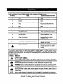
Important:
Someofthe following
symbolsmay be used on yourtool. Please studythem and leam their meaning.
Proper interpretationof these symbols will allow you to operate the tool better and safer.
SYMBOL
NAME
DESIG NATIONIEXPLANATION
V
Volts
Voltage
A
Amperes
Current
Hz
Hertz
Frequency (cyclesper second)
W
Watt
Power
Minutes
Time
Atterna'dng Current
Type or a characteristicof current
no
No Load Speed
Rotational speed, at no load
[]
Class II Construction
Designates Double Insulated
Constructiontools
Revolutionsor Rec'lprocetlonPer Minute
Revotutions,strokes,surface speed,
orbits etc. per minute
Safety Alert Symbol
Indicatesdanger, warningor saution.
It means attentionll! Your safety is
involved.
min
..Jmin
,_k
The purpose of safety symbols is to attract your attention to possible dangers. The safety symbols, and the
explanations with them, deserve your careful attention and understanding. The safety warnings do not by
themselves eliminate any danger. The instructionsor warningsthey give are not substitutesfor properaccident
)raventionmeasures.
SYMBOL
MEANING
_k
SAFETY' ALERT SYMBOL:
Indicatesdanger,warning,or caution.May be used in conjunctionwith othersymbols or pick)graphs.
,_
DANGER:
Failurete
obey a sefaty
warningwinrssultin
sedous shockand
injurytoyourselforto
others.Always
follow
the safety
precautionsto
reducethe
dsk of fire, alectdc
personal injury.
,_
WARNING:
to obey
a safety warning
can risk
result
in sadous
injuryto
yourseffor
others.
Always followFailure
the safety
precautionsto
reducethe
of fire,
electdc
shock and
personaltoinjury.
i_
CAUTION: Failure to obey a safety warning may result in pmpertydamage or personal injuryto
yourself or to others, Alw_s follow the safety presautions to red_e the risk of fira,electdc shock and
personal injury.
NOTE:
Advises you of informationor instructionsvital to the operationor maintenance of the equipment.
SAVE THESE INSTRUCTIONS
5
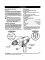
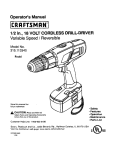
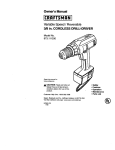
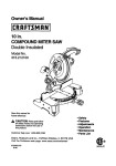
KNOWYOURELECTRICDRILL
APPLICATIONS
See Figure 1.
(Use only for the purpose listed below)
• Drillingin wood.
Before attempting to use your drill, familiarize yourself
with all operatingfeatures and safety requirements.
Your drillhas many features for making drillingoperations more pleasant and enjoyable. Safety, performance, and dependability have been giventop priority
in the design of this drill making it easy to maintain and
operate.
A
CAUTION: Carefully read through this entire
owner's manual before using your new ddll. Pay
close attentionto the Rules For Safe Operation,
Warnings, and Cautions. If you use your drill
pmpedy and only for what it is intended,you will
enjoy years of safe, reliableservice.
ELECTRICAL
CONNECTION
•
Drillingin ceramics, plastics,fiberglass, and laminates.
•
•
Drillingin bothhard and soR metals.
Using driving accessories, such as driving screws
with screwdriverbits.
•
Mixingpaints.
PRODUCT SPECIFICATIONS
Chuck Capacity .................................... 1/16 in,to 3/8 in.
Horsepower................................................................ t/2
Input ............................................... 120 Volts,AC, 60 Hz
Rating.......................................................... 6.0 Amperes
No Load Speed ........................................... 0-2500 RPM
Your drill has a precisionbuilt electdc motor. It should
ha connected to a power supply that is 120 volts, 60
Hz, AC only (normal household curt'ant). Do not
operate this tool on direct current (DC). A substantial
voltage drop will cause a loss of power and the motor
will overheat. If your drill does not operate when
plugged intoan outlet, double-check the power supply.
TOPVIEWOFLEVEL
FORHORIZONTAL
DRILUNG
Nd_Weight .......................................................... 4.5 Ibs.
LEVEL
A convenientfeature providedon your drillis the level.
The level is recessed in the motor housingand can he
used to keep drill bits level during both horizontaland
vertical ddllingoperations.
ENDVIEWOF LEVEL
FORVER11CAL
DRlUJNG
FORWARD-REVERSE
LEVER
KEYLESSCHUCK
SWITCH
TRIGGER
LOCK-ON
BUTTON
Fig. 1
WARNING: Do not allow familiarity with tools to make you careless. Remember that a careless fraction
of a second is sufficient to Inflict severe injury.
6
_l
WARNING: If any pars are missing, do not
operate this tool untilthe missing parts am
replaced. Failure to do so could result in possible
serious personal injunj.
WARNING: Always wear safety goggles or safety
glasses with side shields when operating your drill.
Failure to do so could result in duct, shavings,
loose particles or foreign objectsbeing thrown into
your eyes, causing possiblesedous injury,
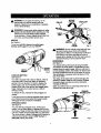
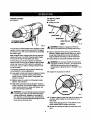
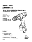
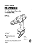
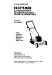
SWITCH
See Figure 2.
DRILLBIT
RELEASE
(UNLOCK)
CHUCKBODY
CHUCK
JAWS
GRIP
(TIGHTEN)
CHUCK
COLLAR
To turn your drillON, depress the switchtrigger.
Release switch trigger to turn your ddll OFF.
Fig. 3
WARNING: Do not hold the chuck bodywith one
hand and use the power of the drillto tighten
chuck jaws on ddll bit,The chuck bodycould slip in
your hand or your hand could slipand come in
contact with a rotatingdrill bit.This could cause an
accident resulting in sedouspersonal injury.
LOCK-ON
BuI"rON
TmGGER
Fig. 2
LOCK-ON BUTTON
See Figure 2.
Your drill is equipped with a lock-onfeature, which is
convenientwhen continuousdrillingfor extended
periodsof time is required,To lock-on,depress the
switchtdgger, push in and hold the lock-on button
located on the side of the handle, then release switch
trigger. Release lock-on button and your ddll will
continue running.
To release the lock,depress the switch tdgger and
release.
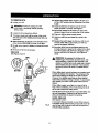
REVERSIBLE
See Figure 4.
Your elsotdc ddll hasthe feature of being reversible,
The directionof chuck rotationis controlled by a lever
locatedabove the switch trigger. With your drillheld in
normaloperating position,the directionof rotationlever
shouldbe positioned to the left of the switch for ddlling,
The ddll directionis reversed when the lever is to the
rightof the switch.
The design of the switch will nat permit changing the
directionof rotationwhile the ddll is running, Release
the switch trigger and allow the drillto stop before
changing its direction.
Note: Your ddll will not run unlessthe switch lever is
pushedfullyto the left or right.
FORWAP_
REVERSE REVERSELEVER
If you have the lock-onfeature engaged dudng usa and
your drill becomes disconnectedfrom power supply,
disengage the lock-onfeature immediately.
KEYLESS CHUCK
See Figure 3
Your new drillhas a keyless chuck, As the name
implies,you can hand tighten or release drillbit in the
chuck jaws. Grasp and hold the collar of the chuck with
one hand. Rotate the chuck body with your other hand,
The arrows shown in figure 3 indicatewhich directionto
rotate the chuck body in order to GRIP (tighten) or
RELEASE (unlock) the drill bit.
FORWARD
Fig. 4
VARIABLESPEED
TO INSTALL BITS
See Figure 6.
See Figure 5.
•
Unplugyour drill,
DRILL•T
CHUCKJAW$
CHUCKBODY
CHUCKCOLLAR
PULLSWITCHTRIGGER
RIGHT
Fig. 6
Fig. 5
_
Your ddfl has a variable speed switch designed to allow
operatorcontrol of speed and torque limits. The speed
and torque of your drill can be increased by depressing
the switchtdgger.
Note: Depress switch tdgger all the way for maximum
speed and torque of your ddll. Depress switchtdgger
only pad:of the way for less speed and torque.
Avoid runningyour drill at low speeds for extended
periodsof time, Running at low speeds under constant
usage may cause your ddll to become overheated. If
this occurs, cool your ddll by running itwithout a load
and at full speed.
The following guidelines may be used in determining
correct speed for various applications;
WARNING: Failure to unplugyour ddll could
result In accidental starting causing sedousinjury.
•
Open or close the chuck jaws to a point where the
opening is slightlylarger than the ddll bit you intend
to use, Also, raise the front of your ddll slightlyto
keep the drill bitfrom falling out of the chuck jaws.
BI Insert ddll bit intochuck the full length of the jaws,
A
•
WARNING: Do not insert drill bit intochuck jaws
and tighten as shown in figure 7. This could cause
drillbit to be thrown from your drill resulting in
possibleserious personal injuryor damage to your
chuck.
Tighten the chuck jaws on drill bit.
III Low speed is ideal when minimum speed and power
is required. For example: starting holes without
center punching, ddving screws, mixing paint, and
drilling in ceramics.
•
•ediuro speed is suitable for ddllinghard metals,
plastics,and laminates.
•
High speed produces best results when maximum
power is required. For example: ddlling in wood, soft
metals such as aluminum, brass, and copper, and
when using drivingaccossodes.
WARNING: Your ddll should never be connected
to power supplywhen you are assembling parts,
making adjustments, installingor removingddll
bits, cleaning, orwhen not in use. Disconnecting
your drillwill prevent accidental starting that could
cause serious personal injury,
Fig. 7
•
To tighten: grasp and hold the collar of the chuck with
one hand, while rotatingthe chuck body with your
other hand.
Note: Rotate the chuck body in the directionof the
arrow marked GRIP to tighten chuck jaws.
•
Do not use a wrench to tighten or loosen the chuck
jaws.
TO REMOVE BITS
•
_k
•
Unplug your drill.
•
WARNING: Failure to unplug your drill
could result in accidental staring causing
serious injury,
•
•
Loosen the chuck jews from ddll bit,
•
To loosen: grasp and held the collar of the chuck
with one hand, while rotatingchuck bodywith your
other hand.
•
Note: Rotate the chuck body in the directionof the
arrow marked RELEASE to loosen chuck jaws.
Do not use a wrench to tighten or loosen the chuck
jaws.
•
Depress and release switch triggerto be sure your
drillis in OFF positionbefore connecting it to power
supply.
Check the direction of rotationlever for correct
setting(forward or reverse). See F_gure4.
Secure the material to be drilled in a vise or with
clamps to keep it from turning as the drillbit rotates,
•
Plug your ddli into power supplysource,
•
Hold your drillfirmly and place bit at pointto be
ddlled.
•
Depress the switchtrigger to start your drill. Do not
Iocktha switch ON for jobs where your ddll may
need to be stopped suddenly.
• Move the drillbit into the workplace applying only
enough pressure to keep the bit cutting. Do not force
your drillor apply side pressure to elongate a hole.
Let your ddll and bit do the work. SeeF/gures8
and 9.
• Remove drillbit from chuck jaws,
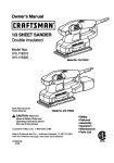
DRILLING
See Figures 8 and 9.
LEVEL
_k
WARNING: Be prepared for bindingor bit
breakthrough,When these situationsoccur, drill
has a tendency to grab and kick oppositeto the
directionof rotationand could cause loss of control
when breakingthrough materials. If not prepered,
this loss of controlcan result in possible serious
injury.
ENDVIEW
When drillinghard, smooth surfaces use a canter punch
to mark the desired hole location. This will preventthe
drill bitfrom slippingoff center as the hole Is started.
However, the variable speed feature allows starting
holes withoutcenter punchingif desired. To accomplish
this, operate your drill at a low speed untilthe hole is
started.
When drillingmetals usa a light oil on the drill bit to
keep itfrom overheating. The oil will prolongthe life of
the bit and increase the drillingaction,
If the bit jams in the work piece or if yourdrill stalls, stop
the tool immediately,Remove the bit from the work
piece and determine the reason for jamming.
LEVEL DRILLING
See Figures 8 and 9.
Fig. 8
9
A convenientfeature provided on your drill is a level, It
is recessed in the motor housingon your drill. It can be
used to keep ddll bits level during both horizontaland
vertical ddllingoperations,
TOP VIEW
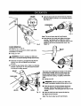
•
Open the chuckjaws and remove hex key. Remove
the chuck screw bytuming it in a clockwise direction.
Se_ Figure 11.
SCREWDRIVER
LEVEL
Fig. 11
Note: The chuck screw has left hand threads.
•
Insert hex key intochuck and tighten chuck jaws
securely, Tap sharply with a mallet in a counterclockwisedirection.This will loosen the chuck on the
spindle. It can now be unscrewed by hand. See
Figure 12.
Fig. 9
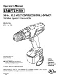
CHUCK REMOVAL
See RgureS 10, 11, and 12.
The chuck must be removed in order to use some
accessories. To remove:
•
Unplug your drill.
A
WARNING: Failure to unplugyour ddll could
result in accidental starting causing serious Injury.
•
Insert a 8 mm (5/16 in.) or larger hex key intothe
chuck of your drilland tighten the chuckjaws
securely.
Tap the hex key sharply with a mallet in a clockwise
direction. See Figure t0. This will loosenthe screw
in the chuck for easy removal.
•
Fig. 12
MALLET
The chuck may at times become loose on the spindle
and develop a wobble. Also, the chuck screw may
become loose causing the chuck jaws to bind and
prevent them from closing. To tighten,follow these
steps:
• Unplug yourddll.
CHUCKJAW6
A
WARNING: Failure to unplug your drill could
result in accidental starting causing seflous injury.
•
HEXKEY
CHUCK
Fig. 10
Insert hex key into chuck and tighten chuckjaws
securely. Tap hex key sharplywith a mallet in a
clcckwisedirection.This will tighten the chuck on the
spindle.
• Open the chuck jaws and remove the hex key.
•
Tightenthe chuckscrew,
Note: The chuck screw has left hand threads.
lO
GENERAL
Onlythepartsshownonpartslist,page13,am
intended
to berepaired
or replaced
bythecustomer.
All
otherparts represent an importantpart of the double
insulationsystem and shouldbe serviced only at a
Sears Service Center.
Avoid using solventswhen cleaning plasticparts. Most
plasticsare susceptibleto damage from various types
of commemial solventsand may be damaged by their
use. Use clean clothsto remove dirt, carbon dust, etc.
DOUBLE INSULATION
Double insulationis a concept in safety in electric
powertools, which eliminates the need for the usual
three-wire groundedpower cord. All exposed metal
parts are isolated from the internal metal motor
components with protecting insulation.Double insulated
tools do not need to be grounded.
IMPORTANT
Servicingof a toolwith double insulationrequires
extreme care and knowledgeof the system and should
be performedonly by a qualified service technician. For
service, we suggestyou retum the tool to your nearest
Seam store for repair, Always use odginelfactory
replacement parts when servicing.
_IL WARNING: Do not at any time let brake fluids,
gasoline, petroleum-basedproducts,penetrating
oils,etc. come in contact with plastic parts.They
containchemicals that can damage, weaken or
destroyplastic.
EXTENSION
It has been found that electrictools are subjectto
accelerated wear and possible premature failure when
they am used on fiberglass boats, sports cars,
wallboard, spacklingcompounds, or plaster. The chips
and grindingsfrom these matedals are highlyabrasive
to electrictool parts, such as bearings, brushes,
commutators,arc. Consequently, it is not recommended
that this tool be used for extended work on any
fiberglass material, wallboard, spacklingcompounds,or
plaster. During any use on these materials, it is
extremely importantthat the tool is cleaned frequently
by blowingwith an air jet.
LUBRICATION
All of the bearings in this tool are lub_catedwith a
sufficientamount of high-grade lubricantfor the life of
the unit under normal operating conditions.Therefore,
no further lubricationis required.
_1_ WARNING: Always wear safety goggles or safety
glasses with side shieldsduring power tool operation or when blowingdust, If operation is dusty,also
wear a dust mask,
11
CORDS
The useof any e0(tensioncord will cause some loss of
power, To keap the loss to a minimumand to prevent
tool overheating, use an extension cordthat is heavy
enough to carry the current the tool will drew.
Awire gage size (A,W,G.) of at least 16 is
recommendedfor an extension cord 100 feet or less in
length,When workingoutdoors, use an extension cord
that is suitablefor outdoor use, The coN's jacket will be
marked WA,
• IL CAUTION: Keapextension cordsawayfmmthe
ddllingarea and positionthe cord so that it will not
get caught on lumber,tools, etc., duringdrilling
operation.
_1= WARNING: Check extensioncords before each
use. If damaged replace immediately.Never use
teal with a damaged cord since touchingthe
damaged area could cause electrical shock resulting in seriousinjury.
Extensioncordssuitablefor use with your ddll are
available at your nearest Sears Retail Store.
Thefollowing
recommended
accessories
are
currentlyavailable at Sears retail stores.
•
High Speed Bi_s(For wood or metal)
112in. Max.
•
Masonry Bits
3/4 in, Max.
•
Wood Boring Bits
1 in. Max.
•
Hole Saws
2 in. Max.
•
•
Doweling Jig
Drill Stand
•
Wire Brushes,All
_1= WARNING: The use of attachmentsor accessoriesnot listedmightbe hazardous.
_lh WARNING:
The operation of any ddll can result in foreign objects being thrown into your eyes, which
can result in severe eye damage, Before beginning power tool operation, always wear
safety goggles or safety glasses with side shields and a full face shield when needed, We
recommend Wide Vision Safety Mask for use over eyeglasses or standard safety glasses
with side shields. Always wear eye protection which is marked to comply with ANSI Z87.1.
WARRANTY'
FULL ONE YEAR WARRANTY ON CRAFTSMAN PROFESSIONAL ELECTRIC DRILL
If this CRRFIr'SMnN Drill fails due to a defect in matedal or workmanshipwithin one year from the date of purchase,
Sears will replace it, free of charge.
WARRANTY SERVICE IS AVAILABLE BY SIMPLY RETURNING THE TOOL TO THE NEAREST SEARS STORE
IN THE UNITED STATES.
This warranty gives you specific legal rights,and you may also have other rightswhich vary from state to state,
Seers, Roebuck and Co., Dept. 8t7WA, Hoffman Estates, IL 60179
SAVE THESE INSTRUCTIONS
12
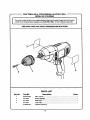
CRAFTSMAN
I
3/8 in. PROFESSIONAL
ELECTRIC
MODEL NO. 315.269460
DRILL
I
The modelnumherwill befound on a plate attachedtothe motorhousing.Always men_ionthe model
number in all correspondence regardingyour ELECTRIC DRILL or when ordedng repair parts.
SEE BACK
PAGE
FOR PARTS
ORDERING
I
J
INSTRUCTIONS
4
2
PARTS lIST
Key No.
1
2
3
4
PaN No.
981570-002
6611903
9411552
9411497
972000-957
Description
Quan.
3/8 in. Chuck ....................................................................................... 1
Screw (Special)...................................................................................
Data Plate ...........................................................................................
1
1
Logo Plate...........................................................................................
Operator's Manual
1
m
13
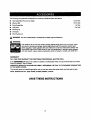
For repair of major brand appliances in your own home...
no matter who made it, no matter who sold it!
il!i=i
iiiiil
1-800-4-MY-HO M EsMAnytime, day or night
iilI
iir-i
(1-800-469-4663)
_ii!!
www.sea
rs.com
To bring in products such as vacuums, lawn equipment and elecb'onics
for repair, call for the location of your nearest Sears Parts & Repair Center
1-800-488-1222
iiii!
Anytime, day or night
www.sears.com
For the replacement parts, accessories and owner's manuals
that you need to do-it-yourself, call Sears PartsDiract sM!
1-800-366-PART
(1-800-366-7278)
7 days a week
www.sears.condpa
ili!!i
6a.=.- 11p.mCST,
rtsdirect
To purchase or inquire about a Sears Service Agreement:
ii!!ii
iiiiii
1-800-827-6655
_55.115!
ii--=_i
!&,'.!
7 a.m. - 5 p.m. CST, Mon.-
Sat.
iilE!!
iilii
iliii
!!t!ii
L5ilII
il!lti
I!H-E,,.
ii!
:==--
*
Para pedir servicio de reparaciOn a domicillo,
y para ordenar piezas con entrega a domicilio:
1-888-SU-HOGAR
=
(1-888-784-6427)
___:_:__;
__;-__
{
HomeCentral"
® Rendered Trademark I
© Seats, Roebuck and Go.
Au Canada pour service an fran_:ais:
® Merce Regi_drsda/
TM
TM
1-877-LE-FOYER =
(1-877-533-6937)
1
Tr ade=n_k of Sear& Roebuck and CO.
M_rca de F_lbrlca de Se_-e, Roebuck a_d Co.