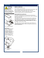
1
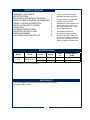
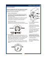
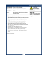
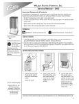
765
OWNERS MANUAL
for
COFFEE GRINDER
MODEL:
8730
Includes:
Installation
Operation
Use & Care
Servicing Instructions
Model 8730
Coffee Grinder
PRINTED IN UNITED STATES OF AMERICA
p/n 70385 Rev. A ECN-12617
M765
040212 cps
WARRANTY STATEMENT
It also does not apply if the serial nameplate has been
removed or unauthorized service personnel perform service.
The prices charged by Bloomfield Industries for its products
are based upon the limitations in this warranty. Seller’s
obligation under this warranty is limited to the repair of defects
without charge by a Bloomfield Industries Authorized Service
Agency or one of its sub-agencies. This service will be
provided on customer’s premises for non-portable models.
Portable models (a device with a cord and plug) must be
taken or shipped to the closest Authorized Service Agency,
transportation charges prepaid, for services.
All electrical equipment manufactured by BLOOMFIELD
INDUSTRIES is warranted against defects in materials and
workmanship for a period of one year from the date of original
installation or eighteen (18) months from the date of shipment
from our factory, whichever comes first, and is for the benefit
of the original purchaser, except that:
a. airpots carry a 30 day parts warranty only.
b. dispensers; i.e., tea and coffee carry a 90 days parts
warranty only, excludes decanters.
THE FOREGOING OBLIGATION IS EXPRESSLY GIVEN IN
LIEU OF ANY OTHER WARRANTIES, EXPRESSED OR
IMPLIED, INCLUDING ANY IMPLIED WARRANTY OF
MERCHANTABILITY OR FITNESS FOR A PARTICULAR
PURPOSE, WHICH ARE HEREBY EXCLUDED.
In addition to restrictions contained in this warranty, specific
limitations are shown below (Additional Warranty Exclusions).
Bloomfield Industries Authorized Service Agencies are located
in principal cities.
BLOOMFIELD INDUSTRIES DIVISION / SPECIALTY
EQUIPMENT MANUFACTURING CORPORATION SHALL
NOT BE LIABLE FOR INDIRECT, INCIDENTAL OR
CONSEQUENTIAL DAMAGES OR LOSSES FROM ANY
CAUSE WHATSOEVER.
This warranty is valid in the United States and void elsewhere.
Please consult your classified telephone directory or your food
service equipment dealer; or, for information and other details
concerning warranty, write to:
Service Parts Department
Bloomfield Industries
P.O. Box 280
Verdi, NV 89439
Phone: (775) 689-5700
Fax: (888) 492-2783
This warranty is void if it is determined that upon inspection by
an Authorized Service Agency that the equipment has been
modified, misused, misapplied, improperly installed, or
damaged in transit or by fire, flood or act of God.
SERVICE POLICY AND PROCEDURE GUIDE
ADDITIONAL WARRANTY EXCLUSIONS
1.
2.
3.
4.
5.
6.
7. Full use, care and maintenance instructions are supplied
with each machine. Those miscellaneous adjustments
noted are customer responsibility. Proper attention will
prolong the life of the machine.
8. Travel mileage is limited to sixty (60) miles from an
authorized Service Agency or one of its sub-agencies.
9. All labor shall be performed during normal working hours.
Overtime premium shall be charged to the customer.
10. All genuine Bloomfield replacement parts are warranted
for ninety (90) days from date of purchase on nonwarranted equipment.
Any use of non-genuine
Bloomfield parts completely voids any warranty.
11. Installation, labor and job check-out are not considered
warranty.
12. Charges incurred by delays, waiting time or operating
restrictions that hinder the service technicians ability
to perform services are not covered by warranty.
This includes institutional and correctional facilities.
Resetting of safety thermostats, circuit breakers,
overload protectors, or fuse replacements unless
warranted conditions are the cause.
All problems due to operation at voltages other than
specified on equipment nameplates; conversion to
correct voltage must be the customer’s responsibility.
All problems due to electrical connections not made in
accordance with electrical code requirements and
wiring diagrams supplied with the equipment.
Replacement of items subject to normal wear, to include
such items as knobs and light bulbs. Normal maintenance
functions including adjustment of thermostats, microswitches,
and replacement of fuses and indicating lights are not
covered under warranty.
All problems due to inadequate water supply, such as
fluctuating, or high or low water pressure.
All problems due to mineral/calcium deposits, or
contamination from chlorides/chlorines. De-liming is
considered a preventative maintenance function and is
not covered by warranty.
SHIPPING DAMAGE CLAIMS PROCEDURE
NOTE: For your protection, please note that equipment in
this shipment was carefully inspected and packaged by
skilled personnel before leaving the factory.
Upon acceptance of this shipment, the transportation
company assumes full responsibility for its safe delivery.
IF SHIPMENT ARRIVES DAMAGED:
1. VISIBLE LOSS OR DAMAGE: Be certain that any
visible loss or damage is noted on the freight bill
or express receipt, and that the note of loss or damage
is signed by the delivery person.
2. FILE CLAIM FOR DAMAGE IMMEDIATELY:
Regardless of the extent of the damage.
3.
CONCEALED LOSS OR DAMAGE: if damage is
unnoticed until the merchandise is unpacked, notify the
transportation company or carrier immediately, and file
“CONCEALED DAMAGE” claim with them. This
must be done within fifteen (15) days from the date the
delivery was made to you. Be sure to retain the
container for inspection.
Bloomfield Industries cannot assume liability for damage or
loss incurred in transit. We will, however, at your request,
supply you with the necessary documents to support your
claim.
xi
TABLE OF CONTENTS
WARRANTY STATEMENT
xi
SPECIFICATIONS
1
FEATURES & OPERATING CONTROLS
2
PRECAUTIONS & GENERAL INFORMATION 3
AGENCY LISTING INFORMATION
3
INSTALLATION INSTRUCTIONS
4
OPERATION
6
CLEANING INSTRUCTIONS
7
SERVICING INSTRUCTIONS
8
WIRING DIAGRAMS
9
EXPLODED VIEW & PARTS LIST
10
Thank You for purchasing this
Bloomfield Industries appliance.
Proper installation, professional
operation and consistent
maintenance of this appliance will
ensure that it gives you the very
best performance and a long,
economical service life.
This manual contains the
information needed to properly
install this appliance, and to use,
care for and maintain or repair the
appliance in a manner which will
ensure its optimum performance.
SPECIFICATIONS
MODEL
STYLE
8730
Single Grinder
VOLTS
WATTS
AMPS
1ø
POWER SUPPLY
CORD
120
375
3.1
NEMA 5-15P
240
375
1.6
VARIOUS*
* contact factory for specific application
APPLICABILITY
This manual applies to the following Bloomfield Industries products:
8730, with or without suffix
1
FEATURES AND OPERATING CONTROLS
Fig. 1 Model 8730 Features & Operating Controls
2
PRECAUTIONS AND GENERAL INFORMATION
WARNING: ELECTRIC SHOCK HAZARD
All servicing requiring access to non-insulated components must be performed by qualified
service personnel. Do not open any access panels which require the use of tools.
Failure to heed this warning can result in electrical shock.
WARNING: INJURY HAZARD
All installation procedures must be performed by qualified personnel with full knowledge of all
applicable electrical codes. Failure could result in property damage and personal injury.
This appliance is intended for commercial use only.
CAUTION:
This appliance is intended for grinding coffee beans. No other
use is recommended or authorized by the manufacturer or its
agents.
EQUIPMENT DAMAGE
This appliance is intended for use in commercial establishments,
where all operators are familiar with the appliance use,
limitations and associated hazards. Operating instructions and
warnings must be read and understood by all operators and
users.
Except as noted, this piece of equipment is made in the USA
and has American sizes on hardware. All metric conversions
are approximate and can vary in size.
The following trouble shooting, component views and parts lists
are included for general reference, and are intended for use by
qualified service personnel.
DO NOT plug in or energize this
appliance until all Installation
Instructions are read and followed.
Damage to the grinder will occur if
these instructions are not followed.
CAUTION:
CUT / PINCH HAZARD
DO NOT reach into the hopper
or discharge chute without first
unplugging the unit from electric
power.
This manual should be considered a permanent part of this
appliance. The manual must remain with the appliance if it is
sold or moved to another location.
AGENCY LISTING INFORMATION
120V model of this grinder is
listed under UL file E98380.
3
INSTALLATION
READ THIS CAREFULLY BEFORE STARTING THE INSTALLATION
CAUTION:
ELECTRICAL
DAMAGE
DO NOT plug in or energize this
appliance until all Installation
Instructions are read and
followed. Damage to the
grinder may occur if these
instructions are not followed.
CAUTION:
UNSTABLE
EQUIPMENT HAZARD
It is very important for safety
and for proper operation that the
grinder is level and stable when
standing in its final operating
position. Provided adjustable,
non-skid feet must be installed
at each corner of the unit.
Failure to do so will result in
movement of the brewer which
can cause personal Injury and/
or damage to grinder.
WARNING:
SHOCK HAZARD
Grinder must be properly
grounded to prevent possible
shock hazard. Electrical shock
will cause death or serious
injury.
Unpack the unit. Inspect all components for completeness and
condition. Ensure that all packing materials have been removed
from the unit.
LEVELING THE UNIT
Verify that an adjustable leg is installed at each corner of the
grinder.
Set grinder in its operating location. Level the grinder. A spirit
level should be placed on the top of the unit, at the edge, as a
guide when making level adjustments.
Level the unit from left to right and front to back by turning the
adjustable feet. Be sure all four feet touch the counter to prevent
tipping.
ELECTRICIAN’S INSTALLATION INSTRUCTIONS
IMPORTANT:
Supply power must match nameplate for voltage and phase.
Connecting to the wrong voltage will damage the brewer or result
in decreased performance. Such damage is not covered by
warranty.
IMPORTANT:
The ground prong of the plug is part of a system designed to
protect you from electrical shock in the event of internal damage.
Never cut off the ground prong nor twist a blade to fit an existing
receptacle. Contact a licensed electrician to install the proper
circuit and receptacle.
REFER TO ELECTRICAL SPECIFICATIONS - Page 1
Check the nameplate to determine correct electrical service
required for the grinder to be installed.
Models 8730 are equipped with a cord and plug.
120V units require a 115 - 125 volt 20 amp circuit (50/60 Hz,
2 wire plus ground, with NEMA 5-15R or 5-20R Receptacle).
220V and 240V units require an appropriate circuit (50/60 Hz,
2-wire plus ground).
4
INSTALLATION (continued)
INITIAL ADJUSTMENTS
The grinder is factory set to deliver the proper amount of ground
coffee for a standard 64 oz. brew. The grinder is set to normal
fine grind specifications. Both throw weight and grind are
adjustable to customer requirements.
A. ADJUST THROW WEIGHT
The amount of coffee per brew determines the strength of
the brewed coffee. The grinder controls the amount of
ground coffee delivered by controlling the grind time. The
timer has two ranges:
.75 seconds to 15 seconds; and, 3 seconds to 60 seconds.
Fill the hopper with coffee beans. Access the timer by
removing the 2” access plug under the grind head.
Select the proper range.
Increase time by turning the control knob clockwise.
Decrease time by turning the control knob counter-clockwise.
Fig. 2 Adjustment Access
SUGGESTIONS:
Bloomfield recommends that
throw weight be measured with
a digital gram scale.
Consult with your coffee roaster
for recommended grind and
throw weight. Then, adjust to
taste for your particular
application.
B. ADJUST GRIND
The coarseness of the grind has a significant effect on the
flavor and richness of the brewed coffee. The grinder can be
adjusted in 12 stages between very fine and regular grinds.
Fill the hopper with coffee beans. Access the grinder
adjustment by removing the front access panel.
Turn the head clockwise for a finer grind, counterclockwise
for a coarser grind. Be sure the head snaps into one of the
detents.
5
For later reference, when the
desired taste is achieved, write
the throw weight, timer setting
and grinder setting on the inside
of the access panel.
Be sure to reinstall access
panels when finished adjusting
the grinder.
OPERATION
CAUTION:
NORMAL OPERATION
CUT / PINCH
HAZARD
Fill the hopper with coffee beans.
DO NOT reach into the
hopper or discharge chute
without first unplugging the
unit from electric power.
Place the appropriate filter paper in your brewer’s brew chamber. Slide
the brew chamber under the grind head on the guide rails.
Press the start button. When the grinder stops, remove the brew
chamber and proceed with your normal brew sequence.
GRINDER PROTECTION DEVICES
The grinder is equipped with a circuit breaker and a shear dish to
protect the motor and grinder burrs in the event of a jam or solid object
entering the grind head.
If the grinder does not operate when the start button is pressed, the
circuit breaker may be tripped. The circuit breaker is located on the
back of the grinder, near the power cord inlet. When tripped, the
center pin of the breaker will “pop” out approximately 1/4”. Press the
pin straight in until it “clicks” to reset.
If the grinder motor runs but the grinder does not grind coffee, the
shear disk may have released. Refer to maintenance procedures for
shear disk replacement.
Fig. 3 Grinder Operation
IMPORTANT:
Before resetting the circuit
breaker or replacing the
shear disk, endeavor to
locate and clear the source
of the jam. Unplug the
grinder from electric power
before reaching into the
hopper or discharge chute.
Fig 4. Reset Circuit
Breaker
6
CLEANING INSTRUCTIONS
PROCEDURE: Clean Coffee Grinder
CAUTION:
PRECAUTIONS: Disconnect grinder from electric power.
SHOCK HAZARD
Do not submerge or immerse
grinder in water.
FREQUENCY:
Weekly
TOOLS:
Mild Detergent, Clean Soft Cloth or Sponge
Soft Bristle Brush
1. Disconnect grinder from electric power.
Empty beans from hopper.
Remove any remaining brew chamber from under grind head.
2. Wipe grounds, solids and any remaining beans from the
hopper.
3. Using a soft bristle brush, brush any remaining coffee
grounds from the discharge chute of the grind head.
4. Wipe inside of hopper and area around the grind head
with a soft clean cloth or sponge moistened with clean water
and mild detergent.
5. Rinse with clean water and allow to air dry.
6. Wipe the exterior of the grinder with a soft clean cloth or
sponge moistened with clean water. Allow to air dry
7. Plug grinder into electric power. Refill hopper with fresh
beans.
Procedure is complete
7
IMPORTANT:
DO NOT use steel wool, sharp
objects, or caustic, abrasive or
chlorinated cleansers to clean
the grinder.
SERVICING INSTRUCTIONS
ADJUST GRINDER BURRS
After replacing grinder burrs, or to compensate for wear from
extended use, it may be necessary to adjust the burrs.
Empty the hopper and run the grinder until there are no more
beans in the burrs. Remove the front access panel.
Note the position of the grind adjustment. Turn the adjustment
head fully clockwise (fine grind) until it is against the stop.
Fig. 5 Adjust Burrs
Using a 9/16” box-end wrench to loosen the jam nut. Use a large
flat-head screw driver to turn the adjustment screw one full turn
counter-clockwise.
Press the start switch. Slowly turn the adjustment screw
clockwise until the burr teeth just begin to click. Then, turn the
adjustment screw counterclockwise 1/8 turn, or until the clicking
stops.
Tighten the jam nut while holding the adjustment screw from
turning. The grinder is now set to the finest grind.
Return the adjustment head to its original position. Refill the
hopper and run several tests to be sure the grind is satisfactory.
Adjust as necessary.
REPLACE SHEAR DISK
Unplug the grinder from electric power. Empty the hopper.
Remove the front access panel.
Using a 1/2” socket, remove two hex bolts holding grinder
adjustment head to grinder body.
Remove shear disk cover and broken pieces of shear disk.
Withdraw the feedworm and burr assembly. Clean the inside of
the grinder head and grinder adjustment head. Be sure that no
debris or foreign objects remain in the surface of the burr plates.
Slide the feedworm back onto the motor shaft. Turn the shear
drive so that it engages the motor shaft.
Align the slot in the feedworm with the slot in the shear drive.
Insert a new shear disk and replace the shear cover.
Reinstall grinder adjustment head. If replacing the wooden plug,
be sure to install it so that the flat end is toward the shear cover.
Be sure it is properly aligned and the bolts are securely tightened.
Fig. 6 Replace Shear Disk
Reconnect to electric power. Refill the hopper and run several
tests to be sure the grind is satisfactory. Adjust as necessary.
8
WIRING DIAGRAM
9
EXPLODED VIEW & PARTS LIST
8730 CABINET AND ASSOCIATED COMPONENTS
10
EXPLODED VIEW & PARTS LIST (continued)
8730 MOTOR & GRINDER COMPONENTS
11
Bloomfield Industries proudly supports CFESA
Commercial Food Equipment Service Association
Bloomfield Industries, Inc.
Division of Carrier Commercial Refrigeration
In US and Canada
Telephone: 775-689-5700
Fax:
888-492-2783
Fax:
800-356-5142 (for orders only)
website: www.wellsbloomfield.com
PRINTED IN UNITED STATES OF AMERICA