1
Operator's Manual
Ip..,,ss.°...I
356 mm (14 in.) ABRASIVE
CUT-OFF MACHINE
Model No.
315.212900
Save this manual for
future reference.
• Safety
• Features
CAUTION: Read and follow
all Safety Rules and Operating
Instructions before first use of
this product.
• Adjustments
• Operation
• Maintenance
• Parts List
Customer Help Line: 1-800-932-3188
Sears, Roebuck and Co., 3333 Beverly Rd., Hoffman
Visit the Craftsman web page: www.sears.com/craftsman
983000-037
4-02
Estates,
IL 60179
USA
i
Table of Contents .................................................................................................................................................
•
Warranty
•
Rules for Safe Operation
•
Electricel .............................................................................................................................................................
•
Unpacking, Loose
•
Features
•
Adjustments .................................................................................................................................................
10-13
•
Operation
.....................................................................................................................................................
13-16
•
Maintenance
................................................................................................................................................
16-17
•
Troubleshooting
•
Exploded
•
Parts Ordering / Service
and Introduction
2
...................................................................................................................................
2
.................................................................................................................................
Parts, and Product Specifications
3-5
6
..........................................................................................
7
...........................................................................................................................................................
...........................................................................................................................................
Views and Repair Parts Lists .......................................................................................................
8-9
17-18
20-25
....................................................................................................................................
26
FULL ONE YEAR WARRANTY
If this product fails due to a defect in material or workmanship within one year from the date of purchase,
Sears will repair it free of chargeContact a Sears SerVice Center for repair.
It this product
of purchase.
is used for commercial or rental purposes, this warranty applies only for g0 days from the date
This warranty gives you specific legal rights, and you may also have other rights which vary from state to state,
Sears, Roebuck
and Co., Dept. 817WA,
Hoffman
Estates,
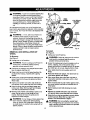
Your saw has many features for making cutting
operations more pZeasantand enjoyable, Safety,
pedormance and dependability have been given top
priorityin 'thedesign of this saw making it easy to
maintain and operate.
_,
IL 60179
CAUTION:
Carefully read through this entire
operator's manua[ before using your new saw.
Pay close attention to the Rules For Safe
Operation, and all Safety Alert Symbols including
Danger, Warning and Caution. if you use your
saw prot0erly and only for what it is intended, you
will enjoy years of safe, reliable service.
Look for this symbol to point out important
means attention!!! Your safety is involved.
j_
safety precautions.
It
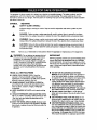
WARNING:
The operation of any power tool can result in foreign objects being thrown into your eyes,
which can result in severe eye damage. Before beginning tool operation, always wear safety
goggles or safety glasses with side shields and a full face shield when needed. We
recommend Wide Vision Safety Mask for use over eyeglasses or standard safety glasses
with side shields_ A[ways wear eye protection which is marked to comply with ANSI Z87,1.
The purpose of safety symbols is to attract your attention to possible dangers. The safety symbols, and the
explanations with them. deserve your careful attention and understanding. The safety warnings do not by
themselves eliminate any danger. The instructions or warnings they give are not substitutes for proper accident
prevention measures.
SYMBOL
A
MEANING
SAFETY ALERT SYMBOL:
Indicates danger, warning or caution. May be used in conjunctionwith other symbols or pictographs.
DANGER: Failure to obey a safety warningwill result in serious injury to yourself or to others.
Always follow the safety precautionsto reducethe risk of fire, electric shock and personal injury.
A
A
Note:
_k
CAUTION: Failure to obey a safety warning may result in propertydamage or personalinjuryto
yourself or to others. Always follow the safety precautionsto reduce the risk of fire, electricshook
and personal injury.
Advises you of information or instructionsvital to the operation or maintenance of the equipment.
IMPORTANT
WARNING:
Do not attempf to operate this tool
until you have read thoroughly and understand
completely all instructions, safety rules, etc.
contained in this manual. Failure to comply can
result in accidents involving tire, electrical shock,
or serious personal injury. Save operator's
manual and review frequently for continuing safe
operation, and instructing others who may use
this tool.
READ
•
WARNING;
Failure to obey a safety warning can resuR in serious injuw to yourself or to others.
Always follow the safety precautions to reduce the risk of fire, electric shock and persona] injury.
Servicingrequires extreme care and knowledgeof the
system and shouldbe performedonly by a qualified
servicetechnician. For service we suggest you return
the tool to your nearest Sears store or repair center for
repair, Always use originalfactory replacement parts
when servicing.
ALL INSTRUCTIONS
•
KNOW YOUR POWER TOOL. Read the
operator's manual carefully. Learn the saw's
applications and limitations as well as the specific
poten'_ialhazards related to this tool.
•
GUARD AGAINST ELECTRICAL SHOCK by
preventing body contact with grounded surfaces
such as pipes, radiators, ranges, refrigerator
enclosures,
•
•
KEEP GUARDS
order.
•
•
REMOVE WRENCHES AND ADJUSTING KEYS.
Get in the habit of checking - before turning on tool
- that hex keys and adjusting wrenches are removed from tool.
•
•
IN PLACE and In good working
•
KEEP THE WORK AREA CLEAN. Cluttered work
areas and work benches Invite accidents. DO NOT
leave tools or pieces of wood on the saw while it is
in operation.
•
DO NOT USE IN DANGEROUS ENVIRONMENTS. Do not use power tools near gasoline or
other flammable IJcluids,in damp or wet locations,
or expose them to rain. Keep the work area well lit.
KEEP CHILDREN AND VISITORS AWAY. All
visitors should wear satety gIasses and be kept a
safe distance from work area. Do not let visitors
contact tool or extension cord while operating.
MAKE WORKSHOP CHILDPROOF
with padlocks
and master switches or by removing starter keys.
DO NOT FORCE THE TOOL it will do the job
better and more safely at the rate for which it was
designed.
USE THE RIGHT TOOL FOR THE JOB. Do not
force the tool or attachment to do a job it was not
designed for, Use it only the way it was intended.
USE THE PROPER EXTENSION CORD. Make
sure your extension cord is in good condition. Use
only a cord heavy enough to carry the current your
product will draw. An undersized cord will cause a
drop in line voltage resulting in loss of power and
overheating. A wire gage size (A.W.G.) of at least
14 is recommended for an extension cord 25 feet
3
or less in length, tf in doubt, use the next heavier
gage. The smatler the gage number, the heavier
the cord,
• INSPECT EXTENSION CORDS PERIODICALLY
and replace if damaged.
• CRESS PROPERLY- DO not wear loose clothing,
neckties, dngs, bracelets, or other jewelry. They
can get caught and draw you into moving parts.
Rubber gloves and nonslip footwear are
recommended when working outdoors. Also wear
protective hair covering to contain long hair.
• ALWAYS WEAR SAFETY GLASSES WITH SIDE
SHIELDS. Everyday eyeglasses have only impactresistant lenses; they are NOT safety glasses.
• PROTECT YOUR LUNGS. Wear a face or dust
mask if the cutting operation is dusty.
• PROTECT YOUR HEARING.
Wear hearing
protection during extended periods of operation,
• SECURE WORK. Use clamps or a vise to hold
work when practical. It's eefer than using your hand
and it frees both hands to operate tool.
• DO NOT ABUSE CORD. Never yank cord to
disconnect it from receptacle, Keep cord _'om heat,
oil, and sharp edges.
• DO NOT OVERREACH.
Keep proper tooting and
balance at all times.
•
•
•
•
•
•
•
MAINTAIN TOOLS WITH CARE. Keep tools sharp
and clean for better and safer performance, Follow
instructions for lubricating and changing
accessoriesDISCONNECT
ALL TOOLS. When net in use,
before servicing, or when changing attachments,
wheels, bits, cutters, etc., all tools should be
disconnected.
AVOID ACCIDENTAL
STARTING. Be sure switch
is off when plugging in.
USE RECOMMENDED
ACCESSORIES.
The use
of improper accessories may cause risk of injury.
Consult operator's manual for recommended
accessories.
NEVER STAND ON TOOL. Serious injury could
occur it the tool is tipped or if the wheel is
unintentionally contacted.
CHECK DAMAGED PARTS. Before further use of
the tool, a guard or other par that is damaged
should be carefully checked to determine that it will
operate properly and perform its Intended function.
Check for alignment of moving parts, binding of
moving parts, breakage of parts, mounting and any
other conditions that may affect its operation. A
guard or other part that is damaged must be
properly repaired or replaced by an authorized
service center to avoid risk of personal injury.
NEVER LEAVE TOOL RUNNING UNATTENDED.
TURN THE POWER OFF. Do not leave tool until it
comes to a complete step,
•
USE ONLY CORRECT WHEELS. Do not use
wheels with incorrect size holes. Never use wheel
washers or wheel screws that are defective or
Incorrect, The maximum wheel capacity of your cutoff machine is 14 in. (356 ram).
'= DO NOT REMOVE THE MACHINE'S WHEEL
GUARDS. Never operate the machine with any
guard or cover removed. Make sure all guards are
operating properly before each us_'.
m KEEP HANDS AWAY FROM CUTTING AREA.
Keep hands away from wheel. Do not reach
underneath work or around or under the wheel
whi(e the wheel is rotating. Do not attempt to
remove cut material whiSe wheel is moving.
•
WHEEL
•
NEVER USE IN AN EXPLOSIVE ATMOSPHERE.
Normal sparking of the motor or sparking from
cutting metal could ignite fumes.
INSPECTTOOL
CORDS PERIODICALLY
and if
damaged, have repaired at your nearest Sears
Authorized Service Center. Stay constantly aware
of cord location and keep it well away from the
rotating wheel.
USE OUTDOOR EXTENSION CORDS. When tool
is used outdoors, use only extension cords with
approved ground connection that are intended for
use outdoors and so marked.
•
•
•
•
COASTS
AFTER TURN OFF.
DO NOT USE TOOL IF SWITCH DOES NOT
TURN IT ON AND OFF. Have defective switches
rep(aced by an authorized serv[ce center.
KEEP TOOL DRY, CLEAN, AND FREE FROM
OIL AND GREASE. Always use a clean cloth
when cleaning. Never use brake fluids, gasoline,
petroleum-based products, or any solvents to clean
tool.
m ALWAYS SUPPORT LONG WORKPIECES.
To
minimize risk of tipping machine, always support
long workpieces.
• BEFORE MAKING A CUT, BE SURE ALL
ADJUSTMENTS
ARE SECURE.
m ALWAYS USE THE VISE CLAMP to secure the
workpiece.
• NEVER TOUCH WHEEL or other moving parts
during use.
• NEVER START THE CUT-OFF MACHINE WHEN
THE WHEEL IS IN CONTACT WITH THE
WORKPIECE.
m NEVER cut more than one workpieca at a time,
DO NOT STACK more than one work.piece on the
machine base at a time.
•
NEVER PERFORM ANY OPERATION "FREEHAND". Always secure the workpiece to be cut in
the vise.
• NEVERhand
•
NEVER reach behind, under, or within three inches
of the wheel and its cutting path with your hands
and fingers for any reason.
ONLY USE A CUT-OFF WHEEL RATED FOR
3300 RPM OR GREATER and manufactured in
compliance with ANSi B 7.1. Always store wheels
in a dry place with tittle temperature variation.
•
•
NEVER reach to pick up a workplace, a piece of
scrap, or anything else that is in or near the cutting
path of the wheel.
BEFORE cUTrlNG,
press the trigger switch and
allow the cut-off wheel to reach full speed before
cutting.
•
•
AVOID AWKWARD OPERATIONS
AND HAND
POSITIONS where a sudden slip could cause your
band to move into the wheel. ALWAYS make sure
you have good balance.
•
MAKE SURE THE WORK ARF.A I:_S AMPLE
LIGHTING to see the work and tf'l_t no obstruc,
tlons will interfere with safe operation BEFORE
performing any work using your cut-off machine.
DO NOT OPERATE THIS TOOL WHILE UNDER
THE INFLUENCE OF DRUGS, ALCOHOL, OR
ANY MEDICATION,
hold a workplace. Workpiece will
become very hot while being cut.
•
•
NEVER stand or have any part of your body in line
with the path of the wheel.
•
ALWAYS release the power switch and aJlow the
wheel to stop relating before raising it out of the
workpiece.
•
DO NOT TURN THE MOTOR SWITCH ON AND
OFF RAPIDLY. This could cause the wheel to
loosen and could create a hazard. Should this ever
occur, stand clear and allow the wheel to come to
a complete stop. Disconnect your cut-off machine
from the power supply and securely retighten the
wheel arbor bolt.
•
REPLACEMENT
PARTS. All repairs, whether
electrical or mechanical, should be made at a
Sears Authorized Service Center.
•
WHEN SERVICING use only identical Sears
replacement parts. Use of any other parts may
create a hazard or cause product damage.
•
NEVER leave the cut-off machine unattended
while connected to a power source.
•
IF ANY PART OF THIS CUT-OFF MACHINE IS
MISSING or should break, bend, or fail in any way,
or should any electrical component fail to perform
properly, shut off the power switch, remove the
machine plug from the power source and have
damaged, missing, or failed parts replaced before
resuming operation.
MAKE SURE THE CUT-OFF WHEEL IS SECURELY MOUNTED as described in the operating
instructions before connecting the tool to a power
supply. Do not tighten wheel excessively, since this
can cause cracks.
•
•
•
•
•
•
_1
SAVE THESE INSTRUCTIONS.
Refer to them
frequently and use them to instruct other users. If
you loan someone this tool, loan them these
instructions also
WARNING:
some dust created by power
sanding, sawing, grinding,drilling,and other
constructionactivities containschemic_.lsknown
to cause cancer, birth defects or other reproductive harm. Some examples of these chemicals
are:
lead from lead-based paints,
crystalline silica from bricks and cement
and other masonry products, and
arsenic and chromium from chemicallytreated lumber.
Your riskfrom these exposures varies, depending
on how often you do this type of work, To reduce
your exposure to these chemicals,work in a well
ventilatedarea and work with apgroved safety
equipment, such as those dust masks that are
speciallydesignedto filter out microscopic
particles.
CHECKTHE
WHEEL FOR FISSURES AND
CRACKS, and test for normal operation prior tO
use.
ALWAYS EASE THE ABRASIVE WHEEL
AGAINST THE WORK PIECE when starting to cut.
A harsh impact can break the wheel.
SAVE THESE
ALWAYS STAY ALERT! DO not allow familiarity
(gained from frequent use of your cut-off machine)
to cause a careless mistake. ALWAYS REMEMBER that a careless fraction of a second is sufficient to inflict severe injury
STAY ALERT AND EXERCISE CONTROL. Watch
what you are doing and use common sense, DO
not operate toot when you are tired. DO not
rush.
INSTRUCTIONS
5
EXTENSION
CORDS
ELECTRICAL
Your Sears Abrasive Wheel Cut-off Machine is
powered by a precision built electric motor. It should
be connected to a power supply that is 120 volts,
60.Hz. If the machine does not operate when plugged
into art outlet, double check the power supply.
Use only 3-wire extension cords that have 3-prong
grounding plugs and 3-pole receptacles that accept
the tool's plug. When using a power tool at a considerable distance from the power source, use an
extension cord heavy enough to carry the current that
the tool will draw. An undersized extension cord wiJl
GROUNDING
cause a drop in line voltage, resulting in a loss of
power and causing the motor to overheat. Use the
chart provided below to determine the minimum wire
size required in an extension cord. Only round jacketed cords listed by UndeP,vriter's Laboratories (UL)
should be used.
Length
of Extension
Up to 25 feet
26-50 feet
Cord
CONNECTION
INSTRUCTIONS
In the event of a malfunction or bre_:ciown, grounding
provides a path of least resistance for electric current
to reduce the risk of electric shock. This tool is
equipped with an electric cord having an equipmentgrounding conductor and a grounding plug. The plug
must be plugged into a matching outlet that is properly installed and grounded in accordance with all
local cedes and ordinances.
Wire Size (A.W.G.)
14
12
Do not modifythe plug provided. If it will not fit the
outlet, have the proper outlet installedby • qual{fied
electdcfan. Improper connectionof the equipmentgroundingconductorcan resultin a risk of electric
shock. The conductorwith insulationhaving an outer
sudaco that is green with or without yellow stripes is
the equipment-groundingconductor. If reps.iror
replacement of the electriccord or plug is necessary,
do not connectthe equipment-groundingconductorto
a live ten'ninal,
When working with the tool outdoors, use an extension cord that is designed for outside use. This is
indicated by the letters WA on the cord's jacket.
Before using an extension cord, inspect it for loose or
exposed w_rss and cut or worn insulation.
CAUTION:
Keep the cord away from the
cu'_ingarea and position the cord so that it will
not be caught on material, tools, or other objects
during cutting.
Check with a qualified electrician or service personnel
it the grounding instructions _,re not completely
understood, or if in doubt as to whether the tool is
properly grounded.
"Repair or repl_ee a damaged or worn cord immediately.
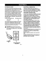
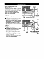
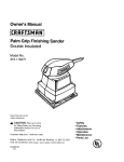
This tool is intended for use on a circuit that has an
outlet like the one shown in Figure 1. It also has a
grounding pin like the one shown.
COVER OF GROUNDED
OUTLET BOX
Fig. 1
6
Your abrasive cut-off machine has been shipped
completely assembled.
•
Remove all loose parts from the carton.
•
Remove the packing materials from around your
machine
If any parts are damaged or missing, do not attempt to
plug in the power cord and turn the switch on untilthe
damaged or missing parts are obtained and are
installedcorrectly.
._
• Carefully Ii_the cut-off machine from the carton
and place it on a level work surface. This is a
heavy Ioo1. To avoid back injury, get help when
needed,
•
•
•
WARNING:
If any parts are missingdo not
operate your cut-off machine untilthe missing
parts are replaced. F_tura to do so could result
in possibleserious injury.
LOOSE
Do not discard the packing materials until you have
carefully inspected the machine, identified all loose
parts, and satisfactorily operated your new abrasive cut-off machine.
PARTS
LIST
The following itemsare includedwith your Abrasive
Cut-off Machine;
[] 14 in. (356 ram) - Abrasive Wheel- installed on
Machine
Your cut-off machine has been shipped with the
machine a.rm looked in the down position. To
release the arm. push clown on top of the machine
arm and pull the arm lock lever. See Figure 3.
• Wheel Wrench - 8 mm Hax Kay - Stored on
Machine
•
Hand pressure should remain on the machine arm
to prevent sudden rise upon release of the arm
lock lever.
Operator'sManual
• Examine allparts to make sure no breakage or
damage has occurred during shipping.
Wheel Type
Reinforced Abrasive Wheels
Wheel Diameter
14 in. (356 ram)
Wheel Thickness
1/8 in. (3,2 ram)
Wheel Arbor Hole
Overall Wheel Size
No Load Speed
Rating
Input
Net Weight
,_
Fence Angle
Right
45 U
- • Left
1.0 in. (25,4 ram)
14in. x1/ain, xtin.
356 mm x 3,2 mm x 25.4 mm
3300 RPM
Vise Clamp Angle
Right or Left
Angle Stock
15 Amp
65 Ibs. (30 kg.)
Flat Metal Stock
WARNING:
This cut-off machine has been
designed for cuffing metals, using reinforced
abrasive cut-off wheels only, Do not remove the
wheel, install a steel blade, and attemptto cut
other types of materials such as wood, masonry.
etc. Attemptingto cut these othertYpes of
materials could cause an accident resulting in
possible serious personalinjury.
_,
7
45 °
Maximum CuttingCapacities:
Round Pipe
120 Volts, AC/DC
0o
5 in. (127 mm) OUtside diameter
6-t/2 in. wide x 3-5/16 in. tall
165 mm wide x 84 mm tall
8-1/16 in. wide x 2-5/16 in. tall
205 mm wide x 59 mm tall
WARNING:
Do not attempt to modify this tool
or create accessories not recommendedfor use
with this tool. Any such alteration or modification
is misuse and could resultin a hazardous
conditionleading to possiblesedous personal
injury.
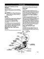
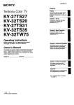
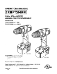
KNOW YOUR ABRASIVECUT-OFF
MACHINE
side of the wheel It retracts over the upper wheel
guard as the wheel is lowered into the workplace.
VISE CLAMP
See Figure 2.
See Figures 2 and 3.
Before attempting to use your machine, familiarize
yourselfwith all operating features and safety requirements.
F, vise clamp has been provided with your cut-off
machine. It is located on the end of the vise screw and
provides greater contTolby clampingthe workpiece to
the fence. It also prevents the workp:_cefrom creep.
ing toward the wheel during a cutting operation.
WARNING:
Do not e,ow familiarity with your
machine to make you careless. Remember that
a careless fraction of a second is sufficientto
inflict severe injury.
ADJUSTABLE
see Figure 2.
MOTOR
WHEEL
A 14 in. (356 ram) abrasive wheel is included with
your cut-off machine. It will cut materials up to S in.
(127 ram) thick or 8 in. (203 ram) wide, depending
upon the thickness or width of the material and the
setting at which the cut is being made.
SELF-RETRACTING
GUARD
See Figure 2.
LOWER
ASSEMBLY
The fence on your cut-off machine has been provided
to supportthe workplace and provide clamping
support to the vise for holdingyour workpiece securely
when making all cuts. It is an adjustable flip fence
assembly that has been providedto make your cut-off
machine more versatile. It adjusts45" to the right for
making angled cuts. It has an extension blockthat flips
down when making cuts in tall or thick stock, such as
square stock or tube stock. The extensionfence flips
up out of the way when making cuts in stock that is
thin or wide, such as angle stock.
See Figure 2.
This machine has a strong motorwith sufficientpower
to handle tough cuffing jobs. It also has externatly
accessible brushes for ease of servicing,
14 in. (356 mm) ABRASIVE
See Figure 2.
FLIP FENCE
QUICK LOCK-RELEASE
see Figure 2.
WHEEL
LEVER
A quick lock-re]easeleverhas been providedon your
cut-offmachine.Thisfeature allowsyou to openand
c]osethe viseclamp quickJywithoutrepetitiveturningof
the vise crank handle.
The lewer wheel guard provides protection from each
MACHINEARM
SWITCHTRIGGER
MOTOR
LOWER
WHEEL GUARD
ADJUSTABLE
FUPFENCE
EXTENSION
FENCE
14 In, (356 ram)
ABRASIVEWHEEL
GUICK LOCKRELEASE LEVER
V_ECLAMP
VISE
CRANKHANDLE
VISESCREW
B
Fig. 2
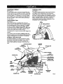
CARRYING
HANDLE
TRIGGER
LOCK
See Figure 4.
To prevent unauthorizeduse of your cut-off machine,
we suggest that you disconnect it from the power
supply and lock the switch in the off position.To lock
the switch,install e padlock (not included)through the
hole in the switch trigger. A lock with a shackle up to
9/32 in, diameter may be used. When the lock is
installedand locked, the switch is ino'l_bra.ble.
Store
the padlock key in another location.
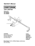
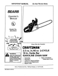
See Figure 3.
For convenience when carrying or trensporting your
cut-off machine from one place to another, a carrying
handle has been provided on top of the machine arm
as shown figure 3. To transport, turn off and unplug
your machine, then lower machine arm and look it in
the down position. Lock machine arm by pushing in
arm lock lever.
LOCK-ON
BU'I-ION
See Figure 3.
Your cut-off machine is equipped with a lock-on
feature, which is convenient when continuous cutting
for extended periods o1'time is required. To engage
the lock-on feature, depress switch trigger, push in
and hold the lock-on button located on the side of the
PADLOCK
handle, then release switch trigger. Release lock-on
button and machine wi{I continue running.
To release lock-on feature, depress switch trigger and
release.
If you have the lock-on feature engaged during use
and your machine becomes disconnected from power
supply, disengage the lock-on feature immediately.
SPINDLE
LOCK
BU'FI'ON
A spindle lock button has been provided for locking
the spindle which keeps the wheel in your machine
from rotating. Depress and hold the spindle lock
button while installing, changing, or removing wheel
only.
CARRYING HANDLE
SPINDLE
LOCK BuI'rON
Fig, 4
LOCK-ON
BUTTON
MACHINEARM
UPPER
WHEELGUARD
SWRCHTRIGGER
LOWER
POWERCOHD
14in.(356mm)
ABRASWEWHEEL
OUICKLOCKRELEASELEVER
ARM
LEVER
WRENCH
Bmm
HEXKEY
FENCE
LOCK HANDLE
RUBBERFEET
ADJUSTABLE
FUP FENCE
ASSEMBLY
_SECRANK
HANDLE
VISE CLAMP
MACHINE BASE
9
Fig, 3
_,
WARNING:
To prevent accidental starting that
could cause possible serious personal injury,
assemble all parts to your cut.off machine before
connecting it to power supply. Machine should
never be connected to power supply when you
are assembling parts, making adjustments,
installing or removing wheels, or when not in
INNER
WASHER
14in.(356mm)
ABRASIVE
WHEELARBOR
WHEEL
use.
As mentioned previously your cut-off machine has
been factory assembled and adjusted. After extended
use and wear, the wheel will need to be replaced with
a flew one,
_i,
OUTER
WASHER
WARNING:
A 14 in. (356 am) wheel is the
maximum wheel capacity of your cut-off
machine. Never use a wheel that is too thick to
allow outer flange to engage with the flats on the
spindle. Larger wheels will come in contact with
the wheel guards, while thicker wheels will
prevent the bolt from securing the wheel on the
spindle, Either of these situations gould result in
a serious accident and can cause serious
personal injury.
REMOVAL
WHEEL
AND INSTALLATION
SPACER
WHEEL BOLT
OUTERFLANGE
TO Install:
OF
See Figure 5.
•
To Remove:
See Figure S.
• Unplug your cut-off machine.
_1=
•
•
WARNING:
Failure to unplug cut-off m_chine
could result in accidental starting causing
possible serious perSonal injury.
Fig. 5
_i,
.i
Push down on machine arm and pull out arm lock
lever to release machine arm.
•
Raise machine arm to its full raised position. Be
cautious when raising, machine arm is spring
loaded,
Unplug your cut-off machine.
WARNING:
Failure to unplugcut-off machine
could result in accidental starting causing
possibleserious personal injury.
Inspect the replacement wheel for defects such as
cracks, chipping,and correct speed rating. If
defects are found or the speed rating is not greater
than 3300 rpm, do riot use. Select another wheel,
Clean debris from the inner washer and inner
flange.
•
Place new wheel over spacer, then place both on
wheel arbor against inner flange.
•
Rotate lower wheel guard upward, exposing 8 mm
socket head bolt that secures abrasive wheel to
wheel arbor.
•
Clean outer flange, then align flats with flats on
wheel arbor and slide it ontoarbor until it is flush
against wheel.
•
Depress the spindle lock button and rotate bait
uhtJl spindle Jacks, preventing shaft from rotating.
•
•
Using the 8 mm hex key provided, loosen and
remove bolt. Note: Bolt has right hand threads.
Turn bolt counterclockwise to loosen.
Place recessed side of outer washer against arbor,
then insert socket head bolt intothreaded end of
wheel arbor.
•
,_
[] Start threads and turn bolt clockwiseto snugly
tighten.
•
Remove outer washer, outer flange, spacer, and
wheel. Do not remove inner flange or inner
washer. Removal of these two parts are not
required for wheel changes.
•
WARNING:
If inner flange or inner washer has
been removed, replace both before placing
wheel on spacer and wheel arbor. Failure to do
so could cause an accident since wheel will not
Depress the spindlelock button and rotate bolt
until spindlelocks, preventingshaft from rotating.
Using the 8 mm hex key provided,securely tighten
socket head bolt. Note: Bolt has right hand
threads. Turn boltclack'wiseto tighten.
WARNING:
Do not overflghten socket head
bolt Overtightening can cause the new wheel to
crack, resulting in premature failure and possible
serious personal injury.
tighten property.
10
ADJUSTABLE
FLIP FENCE ASSEMBLY
See Figure 6.
The adjustableflip fence assembly (see figure 6) is
used along with the movable vise clamp to providea
clamp for ho(ding your workplace securely when
makingcuts. It also makes your cut-off machine more
versatile_
FENCELOCK
• HANDLE
VISE
CLAMP
The fence can be rotated to obtain cuttingangles from
0_ to 45% It also has an extensionblock that flips up
to allow greater cutting widths in thin stock, or down to
al$owgreater cutting depths in tall or thick stock.
CUTTING ANGLE
See Figure 6.
ADJUSTMENT
[] Unplug your cut-off machine.
SCALI
INDICATOR
_1= WARNING;
Failure to unp(ugcut-off machine
could result in accidental startingcausing
possibleserious personal injury.
•
Loosen me fence lock handle securing fence
assembly.
•
Rotate fence assembly until the desired angle of
cut on the scale is aligned with the indicator in
machine base.
•
For precise cuts, check the angle of cutfor the
fence against the abrasive wheel with a protractor.
bevel square, or other similar device.
FENCE
SCALE
ADJUSTABLEFLIP
FENCE ASSEMBLY
ADJUSTABLE FLIP
FENCE ASSEMBLY
[] Using the fence lock handle, securelytighten the
fence in place at desired angle. See Figure6.
ADJUSTING
WIDTH OF CUT
See Figures 7 and 8.
• Unplug your cut-off machine,
_1,
•
•
EXTENSION
FENCE
WARNING:
Failure to unplug cut-off machine
could result in accidental starting causing
possible serious personal injury.
To increase the width of cut of your cut-off
machine, flip the extension fence up and back as
shown in figure 7. This position is good for cuffing
thin and wide pieces of stock, such as fiat or
angled stock.
Fig. 7
ADJUSTABLEFLIP
FENCEASSEMBLY
To increase the height of cut of your cut-off
machine, flip the extension fence clown as shown
(n figure 8. This position (s good for cufng tall and
thick pisces of stock, such as square or tubs stock.
Fig. 8
11
QUICK LOCK-RELEASE
LEVER
See Figures 9 and 10.
The quiok lock-re[ease lever engages the vise olamp
to be used along with the fence assembly to provide a
vise for securing the workplace to be cut. It also
allows you to open and close the vise quickly without
repetitive turning of the vise crank handle.
USING THE QUICK LOCK-RELEASE
LEVER AND VISE CLAMP
To loosen;
See Figure 9.
• Unplug your cut-off rcaohine.
,_
V_ECRANK
HANDLE
_SE
QUICK LOC_RELEASELEVER
CLAMP
WlTHTHREAD5 NOT ENGAGED
WARNING:
Failure to unplugcut-off machine
could result in accidental starting causing
possible serious personal injury,
•
Release tension on the vise clamp by rotatingthe
vise crank handle 1/2 to 1 turn counterclockwise.
•
Lilt up the quick lock-release lever as shown in
figure 9 and pull back on vise crank handle to slide
open the vise.
Fig. 9
To tighten:
See Figure 10.
• Unplug your cut-off machine.
_1_ WARNING:
Failure to unplug cut-off machine
could result in accidentat starting causing
poss(ble serious persona[ injury.
•
Push the vise crank handle forward to slide the
vise clamp against the workpiece.
•
Rotate the quick lock-release lever forward and
push down as shown in figure 10 to engage its
threads with _e vise screw.
•
Rotate the vise crank handle clockwise to tighten
the vise clamp against the work,piece,
_SE CRANK
HANDLE
VISE
CLAMP
USE
SCREW
QUICK LOC_RELEASE LEVER
WITHTHREADSENGAGED
Fig. 10
12
DEPTH
STOP
The depth stop limits the wheel's downward travel,
allows the wheel to go below the machine base
enough to maintain full cutting capacities.
It
The adjustable depth stop is a nylo¢= bolt threaded into
the base of the machine at the rear. To adjust the
depth stop use an 8 mm wrench to raise or lower the
depth step bolt.
The depth step is factory set to provide maximum
cuffing capacity for the 14 in, (356 ram) abrasive
whee( provided with your cut-off machine.
When the diameter of the wheel has been reduced
due to wear, it may be necessary to adjust the depth
stop to provide ma;,_imum cutting capacity. When a
new a_rasive wheel is installed, it is necessary to
check the clearance of the wheel to the machine base
Support,
DEPTHSTOP
LEVER
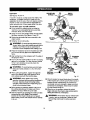
DEPTH STOP ADJUSTMENTS
TO RAISE
See Figure 11.
•
_
Unplug your cut-off machine.
WARNING:
Failure to unplug cut-off machine
could result in accidental starting causing
possible serious personal injury.
•
Push the depth stop lever counterclockwise then
loosen the depth stop bolt that is against the
machine base.
•
The depth stop is lowered by turning the depth stop
bolt clockwise and raised by turning the bolt
counterclockwise.
•
By pressing down on the machine arm, lower the
wheel and check clearance and maximum cutting
distance (distance from adjustable stationary vise
where wheel enters) to front of machine base slot.
•
,_
TO LOWER
DEPTHSTOP
BOLT
Adjust it necessary.
•
Tighten the depth StOpboltwith the B mm hex
key provided then push the depth stop lever
clockwise.
_l,
WARNING:
Cutting steel will cause sparks. DO
not operate in the presence of combustibleor
flammable msterials. Failure to heed this warning
could result in a fire or serious personal injury.
CAUTION:
Do not start your abrasive cut-off
machine without checking for interference
between the wheel and the machine base
support. Damage may result to the wheel if it
strikes the machine base support during
operation of the machine,
APPLICATIONS
(use only for the purposes listed below)
•
•
Cutting all types of metals such as 2 in. x 6 in. steel
framing studs.
• Cutting hard metal iron stock such as square bar
stock and angle iron,
13
Fig. fl
Cutting metal tube and pipe stock.
POWER
MACHINEARM
(HANDLE)
SUPPLY
Before operating your cut-off machine, check your
power supply and make sure it meets the
requirements listed on the tool's data plate. A
substantial voltage drop will cause a loss of power
and machine overheating.
SWITCH
TRIGGER
LOCK-ON
BUTTON
Common causes of power loss and machine
overheating are insufficient extension cord size and
multipletools operating from the same power source.
':MATERIAL
TO BECUT
SWITCH
To turn your cut-off machine
trigger located
in the handle
arm.
ON, depress the switch
portion of the machine
To turn it OFF, release the switch trigger.
LOCK-ON
MACHINE
BASE
BLrrrON
-
To engage the lock-on feature, depress the switch
trigger, push in and hold the lock-on button located on
the side of the handle, then release switch trigger.
Release lock-on button and your machine will
continue running.
Fig. 12
To release the lock-on feature, depress the switch
trigger and release.
If you have the lock-on feature engaged during use
and your machine becomes disconnected from power
supply, or in the event of a power failure, disengage
the lock-on feature immediately.
CU'FFING
See Figures
_k
•
WITH
YOUR CUT-OFF
ADJUSTABLE
FLIP FENCE
ASSEMBLY
MACHINE
VISE
12 and 13.
WARNING:
Do not attempt to cut wood or
masonry with this cut-off machine. Never cut
magnesium or magnesium alloy with this
machine. Failure to comply could result in
serious personal injury.
"C" CLAMP
AREA
MATERIAL
TOBECUT
Fig. 13
To prevent maohlne movement or tipping during
cuttingprocedure, secure cut-of/machine in place
to a workbench or work sudace that is also secure.
WARNING:
Large, circular, or irregularly
shaped material may require additionalmeans of
clampingto be secured in place adequately for
cutting, Use "C" clamps that can be mounted
along the left and front side of the machine base.
Also use blocksto hold material securely. Failure
to comply could result in serious personalinjury.
_1, WARNING:
Always use the vise on the cut-off
machine to prevent accidents that could result in
possible serious personal injury,
_I,
EXTENSION
FENCE
WARNING:
Never stand or have any part ot
yourbody in line with the path of the wheel.
Doing so may cause an accident resultingin
poSsible sedous personal injury;
A
14
WARNING:
To avoid accidental start up of
your out-off machine, always make sure switchis
off and "lock-on"feature is disengaged before
connectingto power source. Failure to heed this
warningcould result in serious personal injury.
MACHINEARM
CUT-OFF
See Figures
14 and 15.
A cut-off is made by cutting across the width of the
workpiece. A straight crosscut is made with the
adjustable flip fence set at the zero degree position.
Ang]ed cut-offs are made with the adjustable flip
fence assembly set at some angle other than zero.
To cut with your cut-off
• Firmly secure the matedal
machine's vise (adjustable
extension fence, and vise
FENCE
LOCK
HANDLE
machine:
to be cut using the
flip fence assembly,
clamp).
•
Using the fence lock handle, loosen the adjustable
flip fence assembly. See Figures 14 and 15.
II
Rotate the adjustable flip fence assembly to the
angle needed,
•
Retighten fence lock handle,
swn'cH
TRIGGER
"
MATERIAL
TO BE CUT
VISE
CRANK
HANDLE
Fig. 14
_1, WARNING:
To avoid serious personal injury,
always tighten fence lock handle securelybefore
making a cut. Failure to do so could result in
movement of the workpiecowhile making a cut.
•
Place the workpiece flat on the machine base with
one surface securely against the adjustable flip
fence.
III Align cutting line on the workpiece with the edge of
the abrasive wheel.
•
Push in the vise crank handle to set the vise clamp
against the workplace. Turn the vise crank handle
1/2 to 1 turn clockwise to securely clamp the
workplace to the fence.
_1,
II
,_,
ADJUSTABLE
FLIPFENCE
VISE
CLAMP
WARNING:
To avoid serious personal injury,
keep your hands at least 3 in. (76.2 mm) from
wheel.
"C" CLAMP
AREA
MATERIAL_"
TO BE CUT
When cutting long pieces, support the opposite
end of the materiel with e roller stand or with a
work surface level with the machine base.
Fig. 15
WARNING:
Never perform any cutting
operation freehand (without placing workpieoe in
• Once it reaches full speed slowly lower the handle
of the machine arm untilthe cut-off wheel comes in
contact with the material being cut. Continue to
use steady and even pressure to obtain a uniform
cut through the workplace. Never force the wheel
into the matedal being cut.
the vise). Material will get hot during cutting
operation, Keep hands off of metal being cut to
avoid serious personal injury.
•
II
EXTENSION
FENCE
Before turning on machine, perform a dry run of
the cutting operation just to make sure that no
problems will occur when the cUt is made.
II When the cut is complete, release the switch
triggerand allow the wheel to stop rotating before
raisingthe wheel out of workpiece.
Start the machine by grasping the handle and fully
squeezing the switch trigger. Allow several
seconds for the wheel to build up to full speed
before letting it come into contact with the material
to be cut,
_1, WARNING:
Do not touch the cut material until
it coolsor you can be burned. Failure to heed
this warningcould resultIn sedous personal
injury.
15
MOUNTING
HOLES
HOLE PATI'ERN FOR MOUNTINGSURFACE
Your cut-off machine should be permanently mounted
to a firm supporting surface such as workbench. The
four bolt holes that secure the feet on the bottom of
the base can be used for this purpose. Using a 6 mm
hex key, remove bolts, washers, and feet from bottom
of cut-off machine. The four mounting holes should be
bolted securely using 8 rnm machine bolts, lock
washers, and flat washers (not included). Bolts should
be of sufficient length to accommodate reck washers,
flat washers, thickness of the workbench, and sufficiently engage bolt hole threads in bottom of the
base.
O
G
0in.
7/16 in, DIA.
HOLE
Lo
17-1/8
Tighten all four bolts securely.
Fig. 16
The hole pattern for mounting to a workbench is
shown in figure 16, Carefully check the workbench
after mounting to make sure that no movement can
occur during use. If any tipping, sliding, or walking is
noted, secure work bench to the floor before operat-
,_
ing,
_,
1
WARNING:
Always make sure your cut-off
machine is securely mounted to a workbench or
an approved workstand. Failure to do so could
result in an accident resulting in possible serious
personal injury.
EXTENSION
WARNING:
When servicing, use only identical
Sears replacement parts. Use of any other part
may create a hazard or cause product damage.
CORDS
The use of any extension cord will cause some loss of
power. To keep the loss to a minimum and to prevent
tool overheating, use an extension cord that is heavy
enough to carry Jhecurrent the tool will draw.
'Awire gage size (A.W.G.) of at least 14 isrecommended
for an extension cord 25 feet or less in length. When
workingoutdoors,use an extension cordthat is suitable
for outdoor use. The cord'sjacket will be marked WA.
GENERAL
Avoid using solvents when cleaning plastic parts.
Most plastics are susceptible to damage from various
types of commercial solvents and may be damaged
by their use. Use a clean cloth to remove dirt, carbon
dust, etc.
A
WARNING: Keep extension cordsaway from
_,
WARNING:
Check extension cords before
each use. If damaged, replace immediately,
CAUTION:
Do not at any time let brake fluids,
gasoline, petroleum-based products, penetrating
oils, etc. come in contact with plastic parts. They
contain chemicals that can damage, weaken or
destroy plastic.
the cutting area and positionthe cord so Mat it
will not get caught on materials, tools, etc.,
during cutting operation.
Never use tool with a damaged cord since
touching the damaged area could cause
electrical shock resulting in serious injury.
LUBRICATION
All of the bearings in this tool are lubricatedwith a
sufficientamount of high grade lubricant for the IHoof
the unit under normal operating conditions.Therefore,
no further lubrication is required.
_IL
16
WARNING:
Always wear safety goggles or
safety glasses with side shields during power
tool operation or when blowing dust. If operation
is dusty, also wear a dust mask,
WARNING:
To ensure safety and reliability, all
repairs --with
the exception of the externally
accessible brushes -- should be performed by a
Sears Authorized Service Center.
BRUSH
BRUSHCAP
BRUSH
ASSEMBLY
REPLACEMENT
.See Figure 17.
Your cut-off machine has externally accessible brush
assemblies that should be periodically checked for
wear,
Proceed as follows
required;
•
when replacement
is
Unplug your cut-off machine.
_1, WARNING:
Failure to unplug cut-oft machine
could result in z,ccidentai starting causing
possible serious personal injury.
•
Remove brush cap with a screwdriver. Brush
assembly is spring loaded and will pop out when
you remove brush cap.
•
Remove brush assembly.
•
Check for wear. Replace both brushes when either
has less than 1/4 in. length of carbon remaining.
Do not replace one side without replacing the
other.
•
Fig. 17
•
Make sure brush cap is oriented correctly (straight)
and replace.
• Tighten brush cap securely. Do not overtighten.
Reassemble using new brush assemblies, Make
sure curvature of brush matches curvature of
motor and that brush moves freely in brush tube.
PROBLEM
Machine does not start
CAUSE
SOLUTION
1, Power cord not plugged in,
2, Power cord is damaged,
1. Plug in cord,
:3. Circuit breaker is tripped.
2. Have the cord replaced at your
nearest authorized service
center.
3. Reset circuitbreaker,
4. Circuit fuse is blown
4. Replace circuitfuse_
5. Switch is damaged or burned out.
5. Have the switch replaced at your
nearest authorized service center
and request a voltage check from
the power company.
17
PROBLEM
CAUSE
SOLUTION
Motor does not reach fall speed or 1. Voltage from power source is low.
power.
2. Circuit is overloaded.
9.
out anything else on circuit.
Motor burned out.
4. Fuses or circuit breakers are
wrong size.
5. Extension cord is too long.
6. Switch is defective.
Motor stalls, blows fuses, or trips
c_rcu_ breakers
1. Request a voltage check from the
power company.
2. Test on e different circuit or with3. Have tool servir,.pd and request
a voltage check from the power
company.
4
Have an electrician replace with
a '(5 amp fuse or circuit breaker
5. Use a shorter extensmn cord.
6. Have the switch replaced at your
nearest authorized service center.
1. Switch is defective
1. Have the switch replaced at your
nearest authorized service center.
2. Voltage from source is low.
2. Request a voltage check from the
power company.
3. Fuses or circuit breakers are
wrOng size or defective.
3. Have an electdcJan replace with
a 15 amp fuse or circuit breaker
Motor overheats.
1. Request a voltage check from the
power company.
2. Wheel is being fed into worktoo fast. 2. Feed wheel into work slower
Machine is noisy when running.
1
Wheel hits table
1. Wheel not properly metalled.
1. See "Removal And InstallationOf
Wheel" section.
2. Depth stop setting incorrect.
2 Adjustthe depth stop. See "Depth
Stop"section.
f.
1 Adjust the depth stop. See "Depth
Stop" section.
Wheel does not cut through
workpteee
1. Motor is overloaded.
Motor needs attention.
Depth stop setting incorrect.
1. Have the motor checked at your
nearest author=zealservice center
2. Wheel worn Ioo much.
2. Replace with a new 14-in. abrasive
cut off wheel.
3. Incorrect cutting operation.
3
Machine vibrates or shakes
1. Wheel Is out-of-round.
1. Replace wheel
excessively.
2. Wheel is chipped
3. Wheel is loose.
4. Machine is not secure.
2. Replace wheel.
5. Work surface is uneven.
surface.
18
See "cut-off" section.
3. Tighten wheel bolt on erbor
4 Check and tighten all hardware.
5. Re!ocate and secure on a flat
__
i
nl
i
iw
19
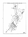
CRAFTSMAN 14 in. (356 mm) ABRASIVE CUT-OFF MACHINE14
15
MODEL NO, 212900
16
19
27
26
2524
23
21
12
30
O
10
29
11
11
8
4
2
3
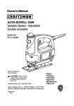
FIGURE A
CRAFTSMAN
14 in, (356 mm) ABRASIVE
CUT-OFF
MACHINE
- MODEL
NO. 212900
I
The modelnumberwillbe roundon a plate attached to the motor housing.Alwaysmention the modelnumber in all correspondenceregardingyour I
Cut-Off Machine or when ordedng repair parts,
I
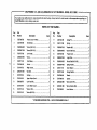
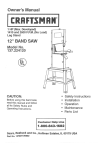
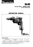
PARTS LIST FOR FIGURE A
Key
No,
=_,
Part
Number
Description
Quan.
Key
No,
Pe_
Number
Desoription
Quen,
1
C357085-BB
Power Cord (14 AWG)...................................1
17
C-357020-BB
SpdngPin......................................................1
2
C357084-BB
Bend Reliel....................................................1
1B
C357017-BB
Spring............................................................I
3
C2600066-BB
* Screw (M5 X 24) ............................................B
19
C2600007-BB
" Washer(MI) ..................................................I
4
C2600067-BB
* Screw (M5 X 22) ............................................ 1
20
C2600008-BB
" Screw (M6X 30) ............................................I
5
C357075-BB
Left Handle....................................................1
21
C357021-BB
PlasticCover................................................ I
6
C2600068-BB
* Screw ............................................................4
22
C2600072-BB
Logo Plate .................................................... I
7
C357071-BB
Cord Clamp ...................................................1
23
C2600005-BB
Wheel Bolt(M10 X 20) .................................. 1
8
C357083-BB
Switch.....................................................:...... 1
g4
C2600004-BB
SpringWasher...............................................1
9
C357078-BB
Right Handle..................................................1
25
C357011-BB
Outer W_.sher................._..............................1
10
C2600070-BB
" Nut (M5) ........................................................g
26
C357010-BB
Flange Washer..............................................2
11
C357007-BB
Bumper ..........................................................2
27
C357009-BB
Wheel ............................................................1
12
C357001-BB
UpperBlade Guard ....................................... 1
28
C357006.BB
Spacer...........................................................1
13
C260006-BB
Lock Nut (M6) ................................................2
29
C2600002-BB
* Screw(M6 X 78) ............................................4
14-
C357014-BB
LowerBladeGuard .......................................1
30
C2600001-BB
• SpringWasher(M6) ......................................4
15
C357015-BB
• Washer(M3) ..................................................1
31
C357005-BB
16
C357016-BB
" Screw(M6 X16) .............................................1
Inner Washer ................................................ 1
* STANDARD HARDWARE ITEM -- MAY BE PURCHASED LOCALLY
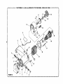
CRAFTSMAN
14 in, (356 mm) ABRASIVE
CUT-OFF
MACHINE
- MODEL NO. 212900
19
16
15
2O
25
Io
1_3
31
4
FIGURE B
5
7
CRAFTSMAN 14 in. (356 ram) ABRASIVE CUT-OFF MACHINE - MODEL NO. 212900
J
Cut-Off
Machine or whenfoundon
orderingrepair
parts,
The modelnumberwillbe
a plateattached
tothe motor housing,Always mention the modalnumberin all correspondenceregardingyour I
m
PARTS LIST FOR FIGURE B
Key
No.
Part
Number
Key
No,
Part
Number
End Cap ........................................................1
t7
C357046-BB
Gear ..............................................................1
Oescrlptlon
Quart.
Descrlpfton
Quan.
1
C357626-BB
2
C2600011-BB
• Flat Washer(M5) ...........................................2
16
C357048-BB
Gear Shaft..................................................... 1
3
C2600010-BB
" SpringWasher(M5) ......................................2
19
C2600023-BB
Flat Pin (M5 X 10) .........................................1
4
C2600009-BB
" Screw (M5 X 12) ............................................ 2
20
C2600024-BB
BallBearing(6203) ........................................ 1
5
C26Q0012oBB " Screw (MS X 12) ............................................ 2
21
C357054-BB
Gear Cover....................................................1
6
C357025-BB
BrushHolder .................................................2
22
C357050-BB
Spdng............................................................1
7
C357024-BB
BrushAssembly.............................................2
23
C2600025-BB
Roll Pin ..........................................................1
8
C357023-BB
BrushCap ..................................................... 2
24
C357051-BB
Stop Pin.........................................................1
9
C357022-BB
Motor Housing...............................................1
25
C2600@20-BB
Ball Bearing(6002) ........................................1
10
C357030-BB
Lead Wire ......................................................1
26
C357041-BB
ArmatureAssembly.......................................1
11
C2600014-BB
Data Plate......................................................1
27
C2600018-BB
* Screw(MS X75) ............................................2
12
C26000! 3-BB
Grommet .......................................................1
26
C2600019-BB
BallBearing...................................................1
i3
C357036-BB
Fie]d Assembly .............................................. 1
29
C357037-BB
Fan Baffle......................................................1
!4
C357044--BB
Gear Case ..................................................... 1
30
C2600017-BB
* Screw (M5 X 12)............................................1
15
C2600021-BB
31
C2600016-BB
" StarWasher (M5) ..........................................1
Ball Bearing (6000) ........................................ 1
16
C2600022-BB
Retaining Ring ............................................... 1
* STANDARD HARDWARE ITEM -- MAY BE PURCHASED LOCALLY
#
CRAFTSMAN 14 in. (356 ram) ABRASIVE CUT-OFF MACH|NE - MODEL NO. 212900
19
16
\
24
13
6
i
9
25
4
3
\
26
7
15
12
i
l"
/
27
.i i
39
jJ
j-
30
Po
j_
.J
54
2
31
52
53
51
45
44
48
46
i7
47
FIGURE C
47
47
CRAFTSMAN
14 in. (356 ram) ABRASIVE
CUT-OFF
MACHINE
- MODEL
NO. 212900
I
I Cut-Off
he model
nu tuberorwillbe
a plate attached to the motorhousing.Always mention the mode[ numberin all correspondenceregardingyour 1
Machine
whenfoundon
orderingrepairparts.
PARTS LIST FOR FIGURE C
L,'I
Key
Part
No.
Number
0escrlp'don
Quan.
Key
No.
Part
Number
Description
Quae,
1
C2600.0,46-BB
Lever ............................................................. 1
28
C357060-t]B
Handle ...........................................................1
2
C2600029-BB
C357056-BB
02600027-BB
29
30
C357081-BB
C2600061-BB
Handle Cover................................................ 1
3
4
Flat Washer(M6) ........................................... t
LeftCover......................................................1
5
6
C2600028-BB
C2600026-BB
" SpringWasher(M6) ...................................... 2
Flat Washer...................................................2
31
32
C2000056-BB
C2600054-BB
7
8
C357060-BB
C2600031-BB
' SocketHex Head Screw(MS X 40) ...............2
PivotShaft ..................................................... t
33
34
C357094-BB
C2600059-BB
35
C357087-BB
" RetainingRing (M161....................................2
* Washer ..........................................................1
9
10
C357114_BB
0357110-BB
Spdng............................................................1
LockWrench .................................................1
Flat Washer................................................... 1
36
37
C2600064-BB
C2600060-BB
" Spdng Washer (M18) ....................................2
11
C260007!-BB
12
13
C260005g-BB
C2600032-BB
PositionStop .........................................,'....... 1
Screw (M6 x 30) ............................................ 1
36
39
C357095-BB
C357093-BB
" SocketHex Head Screw (MIO X 70) ............. 1
14
C2600033-BB
40
41
C357089-BB
C2600058-BB
t5
16
C2600038-BB
C2600034,-BB
t7
18
02606035-BB
G2600047-BB
19
C2_0036-BB
20
21
C2600048-SB
C2600049-BB
' SpringWasher............................................... 1
Wa,sher..........................................................1
22
C2600037-BB
23
C2600039-BB
24
25
02600040-BB
C2600065-BB
26
C2600063-BB
27
C2600062-BB
Right.Cover ................................................... 1
Fence ............................................................1
Ring .............................................................. 1
Yoke..............................................................1
* Roll Pin (M6 X 30) .........................................1
Quick Lock-Re]easeLever ............................ 1
Washer......................................................... 2
Vise Clamp................................................. 1
WarningLabel ...............................................1
Pin .................................................................1
42
43
* Flat Washer(M1) ...........................................1
02600057-BB
" Hex LockNut (M12) ...................................... 1
C2600055-E3B
Bese ............................................................. 1
44
45
C2600042-BB
C2600043-BB
RubberFoot ................................................. 4
" Washer......................................................... 4
46
47
C260004€-BS
C260004,5-BB
• Washer..........................................................4
46
02600051-BB
* Washer (MIO) ................................................ 1
Rol]er Pin (M6 x 20) ....................................... 1
ExtensionFence ...........................................
49
02600052-BB
50
51
C2600053-BB
C2600041-BB
Pin .................................................................1
52
C357 t 20-BB
Hex Key Holder.............................................i
Threaded Rod(M16 X 344) .......................... 1
* Roll Pin (M3 X !4) .........................................1
53
54
C35709_-BB
C2660030-BB
Hex Key.........................................................1
Spring............................................................1
Scale ............................................................. 1
Scale Rivet....................................................2
LookHandle ..................................................1
HexSocket Screw(MIO X 20) ...................... 1
Screw(MS x 42) ............................................4
Hex Soc1<et
Screw (MSx 25) .........................2
SpdngWasher...............................................2
* Washer ..........................................................2
Metal Foot Cover...........................................1
* STANDARD HARDWARE ITEM --MAY BE PURCHASED LOCALLY
For repair of major brand appliances in your own home...
no matter who made it, no matter who sold it!
1-800-4-MY-HOM EsM^nytime,
dayor night
(1-800469-4663)
www.sears.com
To bring in products such as vacuums, lawn equipment and electronics
for repair, call for the location of your nearest Sears Parts & Repair Center.
1-800-488-1222
Anytime,
dayor night
,.I
www.sears,¢om
For the replacement parts, accessories and owner's manuals
that you need to do-it-yourself, call Sears PartsDirect s" t
1-800-366-PART
(t-800-366-7278)-
6_.m- 11pmCST,
,
41!
7 days a week
-p,
:p
www.sears.¢om/partsdirect
To purchase or inquire about a Sears Service Agreement:
1-800-827-6655
'_'_
,F_
it;_i
!_
7 a.m. - 5 p.m. CST, Mon. - Sat.
Para pedir servicio de reparacibn a domi¢ilio,
y para ordenar piezas con entrega a domicilie:
Au Canada pour service en franr...,als: !_
HomeCentral =
O 6cats, Roebuck and Co.
1-877-LE-FOYF-R
__'"
Regist_rod Tcademari( I _" Trmdemar_of S_ar_, Reobuck an_ Co.
_ Mares Raolsb'adll / _ Murca de Flil_rlca _e _art, Roebuck end Co,
s_
=rl_