1
OWNER tS MANUAL
CRRFTSMRN
6,5
orsepower
2600 PSI
.7
High Pressure Washer
Model No:
919.769020
,, Safety
• Assembly
WARNING:
Before
using this
_PRESSURE
product_
read this manual
and follow
all Safety
Rules
and Operating
Instructions,
WASHER
CUSTOMER
HELPLINE
_.. J"
• Operation
= Maintenance
= Parts List
1-800-245-5873
, Espa_ol
Sears,
MGF-76DO=D
12IIIPD
Roebuck
and
Co.,
Hoffman
Estates,
IL 60179
U,S.A,
TABLE OF CONTENTS
Warranty
Safety
....................................................
Guidelines
...................................
2
5-7
Parts ........................................................
17-28
EPA Codes .......................................
29-30
Espa_iol .............................................
31-5t
How to Order Parts ................. Back
Cover
Operation
................................ ...................... 7-11
Service
and Adjustments
....................
FULL ONE YEAR WARRANTY
12-14
15
ON CRAFTSMAN
HIGH
PRESSURE
.......................................... 16
WASHER
For one year from the date of purchase, when this Craftsman High Pressure Washer is maintained
and operated according to the instructions in the owner's manual, Sears will repair, free of charge,
any defect in material and workmanship..
tf your Craftsman Pressure Washer is used for oommeriua! or rental purposes, this warranty
applies only for 90 days from the data of purchase, If this washer is used for rented purposes this
warraty applies for only 30 days from the date of purchase.
FULL
TWO YEAR WARRANTY
ON CRAFTSMAN
ENGINE
For two years from the date of purchase, when this Craftsman engine is maintained and operated
according to the instructions in the owner's manual, Sears will repair, free of charge, any defect in
material and workmanship,
If your Craftsman engine is used for oommeriual or rental purposes, this warranty applies only for
one year from the date of purchase This warranty does not cover expendable items such as spark
plugs and air filters, which become worn during normal use.
Repairs necessary because of operator abuse or negligence, including damage resulting from no
water being supplied to pump or failure to maintain the equipment according to the instructions
contained in the owner's manual, are not covered under warranty,
WARRANTY SERVICE IS AVAILABLE BY RETURNING THE HIGH PRESSURE WASHER TO 'THE
NEAREST SEARS SERVICE CENTER THROUGHOUT THE UNITED STATES. This warranty gives you
specific tegal rights and you may also have other rights, which vary from state to state,
Sears,
Roebuck
15
Troubleshooting
..............................................
...........................................
.....................................................
3-5
Assembly
Maintenance
Storage
and Co., D/817 WA, Hoffman
2
Estates,
IL 60179
SAFETY
lj
i
,
1
IIIIIIIII
,I,IIL
+ ..............
GUIDELINES
+:
.....
- DEFINITIONS
.
+::.-
, .....
II'I'I.........
.
,
_L,Lq,3,
,_jjy_,,_,,
,,
......
..
LI
I
This manual contains informationthat [s Important for you to know and understand. This information relates to protecting
YOUR SAFETY and PREVENTING EQUIPMENT PROBLEMS. To help you recognize this Information, we use the symbob
below. Pleaseread the manual and pay attention to these sections. SAVETHESE DEFINITIONS/INSTRUCTION&
,& WARNING indicates a potentially hazardous
situation which, if not avoided, couldd result in
death or,s,er[ous in,]u__r_,
_. DANGleR indicates an imminently hazardous
sftuation which, if not avoided, will result in
death or serious iniu_.
IMPORTANT
A CAUTION indicates a potentially hazardous situation
which, if not avoided, ma._ result in minor or moderate
i_'u___..
SAFETY INSTRUCTIONS
Improper opetation or maintenance of this product could result In serious injury and property
and understand all warnings and operating instructions before using,
...........
+ -
i i iiiiiii
iiiiii
i
Ull
I III
J+
.......
.
....
mm,ml
.....
........... mmml '
,.
damage, Read
lu
.....
............
................
HOW TO PREVENT IT
HAZARD
WHAT CAN HAPPEN
- Shut off engine and allow it to cool
before adding fuel to the tank,
RISK OF EXPLOSION
OR FIRE
Spilled gasoline and its vapors can
become ignited from cigarette
sparks, electrical arcing, e×haust
gases, and hot engine components
such as the muffler.
Heat will expand fuel in the tank
which could result in spflfage and
possible fire explosion+
° Use care in filling tank to avoid
spilling fuel. Move pressure washer
away from fueling area before
starting engine.,
° Keep maximum fuel level _A" below
top of tank to allow for expansion..
o Operating the pressure washer in an
explosive environment could result
in a fire.
Materials placed against or near the
pressure washer can interfere with
its proper ventilation features
causing overheating and possible
ignition of the materials+
• Improperly stored fuel couid lead to
accidental Ignition. Fuel improperly
secured could get into the hands of
children or other Unqualified persons+
• Store fuel in container approved for
gasoline, in a secure location away
from work area.
• Breathing exhaust fumes will cause
serious injury or death..
o Operate pressure washer in a well
ventilated area. Avoid enclosed areas
such as garages, basements ,etco
• Never operate un[t in a location
occupied by humans or' animals.
, Some cleaning fluids contain substances which could cause injury to
skin, eyes, or lungs+
Use only cleaning fluids specifically
recommended for high pressure
washers. Follow manufacturers
recommendation&
RISK TO BREATHING
++., +.;,+
++,++_+.
•
,+_¢,,'+
+ + ..++
° Operate and fuel equipment tn well
ventilated areas free from obstructions. Equip areas with fire
extinguishers suitable for gasoline
fires,
° Never operate pressure washer in an
area containing dry brush or weeds.
iMPORTANT
HAZARD
RISK OF UNSAFE
OPERATION
SAFETY iNSTRUCTiONS
WttAT CAN HAPPEN
. Unsafe operation of yourpressure
washer could iead to serious injury
or death to you or others.
- Tl_e spray gun/wand is a powerful
cleaning tool that could look like a
toy to a child.
Reactive force of spray will cause
gun/wand to move, and could cause
the operator to slip or fall, or
misdirect the spray., improper control
of gu_wand can result in Injuries to
self and others.
R(SK OF INJURY FROM
SPRAY
SHocK
RISK
OF
RISK
OF FLUID
, Become familiar with the operation
and controls of the pressure washer.
Keep chitdren away from the
pressure washer at all times.
. Never defeat the safety features of this
product.
. Do not operate machine with missing,
broken, or unauthorized parts..
J
Q
Never leave wand unattended while
unit is running.,
Keep work area free of obstacles,
Stand on a stable surface and grip gun/
wand firm_yo Expect the gun to kick
when triggered.
High velocity fluid spray (;an cause
objects to break, propetling particles
at high speed.
• Always wear ANSI approved Z87 safety
glasses_ Wear protective clothing to
protec! against accidental spraying.
Light or unsecured objects can become
hazardous projectiles.
• Never point wand at, or spray people or
anima{s_
. Always secure trigger lock when wand
}s not in service to prevent accidental
operation,
. Never permanently secure trigger in pull
back (open) position,
- Spray directed at electrical outlets or
switches, or objects connected to an
electrical circuit, could result in a fatal
electrical shock,
ELECTRICAL
(cont'd)
HOW TO PREVENT IT
Unplug any electrically operated
product before attempting to clean it,.
Direct spray away from electrlc outlets
and switches.
_--_
INJECTION
RISK OF CHEMICAL BURN
Your washer operatas at fluid
pressures and velocities high enough
to penetrate human and animal flesh,
which could result in amputation or
other serious injury, Leaks caused by
loose fittings or worn or damaged
hoses can result in injection injuries,
DO NOT TREAT FLUID INJECTION AS
A SIMPLE CUT! See a physician
immediately!
- Never place hands in front of nozzle,
,' Direct spray away from self and others..
, Make sure hose and fittings are
tightened and in 9cod condition Never
hold onto the hose or fittings during
operation.
• Do not allow hose to contact muffler.
. Never attach or remove wand or hose
fittings while system is pressurized,
Relieve system pressure before
attempting maintenance or disassembly of equipment
Use only hose and high pressure
accessories rated for 2600 PSI service.
To relieve system pressure, shut off
engine, turn off water supply, and pull
gun trigger until water stops flowing°
, Use of acids, toxic or corrosive
chemicals, poisons, insecticides,
or
any kind of flammable solvent with this
product could result in serious injury
or death,
II
Do not use acids, gasoline, kerosene, or
any other flammable materials in this
product, Use only household
detergents, cleaners and degreasers
recommended for use in pressure
washers.
• Wear protective clothing to protect
eyes and skin from contact with
.sprayed materials.
iMPORTANT
SAFETY
iNSTRUCTiONS
(toni'd)
HAZARD
WHAT CAN HAPPEN
HOW TO PREVENT IT
RiSK OF HOT SURFACES
• Contactwith hotsurfaces, such as
engines exhaust components, could
resutt in serious burn.
• During operation, touch only the control
surfaces of the pressure washer, Keep
children away from the pressure washer
at all times. They may not be able to
recognize the hazards of this product.
Internatlon ai
Symbols
8aferc Aled
" Read
Owners
M_nUal
[ [[_
On Ol1(_
Stop
]_
Fuel
Fue!
8buloff
I'll
Choke
The powerful spray from your pressure washeris capable of causing damage to fragile sui'faces such as: wood, glass,
a_omobite paint, auto stripping and trim. and delicate objects such as flowers and shrubs. Before spraying, check the
item to be cleaned to assure yourself that it is robust enough to resist damage from the force of the spray. Avoid the
use of the concentrated spray stream except for very strong surfaces like concrete and steel.
Operating unit with water supply shut off without flow of water will result in equipment damage. You should
never run this pressure washer for more than 2 minutes without pulling the trigger to allow cool water to enter
the pump and the heated {recircula_ed) water to exit. Running the pressure washer with water supply shut off
will void your warranty,
Carton
0
Contents
. Main Unit pressure washer with wheels
- Handle
° High Pressure Hose
° Chemical Pickup Hose and Filter
Handle
o
High Pressure
Hose
Main Unt= pressure washer
w_th wheels
= Quick Connects (5 included)
GtJn
" Wand
Chemlc_/Pickup
Hose and _tfter
Quick Connects
Nozzles
Gun and Wand
- Bag Containing
- Video Cassette
Video Cassette
Owners' Manual
NezzJe Cieantng Kit
- Owners' Manual
@
- Nozzle Cleaning K(t and Replacement O-Rings
•
°
Engine Oi_
Rubber Isolator and Mounting Hardware
-
Handle Mounting Hardware
©
&
Rubber Isolator and
Mounting Hardware
Handle Mounting
Hardware
o®
RepfacementO-Rings
Tools Required
for Assembly
Remove wood plank from the frame of the unit,,
An adjustable wrench ts required, Discard bolt
and board.
2_
Adjustable wrench
t/2" Socket
_ernove
Pressure
Washer
from
Carton
, Open carton from the top.. Locate and remove from
oat'ton, the parts box, which includes gun, handle,
wand,oil, knobs and bo]ts. Next remove the parts
bag and the handle,,
• Cut carton along dotted lines..
Remove all carton inserts.
- Roll unit through opening in carton.
3.
Note; The pressure and chemical hose are located at
the bottom of the box.
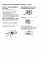
Preparing
the
Pressure
Washer
Mount the rubber isolator to the frame,,
*
To mount isolator place threaded end of bolt
through the washer,.
° Next with washer on bolt place threaded end
of bolt through larger hole in bottom of the
rubber isolator,, Place _.hreaded portion of
isolator through the frqnt hole location where
the wood plank was mounted on the pressure
washer.
, Next plaoe lockwasher over threaded portion
of bolt that has been placed through the
mounting hole in the pressure washer and use
nut to tighten isolator to the frame°
o Tighten nut with an adjustable wrench..
for First Use
Note: Included wffh your pressure washer is a video
tape on how to prepare your unit for operation, it is
recommended you view this tape before performing
the next steps.
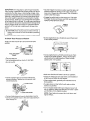
1. insert handle onto frame,
° Insert knobs into the threaded slot in front of the
frame handle and tighten by turning in a clockwise
direction.
o Slide bolts into the slot in the side of the frame
handle and tighten the nut by turning in a clockwise
direction.
n
pa_sul_l
t_L11"
L0._/
.
c_-BoL'r
4.
Connect wand with nozzle assembly to gun.. To
tighten, turn knob in clockwise direction. Hand
tlghten_
Out tie wrap off of h{gh pressure hose° Unwind
high pressure hose to attach the threaded end to
the gun° Tighten with adjustable wrench.
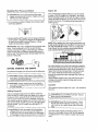
6.
,
Your units pump is shipped with a
temporary plug that must be replaced with a
breather cap, This plug is located over the
pump's oil port. Unscrew and remove this plug.
Remove the breather cap from the bag attached
to the plug and install it in the pump's oil port,,
Connect chemical hose to the chemical injector
hose barb on pump,
_REATHER
CAP
CHEMICAL
INJECTOR
Hose
PUMP
_
AUTION: Failure t_-replace the plug will result
in serious pump damage.
g.
7,
Place assembled gun and wand on pressure
handle bracket as shown,
Connect high pressure hose to the quick connect
outlet on pressure washer,
QUICK
CONNECT
Checklist
Before going any further please review the foHowlng:
NOTE; Always keep hose away from engine
muffler,
- Be sure you have completed assembly instruction,,
. Double check all fittings to be sure they are tight.,
IMPORTANT= Before any attempt to start your pressure washer be sure to check engine oil (See Operation
under Engine Oil, page 9,,)
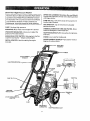
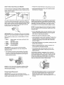
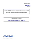
Know Your High Pressure
Washer
Read this 0 wner's Man ual and Safety Rules before
operation of yourHigh Pressure Washer Compare
this ilFustratlon with our pressure washer to familiarize
yourself with the location of various controls and
adjustments, Save this manual for future reference,
PUMP- Develops high pressure,
ENGINE OIL FILL- Place where engine oil is poured,
PRESSURE REGULATOR- Allows you to adjust the
pressure of the outlet stream.
ENGINE RUN/STOP SWITCH- Sets engine in starting
mode for recoil starter - Stops running engine,,
RECOIL STARTER-, Used for starting the engine
manually,
SPRAY GUN ASSEMBLY (Contains Gun and Wand) .Cbhtrols the application of water onto cleaning surface
with trigger device,
PUMP OIL FILL- Port where pump oil is poured and
breather cap is located.
GAS TANKJCAP* Cap is removed and unleaded
gasoline Jspoured.
CHEMICAL INJECTION TUBE AND FILTER- Mixes
water and detergent in outlet water flowo
HIGH PRESSURE OUTLET- Connection for high preso,
sure hose_
CHOKE- Lever used for startlng unit,
QUICK CONNECT NOZZLES- Tips used for various
degrees of spray patterns,
SPRAY GUN
ASSEMBLY
HANDLE
QUICK CONNECT
NOZZLES
HIGH PRESSUt
i
CHOKE
LEVER
GAS TANK
CAP
MUFFLER
THROTTLE
PUMP OIL
I
PRESSURE
ADJUSTABLE
CHEMICAL
INJECTOR
PUMP
WATER INLET
CONNECTION
HIGH PRESSURE OUTLET
Stopping
Your Pressure
Washer
A CAUTION: Do notrun pump without the water
supply connected and turned on., Failure to do so
will result in pump damage,
• To turn pressure washer off place the on/stop switch
to the stop position.
Simply shutting OFF engine will not release pressure
in the system, Squeeze the trigger on the spray gun
for about 3 seconds to reiieve pressure. Spray
stream witl decrease in length,
IMPORTANT: This unit is equipped with a thermal relief
valve. If unit is allowed to run for several minutes
without pressing the trigger on the spray gun, several
drops of water may be released through thls valve to
cool the unit. The heated water will be purged from the
bottom of the pump.
BEFORE
STARTING
ITHE
ENGINE
To operate the engine you will need to do the folJowing,
,A, CAUTION; Always check engine olllevel before
every start,. Running engine low of oil or out of oil
could result in serious damage.
,& CAUTION; Always check pump oil level before
every start,. Running pump low on oit could result
in pump damage,,
Adding
Pump
Engine
Oil
Your unit has been shipped without oil in the engine,
A bottie of SAE 30 weight oil is included in the carton..
Remove oil plug located on the side of engine. Using a
funnel, fill engine crankcase up to the last thread in the
oil port. Pour slowlyo Oil reading Will be inaccurate on
unlevel ground..
NOTE." When adding oil to the engine crankcase, use
a high quality detergent oil classified "For Service SF,
SG, SH rated SAE 30 weight". Use no special additives, Select the oil's viscosity grade according to
your expected operating temperatures.
•................ SA_._,_,_._'er_d_
Air cooled engines run hotter than automotive engines,
The use of multFviscosity oii such as (10W-30, etc,) in
ambient temperatures above 40°F (4°C) will result ]n
higher than nomlal oil consumption,, if mufti-viscosity
oil bsused, check the oil level more frequently to
prevent any posssible engine damage due to lack or
lubrication.
Use of SAE30 oi! below 40=F (4°C) wilt result in hard
starting and possible engine damage due to inadequate lubrication,
Gasoline
Your pressure washer engine is 4 cycle,. Use unleaded
fuel only.
Oil
Before running the high pressure washer, check the
pump oil level by viewing the sight glass on the side of
the pump. When properly filled, the oi{ will be at the
half way point marked by the two triangles., Your pres_
sure washer pump is shipped with oil. Add oil only if oil
level is tower than the half way point on the sight glass.
Do not overfill. Use 30 weight non-detergent oil if
necessary,
,_ CAUTION: Do Not use engine oil that has been
shipped with your unit in your pump. Engine oil
is detergent and your pump uses a non-detergent
oil Detergent oil can cause damage to your pump,
CAUTION: Do not overfill the fuel tank.. Always
allow room for _uel expansion.,
_,,'WARNING: Never fill fuel tank indoors., Never
ftll fuel tank when engine is running or hot, Do
not smoke or have open flame when filling fuel
tank.
Use cfean, fresh, reguEar unleaded gaso!ine with a
minimum of B5 octane, Do not mix oil with gasoline,
ff unleaded fuel is not available, }eaded fuel may be
used
IMPORTANT:
It isimportantto preventgumdeposits
fromforminginessentialfuelsystempartssuchasthe
carburetor,
fuelfitterhoseor tank during storage. Also,
- Squeeze trigger on pressure washer wand to relieve air
pressure caused by turning on the water_ Water will
spew out of the gun in a thin stream, This will make it
easier to start the engine.
'_._xperienceJndioates that alcohoFblended fueJs (¢atled
'gasohoi or using ethanol or methanol) can attract moisture which leads to separation and formation of acids
during storage. Acidic gas can damage the fuel system
of an engine while in storage, To avoid engine problems,
the fuel system shouJd be emptied before storage of 30
days or longer. Never use engine or carburetor cleaner
prod_Jcts in the fuel tank or permanent damage may
occur,
, Engage the safety latch on the spray gun, This locks
the trigger in place and keeps you from accidentally
spraying a high pressure stream.
I
water source turned on and connected to pressure_
i A CAUTION, Never start pressure washer with out
washer,
j
To Start
Your Pressure
• On the engine there is a choke/run
to the choke position.
Washer
tever, Place lever
Make sure fue! shutoff valve is turned to the open
position
0.-4
FUEL SHUTOFF"
VALVE
__
_'_\!
, On the engine there Is a throttle control lever. Place
throttle to the rabbit position. Always start engine
with throttle In the rabbit position. Place on/stop
switch to the "on" postton.
• Remove gas cap
.._Add unleaded gasoline, slowly, to fuel tank.
• Do not overfill.
• Make sure fuel shut off valve is to the on position.
o Grasp the starter grip and pull slowly until resistance
is felt, then pull firmly to start engine.
• Connect garden hose to the water inlet on the
pressure washer. Tighten by turning water inlet
counterclockwise..
• When engine starts, grac_ual]y move choke lever to
RUN position.
° If engine does not start after 5 pulls, place choke
back to run position.
• For hot engine starts make sure choke/run lever is in
the run position, Make sure fuel shut off valve is open
and throttle is in the Rabbit position.
NOTE: if any leaks are present shtrt unit down and
tighten fittEngs.
- Connect high pressure hose to discharge on pump,,
* Connect the garden hose to the water spout and turn
water supply on.
to
How "To Use Your Pressure
Washer
° Prepare the soap/chemical
• Insert soap/chemical llne into your container (soap/
chemicals not included)_
On the end of your spray gun wand is a quick connect
body. Mounted to your pressure washer handle are five
quick connect nozzles.,
ou,=.
.ozzLE\.,
as required by your job,
1
NOTE: The first step involves applying an appropriate
soap/them]ca! soh_tion to penetrate and loosen grime.
The soap/chemical {s applied at low pressure to avoid
splashing, over spray and waste., Leave the solution
on surface for 3 to 5 minutes to allow solution to work.
To achieve desired spray pattern, insert one of the five
quick connect nozzles. Start by pulling the quick connect
sleeve back and then insert the desired nozzle tip,, Then
press down on the nozzle tip to insure that it is in the
locked position and ready to use.
NOTE: The second step involves clean)rig the surface
you have prepared with the pressure washer and then
rinsing it clean
- Turn the adjustable nozzle counter clockwise to _ow
pressure mode, Soap/chemicals cannot be applied
with nozzle in high pressure position.
IMPORTANT: When switching out tips, be sure the gun
trigger is in the locked position and engine is turned off.
• Revlew the use of the adjustable nozzle.
Each nozzle tip will give you a varying degree of spray
=
°
-
White
Green
Yellow
Red
Connect garden hose to water inlet (see "To Start Your
Pressure Washer*'), check that high pressure hose is
connected to spray gun and pump (see Assembly),
and start engine.
Soap nozzle; used when wanting to draw
chemical
40 ° spray pattern
- 25 ° spray pattern
- 15 ° spray paten
- 0° spray pattern
, Apply soap/chemicals to dry surface, starting from the
bottom and working up,
- A{Iow the soap/chemicals to soak in between 3-5
minutes before washlng and dnsing,
IMPORTANT; If you get spray nozzle too close,
especially on high pressure, you may damage the
oiean{ng surface.
. For cleaning, start at lower portion of area to be
washed and work upward, using long, even over,.,
lapping strokes°
= The pressure control knob is located on the pump.
You can increase the pressure by turning the knob
clockwise or decrease the pressure by turning the
knob counterclockwise.
Your pressure washer ls equipped with a chemical
injector adjustment knob. With the knob fully opened
you wit! get maximum chemical draw. With knob fully
closed you will get no chemica] drawn Turn knob in
counter clockwise direction to achieve more chemical
draw and clockwise for _ess chemical draw,
PRESSURE
CONTROL
KNOB
O
NOTE." 'The unit is set at its maximum pressure at the
factory,, Do not attempt to adjust the pressure higher
than this factory setting.
Using
- After using the pressure washer, it Is recommended
the pump, chemical injector and chemical line be
flushed with clear water. To do so, simply place
chemical injector hose in water and siphon for 1 to 2
minutes.
Soaps/Chemicals
,.IMPORTANT:
Use soaps and chemicals that are
designed specifically
for use with pressure washers.
apply soap/chemicals
follow these steps:
To
1t
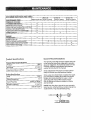
CUSTOMI_R RESPONSIBILITIES
MAINTENANCE
TABLE
l Before each use ]hours
iEvery oryeady
2s
TASK
hours or yearly
Ihou.ro iyeartY
PRESSURE WASHI-_R
_k
h|gh pressure hose.
Oh'_l< soap and ohemlEalh0se and htter
Check gun-andS&ha for t_-k_,=]
Purge pump of'air55a 'cen_mmants
"
Ch_fige pump oil
ENGINE
X
x
x
x
X
..........
X
x
ChbRge engine oil
Clean a i_ er&-a
n_ir ana_recteaner
w
X
-
X
:_roduct
Pressure Washer Specifications
Pressure
Flow Rate
_g
General
Specifications
Units (psi x GPM)
......... 2GOo
2.7 GPM
7020
Rated Horsepower
Spark Plug Gap
Gasoline Capacity
The warranty of the high pressure washer does not
cover items that have been subjected to operator
abuse or negllgenc& To reoeive full value from the
warranty, operator must maintain high pressure
washer as instructed in this manual
Some adjustments will need to be made periodocally to maintain your high pressure washer.
Engine Specifications
RPM
Recommendations
Once a year you should clean or replace the spark
ptug and clean or replace the air filter and check
the gun and wand assembly for wear. A clean
spark plug and clean air filter assure proper
fuel.air mixture and help your engine run better
and last longer°
3600
6.5
0.030" {0o76mm)
3 Quarts
NOTE: Overtime the o-rings in the gun
aGwoTgh(become worn, Attached to your owners
assembly
manual is a
replacememt o-ring and split backup ring,
O-RING
12
•
Pressure
Washer
Maintenance
• Pull the trigger on the gun and hold
Check and Clean Inlet Screen: Examine inlet screen
on pump inlet fitting. Clean if clogged replace if torn.
= _Afnenthe water supply is steady and constant,
disengage trigger and refasten the wand extension.
Check High Pressure Hose: High pressure hose can
develop leaks from wear, kinking, abuse. Inspect hose
each time before use. Check for cuts, leaks, abrasions
or bulging of cover, damage or movement of couplings.
If any of these conditions exlst, replace hose
immediately,.
Engine
Maintenance
oil
Check Chemical/Soap
Hose: Examine the chemical/
soap hose and clean if c{ogged, Hose should fit tightly
Dn pump fitting, Check for leaks and tears.. Replace
filter or hose if either is damaged.
• Oil level should be checked prier to each use
or at least every 5 hours of operation° To check oil see
Adding Engine Off on page 9.
Check Gun and Wand; Examine hose connection to
gun making sure it is secure. Test trigger by pressing it
and making sure it springs back into p{ace when you
release iL
Changing
Pump
Engine
Oil
For a new engine, change oil after the first 5 hours of
operation. Thereafter, change oil after every 50 hours of
operation,
Change the oil while the engine Jsstill warm. The oil will
flow freely and carry away more impurities. Make sure
the engine is level when filling, checking, or changlng oil.
Oil
Pump oil level should be checked before each use,
Change the oil as foItows:
Changing
Pump
. To keep dirt, grass, etc., out of the engine, clean the
area around the drain plug and oil plug before
removing it.
Oil
Oil should be changed after the first 10 hours of operationo Subsequent changes after each 50 hours of operation. To drain oi!, simply remove oi! plug with a adjustable wrench. The oil plug is located at the bottom of the
pump, Dispose of used oil. Property remove pump oil fill
plug.. Add 30 weight non-detergent oil Fill until oil level is
at the mid point on the sight glass.
Purge
Pump
• Remove the oil drain plug and oil plug, Tilt the engine
slightly towards the oil drain to obtain better drainage.
Be sure to allow ample time for complete drainage.
of Air and Contaminants
To remove the air from the pump, follow these steps:
= Set up the pressure washer as described in
Assembly section and connect the water supply.
• Remove the wand extension from the spray gun_
- Reinstall the drain plug. Make sure it is tightened
securely,
° Pull the trigger on the gun and he{d.,
To remove the contaminants
these steps:
from
• Fill the crankcase with new oil of the proper type, to
up to the thread in the oii port, Pour slowly,
the pump_ follow
• Reinstall the oil fill cap or plug and tighten securely.
• Set up the pressure washer as described in
ASSEMBLY section, connect the water supply.
° Remove the wand extension from the spray gun,
• Start the engine according to instructions in the
OPERATION section.
13
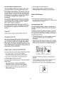
'Cleaning
Pre-Ciean
and Air Cleaner
Catridge
Check
To cleal_ pro-cleaner and air cleaner cartridge wash in
_[_quiddetergent and water. Allow to dry thoroughly
. _eforel using. Do not oil pre-cleanero Replace if very
dirty or damaged.
To service
air cleaner
follow
these
Engine--
Guard/Muffler
Do not clean engine with a forceful spray of water
because water could contaminate fuel system° With
a brush or cfoth clean finger guard after every use tO
prevent engine damage caused by overheating°
steps:
1. Unscrew cover screws, Remove cover, foam pro cleaner, and air cleaner cartridge assembly,,
2. Remove cartiridge from cover, then retainer
(if equipped) and pre-cleaner_
RNGEP,
GUARD
3, To clean pre-cteaner and air cleaner cartridge, wash
in liquid detergent and water. Allow to dry thoroughly
before using Do not oil l;he prec!eaner or cartridge,
Replace if very dirty or damaged..
Before running engine, clean muffler area to remove el!
combustible debris.
NOTE_ Do not use petroleum solvents, e.g., kerosene,
which wilt cause the cartridge to deteriorate., Do not
use pressurized airto clean cartridge. Pressurized air
can damage the cartiridge.
CLEAN
4. Reassemble pro-cleaner or retainer (if equipped.)
Place in cover with pre-cleaner mesh side toward
cartridge. Place cartridge in retainer in cover°
5, Push cover and air cleaner assembly squarely onto
base (tabs must be in slots, tf equipped) and hold
firmly° Tighten cover screws securely.
Clean
and Replace
Spark
Plug
Change the spark plug every 100 hours of operation or
once each year, whichever comes first. This will help
your engine to start easier and run better,
.030" (o.7_MM)
RESISTOR
14
Carburetor
Nozzle
The carburetor of your high pressure washer is pre-set
at the factory. The carburetor should not be tampered
with, If you pressure washer is used at an altitude in
excess of S000 feet consult with your r)earest Sears
Service Center regarding high attitude set changes.
1. Shut off the pressure washer and turn off the water
supply,
2, Disconnect spark plug wire.
3, Pulf triggeron
pressure,
5, Remove the nozzle from the wand. Remove any
obstructions with the nozzle cleaning tool provided
and backfiush with clean water,
6. Direct water supply into nozzle end to back-flush
loosened particles for 30 seconds.,
7", Reassemble the nozzle to the tanoe using teflon tape
to prevent leaks, Tighten securely,.
A WARNING: High engine speeds are dangerous and
increase the risk of personal injury or damage to
..........
_equipment.
8., Reconnect wand to gun and turn on water supply,
9, Start pressure washer and place wand into high
pressure setting to test.,
_k WARNING: Low engine speeds impose a heavy
load on the engine and when sufficient engine
power ls not available could shorten engine life_
Pressure
Washer
Place rag over spark plug hole and pull the recoil a
few times to lubricate the combustion chamber,
for Storage
NOTE: If yot_ do not plan to use your unit for 30 days or
- more, unit should be prepared for storage.
Replace the spark plug, but do not connect the spark
plug wire,
lt4PORTANT: tt is importa_nt to prevent gum deposits
from forming in essential fuel system parts such as the
carburetor, fuel filter hose or tank during storage. Also,
experience indicates that alcohol-blended fuels (called
gasoho) or using ethanol or methanol) can attract moisttjre which leads to separation and formation of acids
during storage, Acidic gas can damage the fue_system
of an engine whi}e in storage, To avoid engine problems,
the fuel system shouid be emptfed before storage of 30
days or longer, Never use engine or carburetor cleaner
products in the fuel tank or permanent damage may
occur,
Engine
gun handle to relieve any water
4.. Disconnect the wand/Jance from the gun_
Zk CAUTION; Engine speed was properly adjusted
at the factory and should require no additional
adjustment., Do not attempt to change engine
speed, if you believe the engine is running too fast
or too slow, take your pressure washer to a Sears
Authorized Service Center for repair and adj[jstment,
Preparing
Maintenance
Pump
Preparation
This pressure washer should be stored in such a way to
protect it from freezing, Do not store this unit outdoors
or In an area where temperatures will fall below 32 ° E
This can cause extensive damage to this unit.
If unit has to be stored under freezing conditions a nontoxic RoV,anti-freeze can be used to protect from
freezing,
• Be sure engine switch is in "OFF" position and spark
plug wire has been removed from spark plug,
Pull the trigger on the spay gun to release the
pressure in the high pressure hose, Detach high
pressure hose and garden hose from the unit.,
Preparation
• First add a fuel stabilizer to the fuel tank,
- Run pressure washer for full 5 minutes to allow fuel
stabilizer to enter the fuel system,
Pull the recoil on the engine 4 to 6 times to discharge
remaining water in pump,
NOTE; While doing this procedure
make sure water
supply is turned on and flowing to the unit., NEVER run
unit without water supply running through pump.,
Tip the unit on the end w_th the water inlet fitting
potnting upward,
• Next shut off engine and disconnect
- Disconnect
plug,
the water supplyo
the spark plug wire and remove
° Add one teaspoon
of oil through
Pour approximately 1/4 cup of non-toxic RV., antifreeze down the fitting where the water hose attaches
to the pump,
the spark
the spark
piug
Set unit upright and put! starter handte on engine 4 to
6 times to circulate anti-freeze in pump until antifreeze is d;soharged from the pump,
hole.
15
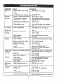
SYMPTOM
CAUSE
SOLUTION
Engine won't
start
1,,
Engine throttle is in "OFF" Position,
2. Choke lever has net been placed to
choke,
1, Slide throttle to "Rabblt" position,
2. Slide choke lever to choke position,
3, Pressure buildup
3, Depress trigger gun°
Won't Draw
Chemical
after initial use.
1. Nozzle not in chemicar draw position,
2_ Chemical screen is obstructed.
3, Chemical
screen not working,
4o Chemical
injector orifice obstructed
1_ Place nozzle to low pressure,
2, Check chemical screen; clean if obstructed
3. Make sure chemical screen is submerged in
chemical/water.
4. Check end clean.
or stuck,
5o Chemical
Pump running
normally but
pressure does
not achieve
rated values
injector closed.
5. Open chemical injector by turning
knob.
1. Water supply restricted,
t,
2. Nozzle is in low PSi position.
2- Twist nozzle at end of wand clockwise the hlgh
pressure position.
3, Check and replace.
4. Check that hoses and fittings are airtJghL
5, Clean nozzle.
3, Nozzle incorrect or wom,,
4, Pump sucking air,
5o Nozzle blocked.
Fluctuating
Pressure
1. Pump sucking air.
2.
3.
4,
5.
hose.
1. Nozzle clogged, partially
obs_ctedo
noisy
2o Nozzle worn,
1, Water too hot,
of
Maintenance
or replace.
and replace.
and replace,
4. Check
and replace if necessary,
I, High humidity.
2, Piston packing and oil seal worn,
1, Change Oil,
2. Check and replace oilseals,
Water dripping
from pump
I, Thermal relief functioning normal,
2. Fittings Loose,
3. O-rings of piston guide or retainer
worn°
4. Piston packing worn.,
1. Protecting pump, if not using pressure
a tong period oftime, shutoff engine.
2. Tighten.
3. Check and replace,
4o Check and replace.,
Oil Dripping
1.
water in oil (oil
milky),
2
(See
under Service Adjustment,)
1, Reduce temperature below 630 C or 145 ° Fo
2, Check that hoses and fittings are airtighL
3. Check, ciean or replace,
2., Pump sucking air.,
3, Valves dirty or womo
4. Worn bearings.
Presence
1, Use nozzle cleaning kit to clear obstruction.
Nozzle
2. Clean
3, Check
44 Check
3. Pump Valves worn, dirty or stuck.
4, Worn pump piston packing,
Pump
Check water supply and filter screen for,
blockage. Check hoses for blockage, kinks,
leaks, etc.
1. Check that hoses and fittings are air tighL Purge air
from garden hose,
2. Clean. Check fitter frequently.
3., Check and replace.
4, Check hose for kinks,
5. Check flow available to pump,, Check for
excessive heat, 145° F or above.
6, Clean inlet and discharge valve assemblies,
Replace if damaged,
Garden hose inlet strainer clogge&
Worn Seals or Packing.
inadequate water supply,
Fouled or dirty inlet or discharge
valves.
6. Leaky discharge
Pressure drops
after period of
normal use
adjustment
Oilsealworn
Loose drainplugorworn dra]n plug
o-ring.
washer
for
1, Check and replace
2, Tighten drain plug or replace o,.ring Do not over torque,
16
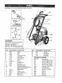
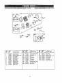
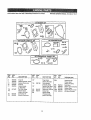
CRAFTSMAN
2600 PSi HIGH PRESSURE WASHER
9t9.769020
9
13
6
900
(Not Included
919..76430
919,76431
9'19,76450
919,76451
with
Pressure
Washer)
Floor/Siding, Brush
Fixed Brush
25Ft, 3/8" high pressure hose
50FL 3/8" high pressure hose
)
17
KEY#
PART NUMBER
DESCRKPTtON
K_(#
PART NUMBER
DESCRIPTION
1
2
3
4
5
6
7
8
9
lO
!1
12
13
9oo
17597
C042
15496
17624
16371
17712
F469
t7720
AL-65OO15
H100
17648
15tll
17600
Handle
Knob
Gun
Tire Semi-Pneumatic
Foot Rubber
Screw HAC 5/16"
Lock Nut 5/16"
Frame
O-dn9 Kit
Chemicat Hose
QC Lance
High Pressure Hose
Decal Front Craftsman
Engine (Refer to Engine Breakdown
Briggs #121432,_0112-E1)
Decal Operation
Pump
High Pressure QG
Adapter- Garden Hose
Nut Pal 1/2"
Screw Hex HDO
22
23
24
25
Ft19
F078
Fl12
17367
Hex Nut
Lock Washer
Flat Washer
Handle Grip
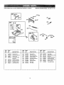
14
15
16
17
18
19
16727
PK16642
F035
16829
F464
F064
]7
MGP*769020
F078
Owners Manual
Lockwasher,Engine to Frame
F11g
Nut Hex '3t16 Engine to Frame
F086
Screw 5116 Engine
to Frame
F107
Lockwashet..Pump
to Engine
18167
Stew, Rex- Pump toEngine
FO?B
Lockwasher- Pump to Engine
NCTO01
Nozzle Cleaning Kit
QC Socket for HP Hose
F039
17732
16927
16928
NoZzle KII0, 2S, 40 Soap
Nozzle 0°
16929
Nozzle 15°
Nozzle 25 °
16930
Nozzle 40 °
16931
NoZzle Soap
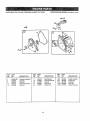
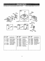
CRAFTFMAN
2600 PSi HIGH PRESSURE
WASHER 919,769020
PUMP BREAKDOWN
MODEL
PK16642
PA _ r(_u_G a._;w
tl
15
t3
/
/
_6
37
3a
c
F
_€= 20_'6
¢
18
CRAFTSMAN
RE_
NO_
I
2
3
4
5
6
7
8
g
10
11
12
13
14
t5
16
17
18
19
20
21
22
2600 PSi HIGH PRESSURE WASHER
PART
NO.
919.769020
PUMP BREAKDOWN
QTY,
NO.
P/_T
NO.
DESCRIPTION
QTY.
O-Ring
Plug
Complete valve
O-Ring
Plug
Support ring
Gasket
Piston guide
Pump body
Cap
Circlip
Snap ring
Bearing
Oil cap
Piston p{n
O-Ring
Screw
Complete cover
Oon rod
6
6
6
6
1
3
3
3
1
1
1
1
1
!
3
1
6
1
3
23
24
25
27
AR-1780070
AR-1260100
AR-1260t10
AR-740290
P)ston
Piston washer
Nut
O-Ring
3
3
3
2
AR-880530
AR-1260460
AR-1780100
AR-770260
AR-1260440
AR-!780380
AR-r1381550
AR-680570
AR-,1321190
AR-1321080
AR-480671
AR=180030
AR-820440
AR-1789200
Guiding piston
O-Ring
Spacer disc
3
3
3
28
30
31
32
33
36
37
38
4O
41
42
44
67
68
69
7O
71
72
73
PJ_,
DESCRIPTION
AR-960160
AR-1260162
AR-1269050
AR-880830
AR-620301
AR-1780130
AR-t260130
AR-1780090
AR-1780010
AR-1266740
AR-1260790
AR-1780550
AR-1780490
AR-880130
AR-1780050
AR-1780510
AR-1200430
AR-1789010
AR-1780040
AR-1780060
AR-480480
AR-1260091
AR-1_AR.,178059_
16747
AR-2973
16506
Plug
Seal
Rear Piston guide
O-Ring
Gasket
H_ead
Washer
Screw
Bearing
Snap ring
Seal
Screw
Grub screw
Pump head pro-ass,
Gas engine flange
Holtow shaft _"
Chemical Injector
Unloader
Thermal Relief Valve
PARTS KITS
A=KIT 16739
Valves
B-KIT 16746
Pistons
Pos,
3
4
23
C=KIT 16748
Oil Seals for
D Version
Pos. Qty.
6
6
10
t6
3O
42
3
t
1
3
1
D=KIT 16745
Water Seals
F=KIT 16749
Bearings
G=KIT 16747
Injector Kit
H=KIT 16744
Unloader O-Ring
Kit
Pos.
Pos_
Pos, Qty.
Pos,
7
32
33
PK16642
Oty,
3
3
3
13
40
Qty,
71
1
1
lg
1
Qty,
2
3
3
3
3
1
8
8
1
1
1
4
1
1
1
1
1
i
1
CRAFTSMAN
2600 PSi HIGH PRESSURE
WASHER 919,769020
BRIGGS ENGINE MODEL #121432-0112-E1
529
12
17
2
RER
NO.
PART
NO.
t
69oo4s(P)
2
3
!2
15
399269
692266
692549
691696
- RE .
"
DESCRIPTION
REF, PART
NO. NO.
DESCRIPTION
NO,
NO.
DESCRIPTION
Cylinder Assembly
Bushing
SesI-OJl
Gasket-Crankcase
P{ug-Oil
17
18
20
2t
22
Bearlng_Batl
Cover_Crenkcase
Seal-Oil
Cap-Oil Fill
Screw-Hsx.
306
307
529
1019
t058
692552
690345
692S63
B90035
273700
Shield-Cylinder
Screw-Hex,
Grommet
Label Kit
Owner's Manual
692510
BgDD47
692550
e92261
592551
2O
CRAFTSMAN
2600 PSI HIGH PRESSURE WASHER
919,769020
BRIGGS
ENGINE
MODEL
#121432-Olt2-E1
.............
" ....i
REF. PART
NO,
NO,
5
7
11
t3
33
34
35
40
45
51
124
499922
692554
692600
691137
499642
_99641
691304
692194
690977
692555
692568
DESCRIPTION
Head-Cylinder
Gasket-Cylinder Head
Tube-Breather
8crew-,Hex.
Valve-Exhaust
Valve4ntake
Spring-Valve
Retainer-Valve
Tappet-Valve
Gasketqntake
Screw-He×,
RER
NO.
PART
NO.
155
189
238
3O5
305A
337
353
383
635
83O
692556
591295
691300
691108
692557
690968
692558
1937a
692186
692559
DESCRIPTION
REF, PART
NO, NO.
DESCRIPTION
868
978
1022
t023
1026
1029
1034
Seal-Valve
Gasket-Plate
Gasket-RockerCover
Cover-Rocker
Rod-Push
Arm-Rocker
Guide-Push Rod
__
Plate-Cylinder Head
BatFRockerArm
Cap,,Valvs
Screw-Hex,
$crew-Hex,
PlugoSpark
Nut-Nex,
Wrench-Spark Plug
Boot-Spark Plug
Screw*He_.
21
692044
691892
69t890
498924
692560
691230
691343
.............
..........
,,,
CRAFTSMAN 2600 PSI HIGH PRESSURE WASHER 919,769020
BRIGGS ENGINE MODEL #121432.,0112-E1
742
26
_':,l
_
---
I L[II,
RER
NO.
PART
NO,
DESCRIPTION
16
17
24
25
26
27
28
692561
692510
690974
499627
499631
691866
499423
Crankshaft
Bearing-Bail
Key-Flywheel
Piston Assembfy
Ring Set
Lock-Piston Pin
Pin,.Piston
--
RER
NO,
PART
NO,
DESCRIPTION
29
30
32
46
690124
692562
691664
692563
Rod-Connecting
Dipper"Connecting Rod
Screw.Connecting Rod
Gear-Cam
22
R_SR PART
NO, NO.
DESCRIPTION
146
219
220
741
742
743
Key-Timing
Gear"Governor
Washer.Thrust
G_ar.Timing
Ring-Retaining
Gear-Idler
690979
692418
691724
692565
692564
692566
CRAFTSMAN
2600 PSI HIGH PRESSURE WASHER 919,769020
BRIGGS
ENGINE
MODEL
#121432-0112-Et
[
|
, 634A
11!Ill
18s
_e
f
_ZL,,'//m130
95
REF.
NOo
PART
NO,
51
692555
95
98
104
108
110
691636
398185
691242
6925S7
!I1
590572
DESCRIPTION
Gasket-Intake
(2 Required)
ScreW-Slotted
Screw-fdle Speed
Pin.Float Hinge
Vaive.,Choke
Washer-Seal
(Sold in Kit Only)
Spring-Friction
(Choke)
RE[F,
NO.
PART
NO.
117
122
127
690048
690043
130
t3I
133
134
69't181
699024
398187
398188
!
J
t
DESCRIPTION
Jet-Main (Standard)
Spacer*Carburetor
Plug-Welch
(Sold in Kit Only)
Vatv_-Throttfe
Shaft-Throttle
Float-Carburetor
Valve-Needle
:: ----
......
,_
......
.........
REF. PART
NO, NO.
137
141
163
786
634
699023
691887
692317
634A
975
23
......,
493640
DESCRIPTION
Gasket-Float Bowl
(Sold in Kit Only)
Shaft-Choke
Gasket-Air Cleaner
Connector-Hose
Washer
(Sold inKit Only)
Washer
(Sold in Kit Only)
Bowl.Float
CRAFTSMAN
2600 PSI HIGH PRESSURI_ WASHER 9! 9.769020
BRIGGS
ENGINE
MODEL
#1_!432oOl12-E1
2tl
281
232
....
RER
NO.
PART
NO,
75
98A
1B8
202
495659
493280
590877
692569
209
211
222
227
692569
691796
692572
692573
DESCRIPTION
RER
NO,
PART
NO.
DESCRIPTION
Washer Set
Screw-Idle Speed
Screw-Hex.
Link-Mechanical
Governor
Spring-Governor
Spring-Governor
Bracket-Control
Lever-Governor
232
265
267
2B1
333
334
347
354
356
692570
691024
690804
692574
692605
691061
692599
692575
692602
Spring-Link
ClampoCasin9
Screw-Slotted Hex.
Panel-Control
ArmBture-Magneto
Screw.,Hex,
Swltch-Rocker
Nut.Lock
Wire.Stop
24
--
......
.J.J,,,,u
RER
NO.
PART
NO.
DESCRIPTION
356A
562
592
615
6t B
663
843
851
692603
6911 t2
691251
692576
692547
692577
692578
493880
Wire-Stop
Bolt.Governor Level
Nut-He=:_
Retainer-Governor
Cratlk-Governor
Screw._Slotted Hex.
Sleeve_Lever
TerminaI-C_bte
CRAFTSMAN
2600 PSI HIGH PRESSURE WASHER
91&769020
BRtGGS
ENGINE
MODEL
#121432-0112-E1
957
6421
967
535
%
176
971
......
......
..
lu
......
346
_ ......
863A
RER
NO.
PART
NO.
161
163
t76
167
692579
691887
692127
298049
!87A
298
300
892601
690453
692580
DESCRIPTION
Base-Air Cleaner
Gasket-Air Cleaner
Screw.Shoulder
Line-Fuel (Cut to
Required Length)
Line-Fuel ('Molded)
Lecknut-Mu ft"ter
Muffler-Exhaust
RER
NO.
PART
NO,
DESCRIPTION
346
346A
373
526
534
535
601
642
8!9
832
690681
692581
692582
691127
692583
691710
692201
692584
692598
692584
Screw-Hex
Screw-He×_
Nut-Tinnerman
Screw_Hez,
Screw-Stottee Hex,
Filler-Air
Cramp.Hose
Cover-Air Cleaner
Screw-Hex,
Guard-Muffler
28
=_
819
RER
NO.
PART
NO,
DESCRIPTION
863
863A
864
957
958
987
971
972
692595
692596
682548
691654
692586
691706
691106
692587
Bracket-Muffler
Bracket.Muffler
AdaptePMuffler
Cap-Fuel Tank
Valve-Sht_toff
FRet-Air (Pre-Fitter)
8crew-Shoulder
Tank-Fuel
CRAFTSMAN 2600 PSI HIGH PRESSURE WASHER 919,769020
BRIGGS ENGINE MODEL #'_21432-0112-E1
23
1005
305 _
RER
NO.
PART
NO,
DESCRIPTION
RER
NO.
PART
NO.
DESCRIPTION
RER
NO,
PART
NO.
DESCRIPTION
23
65
188A
692588
692608
692590
FlywheCt
Screw-Hex,
Screw-Shoulder
304
305
332
692569
69110B
690662
Housing-Biower
Scr_w-Hex.
Nu|..Flywheel
363
455
1005
19069
692591
692592
Flywheel Puller
Cup-Flywheel
Fan-Flywheel
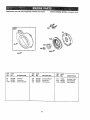
26
CRAFTSMAN
BRIGGS ENGINE MODEL #121432_01_2-E1
2600 PSI HIGH PRESSURE WASHER 9t9.769020
689
373A
6sA _P
REF. PART
NO.
NO,
55
891422
56
58
498144
692593
59
592594
DESCR{PTION
Housing-Rewind
Starter
P[_lley-Starter
Rope,,Starter {Cut To
Suit)
insert-Grip
REF,
NO.
PART
NO,
DESCRIPTION
SO
6DA
65A
373A
456
393152
691 g3D
690837
690800
692299
GripStart_r Rope
Grip-Sta_ler Rope
Screw-H_x,
Nut-He×,
Retainer-Spring
27
RER
NO,
PART
NO.
DESCRIPTION
459
608
623
689
692260
497830
691696
691855
Paw_.Ratchet
Starter-Rewind
Screw.Shoutder
Spring.Friction
CRAFTSMAN
2600 PS! HIGH PRESSURE WASHER
919.769020
=--- -....... = "..............35BeAS__"
SET :
:::-_3
_,
_=
,
...... ::_
......
:_;
BRIGGS
ENGINE
MODEL,
#;2!€32-0112-EI
................
".........
.....................
.......
:.::;
1033 VALVE OVERHAUL
KiT
634
634A_
70
lz
!10_
lz;,_
_..
....
...
::__,
,_
[70 ,.,.
RER
NO,
--
PART
NO.
=
DESCRIPTION
RER
NO.
PART
NO.
IDES_RIPTION
.
3
7
12
20
51
692266
692554
692549
692550
692555
104
ti0
691242
12t
t22
690032
590043
Seal-Oil
Gasket,Cylinder
Head
Gasket.Crankcase
SeaI-Oit
Gasket-Intake
(2 Required)
Pin.Float Hinge
Washer-Seal
(Sa{d in Kit On_y)
Carburetor Kit
Spacer-Carburetor
t27
t 34
398168
137
163
358
634
691887
69003't
Plug-Welch
(Sold in Kit Only)
Valve-Ne_dfe
(Includes Seat)
Gasket-Float Bowl
(Sold in Kit Only)
Gasket-Air Cleaner
Gasket Set
Wa_her-_;haft
(Throttle Shaft)
(Satd in Kit Only)
28
RER
NO,
PART
NO,
DESCRIPTION
692044
690033
691882
691890
690034
Washer-Shaft
Choke Shaft
(Sold in Kit Only)
Seal.Valve
Gasket Set-Carburetor
Gasket-Plate
Gasket-Rocker Cover
Kittva_ve Overhaul
634A
868
977
976
1022
1033
29
Br_ggs & Straiten welcomes warranty repair and apologizes
to yoU for being inconvenienced.
Any Authorized Service
Dealer may perform warranty repairs, Most warranty repairs
are handled routinely, but sometimes requests for warranty
service may not be appropriate. For example, warrantywould
not apply if engine damage occurred because of misuse, lack
of routine maintenance, shipping, handling, warehousing or
improper Installation, S}milady, warranty is void if the serial
number of the engine has been removed or the engine has
been altered or modified..
4.
&
Repalr or adjustment of associated parts or assemblies
such as clutches, transmissions,
remote controls, etc,
which are not manufactured by Briggs & Stratton.
6, Damage or wear to parts caused by dirt, which erltered
the englne because of improper air cleaner maintenance,
re-assembly, or use of a non-original air cleaner elemenl
or cartridge. (At recommer{ded Intervals, clean and re.oil
the Oil-Foam® element or the foam pro-cleaner,
and
replace the cartridge.) Read "Owner's Manual,"
If a customer differs with the decision of the Service-Dealer, an
investigation will be made to determine whether the warranty
applies. Ask the Service Dealer to submit all supporting facts to
his Distributor or the Factory for review. If the Distributor or the
Factory decides that the claim is justified, the customer wtll be
fully reimbursed for those items that are defective.. To avoid
misunderstanding
which might occur between the customer
and the Dealer, listed below are some of the causes of engine
failure that the warranty does not cover.
Improper
7,
Parts damaged by overspeeding, or overheating caused
by grass, debris, or dirt, Which plugs or clogs the cooling
fins, or flywheel area, or damage caused by operating the
engine tn a confined area without sufficient ventilation.
(Clean fins on Ihe cylinder, cy[inder head and flywheel at
recommended intervals_) Read "Owner's Manual,"
& Engine or equipment parts broken by excessive vibration
caused by a loose engine mounting, loose cutter blades,
unbalanced blades or loose or unbalanced
impellers,
imprDpar attachment ofequipment to engine crankshaft,
overspeeding or other abuse 11"toperation._
meinter=ance'
The life of an engine depends upon the conditions under
which it operates, and the care it receives, Some applications,
such as _lers, pumps and rotary mowers, are veryoften used
in dusty or dirty conditions, which can cause what appears to
be premature wear.. Such wear, when caused by dirt, dust,
#park plug cleaning grit, or other abrasive materiat that has
• entered the engine because of improper maintenance, isnot
covered by warranty,
9._ A bent or broken crankshaft, caused by striking a solid
object with the cutter blade of a rotary lawn mower, or
excessive v-belt tightness.
t0. Routine tune-up or adjuslment of th_ engine.
11. Engine or engine component fat)ure, i.e., combustion
chamber, valves, valve seats, valve guides, or burned
starter meier windings, caused by the use of alternate
fuels such as, tiquified petroleum, natura} gas, altered
gaso{ines, etc.
This warranty covers engine related defective material
and]or workmanship._KLw and not replacement or refund
of the equipment to which the engine may be mounted.
Nor does the warranty eztend to repairs required
because of;
1.
PROBLEMS
CAUSED BY PARTS THAT
ORIGINAL BRIGGS & STRATTON PARTS,
ARE
2.
Equipmenl controls or installations that prevent starting,
cause unsatisfactory
engine performance, or shorlen
engine life. (Contact equipment manufacturer.)
5,
Leaking carburetors, dogged fuel pipes, sticking valves,
or o_her damage, caused by using contaminated or state
fuel.. (Use clean, fresh, lead-free gasoline and Briggs &
Stratton gasoline stabiIizer. Pan No, 5041o)
Parts which are scored or broken because an engine wa_
operated with insufficient or contaminated lubricating oil,
or an incorrect grade of lubricating ott (check oil level daily
or after every B hours of operation. Refill when necessary
and change at recommended intervals_) Read "Owner's
Manual"
NOT
3O