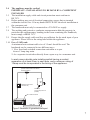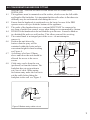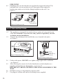
1
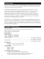
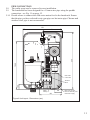
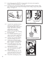
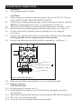
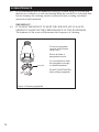
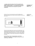
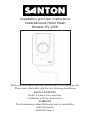
Multipoint
Installation and User Instructions
Instantaneous Hand Wash
Models: EV 2008
Please read and understand these instructions before starting work.
Please leave this leaflet with the user following installation
PACK CONTENTS
Heater, Fixing screws and plugs,
Installation and User Instructions.
WARNING
This Instantaneous Hand Wash must only be installed by
qualified persons.
36006008 Issue 3. 1
INTRODUCTION
Thank you for purchasing a Santon EV2008 Handwash. The Handwash instantaneous
water heater is manufactured to the highest standards and has been designed to meet
all the latest relevant safety specifications.
This Handwash instantaneous water heater must be installed (Sections 4.0-7.0),
commissioned (Section 7.0) and maintained (Sections 8.0 - 9.0) by a competent
person. Please read and understand these instructions prior to installing your
Handwash instantaneous water heater. Particular attention should be paid to the
section headed SAFETY (section 2.0). Following installation and commissioning
the operation of the heater should be explained to the user (Section 7.0) and these
instructions left with them for future reference.
This appliance is not intended for use by persons (including children) with reduced
physical, sensory or mental capabilities, or lack of experience and knowledge, unless
they have been given supervision or instruction concerning the use of the appliance by
a person responsible for their safety. Childern should be supervised to ensure that they
do not play with the appliance.
TECHNICAL SPECIFICATION
2
CONNECTIONS
Inlet connection -15mm ext. diameter (copper or push fit stem elbow)
Water entry point - bottom and rear
Cable entry point - bottom and rear
ELECTRICAL
Model numbers 3.1kW - Handwash - 94 020 015
7.2kW - Handwash - 94 020 016
Electrical rating...........................................................................2.8/3.1kW @ 230/240V
.....................................................................................................6.6/7.2kW @ 230/240V
Ampre rating...............................................................................2.8/3.1kW @ 2.4/12.9A
.....................................................................................................6.6/7.2kW @ 8.75/30A
MATERIALS
Backplate, cover and control knob- ABS
Element(s) - Copper sheathed rod type.
DIMENSIONS
Height - 235mm
Width - 151mm
Depth - 85mm
STANDARDS AND APPROVALS
Complies with the requirement of EN 60335-2-35.
British Electrotechnical Approvals Board (BEAB) approved.
Complies with European Community Directives (CE).
Thermostat
Thermal
cut-out
Pressure switch
Front
cover
Flow control valve
To close: turn
anticlockwise
Multipoint
1.0 INTERNAL COMPONENTS
1.1 A pressure relief device (PRD) is designed into the handwash appliance, which complies with European standards. The PRD provides a level of appliance protection should an excessive build-up of pressure occur within the appliance.
1.2 DO NOT operate the handwash with a damaged spout or blocked sprayplate, which can cause the PRD to operate.
Rating label
Inner
container
Terminal block
Cable clamp
Outlet spout
Pressure relief device (PRD)
Spout fixing nut
Sprayplate
Figure 1 Internal components - 3.1kW
(refer to fig.2 page 6 for 7.2kW )
2.0 SAFETY
2.1
2.2 2.3
IMPORTANT INFORMATION
Products manufactured by Santon are to British and European Standards. These appliances are safe and without risk, provided they are installed, used and maintained in good working order in accordance with our instructions and recommendations.
Please read and understand these instructions before starting work and retain them for later use.
DO NOT operate the appliance if it is frozen, or suspected of being frozen. See fault finding table.
3 3
2.4
2.5 2.6 2.7 2.8 2.9 2.10 2.11 2.12
2.13
2.14 2.15 2.16 2.17 2.18 2.19 4
DO NOT operate the appliance if:
1. Water ceases to flow during use.
2. Water has entered inside the unit because of an incorrectly fitted cover.
3. If the appliancet is damaged.
ISOLATE the electrical and water supplies before removing the cover.
ISOLATE the electrical and water supplies BEFORE proceeding with installation or servicing.
The appliance must be mounted on to a flat finished wall surface that covers the full width and length of the backplate (or on top of the tiles).
DO NOT tile up to the appliance after fixing to the wall.
The sprayplate must be cleaned when any of its holes become blocked, otherwise restriction to the flow from the outlet spout will result in higher temperatures and could also cause the pressure relief device in the appliance to operate - see 1.1 and 10.2.
The product is NOT SUITABLE for mounting into steam rooms or steam cubicles.
The installation must be carried out in accordance with the relevant requirements of: • The appropriate Building Regulations either The Building Regulations, The Building Regulations (Scotland) or Building Regulations (Northern Ireland).
• The Water Fittings Regulations or Water Byelaws in Scotland.
CAUTION
It is recommended that persons who may have difficulty understanding or operating the controls should not be left unattended whilst washing hands. Special consideration should be given to young children and persons with reduced physical, sensory or mental capabilities.
Only use designated entry points for cable and pipe.
PLUMBING
The plumbing installation must comply with Water Regulations.
The supply pipe must be flushed to clear debris before connecting to the handwash appliance.
DO NOT solder pipes or fittings within 300mm once the pipework is located in the appliance, as heat transfer can damage components.
DO NOT fit any form of outlet flow control, as the outlet acts as a vent for the heater can.
DO NOT use excessive force when fitting the spout fixing nut, finger tightness is sufficient.
All plumbing connections must be completed and checked for leaks before making the electrical connections.
ELECTRICAL
Before fitting the appliance, ensure that the consumer unit and any switches are suitable for the additional load. If in doubt, contact your electricity supplier or a qualified electrician.
The installation must comply with BS 7671 ‘Requirements for electrical
installations’ (IEE Wiring Regulations).
2.22 2.23
2.24
2.25 2.26 CAUTION
This appliance must be earthed.
Fuses do not give personal protection against electric shock. To enhance electrical safety a 30mA residual current device (RCD) should be installed in all electric handwash circuits. This may be part of the consumer unit, or a separate unit.
Ensure that all terminal block connections are sufficiently tight.
Switch off appliance immediately and isolate if water ceases to flow during use.
Other electrical equipment e.g. extractor fans, must not be connected to the handwash or its supply circuit.
Multipoint
2.20 2.21 5
5
3.0 SITE REQUIREMENTS
WARNING
3.1 The handwash must not be positioned where it will be subjected to freezing conditions.
3.2 3.3 WATER REQUIREMENTS
The installation must be in accordance with Water Regulations. To ensure activation of the heating elements, the handwash must be connected to a mains water supply with a minimum running pressure of 0.1 MPa (1 bar) and a maximum static pressure of 0.7 MPa (7 bar). If static pressure exceeds 0.7MPa (7bar) fit a pressure reducing valve to avoid damaging the appliance.If in doubt, the pressure should be checked taking account of other services from the same water supply which could cause the pressure to fall below the minimum. The water supply can also be taken from a cold water storage cistern provided there is a minimum head of 10m above the appliance.
If the handwash is operated outside of the stated pressure parameters, it may not be possible to achieve optimum performance from the appliance throughout the year.
ELECTRICAL REQUIREMENTS
WARNING
red
red
red
red
red
Inner
container
red
7.2kW
Terminal
block
Figure 2 Wiring diagram
6
black
Cut
Out
Presure
switches
Cut
Out
green/yellow
red
black
Inner
container
3.1kW
Presure
switch
red
red
green/yellow
Terminal
block
N
L
N
L
The appliance must be earthed
IMPORTANT - INSTALLATION TO BE DONE BY A COMPETENT INSTALLER
The installation supply cable and circuit protection must conform to BS 7671.
Before making any sort of electrical connection, ensure that no terminal within the circuit is live. If in any doubt SWITCH OFF the whole installation at the consumer unit.
The handwash must only be connected to a 230-240V ac supply.
The earthing and protective conductor arrangement within the property, in particular the supplementary bonding in the room containing the handwash, must comply with BS 7671.
Ensure that the supply cable and fuse are sufficient for the rated input of your appliance. Please refer to the rating label within the appliance.
For a 3.1kW unit:
A minimum heat resistant cable size of 1.5mm² should be used. The handwash can be connected in two different ways.
1. Via a fused and switched connection unit taken as a spur from a 13amp ring main.
2. As a separate circuit taken directly from a spare way in a consumer unit.
In each case a double pole isolating switch having a contact separation of at least 3mm in each pole, and a minimum rating of 13amp must be incorporated in the wiring of the appliance.
Multipoint
3.4 3.5 3.6 3.7 3.8 3.9 3.10 Double pole isolating switch:
pull cord or wall mounted in accordance
with IEE regulations
RCD (can be part of the
consumer unit)
Shower unit
(use rear entry when it is
possible)
800 or 100A main switch
Meter
Consumer unit
Meter ‘tails’
Figure 3 Schematic of typicalelectrical layout
7
7
8
3.11 3.12 To obtain full advantage of the power provided by the handwash, use the shortest cable route possible from the consumer unit to the handwash.
If your consumer unit has a rating below 80A or, if there is no spare fuse way, then the installation will not be straightforward and may require a new consumer unit. A qualified electrician should install the new consumer unit. It may be necessary to contact your electrical supplier to upgrade your supply.
3.13 CAUTION
To enhance electrical safety a 30mA residual current device (RCD) should be installed in all electric handwash circuits. This may be part of the consumer unit or a separate unit. DO NOT use a rewireable fuse, instead use a suitably rated miniature circuit breaker (MCB) or cartridge fuse. The handwash must be connected to its own independent electrical circuit.
Multipoint
4.0 CONSIDERATIONS BEFORE FITTING
IMPORTANT - INSTALLATION TO BE DONE BY A COMPETENT INSTALLER
4.1 The appliance must be mounted on a flat surface, which covers the full width and length of the backplate. It is important that the wall surface is flat otherwise difficulty may be encountered when fitting the cover.
4.2 Ensure that the handwash is positioned over the basin, because if the PRD operates water will eject from the bottom of the appliance.
4.3 The outlet of the handwash acts as a vent and MUST NOT be connected to any form of outlet flow control, or any other fitting not recommended by Santon.
4.4 DO NOT fit the handwash to the wall and tile up to the case. It must be fitted on to a finished flat and even wall surface. This allows removal for servicing.
4.5 The control knob is an integral part of the cover - do not attempt to remove it.
4.6 Position the unit above the Main water supply
(Use rear entry when
200
basin so that the spray will be it
is possible)
mm
contained within the basin and at a convenient height for hand washing 130mm
see Figure 4.
min
PRD
4.7 A clearance of at least 130mm Outlet
above and below the unit should be allowed for access to the cover screws.
Typical arrangement
4.8 Cable entry can be from the rear (preferred) or from the bottom. The Isolating stop valve
backplate has cut-out position to suit size of cable. When opting for bottom entry make the cut-out to Figure 4 Handwash position over basin (or sink)
suit the cable before fitting the backplate to the wall -see Figure 5.
Make cut-out
using sharp
knife
Figure 5 Bottom entry cable cut-out
9
9
4.9 PIPE ENTRY
Plumbing entry can be from the rear (preferred) or from the bottom. The backplate has a cut out position to suit 15mm pipe.When opting for bottom entry make cut out before fitting backplate to the wall - see Figure 6.
Figure 6 Plumbing cut-out
Make cut-out
using sharp knife
5.0 FITTING INSTRUCTIONS
5.1 TURN OFF water and electrical supply.
5.2 The appliance is designed for bottom and rear entries of water and electric cable. It is advisable to use the rear entry (when it is possible), in order to obtain a neater installation.
5.3 Unscrew the retaining screws and lift the cover from the back plate - see Figure 7.
Figure 7 Removing Cover
'O' rings
Plastic nut
(finger tight only)
Outlet pipe
Figure 8 Fitting outlet spout
5.4 5.5 5.6 5.7 10
Fit the outlet spout - DO NOT over tighten, finger tight will be sufficient - see Figure 8.
After choosing the correct site for the handwash, use the backplate as a template and mark the two fixing holes - see 4.1 to 4.7.
BEWARE OF CABLES AND PIPES WHICH MAY BE BURIED IN THE WALL.
Drill holes using a 6.5mm diameter masonry drill.
Use plugs to suit the wall and use the fixing screws supplied.
74
196.5
235
151
Multipoint
PIPE CONNECTION
The outlet spout can be removed to ease installation.
The handwash has been designed for a 15mm water pipe using the pushfit connection - see Fig. 11 on page 12.
Decide where to connect the cold water mains feed to the handwash. Ensure that the pipe you have selected is not a gas pipe or a hot water pipe. Chrome and stainless steel pipe is not recomended.
Inlet water
connection
Terminal
Block
19.5
5.8 5.9 5.10
Cable
Clamp
29
86
Rear entry access
area for electricity and
inlet water supply
Figure 9 Unit layout - Dimensions (mm)
11 11
5.11 5.12 An isolating stopvalve MUST be incorporated to the main water supply to comply with Water Regulations - see Fig. 4.
Cut all necessary pipework to length with a pipecutter and not a hacksaw. This will minimise the swarf and prevent damage to the sealing o-ring in the pushfit fitting - see Figure 10.
35mm
Figure 10 Cutting pipes
Bottom entry
Rear entry
Copper compression fitting
shown - push fit stem
elbow can be used.
Figure 11 Pipe connection
5.13 5.14 5.15 5.16 5.17 5.18 5.19 5.20 5.21 12
Assemble the installation before making any soldered joints to ensure that the pipe is the correct length. DO NOT use jointing compounds on any pipe fittings for the installation.
Remove the unit before soldering the connections.
It is essential to flush the pipe in order to clear debris, particles of solder and swarf - see Figure 12.
Turn the water off after flushing using the isolating stop valve.
Connect the cold water supply pipe to the inlet of the handwash, this is a push fit - see Figure 11.
Fit top and bottom screws and secure the backplate to the wall ensuring that it is level.
Close the handwash flow control valve by turning the gear fully anti-clockwise.
Turn the isolating stop valve on slowly and check for leaks in all pipework, rectify as necessary.
Turn off the isolating stop valve.
Figure 12 Flushing the pipework
close
6.0 ELECTRICAL CONNECTIONS
WARNING
This appliance must be earthed.
Multipoint
6.1 6.2 6.3
6.4 6.5 6.6
6.7 6.8 CAUTION
When working on electrical components ensure they are NOT LIVE. If in any doubt, SWITCH OFF THE ELECTRICITY SUPPLY.
A double-pole isolating switch having a contact separation of 3mm in each pole MUST be incorporated to the circuit - see paragraphs 4.10 and 4.11.
The cable entry should have been decided before fitting the backplate - see 5.8.
Remove the screws and clamping bar from the cable clamp - see Figure 13.
Feed the cable in the backplate (unscrew backplate for easy feeding if neccessary).
Strip the outer sheath of the cable to a point about 5mm above the clamp, thus ensuring that the cable is clamped across its outer sheath.
Strip the insulation from the cores and make connections - see Figure 13.
red or brown to 'L'
green & yellow to
blue or black to 'N'
Cable clamp
Figure 13 Electrical connection
6.9 Make sure that all the terminal block screws are sufficiently tight.
6.10 Refit the clamp bar.
FITTING COVER
6.11 Fit outlet spout if required - see 5.4.
6.12 Check that the flow control valve is fully closed by turning the gear fully anti-clockwise.
6.13 Turn control knob until the indicator is between the START and STOP position.
6.14 Place the cover onto the backplate.
6.15 Secure the cover to backplate using screws provided.
13
7.0 COMMISSIONING
7.1 7.2 7.3
7.4 7.5 7.6 7.7 7.8
14
NOTE: The first operation of the handwash is intended to ensure the heater unit contains water before the appliance is switched on.
Before turning on the electricity and mains water to the handwash, ensure the control knob is turned fully clockwise.
Turn on the main water supply at the isolating stop valve and slowly turn the control knob clockwise, (it will take appoximately 30 seconds for a smoth flow of water to be obtained whilst any air is being dispersed from the handwash).
Stop the water flow by rotating the control knob clockwise.
Turn on the electrical supply at the isolating switch.
Rotate the control knob half a turn anti-clockwise. After approximately 15 seconds, the water will start to heat.
To obtain warmer water turn the control knob clockwise and for cooler water turn anti-clockwise.
Shut off the handwash by turning the control knob clockwise. The appliance is now ready to use.
The neon will illuminate when the water is heating.
8.3 8.4 Multipoint
8.0 FAULT FINDING
8.1 In the unlikely event of a problem, consult the trouble-shooting chart below.
8.2 If you are unable to remedy the problem, CONTACT YOUR INSTALLER in the first instance.
IMPORTANT
Do not attempt any electrical or plumbing work unless you are competent to do so.
If you still cannot solve the problem, please contact Santon.
INSPECTION
8.5 It is advisable that, in the interests of safety, the handwash and its electrical installation is checked by a competent electrician, at least every two years.
SYMPTOM
POSSIBLE CAUSE
A. Water supply turned off
B. Unit frozen
1. No water flows
with valve open
2. Water too cold
3. Water too hot
4. Water runs from
pressure relief
device
C. Spout blocked
D. Filter blocked
A. Water control knob at
wrong setting
B. Water flow too high
C. Electricity off
D. Poor flow
A. Temperature control knob
at wrong setting
B. Spout partially blocked
C. Isolating valve not fully
open
D. Filter blocked
A. Spout blocked
B. Spout not blocked
REMEDY
Turn on water supply
Turn OFF ELECTRICITY at isolating switch
and contact installer. DO NOT USE THE
HANDWASH.
Clean sprayplate - see 10.2
Clean filter
Turn knob clockwise until temperature is
comfortable
Turn knob clockwise until temperature is
comfortable
Turn on electricity at isolating switch
Check inlet pressure
Turn knob fully anticlockwise to increase
flow and lower temperature
Clean sprayplate - see 10.2
Open isolating valve
Clean filter
Clean sprayplate - see 10.2
push plastic plunger up and back in place
Call a service engineer as there may be
a problem with internal parts
15
9.0 MAINTENANCE
9.1
It is recommended that the handwash casing be cleaned using a soft cloth and that the use of abrasive or solvent cleaning fluids be avoided. It is advisable that before cleaning, the isolating switch is turned off, thus avoiding accidental operation of the handwash.
9.2
IMPORTANT
IT IS MOST IMPORTANT TO KEEP THE SPRAYPLATE CLEAN IN ORDER TO MAINTAIN THE PERFORMANCE OF THE HANDWASH. The hardness of the water will determine the frequency of cleaning.
To remove sprayplate
unscrew anticlockwise
using a coin.
Ensure all holes in
sprayplate are clear.
Sprayplate
It is recomended to soak
the sprayplate overnight
in suitable descalant.
DO NOT OVERTIGHTEN
when refitting sprayplate.
Figure 14 Cleaning sprayplate
16
1
2
3
4
Multipoint
Guarantee
This product is guaranteed against faulty materials and manufacture for a period of
two years from the date of purchase provided that:
The unit has been installed by a competent person in accordance with the Installation, User Instructions, all relevant Codes of Practice, Regulations in force at the time of Installation and that all necessary controls and safety valves have been fitted correctly.
Any valves and controls are of the Santon recommended type and specification.
The appliance has not been modified or tampered with in any way, and has been regularly maintained as detailed in the Installation and User Instructions.
The appliance has been used only for heating potable water.
The appliance is not guaranteed against damage by frost, and the inner container with
integral heating element is not guaranteed against excessive scale build-up.
This guarantee in no way affects the statutory rights of the consumer.
The policy of Santon is one of continuous product development and, as such, we
reserve the right to change specifications without notice.
Environmental Information
Santon products are manufactured from many recyclable materials.
At the end of their useful life they should be disposed of at a Local Authority
Recycling Centre in order to realise the full environmental benefits.
17
Notes:
_________________________________________________________
18
Notes:
Multipoint
_________________________________________________________
19
Spares Stockists
SPD
Units 9 & 10 Hexagon Business Centre
Springfield Road, Hayes
Middlesex, UB40 0TY
Tel: 020 8606 3567
Sales Tel:
Sales Fax:
Hurricane Way,
Sales Email:
Norwich,
Service Tel:
Norfolk, NR6 6EA.
Service Fax:
www.santon.co.uk
ServiceEmail:
20
© 2008
(08700) 603263
(08700) 600403
[email protected]
(08701) 600126
(08701) 600181
santonservice@
heateam.co.uk