1
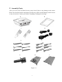
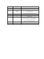
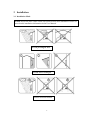
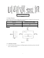
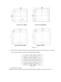
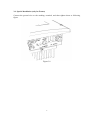
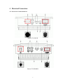
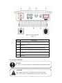
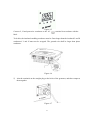
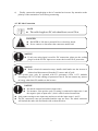
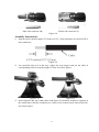
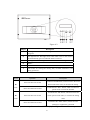
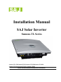
Installation Manual SAJ Solar Inverter Sununo-TL Series Sununo-TL1.5K\Sununo-TL2K\Sununo-TL3KB\Sununo-TL4KB Sununo-TL3KA\Sununo-TL4KA\ Sununo-TL5K Please read this manual carefully before installation. Index 1 2 3 4 5 6 7 Introduction ..................................................................................................................... 1 Assembly Parts................................................................................................................ 2 Installation....................................................................................................................... 4 3.1 Installation Mode .................................................................................................. 4 3.2 Safety Clearance ................................................................................................... 5 3.3 Mounting Procedure. ............................................................................................ 5 3.4 Special Installation (only for France) ................................................................... 8 Electrical Connection ...................................................................................................... 9 4.1 Overview of connection area ................................................................................ 9 4.2 AC Side Connection ........................................................................................... 10 4.3 DC side Connection............................................................................................ 13 Pre-running Inspection .................................................................................................. 16 5.1 DC Side Inspection ............................................................................................. 16 5.2 AC Side Inspection ............................................................................................. 17 5.3 Communication Inspection................................................................................. 17 Operation method.......................................................................................................... 17 6.1 Start SAJ Solar Inverter ...................................................................................... 17 6.2 Key Operation .................................................................................................... 17 Contact SAJ .................................................................................................................. 19 1 Introduction This manual introduces the installation and configuration of below models of SAJ Solar Inverters. Sununo-TL1 .5K\Sununo-TL2K\Sununo-TL3KB\Sununo-TL4KB Sununo-TL3KA\Sununo-TL4KA\ Sununo-TL5K Only qualified electricians who have read and fully understood all safety regulation contained in this manual can install the inverter. Installers must be aware of native regulations, laws and safety requirements. CE Mark Equipments with the CE mark certify are in compliance to the 2004/108/EC and 2006/95/EC. This Installation Manual provides quick installation guidance, but it can’t replace the User Manual. If more detail information is needed, please refer to the User Manual. 1 2 Assembly Parts After you receive the SAJ Solar Inverter, please check if there is any damage on the carton. Please also check the inside completeness and for any visible external damage on the inverter or any accessories. Contact your dealer if anything is damaged or missing. B A C D E F G I G H Figure 2.1 2 I Object Quantity Description A 1 SAJ Solar Inverter B 1 Rear Panel C DC Connector (for Sununo-TL1.5K/2K) 1 Sets DC Connector (for 2Sets Sununo-TL3KB/4KB/3KA/4KA/5K) D 2 RS485Connector E 6 M6×50 Expansion screw F 6 Expansion tube M4×12 Cylinder head screw and Lock G 4 washer(Sununo-TL1.5K/2K/3KB/4KB) M5×12 Cylinder head screw and Lock washer(Sununo-TL3KA/4KA/5K) H 1 User Manual I 1 Warranty Card 3 3 Installation 3.1 Installation Mode Noted: Ensure the label visible on the SAJ Solar Inverter after installation. Please see more details installation information in the User Manual. Avoid prolonged rain. Avoid direct sunlight. Avoid direct sunlight. Ensure sufficient airflow. 4 Install on the wall correctly. Figure 3.1 3.2 Safety Clearance Please follow up the safety clearance below when install one or multiple SAJ Solar Inverter. Please contact SAJ for more installation information. Minimum Clearance(cm) Direction Above 30 Below 50 Side 50 Front 5 Figure 3.2 3.3 Mounting Procedure. 1) Use the rear panel in the package as a drilling template and mark the positions of the drill holes, as illustrated below. 5 Sununo-TL1.5K/2K Sununo-TL3KB/4KB Sununo-TL3KA/4KA Sununo-TL5K Figure 3.3 2) Drill 6 holes in the wall (in conformity with position marked in above picture), and then place expansion tubes in the holes using a rubber hammer. Figure 3.4 3) Mount the rear panel. Wring six screws into the expansion tubes and tightly mount the rear panel on the wall. 6 Figure 3.5 4) Carefully attach the inverter to the rear panel according to the position of the screws. Make sure the backside of the inverter is closely against the rear panel. When two people transport the inverter, make sure each one use the hand grip in right position as illustrated in the picture. Figure 3.6 5) Pay attention to the four notches cut in both flanks of heat sink (as illustrated in above picture), which should be placed in corresponding hooks from the rear panel. Make sure that the heat sink and the rear panel are buckled together and the inverter is tightly attached to the rear panel. And tighten the screws with 5.9N·m torque. Figure 3.7 6) Please carefully check the accessories and original carton to make sure during the installation every necessary part is used and nothing is missing. 7 3.4 Special Installation (only for France) Connect the ground wire to the earthing, terminal, and then tighten them as following figure. Figure 3.8 8 4 Electrical Connection 4.1 Overview of connection area Sununo-TL1.5K/2K Sununo-TL3KB/4KB 9 Sununo-TL3KA/4KA/5K Figure 4.1 Object Description A DC switch to turn off the inverter manually(optional) B DC input C Plug for connecting the RS485 communication module D Plug for connecting Ethernet communication module(optional) E AC output F Heat sink 4.2 AC Side Connection NOTICE The cross-section of the AC cable should be more than 12 AWG. DANGER Danger to life due to potential fire or electricity shock. Never connect or disconnect the connectors under load. 10 Assembly Instructions: 1) Strip the cable with the length 0.276 inches (9/32″) - (7mm) and please be careful NOT to nick conductors. Figure 4.2 2) Screw off and separate each component of AC connector as follows. Figure 4.3 3) Pass the cable through each component from right to the left as follows. Tighten the screws with 3N·m torque. Figure 4.4 4) Use a screw driver and loose the three screws at the side of the straight plug. Then insert the stripped N, L and PE cable accordingly to the corresponding position and fully tighten the screws. 11 Figure 4.5 Connect L, N and protective conductor to the AC label. terminal in accordance with the To do this, the insulated earthling conductor must be 5mm longer than the insulated L and N conductors! L and N must not be swapped. The ground wire shall be larger than phase conductor. Figure 4.6 5) Aim the terminals on the straight plug to the holes of the grommet, and then compress them together. Figure 4.7 12 6) Finally, connect the straight plug to the AC terminal on inverter. Pay attention to the polarity of the terminals to avoid wrong connecting. 4.3 DC side Connection NOTE The cable length on DC side should not exceed 30 m. DANGER DANGER to life due to potential fire or electricity shock. Never connect or disconnect the connectors under load. NOTICE If only one string input is used for DC connection, please use the sealing plug to seal the left DC input set to ensure the inverter IP 65 protection. NOTICE Before electrical connection setup, installer shall make sure the inverter is isolated and disconnected from the PV source and AC grid. The inverter may only be operated with PV generators (Class A PV modules according to IEC 61730 and cabling) of protection class II. Do not connect any sources of energy other than PV modules to the inverter. NOTICE No mixed connections between input zones For instance, if the positive pole of a string is connected at input zone 1 and the negative pole at input zone 2, this is called a mixed connection. Only connect strings at one input zone and never mix the input zones 1 and 2! The DC connectors come pre-assembled and the caps are loose. The whole connector will include the male side and female side as showed below: 13 Male side connector (M) Female side connector (F) Figure 4.8 Assembly Instructions: 1) Strip the cable with the length 0.276 inches (9/32")-(7mm) and please be careful NOT to nick conductors. Figure 4.9 2) Use specified strip tool in this step. Adjust the strip stopper and put the cable in corresponding notch to strip the length of 7mm. See below figures. Figure 4.10 Figure 4.11 3) Insert stripped cable into contact barrel and insure all conductor strands are captured in the contact barrel and the conductors are visible in the contact barrel observation hole. See below figures. 14 Pin contact Socket contact Figure 4.12 Figure 4.13 4) Crimp contact barrel by using the hex crimping die, ensure it is fixed.See below figures. Crimped pin contact Crimped socket contact Figure 4.14 Cable requirements: Cable Size Cable pull – out force requirement 2.5 mm2 Min. 310 N (70 Lbs) 4mm2 Min. 400 N (90 Lbs) 6 mm2 Min. 450 N (100 Lbs) 10 mm2 Min. 500 N (110 Lbs) 1) Crimp contact barrel by using the hex crimping die. Ensure it is fixed. See below figures. Figure 4.15 15 Figure 4.16 2) Wrest the cap by using the torque of 2.6~2.9N·m. Figure 4.17 3) After wrested the cap tightly, align the 2 half connectors and mate them together by hand until a “click” is heard or felt. Figure 4.18 5 Pre-running Inspection 5.1 DC Side Inspection DC input voltage should be within the voltage range as specified in the datasheet (please refer to the Max. DC Voltage and Min. DC Voltage in the datasheet).DC voltage exceeding the range may cause error or damage to the inverter and the lose caused is not covered by SAJ warranty policy. The polarity of DC input should be in accordance with inverter input, and not the reverse. Though inverter is integrated with reverse polarity protection, it could be damaged in the inside due to fault operation. Inverter with DC Switch: please keep the inverter DC Switch OFF before startup. Turn ON the DC switch when the inverter is ready to start up. 16 Check the insulation status between solar panels and ground. Make sure the DC side ground insulation is larger than 1000kΩ; otherwise it is forbidden to connect to public grid. Make sure DC input cable is tightly connected with DC input terminal. 5.2 AC Side Inspection Ground cable should be in appropriate cross section size. An over-long or over-slender ground cable can lead to inverter errors. SAJ should not bear responsibility to any defect or safety accident caused by an absence of ground cable. Check the consistency of grid parameters and inverter parameters. Detail data please refer to product datasheet. Make sure AC output cable is tightly connected with AC terminals. 5.3 Communication Inspection Use multimeter or RJ45 specialized test tool to test the internal and external connection of RS485 and RJ45 cables. Make sure the cables are tightly connected with terminals. 6 Operation method 6.1 Start SAJ Solar Inverter Turn on the DC Switch (as shown in below graphic). When inverter begins to run, LCD screen will display inverter model type and then automatically display running status. Figure 6.1 6.2 Key Operation SAJ grid-tie solar inverter offers two buttons for user to view running information and configure parameters. The two buttons can be reused. 17 Figure 6.2 Object Description A LED light – POWER. Yellow light shines when the inverter is energized. B LED light-FAULT. Red light shines when fault occurs in the inverter and automatically goes out when the fault is removed. C LED light-RUN. Green light flashes when the inverter runs good. D ▼/ESC E ▲/ENT F LCD screen for viewing the running data, recorded information, and setting parameters. Name Operation Press less than one second Description It indicates the“▼”button, which can move the cursor ▼/ ESC downwards in the menu, or decrease the setting. It indicates the “ESC” button, which can return to Press more than one second parent menu or cancel the demand. It indicates the “▲” button, which can move the ▲/ Press less than one second cursor upward in the menu, or increase the setting value. ENT It indicates the “ENT” button, which can enter Press more than one second submenu or confirm the command. Note: If operation stops for one minute, LCD display backlight will turn off to save power. 18 7 Contact SAJ Guangzhou Sanjing Electric Co., Ltd. Add:No.17, Xiangshan Road Guangzhou Science City, Guangdong, China P.R.C. Zip: 510663 http://www.saj-solar.com Technical Support & Service: Tel:+86 20 6660 8619 Fax:+86 20 6660 8589 E-mail:[email protected] International Sales: Tel:+86 20 6660 8618/6660 8532 Fax:+86 20 6660 8589 E-mail:[email protected] Domestic Sales: Tel:+86 20 6660 8555 Fax:+86 20 6660 8589 E-mail:[email protected] *Note:Since Guangzhou Sanjing Electric Co., Ltd has a policy of continuous product improvement, it reserves the right to change design and specifications without notices. 19