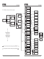
1
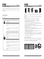
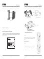
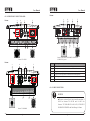
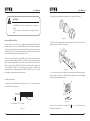
User Manual
Add : No. 17, Xiangshan Road, Guangzhou Science City, Guangdong, China
Zip: 510663
Tel: +86 20 6660 8532
Fax: +86 20 6660 8617
E-mail: [email protected]
Web: www.saj-solar.com
Sununo-TL Series
*Note:Since Guangzhou Sanjing Electric Co.,Ltd has a policy of continuous product improvement,
it reserves the right to change design and specifications without notices.
*Edition No.:V1.1_E(MC)
Preface
Thank you for choosing SAJ solar inverter. We are happy to provide
you with first-class products and quality service.
The manual includes installation, operation, maintenance,
troubleshooting, and safety notice. As long as you follow the
instruction of this manual, you will get the professional guidance
and our wholehearted service.
Customer-orientation is our forever commitment. We hope this
“User Manual” become your good helper in solar power generation.
This manual subjects to change at regular intervals according to
customer's feedback.
Please check the latest version at www.saj-solar.com
Guangzhou Sanjing Electric Co., Ltd.
GREEN TECHNIC
GREEN FUTURE
User Manual
User Manual
Contents
1. Notes on This Manual ...............................................................................1
6.2 Overview of Connection Area ...........................................................21
1.1 Scope of Validation ............................................................................1
6.3 AC Side Connection ..........................................................................22
1.2 Symbols Used .......................................................................................1
6.4 DC Side Connection ..........................................................................26
1.3 Target Group ........................................................................................2
6.5 DC Side Disconnection ......................................................................31
2. Preparation ................................................................................................2
6.6 Communication and Monitoring Setting ...........................................31
2.1 System Demonstration ........................................................................2
6.6.1 Communication through RS485 ........................................................31
2.2 Safety Instructions ................................................................................3
6.6.2 Communication through Ethernet ....................................................33
2.3 Explanations of Symbols on Inverter ................................................5
6.6.3 Cable Assembly Instructions ............................................................34
3. Product Information .................................................................................6
3.1 Overview ..............................................................................................6
3.2 Major Characteristics ..........................................................................7
3.3 Datasheet ............................................................................................8
4. Unpacking ................................................................................................12
4.1 Assembly Parts ..................................................................................12
4.2 Further Information ............................................................................13
5. Installation ...............................................................................................13
5.1 Safety ..................................................................................................13
5.2 Mounting Instructions .......................................................................14
5.3 Safety Clearance ...............................................................................14
7. LCD Operation ........................................................................................38
7.1 LCD Display ......................................................................................38
7.2 Operation Method ...............................................................................38
7.2.1 Button Function .............................................................................38
7.2.2 LCD Menu ......................................................................................39
7.2.3 Set The Country First ...................................................................41
7.2.4 State ................................................................................................41
7.2.5 Running-Info ..................................................................................41
7. 2. 6 Statistic-Info ...................................................................................42
7.2.7 Current Error ..................................................................................42
5.4 Mounting Procedure .........................................................................15
7.2.8 History Errors .................................................................................43
5.5 Check Varistors ...................................................................................17
7.2.9 Set-Param .......................................................................................43
5.6 Maintenance .......................................................................................19
7.2.10 Inverter-Info .................................................................................45
5.7 Module Technology ............................................................................19
8. Recycling and Disposal ...........................................................................45
5.8 Pollution Degree ................................................................................19
9. Troubleshooting ......................................................................................46
5.9 Overvoltage Category ........................................................................19
10. Guaranty Service ...................................................................................54
6. Electrical Connection .............................................................................20
11. Contact SAJ ...........................................................................................54
6.1 Safety ..................................................................................................20
Abbreviation .................................................................................................55
User Manual
User Manual
1.
NOTES ON THIS MANUAL
1.3 TARGET GROUP
1.1 SCOPE OF VALIDATION
This User Manual discribes instructions and detailed procedures for installing,
operating, maintaining, and troubleshooting of the following SAJ grid-tie
inverters:
Sununo– TL1.5K,
Sununo– TL2K,
Sununo– TL3KB,
Sununo– TL3KA,
Sununo– TL4KA,
Sununo– TL5K
SU3KMTLI,
SU4KMTLI,
Sununo– TL4KB,
SU5KMTLI
Please keep this manual all time available in case of emergency.
1.2 SYMBOLS USED
Only qualified electricians who have read and fully understood all safety
regulation contained in this manual can install, maintain and repair the
inverter. Operators must be aware of the high-voltage device.
2.
PREPARATION
2.1 SYSTEM DEMONSTRATION
Solar energy generation systems, based on photovoltaic modules, nowadays
represent the most suitable solution to reduce the energy consumption
produced by oil and gas.
The solar inverter is a key device in a solar energy system. It performs the
conversion of the variable DC output of the PV modules into a clean sinusoidal
50Hz/60Hz AC current that is then directly applied to the commercial
electrical grid or to a local grid electrical network.
DANGER
DANGER indicates a hazardous situation which, if not
avoided, will result in death or serious injury.
WARNING
Typically, solar inverter includes communication function to monitor
operating condition, firmware to update and control the grid connection.
Depending on the grid infrastructure, cabled (RS-485, CAN, Power Line
Communication, Ethernet) or cableless (Bluetooth, ZigBee/IEEE802.15.4)
networking options can be used.
WARNING indicates a hazardous situation which, if not
avoided, can result in death or serious injury or moderate
injury.
Solar
inverter
CAUTION
CAUTION indicates a hazardous condition which, if not
avoided, can result in minor or moderate injury.
Sell
Solar
Panels
Purchase
NOTICE
Grid
NOTICE indicates a situation that can result in potential
damage, if not avoided.
1
Figure 2.1
2
User Manual
User Manual
2.2 SAFETY INSTRUCTIONS
DANGER
CAUTION
·DANGER due to electrical shock and high voltage
·The PV inverter will become hot during operation.
·Do not touch the operating component of the inverter, it
might result in burning or death.
during or shortly after operation.
·To prevent risk of electric shock during installation and
maintenance, please make sure that all AC and DC
terminals are plugged out.
·D o not touch the surface of the inverter while the
housing is wet, it might lead to electrical shock.
·D o not stay close to the instruments while there are
severe weather conditions including storm, lighting, etc.
·Before opening the housing, the SAJ inverter must be
disconnected from the grid and PV generator; you must
wait at least five minutes to let the energy storage
capacitors fully discharged after disconnecting from
power source.
Please don’t touch the heat sink or peripheral surface
·Risk of damage due to improper modifications.
·Never modify or manipulate the inverter or other
components of the system.
·For radiation prevention, do not stay closer than 20cm
to the inverter for any length of time.
NOTICE
·Public utility only.
·The PV inverter is designed to feed AC power directly
to the public utility power grid; do not connect AC
output of the device to any private AC equipment.
WARNING
·The installation, service , recycling and disposal of
the inverters must be performed by qualified personnel
only in compliance with national and local standards and
regulations.
·Any unauthorized actions including modification of
product functionality of any form may cause lethal
hazard to the operator, third parties, the units or their
property. SAJ is not responsible for the loss and deny
these warranty claims.
·The SAJ inverter must only be operated with PV
generator. Do not connect any other source of energy to
the SAJ inverter.
·Be sure that the PV generator and inverter connect to
the ground in order to protect properties and persons.
3
4
User Manual
2.3 EXPLANATIONS OF SYMBOLS ON INVERTER
Symbol
Description
Dangerous electrical voltage
This device is directly connected to public grid, thus all
work to the inverter shall only be carried out by
qualified personnel.
User Manual
3.PRODUCT INFORMATION
3.1 OVERVIEW
Industrial design
Reduced Heat Sink
DANGER to life due to high electrical voltage!
There might be residual currents in inverter because of
large capacitors. Wait 5 MINUTES before you remove
the front lid.
NOTICE, danger!
This is directly connected with electricity generators
and public grid.
Danger of hot surface
The components inside the inverter will release a lot of
heat during operation. Do not touch metal plate housing
during operating.
Sununo-TL1.5K/2K
An error has occurred
Please go to Chapter 9 “Troubleshooting” to remedy the
error.
This device SHALL NOT be disposed of in residential
waste
Please go to Chapter 8 “Recycling and Disposal” for
proper treatments.
Sununo-TL3KB/4KB
Without Transformer
This inverter does not use transformer for the isolation
function.
Certified safety
The inverter complies with the requirement of the
Equipment and Product Safety Act in Europe.
Sununo-TL 3KA/4KA/5K
CE Mark
Equipment with the CE mark fulfills the basic
requirements of the Guideline Governing Low-Voltage
and Electro-magnetic Compatibility.
SAA Mark
The inverter complies with the requirement of Equipment
and Product Safety Act in Australia.
ATTENTION!
Risk of electric shock! Only
authorized personnel are
allowed to do disassembly,
modification or maintenance.
Any resulting defect or
damage (device/person) is not
covered by SAJ guaranty.
No unauthorized perforations or modifications
Any unauthorized perforations or modifications are
strictly forbidden, if any defect or damage
(device/person) is occurred, SAJ shall not take any
responsibility for it.
5
SU3KMTLI/SU4KMTLI/SU5KMTLI
Figure 3.1
6
User Manual
User Manual
3.3 DATASHEET
3.2 MAJOR CHARACTERISTICS
SAJ grid - tie solar inverter has following characteristics which make SAJ
grid - tie solar inverter “High Efficiency, High Reliability, High Cost Effective Ratio”.
• High input voltage, can be connected with more PV panels
• TWO MPP trackers, wide MPPT voltage range fits in different locations or
various weather conditions
• High MPP tracking accuracy, catch most of electricity from panels
• Transformerless design
• PC remote control, multi communication interface (Ethernet, RS485,wifi
etc.)
• Multi language display
• Easy LCD operation
• DC switch (optional)
• High-grade power component
• Small size, light weight, easy installation
Besides, following protection methods are integrated in SAJ grid - tie solar
inverter:
• Internal overvoltage protection
• DC insulation monitoring
• DC side varistor
• Ground fault protection
• Grid monitoring
• Ground fault current monitoring
• Anti-islanding protection
7
Type
Sununo-TL1.5K
Sununo-TL2K
Input (DC)
Max. DC Power [W]
1800
2300
Max. DC Voltage [V]
480
MPPT Voltage Range [V]
120-384
MPPT Voltage Range[V](Full Load)
164-384
190-384
DC Nominal Voltage [V]
360
Start Voltage [V]
150
Min. DC Voltage [V]
100
Max. DC Current (/ Per String)[A]
11
12
Number of DC Connection Sets
1
Number of MPP Trackers
1
DC Switch
Optional
Output (AC)
Rated AC Power [W]
1500
2000
Max. AC Power [W]
1650
2000
Rated AC Current [A]
6.5
8.7
Max. AC Current [A]
8.5
11.0
Norminal AC Voltage/Range
220V, 230V, 240V/180V-280V
Grid Frequency/Range
50Hz, 60Hz/ ±5Hz
Power Factor(cos φ)
1 [full load]
AC Current Distortion (THD)
< 2%
Consumption at Night [W]
<0.2
Consumption at Standby [W]
6
Efficiency
Max. Efficiency
97.4%
97.4%
Euro Efficiency (at 360Vdc)
96.5%
96.7%
MPPT Accuracy
>99.5%
Protection
Internal Overvoltage Protection
Integrated
DC Insulation Monitoring
Integrated
DC Side Varistors
Integrated
Direct Current Monitoring
Integrated
Ground Fault Current Monitoring
Integrated
Grid Monitoring
Integrated
AC Short Current Protection
Integrated
Thermal Protection
Integrated
Anti-island protection monitoring
AFD
Interface
AC Connection
Terminals
DC Connection
MC4/H4
LCD Display
LCD(16x2 Characters, Backlight) & LED(3 Lights)
Display Language
Multi Language
Datalogger & Communication
2*RS485(Standard), WiFi/Ethernet(Optional)
General Data
Isolation
Transformerless
Operating Temperature Range
-25°C to +60°C [45°C to 60°C with derating ]
Cooling Method
Natural Convection
Ambient Humidity
0% to 98% Non-condensing
Site Altitude above Sea Level
Up to 2000m
Noise Emission [dB(A)]
<40
IP Protection
IP65 [Indoor or Outdoor Installation]
Mounting
Rear Panel
Dimensions (WxHxD) [mm]
415*313*140
Weight [kg]
11
Standard Warranty (Year)
5 / 10/15/20/25 [Optional]
Safety Class Compliance
AS3100,, IEC62109-1/-2
EMC Compliance
EN61000-6-1:4, EN61000-3-2:3
Grid Protection Compliance
VDE 0126-1-1,UTE C15-712-1, G83, C10/11, AS4777,EN50438
8
User Manual
User Manual
Type
Sununo-TL3KB
Sununo-TL4KB
Input (DC)
Max. DC Power [W]
3400
4500
Max. DC Voltage [V]
550
MPPT Voltage Range [V]
125-440
MPPT Voltage Range[V](Full Load)
200-440
225-440
DC Nominal Voltage [V]
360
Start Voltage [V]
150
Min. DC Voltage [V]
100
Max. DC Current (/ Per String)[A]
17
20
Number of DC Connection Sets
2
Number of MPP Trackers
1
DC Switch
Optional
Output (AC)
Rated AC Power [W]
3000
4000
Max. AC Power [W]
3300
4400
Rated AC Current [A]
13.0
17.4
Max. AC Current [A]
15.0
20.0
Norminal AC Voltage/Range
220V, 230V, 240V/180V-280V
Grid Frequency/Range
50Hz, 60Hz/ ±5Hz
Power Factor(cos φ)
1 [full load]
AC Current Distortion (THD)
< 2%
Consumption at Night [W]
<0.2
Consumption at Standby [W]
6
Efficiency
Max. Efficiency
97.7%
97.7%
Euro Efficiency (at 360Vdc)
97.1%
97.1%
MPPT Accuracy
>99.5%
Protection
Internal Overvoltage Protection
Integrated
DC Insulation Monitoring
Integrated
DC Side Varistors
Integrated
Direct Current Monitoring
Integrated
Ground Fault Current Monitoring
Integrated
Grid Monitoring
Integrated
AC Short Current Protection
Integrated
Thermal Protection
Integrated
Anti-island protection monitoring
AFD
Interface
AC Connection
Terminals
DC Connection
MC4/H4
LCD Display
LCD(16x2 Characters, Backlight) & LED(3 Lights)
Display Language
Multi Language
Datalogger & Communication
2*RS485(Standard), WiFi/Ethernet(Optional)
General Data
Isolation
Transformerless
Operating Temperature Range
-25°C to +60°C [45°C to 60°C with derating ]
Cooling Method
Natural Convection
Ambient Humidity
0% to 98% Non-condensing
Site Altitude above Sea Level
Up to 2000m
Noise Emission [dB(A)]
<40
IP Protection
IP65 [Indoor or Outdoor Installation]
Mounting
Rear Panel
Dimensions (WxHxD) [mm]
450*375*177
Weight [kg]
21
Standard Warranty (Year)
5 / 10/15/20/25 [Optional]
Safety Class Compliance
AS3100,, IEC62109-1/-2
EMC Compliance
EN61000-6-1:4, EN61000-3-2:3, EN61000-3-11:12
Grid Protection Compliance
VDE 0126-1-1,UTE C15-712-1, G83/G59, C10/11, AS4777,EN50438
Type
Sununo-TL3KA
Sununo-TL4KA
Input (DC)
Max. DC Power [W]
3200
4200
Max. DC Voltage [V]
550
MPPT Voltage Range [V]
125-440
MPPT Voltage Range[V](Full Load)
200-440
DC Nominal Voltage [V]
360
Start Voltage [V]
150
Min. DC Voltage [V]
100
Max. DC Current (/ Per String)[A]
16A/15A
21A/15A
Number of DC Connection Sets
2
Number of MPP Trackers
2
DC Switch
Optional
Output (AC)
Rated AC Power [W]
3000
4000
Max. AC Power [W]
3000
4000
Rated AC Current [A]
13.0
17.4
Max. AC Current [A]
15.0
20.0
Norminal AC Voltage/Range
220V, 230V, 240V/180V-280V
Grid Frequency/Range
50Hz, 60Hz/ ±5Hz
Power Factor(cos φ)
1 [full load]
AC Current Distortion (THD)
< 2%
Consumption at Night [W]
<0.2
Consumption at Standby [W]
6
Efficiency
Max. Efficiency
97.6%
97.6%
Euro Efficiency (at 360Vdc)
96.8%
96.8%
MPPT Accuracy
>99.5%
Protection
Internal Overvoltage Protection
Integrated
DC Insulation Monitoring
Integrated
DC Side Varistors
Integrated
Direct Current Monitoring
Integrated
Ground Fault Current Monitoring
Integrated
Grid Monitoring
Integrated
AC Short Current Protection
Integrated
Thermal Protection
Integrated
Anti-island protection monitoring
AFD
Interface
AC Connection
Terminals
DC Connection
MC4/H4
LCD Display
LCD(16x2 Characters, Backlight) & LED(3 Lights)
Display Language
Multi Language
Datalogger & Communication
2*RS485(Standard), WiFi/Ethernet(Optional)
General Data
Isolation
Transformerless
Operating Temperature Range
-25°C to +60°C [45°C to 60°C with derating ]
Cooling Method
Natural Convection
Ambient Humidity
0% to 98% Non-condensing
Site Altitude above Sea Level
Up to 2000m
Noise Emission [dB(A)]
<40
IP Protection
IP65 [Indoor or Outdoor Installation]
Mounting
Rear Panel
Dimensions (WxHxD) [mm]
525*425*175
Weight [kg]
23
Standard Warranty (Year)
5 / 10/15/20/25 [Optional]
Safety Class Compliance
AS3100,, IEC62109-1/-2
EMC Compliance
EN61000-6-1:4, EN61000-3-2:3, EN61000-3-11:12
Grid Protection Compliance
VDE 0126-1-1,UTE C15-712-1, G83/G59, C10/11, AS4777,EN50438
9
10
User Manual
User Manual
Type
Sununo-TL5K
Input (DC)
Max. DC Power [W]
5200
Max. DC Voltage [V]
550
MPPT Voltage Range [V]
125-440
MPPT Voltage Range[V](Full Load)
200-440
DC Nominal Voltage [V]
360
Start Voltage [V]
150
Min. DC Voltage [V]
100
Max. DC Current (/ Per String)[A]
26A / 16A
Number of DC Connection Sets
2
Number of MPP Trackers
2 [can parallel]
DC Switch
Optional
Output (AC)
Rated AC Power [W]
5000
Max. AC Power [W]
5000
Rated AC Current [A]
21.7
Max. AC Current [A]
25
Norminal AC Voltage/Range
220V, 230V, 240V/180V-280V
Grid Frequency/Range
50Hz, 60Hz/±5Hz
Power Factor(cos φ)
1 [full load]
AC Current Distortion (THD)
< 2%
Consumption at Night [W]
<0.2
Consumption at Standby [W]
6
Efficiency
Max. Efficiency
97.7%
Euro Efficiency (at 360Vdc)
97.1%
MPPT Accuracy
>99.5%
Protection
Internal Overvoltage Protection
Integrated
DC Insulation Monitoring
Integrated
DC Side Varistors
Integrated
Direct Current Monitoring
Integrated
Ground Fault Current Monitoring
Integrated
Grid Monitoring
Integrated
AC Short Current Protection
Integrated
Thermal Protection
Integrated
Anti-island protection monitoring
AFD
Interface
AC Connection
Terminals
DC Connection
MC4/H4
LCD Display
LCD(16x2 Characters, Backlight) & LED(3 Lights)
Display Language
Multi Language
Datalogger & Communication
2*RS485(Standard), WiFi/Ethernet(Optional)
General Data
Isolation
Transformerless
Operating Temperature Range
-25°C to +60°C [45°C to 60°C with derating ]
Cooling Method
Natural Convection
Ambient Humidity
0% to 98% Non-condensing
Site Altitude above Sea Level
Up to 2000m
Noise Emission [dB(A)]
<40
IP Protection
IP65 [Indoor or Outdoor Installation]
Mounting
Rear Panel
Dimensions (WxHxD) [mm]
525*425*190
Weight [kg]
26
Standard Warranty (Year)
5 / 10 /15/20/25 [Optional]
Safety Class Compliance
AS3100, IEC62109-1/-2
EMC Compliance
EN61000-6-1:4, EN61000-3-2:3, EN61000-3-11:12
Grid Protection Compliance
VDE 0126-1-1, UTE C15-712-1, G59, C10/11,AS4777,EN50438
* Here indicastes there is another unit [VA] of these data which is applied to C10/11.
11
** Sununo-TL5K/4KA/3KA has different dimensions for enclosure as
SU5KMTL1、SU4KMTL1、SU3KMTL1,detail see table documents.
4. UNPACKING
4.1 ASSEMBLY PARTS
After you receive the SAJ grid-tie solar inverter, please check if there is any
damage on the carton. Also, please check the inside completeness and for any
visible external damage on the inverter or any accessories. Contact your dealer
if anything is damaged or missing.
C
B
A
E
D
H
G
F
I
Figure 4.1
Object
Quantity
A
1
B
1
Description
SAJ grid-tie solar inverter
Rear panel
1 sets
DC connector (for Sununo-TL1.5K/2K)
2 sets
DC connector (for Sununo-TL3KB/4KB/3KA/4KA/5K,
SU3KMTLI, SU4KMTLI, SU5KMTLI)
C
D
2
RS485 connector(if attached)
E
6
M6×50 Expansion screw
F
6
Expansion tube
M4×12 Cylinder head screw and Lock washer
G
4
(Sununo-TL1.5K/2K/3KB/4KB)
M5×12 Cylinder head screw and Lock washer
(Sununo-TL3KA/4KA/5K, SU3KMTLI, SU4KMTLI,SU5KMTLI)
H
1
User manual, including installation guide
I
1
Warranty card
12
User Manual
User Manual
5.2 MOUNTING INSTRUCTIONS
4.2 FURTHER INFORMATION
15
If you have any further questions concerning the type of accessories or
installation, please check our website www.saj-solar.com or contact our
service hotline.
Bad cooling
Figure 5.1
·SAJ grid - tie solar inverter is cooled by natural flow of air behind the
inverter.
·SAJ grid - tie solar inverter is designed for installation both indoors and
outdoors.
·Please only mount the inverter in the direction as illustrated above.
5. INSTALLATION
5.1 SAFETY
DANGER
·DANGER to life due to potential fire or electricity
shock.
·D o not install the inverter near any inflammable or
explosive items.
·This inverter will be directly connected with HIGH
VOLTAGE power generation device; the installation
must be performed by qualified personnel only in
compliance with national and local standards and
regulations.
NOTICE
·NOTICE due to the inappropriate or the harmonized
·Installation of the inverter in the vertical direction is recommended.
·Tilted backward max.15 degree is allowed.
·Never install the device Forward horizontally or even upside down.
·For the convenience of checking the LCD display and possible maintenance
activities, please install the inverter at eye level.
·Make sure the wall you selected is strong enough to handle the screws and
the weight of the inverter.
·Ensure the device is properly fixed to the rear panel.
·Installing the inverter under strong sunshine is not recommended; the excess
heating might lead to power reduction.
·The ambient temperature of installation site should be between - 25 °C and
+60 °C ( between -13 °F and 140 °F ) .
·Make sure enough ventilation at installation spot; insufficient ventilation
may affect the operating performance of the inside electronic components,
even shorten the life span of the device.
5.3 SAFETY CLEARANCE
To make sure the ventilation of the installation spot, if there are multiple SAJ
grid-tie solar inverters installed in the same area, the following safety
clearance shall be followed for proper ventilation conditions.
30cm
installation environment may jeopardize the life span of
the inverter.
·The installation site must have good ventilation
condition.
13
Direction
Above
Below
Side
Front
Minimum Clearance
30 cm
50 cm
30 cm
5 cm
5cm
30cm
Figure5.2
14
30cm
50cm
·Installation directly exposed under intensive sunshine
is not recommended.
User Manual
5.4 MOUNTING PROCEDURE
1. Use the rear panel in the package as a drilling template and mark the
positions of the drill holes, as illustrated below.
User Manual
2. According to the marks, drill 6 holes in the wall (in conformity with position
marked in above picture), and then place expansion tubes in the holes using a
rubber hammer.
268
230
346
280
2-φ8
Figure 5.4
Sununo-TL1.5K/2K
8
280
346
280
2-φ
8
304
230
294
16
3. Mount the rear panel.
Wring six screws into the expansion tubes and tightly mount the rear
panel on the wall.
Figure 5.5
Sununo-TL3KA/4KA
SU3KMTLI/SU4KMTLI
Sununo-TL3KB/4KB
290
9
2-φ
9
4. Carefully attach the inverter to the rear panel according to the position of the
screws.Make sure the backside of the inverter is closely against the rear panel.
When two people transport the inverter, make sure each one use the hand grip in
right position as illustrated in the picture.
294
19
Notch
Figure 5.6
Sununo-TL/5K
SU5KMTLI
5. Pay attention to the four notches cut in both flanks of heat sink (as illustrated
in above picture), which should be placed in corresponding hooks from the rear
panel. Make sure that the heat sink and the rear panel are buckled together and
the inverter is tightly attached to the rear panel. And tighten the screws with
5.9N·m torque.
Figure 5.3
15
16
User Manual
User Manual
6. Please carefully check the accessories and original carton to make sure
during the installation every necessary part is used and nothing is missing.
2. There are 2 varistors for Sununo-TL1.5K/2K/3KB/4KB and 4 varistors for
Sununo-TL 3KA/4KA/5K/SU3KMTLI/SU4KMTLI/SU5KMTLI in the left side.
Sununo-TL1.5K/2K
Sununo-TL3KB/4KB
Figure 5.7
Figure 5.9
5.5 CHECK VARISTORS
Sununo-TL 3KA/4KA/5K
SU3KMTLI/SU4KMTLI/SU5KMTLI
If one or more of the varistors might be out of function, please check or replace
the varistors according to the following steps:
1. Loosen all 4 captive screws of the removable front lid. Right after the
4 captive screws are removed, please keep them at a distance. Lift the lid
upwards and remove it.
3. Remove and install the varistors
Remove:
First use specified tool and insert it to three holes
in the left side of the varistor, then press it to the
end.
Pull the varistor out.
Figure 5.10
Install:
Use specified tool and insert it to three holes in
the left side of the varistor, then press it to the
end.
Figure 5.8
Press the varistor in.
Figure 5.11
17
18
User Manual
4. Put the lid back and re-screw all 4 screws, make sure the lid is tightening to
the inverter.
User Manual
6. ELECTRICAL CONNECTION
6.1 SAFETY
5.6 MAINTENANCE
Ask your installer to check for proper inverter operation at regular
intervals.
5.7 MODULE TECHNOLOGY
DANGER
·DANGER to life due to potential fire or electricity
SAJ grid - tie solar inverters provide the optimal solution for any module.
Transformerless-type SAJ grid-tie solar inverters are designed for ungrounded
modules, especially for the crystalline silicon photovoltaic modules, such as
monocrystalline silicon and polycrystalline silicon. While the thin-film
modules are not suitable for SAJ transformerless inverters.
5.8 POLLUTION DEGREE
SAJ grid-tie solar inverters comply with the pollution degree 3.
5.9 OVERVOLTAGE CATEGORY
shock.
·With the inverter powered, comply with all prevailing
national regulations on accidents prevention.
·This inverter will be directly connected with HIGH
VOLTAGE power generation device; the installation
must be performed by qualified personnel only in
compliance with national and local standards and
regulations.
NOTICE
Overvoltage category III applies to SAJ grid - tie solar inverter AC
terminals. For PV circuits in general, Overvoltage Category II is assumed.
·Electrical connections shall be carried out in
accordance with the applicable regulations, such as
conductor sections, fuses, earthing protection.
19
20
User Manual
Bottom:
6.2 OVERVIEW OF CONNECTION AREA
Bottom:
C
B
A
User Manual
A
E
C
B
F
F
E
D
D
Sununo-TL3KA/4KA/5K/SU3KMTLI/SU4KMTLI
SU5KMTLI /Figure 6.1
Sununo-TL1.5K/2K
Bottom:
A
C
B
E
Object
Description
A
DC switch to turn off the inverter manually(optional)
B
DC input
C
Plug for connecting the RS485 communication module
D
Plug for connecting Ethernet communication module (optional)
E
AC output
F
Heat sink
6.3 AC SIDE CONNECTION
NOTICE
F
D
·The cross-section of the AC cable should be more than 12
AW G f o r S u n u n o - T L 1 . 5 K / 2 K a n d 1 0 AW G f o r
Sununo-TL3KB/4KB/3KA/4KA/5K,SU3KMTLI
SU4KMTLI/SU5KMTLI and Cable Rangeφ9-14mm.
Sununo-TL 3KB/4KB
21
22
User Manual
User Manual
To do this , the insulated earthing conductor must be 5mm longer than the
insulated L and N conductors! L and N must not be swapped.The ground wire
shall be larger than phase conductor.
Sununo-TL3KA/4KA/5K
Figure 6.6
5. Aim the terminals on the straight plug to the holes of the grommet, and then
compress them together.
Sununo-TL1.5K/2K
Figure 6.7
6. Finally, connect the straight plug to the AC terminal on inverter. Pay
attention to the polarity of the terminals to avoid wrong connecting.
6.4 DC SIDE CONNECTION
Sununo-TL 3KB/4KB
NOTE:
The cable length on DC side should not exceed 30 m.
25
26
User Manual
User Manual
2. Screw off and separate each component of AC connector as follows.
DANGER
·DANGER to life due to potential fire or electricity
shock.
·Never connect or disconnect the connectors under
load.
Figure 6.3
Integrated RCD and RCM
The SAJ grid - tie solar inverter is equipped with integrated RCD (Residual
Current Protective Device) and RCM (Residual Current Operated Monitor).
The current sensor will detect the volume of the leakage current and compare it
with the pre-set value. If the leakage current is above the permitted range, the
RCD will disconnect the inverter from the AC load.
The SAJ grid-tie solar inverter will probably cause a DC current in the external
protective earthing conductor. Where a residual current-operated protective
(RCD) or monitoring (RCM) device is used for protection in a case of direct or
indirect contact, only an RCD or RCM of Type B is allowed on the supply side
of this product. Provided an AC current or pulse current is caused in the
external protective earthing conductor, an RCD or RCM of Type AC or Type A
as alternative can be permitted putting into use.
3. Pass the cable through each component from right to the left as follows.
Tighten the screws with 3.0N·m torque.
Figure 6.4
4. Use a screw driver and loose the three screws at the side of the straight plug.
Then insert the stripped N, L and PE cable accordingly to the corresponding
position and fully tighten the screws.
Assembly Instructions:
1. Strip the cable with the length 0.276 inches (9/32″) - (7mm) and please be
careful NOT to nick conductors.
Cable
Figure 6.5
0.276 inches(9/32″)-(7mm)
Figure 6.2
23
Connect L, N and protective conductor (
accordance with the label.
24
) to the AC terminal in
User Manual
For Sununo – TL 1.5K/2K/3KB/4KB, there is just one MPP Tracker. These
single MPPT inverters require same type module with same quantity, identical
alignment and tilt.
User Manual
NOTICE
·Before electrical connection setup, installer shall
For Sununo–TL3KA/4KA/5K,SU3KMTLI/SU4KMTLI/SU5KMTLI, there are
two MPP Trackers for the two string inputs. Unlike the traditional single MPPT
inverters which require same type module, same quantity, identical alignment
and tilt, the multi-MPPT SAJ grid-tie inverters can deal with different solar
modules, different quantity, different alignment and tilt, thus can withstand
harshest environmental conditions.
make sure the inverter is isolated and disconnected from
the PV source and AC grid.
·The inverter may only be operated with PV generators
(Class A PV modules according to IEC 61730 and
cabling) of protection class II. Do not connect any
sources of energy other than PV modules to the inverter.
Inverter Type
Sununo-TL1.5K
Sununo-TL2K
Sununo-TL3KB
Sununo-TL4KB
Sununo-TL3KA,
SU3KMTLI
Sununo-TL4KA,
SU4KMTLI
Sununo-TL5K,
SU5KMTLI
MPP Tracker
1
Max. DC
Power (W)
1800
2300
3400
4500
Max.DC
Max.DC Voltage Current/per string(A)
11
480V
12
17
20
NOTICE
No mixed connections between input zones(for Sununo-
3200
16A/15A
TL 3KB/4KB and Sununo-TL3KA/4KA/5K,
4200
21A/15A
SU3KMTLI/SU4KMTLI/SU5KMTLI).
·For instance, if the positive pole of a string is
26A/16A
connected at input zone 1 and the negative pole at input
550V
2
5200
zone 2, this is called a mixed connection.
·Only connect strings at one input zone and never mix
the input zones 1 and 2!
DANGER
·DANGER to life due to potential fire or electricity shock.
·Never connect or disconnect the connectors under load.
The DC connectors come pre-assembled and the caps are loose. The whole
connector will include the male side and female side as showed below:
NOTICE
·If only one string input is used for DC connection,
please use the sealing plug to seal the left DC input set to
ensure the inverter IP 65 protection.
Male side connector (M)
Female side connector (F)
Figure 6.8
27
28
User Manual
Assembly Instructions:
User Manual
Cable requirements:
1. Strip the cable with the length 0.276 inches (9/32")-(7mm) and please be
careful NOT to nick conductors.
Cable Size
2.5 mm 2
Min. 310 N (70 Lbs)
4 mm2
Min. 400 N (90 Lbs)
Min. 450 N (100 Lbs)
6 mm2
10 mm
Cable
0.276 inches(9/32")-(7mm)
Figure 6.9
Cable pull – out force requirement
2
Min. 500 N (110 Lbs)
4. Insert contact cable assembly into back of male and female connector. A
“click” should be heard or felt when the contact cable assembly is seated
correctly. See below figures.
Use specified strip tool in this step. Adjust the strip stopper and put the cable in
corresponding notch to strip the length of 7mm. See below figures.
Male side connector (M)
Figure 6.15
Figure 6.10
Figure 6.11
2. Insert stripped cable into contact barrel and insure all conductor strands are
captured in the contact barrel and the conductors are visible in the contact
barrel observation hole. See below figures.
Female side connector (F)
Figure 6.16
5. Wrest the cap by using the torque of 2.6~2.9N·m.
Socket contact
Pin contact
Barrel observation hole
Conductor should be visible
Barrel observation hole
Conductor should be visible
Figure 6.12
Figure 6.13
Figure 6.17
6. After wrested the cap tightly, align the 2 half connectors and mate them
together by hand until a “click” is heard or felt.
3. Crimp contact barrel by using the hex crimping die. ensure it is fixed.See
below figures.
Crimped pin contact
Crimped socket contact
Figure 6.14
Figure 6.18
29
30
User Manual
6.5 DC SIDE DISCONNECTION
Only qualified electricians who have fully understood all safety regulation
contained in this manual can disconnect and maintain the DC connectros.
User Manual
RS485 Multipoint Monitoring
To realize multipoint monitoring of SAJ solar inverter, we offer
2configurations as shown in below:
(1) PC Multipoint Monitoring
6.6 COMMUNICATION AND MONITORING SETTING
SAJ solar inverter offers 2 communication solutions for users: RS485
(standard) and Ethernet (optional). All the SAJ products involved in the solar
monitoring system are:
Sununo-TL series solar inverters: single phase transformerless on-grid solar
inverters, such as Sununo-TL1.5K/2K/3KA/4KA/5K,SU3KMTL1/
SU4KMTL1/SU5KMTL1
SAJ Logger: data logger for remote monitoring and maintenance of large
solar power plants.
SAJ Viewer: The free PC software solution for SAJ solar power plant
monitoring via RS485 or RJ45.
Note : The text lines in the following Figures indicates communication cable
Figure 6.20 PC Multipoint Monitoring
(2) SAJ Logger Multipoint Monitoring
6.6.1Communication through RS485
RS485 can be used for both singlepoint and multipoint communication. At
present, RS485 can communicate and monitor up to 32 points.
RS485 Singlepoint Monitoring
Communication of a single inverter is shown in Figure1 as below. Users can
connect inverter's RS485 port to PC through RS485/232 Module.
Figure 6.19 Communication of a Single Inverter
Figure 6.21 PC + SAJ Logger Multipoint Monitoring
31
32
User Manual
User Manual
Connection Procedures
1、Inverter 1 connects to Inverter 2 through RS485 cable; Inverter 2 connects
to Inverter 3 through RS485 cable. In the same way to connect all inverters.
2、Inverter 1 connects to RS485/232 Module through RS485-M cable or
connects to SAJ Logger through RS485-C cable.
3、Connect RS485/232 Module to PC's RS232 port, or connect SAJ Logger
to PC through Router.
4、Use SAJ Viewer or Internet browser ( if SAJ Logger is in use) in PC to
monitor Inverters.
6.6.3 Cable Assembly Instructions
Cable:All cables mentioned in this Manual are 5E Shielded Cable, as shown in
Figure6.23:
6.6.2 Communication through Ethernet
When users chose Ethernet communication solution, users can access to
Inverter's real-time information through Inverter's IP address, or through SAJ
Logger IP address. The configuration is shown in Figure6.22 as below:
Shield layers
Four STP
(n<=32)
Figure 6.23 5E Shielded Cable
Terminals:According to different communication solutions, users may need
at least one of the below Terminals. They are 3Pin Connector and RJ45 Plug as
shown in Figure6.24 and Figure6.25.
Figure 6.22 Communication through Ethernet
33
Figure 6.24 3Pin Connector
34
User Manual
User Manual
RS485-M cable
RS485-M cable is used to connect Inverter and RS485/232 Module. Users only
use 2 wires of the 5E cable to connect to the Connector and the RS485/232
Module according to Table 2. Make sure they are fixed well.
Connector No.
Wire
Figure 6.25 RJ45 Plug and Its Pin Number
Tools
When making a communication cable , at least one of the professional tool is
needed as shown in Figure6.26.
Blue & White
Blue
RS485 /232 Module
1
D-/B
2
D+/A
Table 2 RS485-M Cable Assembly Order
RS485-L cable
Figure 6.26 Tools for making a communicate cable
RS485 cable
When Inverters use RS485 for monitoring, users need RS485 cables to connect
between Inverters for multipoint monitor. In this case, we provide Connection
by using the 3Pin Connector as shown in Figure6.24.
Each end of the cable should be connected to the Connector according to Table
1. Make sure they are fixed well.
Connector No .
Wire
1
Blue & White
2
Blue
3
Metal shielded wire
RS485-L cable is used to connect Inverter and SAJ Logger when inverters are
monitored via RS485. One end of the cable uses 3Pin Connector, and the other
end uses RJ45 Plug. Connection is shown in Table 3 as below:
Connector No.
Wire
Blue & White
Blue
1
5
2
4
Table 3 RS485-L Cable Assembly Order
Table 1 RS485 Cable Assembly Order
35
RJ45 plug's Pin NO
36
User Manual
RJ45 cable
RJ45 cable is the standard cable for Ethernet communication. Users can buy
this cable in stores, or can assemble RJ45 cable as below:
Each end of the cable must be connected to RJ45 Plug according to Table 4.
Make sure they are fixed well.
RJ45 plug's Pin NO
One RJ45 plug's
Wire color
One RJ45 plug's
Wire color
1
White & Green
White & Orange
User Manual
7.
LCD Operation
7.1 LCD DISPLAY
ABC D
EF
Figure 7.1
2
3
4
5
Green
White & Green
Orange
White & Orange
Blue
Blue
White & Blue
White & Blue
Object
Description
A
LED light – POWER. Yellow light shines when the inverter is energized.
B
LED light-FAULT. Red light shines when fault occurs in the inverter and
automatically goes out when the fault is removed.
C
LED light-RUN. Green light flashes when the inverter runs good.
D
▼/ESC
E
▲/ENT
F
LCD screen for viewing the running data & recorded information,
and setting parameters.
7.2 Operation Method
7.2.1 BUTTON FUNCTION
6
Orange
Green
SAJ grid-tie solar inverter offers two buttons for user to look up running
information and configure parameters. The two buttons can be reused.
Name
7
White & Brown
White & Brown
Operation
Description
Press less than
one second
It indicates the“▼ ”button, which can move the cursor
downwards in the menu, or decrease the setting value.
Press more than
one second
It indicates the “ ESC ” button, which can return to
parent menu or cancel the demand.
Press less than
one second
It indicates the “▲” button, which can move the cursor
upward in the menu, or increase the setting value.
Press more than
one second
It indicates the “ ENT ” button, which can enter
submenu or confirm the command.
▼/ ESC
8
Brown
Brown
▲/ ENT
Table 4 RJ45 Cable Assembly Order
NOTE: The back light of LCD screen will go out to save power if there is no
button operation in one minute. You can activate it by pressing any button.
37
38
User Manual
User Manual
2011/11/09 18:17
State Normal
P-ac 1221W
V-grid 220.0V
7.2.2 LCD Menu (Take Sununo-TL3KA as an example)
Enter
V-PV1 350.2V
I-PV1 2.37A
Enter
E-Month 692.3KWh
04/01
15.4 KWh
……
Enter
E-Year
Jan.
……
Enter
E-Total 19812.5 KWh
2012
9125.3KWh
……
Enter
If the country
hasn't been set
UP
> Running-Info
Statistic-Info
DOWN
E-today 0.5kWh
P-ac
1221W
V-PV2 349.7V
I-PV2 2.63A
Temp.
On-Grid Inverter
Sununo-TL3KA
Please Set The
Country First
> Current Error
History Errors
Enter
2011/11/09 18:17
State Normal
DOWN
> E-Today
E-Month
Enter
> E-Year
E-Total
Enter
DOWN
> Set-Param
Inverter-Info
0.5kWh
T-Today
0.5h
Enter
T-Total
Enter
Error Code:03
Grid Freq Err
..............
Enter
Enter
..............
Enter
Please Enter
Password:xxxxxx
5418.1h
> E-Today
E-Total
Enter
Error Code:02
Grid Volt Err S
..............
Enter
>12/08/26 17:52
12/08/07 10:05
..............
8523.7KWh
552.1KWh
S
> Language
Date
> Time
Grid Compliance
Enter
UP
DOWN
You can access into the next level menu by pressing ENTER KEY
Enter
>Ethernet
Wifi
Please Enter
Password:xxxxxx
Enter
> Change Password
Clear Errors
Machine Type
Sununo-TL3KA
Enter
Grid Compliance
Belgium
> Clear Energy
Factory Setting
Enter
SN:13020G1101DE0
0500
Enter
PC:SU3KMTL1DE6
E0000
> Machine Type
Grid Compliance
You can go back to the former level menu by pressing ESC KEY
UP
Enter
DOWN
> SN Code
Product Code
39
UP
Enter
> Firmware Ver
> Australia
Austria
Enter
DOWN
By pressing the key
UP or Down, you
can get access to
different item of the
same level menu
31.2℃
UP
UP
E-Today
I-grid 5.50A
F-grid 49.99Hz
DOWN
40
MCUF: V01.00
SCUF : V01.01
DBF:
EV1.00
Enter
UP
..............
Please Enter New
Password:xxxxxx
User Manual
7.2.3 Set The Country First
When the solar inverter begins to run for the first time, please configure the
country of usage, and the inverter LCD will display as below:
Please Set The
Country First
Please press the "ENT" button, LCD will show the countries for option. Users
can press "▼ " or"▲ " to move the cursor">"to select the correct country and
press "ENT" button to confirm the selection.
Note: The configuration of the country of usage must be set before inverter
starts to run for its first time, otherwise the inverter will not on-gird.
If users choose an incorrect country, it could lead to the inverter not running
properly or reporting error frequently. Please make sure you select the correct
country. User can enter the menu of "Inverter-Info->Grid Compliance" to
check whether the setting is correct.
If users can not fond out the corrsponding country,please stop the setting and
contact the after sales for confirmatior.
7.2.4 State
If the country has been set , the LCD shows the machine type when the inverter
is started up, then it automatically displays the inverter operation status:
Normal,Wait, Shutdown, Fault, P-Fault, Update.
Data name
Normal
Wait
Shutdown
Fault
P-fault
Update
Explanation
The inverter in normal (function) operation
The inverter in stand-by state
The inverter stops working
A fault occurs during operation
A fault occurs repeatedly and has reached a certain times during
operation
The state of updating firmware
Press “ENT” to enter the second level menus.
> Running-Info
S tatistic-Info
> Current Error
History Errors
> Set-Param
Inverter-Info
7.2.5 Running-Info
1.The “Running-Info” includes real time system data. All the data are explained in
the following Table.
Electrical Real Time Data ( Running-Info )
Data name
P-ac
V-grid
I-grid
F-grid
V-PV1
I-PV1
V-PV2*
I-PV2*
Temp.
Explanation
Output AC power
Grid voltage
Output AC current
Grid frequency
DC Voltage of PV array1
DC Current of PV array1
DC Voltage of PV array2
DC Current of PV array2
The temperature of the inverter
Unit
W
V
A
Hz
V
A
V
A
℃
User Manual
7.2.6 Statistic-Info
“Statistic-Info” includes some statistics information. All the data are explained
in the following table.
Data name
E-Today
E-Month
E-Year
E-Total
T-Today
T-Total
Explanation
The generated energy of current day
Total generated energy of the month and the
daily generated energy of current month
Total generated energy of current year and the
monthly generated energy of current year.
The total energy generated by the inverter and
total generated energy of the year.
The operating time of current day
Total hours of operation time
kWh
kWh
kWh
h
h
7.2.7 Current Error
If any of the following messages occurs in LCD Screen, and the status LED
Light “ Fault” is on, there is one or more error that has been detected by SAJ
grid-tie solar Inverter.
Please go to Chapter 9 “TROUBLESHOOTING” for further information
Error
Consistent Err
Grid Volt Err
Grid Freq Err
Grid Loss Err
Bus Over Volt
GFCI Err
Over-TEMP.
PV Over Volt
AC Over Current
Isolation Err
Grid Volt Err
Grid Freq Err
V-Grid 10m Err
DCI Err
GFCI Err
Over-TEMP.
Other Err
Int. Comm Err
CurrSensor Err
S
S
S
S
S
S
S
S
M
M
M
M
M
M
M
M
S
S
S
Explanation
Consistent Error (Slave**)
Grid Voltage Error (Slave)
Grid Frequency Error (Slave)
Grid Loss Error (Slave)
Bus Over voltage(Slave)
GFCI Error (Slave)
Over-temperature (Slave)
PV-Overvoltage (Slave)
AC-Overcurrent (Master*)
Isolation Error (Master)
Grid Voltage Error (Master)
Grid Frequency Error (Master)
Grid Voltage 10min Error (Master)
DCI Error (Master)
GFCI Error (Master)
Over-temperature (Master)
Other Error (Slave)
Internal Communication Error (Slave)
Current Sensor Error (Slave)
*: The single MPPT inverters Sununo-TL1.5K/2K/3KB/4KB do not have these two items.
41
Unit
kWh
42
Type of Error
Error
Permanent
Error
User Manual
Error
Varistor Err
2.5V Ref Err
Other Err
CurrSensor Err
GFCI Dvc Err
Int. Comm Err
E2PROM R/W Err
2.5V Ref Err
DCI Device Err
Relay Err
S
S
M
M
M
M
M
M
M
M
Explanation
Varistor Error (Slave)
2.5V Ref Error (Slave)
Other Error (Master)
Current Sensor Error (Master)
GFCI Device Error (Master)
Internal Communication Error (Master)
E2PROM R/W Error (Master)
2.5V Ref Error (Master)
DCI Device Error(Master)
Relay Error (Master)
Type of Error
User Manual
When the three items have been set, “Are you sure to set it?” will appear; press
ENT to confirm it. Then press ESC or ENT to exit when “Set Complete!”
appears.
Date: 2011/10/31
^
Permanent
Error
* “Master” is inverter’s main controlling and processing unit.
* “Slave” is inverter’s subordinate controlling and processing unit.
Time :
This setting includes “hour, minute and second”.
Please refer to the operation steps of “Date Setting”.
Time:15:48:28
^
Grid Compliance(Only for SAJ or SAJ representative):
The Gird Compliance may be different in the different countries. If the chosen
country of “Grid Compliance” is incorrect, we can modify it by this menu.
Enter to the “Gird Compliance” and confirm the password, then press“▼ ”
or“▲ ” button to select the country. Please press “ENT” button to confirm
after finish the selection.
7.2.8 History Errors
When enter the History Errors menu if one or more error had happened, we can
see the error occurred time. Move the cursor to the desired error time, press
ENT to see the detailed error information (see the above table)
>11/11/09 12:00
11/11/07 15:12
7.2.9 Set-Param
Note: Every parameter is effective after the below menus have been confirmed.
Are you sure
to set it?
Set complete!
Language :
The inverter will support multi language:English, German and French etc. in
the future, please refer to SAJ service people for latest information. Press “▼”
or “▲ ” button to choose one language. Press ESC or ENT to exit when “Set
Complete!” appears.
Language
[0]
0:EN 1:GE 2:FR
Date :
This setting includes “ year, month and date”. Press “▼ ” or “▲ ” button to
choose one of the items: year/ month/date, press ENT to make the cursor “^”
point to the selected item. Then press “▼” or “▲” button to set the parameter.
Press ENT to confirm this item setting, then it automatically points to the next
item setting. Repeat the operation steps to set other item.
43
Ethernet :
The inverter system can get an IP address by using DHCP (Dynamic host
configuration protocol) when out of factory. If the action fails in 40 seconds, the
system will use the default address:192.168.1.111(gateway:192.168.1.1,
Subnet mask:255.255.255.0).
If user manually set an IP address, the system will use it all the time. To recover
the IP by using DHCP, User can configure the inverter to obtain the IP address
automatically, then the inverter will automatically restart and adopt DHCP to get
the IP address.
The manual setting step is as follows:
Enter the Ethernet->manual setting menu, and press “▼ ” or “▲ ” button to set
every figure, press ENT to confirm, and then it automatically points to next figure.
When all the figures have been set, “Are you sure to set it?” will appear; press
ENT to confirm it. Press ESC or ENT to exit when “Set Complete!” appears.
Wifi:
Do not support this function temporary.
Change Password(Only for SAJ or SAJ representative):
User can change the password by the “Change Password” menu.
Clear Errors:
Be caution that this operation will clear up the history error records.
If user wants to clear up the history error records, move the cursor and press ENT
to enter the sub-items, press ENT to confirm the setting when the below menu
occurs. Press ESC or ENT to exit when “Set Complete!” appears.
44
User Manual
Clear Energy:
Be caution that this operation will clear up the generated energy data of EToday、E-Month、E-Year、E-total、T-Today、T-Total etc.
If user wants to clear up the generated energy record, move the cursor to "clear
energy" and press “ENT”to enter the sub-items, press “ENT” to confirm the
setting when the below menu occurs. Press ESC or ENT to exit when "Set
complete!" appears.
Factory Setting(Only for SAJ or SAJ representative):
Note: This operation will erase all history data record, such as generated energy,
error logs etc. And the password and Grid Compliance will be set back to default
settings.
Enter “Factory Setting” menu to enter the password, the system will required
users to re-confirm “Factory Setting”. Press “ENT” button to confirm. You can
see “Set complete” to finished the “ Factory setting” and press “ESC” or “ENT”
to exit the “ Set complete”
7.2.10 Inverter-Info
User can read the inverter detailed machine information:
> Machine Type
Grid Compliance
> SN code
Product Code
> Firmware Ver
User can enter the corresponding sub-menu to see the detailed information .
Enter the “Firmware Ver” , it will show the firmware version of master control
unit, slave control unit, display board (the firmware version will vary when it is
updated)
8. RECYCLING AND DISPOSAL
WARNING
This device shall not be disposed of in residential
waste.
To comply with European Directive 2002/96/EC on waste Electrical and
Electronic Equipment and its implementation as national law, electrical
equipment that has reached the end of its life must be collected separately and
returned to an approved recycling facility. Any device that you no longer
required must be returned to your dealer or you must find an approved
collection and recycling facility in your area.
Ignoring this EU Directive may have severe affects on the environment and
your health.
45
User Manual
User Manual
10. Guaranty Service
Please refer to the warranty card.
11. Contact SAJ
GUANGZHOU SANJING ELECTRIC CO., LTD.
Add:No.17, Xiangshan Road Guangzhou Science City, Guangdong,
China P.R.C.
Zip: 510663
http://www.saj-solar.com
Technical Support & Service:
Tel:+86 20 6660 8619
Fax:+86 20 6660 8617
E-mail:[email protected]
International Sales:
Tel:+86 20 6660 8618/6660 8532
Fax:+86 20 6660 8617
E-mail:[email protected]
Domestic Sales:
Tel:+86 20 6660 8555
Fax:+86 20 6660 8617
E-mail:[email protected]
53
54
ABBREVIATION
LCD
Liquid Crystal Display
LED
Light Emitting Diode
MPPT
Maximum Power Point Tracking
PV
Photovoltaic
GFCI
Ground Fault Current Interrupter
Vdc
Voltage at the DC side
Vac
Voltage at the AC side
Vmpp
Voltage at the Maximum Power Point
Impp
Amperage at Maximum Power Point
Voc
Open Circuit Voltage
Isc
Short Circuit Current
AC
Alternating Current ( Form of electricity supplied by Utility
Company )
DC
Direct Current ( Form of electricity generated by PV modules )
VDE 0126-1-1 German standards for establishing suitability for Grid
Connection of the Inverter.
DC Switch
Switch in the DC Circuit. Disconnects DC source from Inverter.
May be integrated or external to Inverter.