1
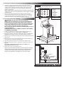
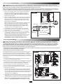
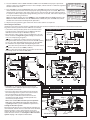
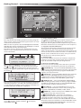
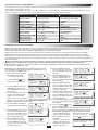
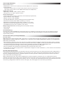
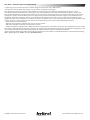
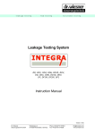
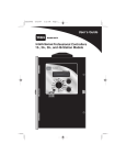
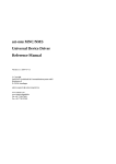
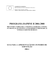
Installation and Getting Started Guide
Selecting the Controller Installation Site
The Eagle Plus controller in wall-mount cabinet is designed for indoor or outdoor environments, whereas pedestalmount models are specifically designed for outdoor installation. Regardless of the enclosure type, selecting an
installation site that provides user accessibility as well as basic protection from extreme hot or cold environments is
considered good installation practice. At minimum, the installation site should provide the following:
• Protection from direct exposure to irrigation spray, midday sun, and snow accumulation
• Access to all required wiring connections
• Access to a dedicated, single-phase AC power source.
Installing the Wall-mount Enclosure Controller (See Page. 2 for Pedestal-mount Controller Installation)
1. Unlock and open the cabinet door, then open the hinged control
panel. Position the controller on the wall at eye level, and mark
the top and bottom mounting screw locations. See Figure 1.
B
Figure 1
Note: Two stainless steel screws are provided for installation to a
wall stud. If installing the controller on masonry or drywall, use the
appropriate type screw anchors and fasteners. Install the screw
anchors at 83/4” (22,23cm) (A) on center.
Caution: All cabinet openings required for installation and
wiring are provided. Drilling or cutting through the cabinet
should be avoided. Metal chips and filings entering the cabinet
can damage internal components.
2. Install the top mounting screw (B) leaving a 1/4” (6,4mm) gap
between the screw head and wall.
3. Hang the controller on the mounting screw, ensuring the screw
is located at the top of the cabinet keyhole slot. Install the lower
mounting screw (C), then tighten both screws securely.
A
C
F1 +
F1 F2 +
F2 ET +
ET RN +
RN 24 V
24 V
Installing Electrical Conduit
COM
MV
PMP
Note: Electrical conduit installation must comply
with all applicable NEC and local electrical codes.
1. Remove wiring terminal block cover (1). Install
electrical conduit from the power source
circuit breaker panel to the controller location.
Attach conduit to bottom of cabinet using the
1/2” / 3/4” (13mm / 19mm) access opening (2).
2. For field wiring, attach 2” or 3” (51mm or
76mm) conduit to cabinet using center access
hole (3).
3. An additional 1/2” / 3/4” (13mm / 19mm) access
hole (4) is provided or auxiliary wiring.
Note: Install optional ProMax antenna using
access opening (5), and/or access opening (6)
for the iCentral antenna.
Figure 2
1
3
5
6
2
4
Connecting Input Power Wiring
WARNING: All electrical service installation components and methods must comply with NEC and local
electrical codes that apply. GFCI protection is required on all equipment operated in wet locations. Most codes
require a means in the fixed wiring of disconnecting the AC power mains with a mechanical contact separation of
at least 0.120” (3mm) in the line and the neutral poles. The connection wire must have insulation rating of 221°F
(105°C) minimum. CONFIRM THAT THE AC POWER SOURCE IS OFF PRIOR TO CONNECTING WIRES.
1. Ensure the power is disconnected at the source.
See Warning above.
2. Remove the terminal block cover, located below the
transformer.
3. Route the AC power and equipment ground wires through
electrical conduit into the controller.
4. Strip wire ends to expose 3/8” (9,5mm) bare copper wire.
5. Using a small flat-blade screwdriver, secure wires to the
terminal connectors as shown in Figure 3 and as follows:
Line (black) to L, Neutral (white) to N, and Equipment Ground
(green) to .
6. Install and secure terminal block cover.
Note: Do not apply power to the controller until all remaining
installation procedures have been completed
1
Figure 3
Installing the Pedestal-mount Enclosure Controller
1. Prepare a concrete mounting slab per the dimensions
Figure 4
shown in Figure 4. Use the provided template to properly
position four stainless mounting bolts and wiring access
conduit into slab. Allow concrete to harden sufficiently
before continuing.
Note: Although the SPED and PSB pedestal base footprints vary
slightly, the same mounting bolt pattern shown applies to both
11.5”
pedestal styles.
(29,2cm)
2. Unlock and raise pedestal lid to remove pedestal door.
Position the pedestal on the slab, aligning the mounting
bolts with the holes in the pedestal base. Place a stainless
washer and nut on each stud and tighten securely.
Connecting Input Power Wiring
1.
2.
3.
4.
5.
6.
7.
WARNING: All electrical service installation
components and methods must comply with NEC and
local electrical codes that apply. Most codes require a
means in the fixed wiring of disconnecting the AC power
mains with a mechanical contact separation of at least
0.120” (3mm) in the line and the neutral poles.
The connection wire must have insulation rating of 221°F
(105°C) minimum.
CONFIRM THAT THE AC POWER SOURCE IS OFF PRIOR
TO CONNECTING WIRES.
Install a conduit box to the base of the power supply unit
(1/2” NPT nipple) and 1” conduit (AC). See Figure 5.
Ensure the power is disconnected at the source. Confirm the
On/Off power toggle switch in the OFF (down) position.
Remove top screw from conduit box cover and position cover
to the side.
Route the AC power and equipment ground wires from the
source into the controller conduit box.
Strip wire ends to expose 3/8” (9,5mm) bare copper wire.
Using insulated wire splice connectors, connect the wires as
follows:
Line (Hot) to Black, Neutral (Common) to White, and
Equipment Ground to Green.
Close and secure conduit box cover.
Note: Internal component arrangement will vary per controller
model. All wiring connection procedures including AC power,
earth ground, station output, field auxiliary, and two-wire
decoder are applicable to all Eagle Plus controller models.
Mounting Bolts (4 places)
1” Conduit:
P
S1
S
S2
P/MV
G
D
A
P - Power
S - Sensor
P/ - Pump/
Master Valve
G - Ground
C - Decoder
A - Auxiliary
FRONT
2” Conduit:
14.5” (36,8cm)
S1 - Stations (1– 24)
S2 - Stations (25– 48)
6” (15cm)
8” 20cm)
28”
(71cm)
28”
(71cm)
Figure 5
Line
Neutral
Equipment
Ground
Connecting an Earth Ground
IMPORTANT: The provided surge protection components cannot properly function unless a low-resistance
connection to earth ground is provided. It is the responsibility of the installer to connect the Eagle Plus controller to
earth ground in compliance with all applicable NEC and local electrical codes.
Note: The grounding method described below utilizes a copper-clad ground rod electrode. Due to variables in soil composition
and terrain, additional and/or alternate ground electrode types may be required to achieve the required maximum resistance of
10 ohms. Contact a local Irritrol distributor for grounding methods recommended for the specific installation site.
1. Drive a 5/8” by 10’ (17mm x 3m) copper-clad steel rod
Figure 6
into well-moistened soil, not less than 8’ (2.5 m) or
more than 12’ (3.7 m) from the controller. The top of
the ground rod should be buried approximately 12”
(30.5cm) below grade.
2. Route a 6 AWG (13,0mm2) solid copper wire connected
to the earth ground device into the controller cabinet
through the access hole provided below the copper
ground lug. Insert and secure the copper wire to the
ground lug. See Figure 4.
Valve Box
Ground Lug
Note: To provide the most efficient path to earth ground,
route the ground wire between the ground rod and
controller with the least amount of bending possible.
There should be no tight radius bends, nicks or deep
scratches on the entire length of the wire.
Valve Box
12”
(30,5cm
3. For optimum connectivity, secure the ground wire
to the ground rod using a Cad-WeldTM (or equivalent)
metal-fusion connection method.
4. Using an earth-ground resistance tester; i.e., Meggor®
or equivalent, confirm the resistance reading between
the controller and ground rod is 10 ohms or less.
Note: Contact your local Irritrol distributor for assistance
in obtaining the earth ground-resistance test device.
Periodically retest the earth ground connection to
confirm thar resistance remains at 10 ohms or less.
Cad-Weld
Connector
(Typical for Wall and
Pedestal Enclosures)
6 AWG (10mm2 )
Bare Copper Wire
8–12’ (2.4–3,7m)
10’ (3m) Ground Rod
Connecting Field Wiring
Caution: The Eagle Plus transformer is rated at 24 VAC, 50 VA. The controller can be programmed to operate up
to 8 programs concurrently (one station per program), in addition to a master valve, and a pump relay – totaling 10
concurrent field output loads.* Each station output terminal is rated 24 VAC, 0.5A (max.) @ 77°F (25°C), and capable
of operating more than one valve solenoid (typically 2 or 3).* Ensure the current load on any output does not exceed
0.5A, and the total current load imposed on the controller does not exceed 1.5A. The controller will automatically
detect excessive current load and generate the appropriate alarm(s).
*The irrigation system hydraulic capacity must be also be capable of maintaining adequate volume and pressure for all
automatic and manual watering operations.
2
Field Common
Terminal
COM
Figure 7
1 2 3
Connecting Station Valves and Master Valve
The Eagle Plus features direct-insertion, quick-release wire
terminals for all low-voltage wire connections. Each field
output terminal accepts a 14–18 AWG (2,08mm2 – 0,823mm2)
solid-core wire in each of two connection ports – enabling
two field wires to be connected independently to one terminal position.
• For positive wire retention, remove insolation to expose
1/2 –5/8” (13–17mm) bare copper wire.
• After insertion into terminal block, pull lightly on each wire
to confirm positive retention. To release, depress the small
tab (nearest the wire) using a small blade screwdriver.
• Use waterproof connectors on all field wire splices to
prevent corrosion and possible short circuit.
• Ensure all exposed wiring inside the controller is taped back
and properly insulated.
1. Route a separate control wire from each station output
terminal and the Master Valve terminal (if applicable) to
the corresponding valve location. Using a waterproof wire
splice connector, attach the control wire to either valve
solenoid lead. See Figure 5.
2. Route field common wire(s) from the controller’s multiple
COM terminals as required to interconnect the remaining
lead of each valve solenoid to the field common circuit.
Note: To assist in identifying field wire connections using
24 VAC, see Identifying Field Wire Connections on page 7.
Station
Terminals
Field Common
Terminals
Station Valves
F1 +
F1 F2 +
F2 ET +
ET RN +
RN 24 V
24 V
COM
MV
PMP
COM
MV
Master Valve
Terminal
Master Valve
Connecting a Pump Control
Caution: Do not be connect the controller directly to the pump motor or starter. A 24 VAC isolation relay; i.e.,
Irritrol SR-1 Pump Start Relay (or equivalent), must be used to facilitate the pump control circuit connection.
1. Install a 24 VAC pump start or equivalent
isolation relay. Route and connect a control
wire and a common wire from the Pump
terminal of the Pump/Master Valve terminal
block to the relay. See Figure 8.
2. Connect the remaining pump wiring per
the instructions provided by the pump
equipment manufacturer.
Caution: If multiple controllers are
utilized within the irrigation system, do
not interconnect the controllers’ field
common, pump or master valve wires.
Damage to the controllers can result.
Figure 9
Pump Power
Source
F1 +
F1 F2 +
F2 ET +
ET RN +
RN 24 V
24 V
Relay - 24 VAC,
0.5A Max.
Pressure
Switch
(optional)
COM
MV
PMP
Pump/Master Valve
Terminal Block
Pump
Common
Pump
Note: Contact technical support at 1-800-777-1477 for information regarding multiple-controller wire connections.
Connecting Sensors
The Eagle Plus controller provides connection terminals for two flow sensors, a Rain Master Weather Center II or an
Irritrol Rain/Freeze sensor. Installation of this equipment must be made in accordance with the instructions provided
with each device. The wire connections to the controller are made per the diagram in Figure 7.
Caution: To prevent damage to the controller and/or
Figure 9
sensor equipment, turn off power to the controller prior
to connecting sensor wires.
F1 +
Installation Notes:
Flow Sensor #1
F1 • The sensor connection terminals accept 18–22 AWG
F2 +
Flow Sensor #2
F2 (0,8mm2–0,5mm2) solid-core copper wire. To enable
ET +
positive wire retention, insulation must be removed from
Weather Central
ET OR
the end of each wire to expose 3/8 –1/2” (10–13mm) bare
RN +
Rain Sensor
copper wire.
RN • Flow sensors and Weather Center II connection wires
24 V
24 VAC Sensor
24 V
Power Source
have specific polarity that must be maintained for proper
operation of these devices. Note the + /– indicators on each
sensor connection terminal and connect accordingly.
• The controller can support input from the Weather Central II weather station or an Irritrol rain or rain/freeze sensor. Both
sensor inputs cannot be used together.
• A jumper wire installed between the RN(+) and RN(–) terminals must not be removed unless a (normally-closed) rain sensor
is connected.
• Refer to the Eagle Plus User’s Guide for information regarding compatible flow sensors and corresponding setup parameters.
F1 +
F1 F2 +
F2 ET +
ET RN +
RN 24 V
24 V
COM
MV
PMP
Connecting a Two-Wire Decoder System
Programming the Decoders
Rain Master decoders are configured in 1-, 2-, and 4-station models, and as shipped from the factory, have no
pre-defined station assignments. In order to be recognized by the Eagle Plus controller, each station must be defined
as a either a station number from 1 to 200, a Master Valve control, or a Pump control. To facilitate decoder programming,
a quick-connect terminal block is provided on the Two-Wire Decoder module board. See Figure 8.
Note: The Eagle Plus enables the decoders to be temporarily
connected and programmed without disconnecting power.
Figure 10
Red
1. Insert the red and black decoder wires into the corresponding
Black
terminal block positions.
Power
2. Press the SETUP
key to display
Status
SETUP:
Status
LED
the SETUP menu. The CONTROLLER -CONTROLLER- -FLOWLED
–PROGRAM–
–COMM–
menu item is chosen by default.
–ET–
[TWO–WIRE]
Turn the Dial right five steps to
choose the TWO-WIRE menu option,
then press the Dial to select.
SETUP TWO-WIRE
3.The SETUP TWO-WIRE menu
[PROGRAM DECODER]
screen is displayed with PROGRAM
-SHOW STATIONSDECODER option chosen by default. -TESTPress the Dial to select. Status LEDs
on the decoder and decoder board will begin blinking to confirm communication.
4.The PROGRAM DECODER screen will be displayed with the NEW ADDRESS option
PROGRAM DECODER:
CURRENT ADDRESS:NONE
chosen.
NEW ADDRESS[NONE]
Note: In this example, NONE indicates that decoder station slot 1 (1 of 4 available slots) has
-1- OF 4 -PROGRAMno existing address.
5. To select a different decoder station slot number, turn the Dial to choose the slot
PROGRAM DECODER:
number, then press the Dial to select. Turn the Dial to display the preferred number, then CURRENT ADDRESS:NONE
NEW ADDRESS[NONE]
press the Dial to enter.
[2] OF 4 -PROGRAM3
6. Press the Dial to choose NEW ADDRESS: NONE. Turn the Dial to display the preferred
address, then press the Dial to enter. In this example, station number 12 will be assigned to
decoder station slot 2 of 4.
7. Turn the Dial to choose PROGRAM, then press the Dial to begin the procedure. Within
a few moments the results will be displayed. If programming was successful, OK will be
momentarily displayed in the upper right corner, and the next decoder station number
in sequence will be displayed. If programming was not successful, FAIL will be displayed
and an alarm will be generated.
Note: To clear the Alarm, press the HOME key, turn the Dial to choose ALARMS, then press the
Dial to view Alarm information. Turn the Dial to choose CLEAR, then press the Dial select. Check
decoder wire connections and repeat the procedure.
8. Repeat the programming procedure for all decoder stations as required.
PROGRAM DECODER:
CURRENT ADDRESS:NONE
NEW ADDRESS[012]
-2- OF 4 -PROGRAMPROGRAM DECODER:
CURRENT ADDRESS:NONE
NEW ADDRESS-012-2- OF 4 [PROGRAM]
PROGRAM DECODER: OK
CURRENT ADDRESS: FAIL
12
NEW ADDRESS-012-3- OF 4 [PROGRAM]
Connecting the Decoders
Installing a decoder system requires a different approach to field installation compared to a conventional multi-wire
irrigation control system. The main differences include:
• A two-wire cable provides power and communication
Straight Line System
Controller
signals from the controller to up to 100 decoders for
individual control of up to 202 field outputs.
Lightning
A
Arrestor
• The two-wire cable system can be configured in one of
three methods: straight line, grid or loop, as illustrated
in the accompanying diagrams:
A
Ground
A TW-LA-1 lightning arrestors must be connected
Electrode
throughout the two-wire path at intervals of 600’ (183m)
or less. The same grounding requirements as specified for
B
the controller are required for each lightning arrestor.
B The cable wire path from the furthest decoder to the
controller cannot exceed 5000’ (1.54km).
Decoder
C The cable wire length from the decoder to the valve
(or pump) must not exceed 100’ (30m).
C
Valve
Grid System
Loop System
A
A
A
C
C
A
A
B
B
Part No.
Description
Part No.
Description
• TW-CAB-14 – 14-gauge, two-wire direct-burial
communication cable (or equivalent) is required
TW-D-1
Single Valve Decoder
TW-SPLICE-14 Waterproof Wire Splice
for decoder connection.
TW-D-2
Dual Valve Decoder
TW-CAB-14
14-Gauge, 2-Wire,
TW-D-4
Quad Valve Decoder
Direct-Burial Cable
• Two-wire cable wire color polarity must be mainTW-LA-1
Lighting Arrestor
tained throughout the system and connected to
the corresponding controller terminals.
• All wire splices and field connections must be
TW-LA-1
Figure 11
insulated using TW-SPLICE-14 waterproof wire
TW-D-2
connectors (or equivalent).
Ground
Note: Refer to Two-Wire Decoder System SpecificaRod
tions page 8 for additional important information
regarding decoder system installation requirements.
Testing the Decoder System
The purpose of the test is to verify the functionality of
each decoder station and its associated valve solenoid.
TW-CAB-14
Alarm log entries can be generated to locate and
1/2”
resolve decoder system issues and/or archive the test
4“
(12.7mm)
results for later review. See Testing the 2-Wire Decoder
(101mm)
TW-SPLICE-14
System on page 7 for complete information.
4
Getting Started — Control Module Overview
3
ALARM
IRIGATION
1
SU 08:20:15A WK1
VALID PGM:14
2
[MAIN]
4
5
6
7
1- LCD Display
The large format LCD display presents all setup, programming, system control and monitoring functions in an interactive menu-driven format.
Note: To conserver power, the LCD backlight dims automatically after five minutes of inactivity. The backlight is restored
automatically with any controller input.
The Home screen is displayed by default when the controller is in the standby mode to provide basic controller
status information.
1
2
3
2-Screen Sequence Keys
The Next and Back screen sequence keys are tied
to the corresponding and arrow symbols when
displayed. Pressing the associated sequence key provides
forward or backward access through the screen sequence.
3-Irrigation and Alarm Monitors
The Irrigation LED monitor illuminates to indicate system
watering activity. The Alarm LED monitor illuminates
when a system Alarm is generated. The Alarm monitor will
remain on until the user clears all alarms. An audible alarm
option can be enabled that will “chirp” every six seconds
to indicate one or more pending alarms.
4
4- Selection Dial
The selection Dial is the main user-interface component,
providing a single rotary/push-button dial to select and
input all controller setup and operating features.
5-Direct Access Menu Keys
Direct access to each primary menu function is provided
by pressing the corresponding selection key as follows:
The top line of the Home screen provides the current
day 1 , time 2 , and week 1 or 2 of the two-week watering schedule 3 . When equipped the optional iCentral
modem, an antenna symbol with signal strength bars will
be shown 4 .
PROGRAM Key – Selects the MAIN PROGRAM menu.
Provides program-related options including: new program
setup, existing program review, program modification,
deletion, and copy functions.
SETUP Key – Selects the MAIN SETUP menu. Provides
setup menus for CONTROLLER operating preferences,
FLOW monitor setup, PROGRAM operating preferences,
COMM setup, ET setup, and TWO-WIRE system setup.
MANUAL Key – Selects the MANUAL OPERATIONS
menu enabling manual control including: single STATION
and MULTI-STATION operation, manual PROGRAM start/
stop and station sequence TEST functions.
The second line indicates the current number of configured
automatic programs: 1–8 or None for standard systems, or
1–16 or None for Two-Wire systems. When the controller is in
the Water Off mode, WATER OFF is displayed
REVIEW Key – Selects the REVIEW menu to access
controller software/firmware version and operating data
logged for: PROGRAMS, ALARMS, FLOW, and ET.
HOME Key – Returns directly to the HOME menu from
any location within the menu hierarchy.
6 -
5
6
7
The bottom line of the Home screen provides: Main menu
access 5 , pending number of alarms 6 , and display
sequence arrow(s) 7 .
5
WATER OFF Key – Terminates all automatic
watering activity. When selected, all current automatic
controller operation shuts down and remains off until
WATER OFF mode is released. The Water Off LED monitor
illuminates when the controller is in the WATER OFF mode.
7-Pro Max Remote Control Receptacle – Provides easy
connection for Pro Max receiver cable.
Selecting Controller Setup Options
The controller setup options determine how the controller displays and manages the various tasks required to control
and monitor your irrigation system.
A set of default controller setup and operating preferences is established on initial power-up. The table below lists the
various controller setup menu items, the available options and the factory default settings.
Setup Menu
Current Time
Current Date
Clock Format
Access Code
Program Stacking
Stacking Limits
Station Delay
Master Valve Config.
Units Format
Date Format
Odd/Even Days Off
Rain Days Off
Water Window
Audible Alarm
Option
Numeric Value, AM/PM
Alpha/Numeric
12- or 24-Hour
4-Digit Numeric
Yes or No
1 to 8 Programs
0–19 min, 0–59 sec
NC or NO
U.S. Standard or Metric
mm/dd/yy or dd/mm/yy
Yes or No
1–9 or None
0–24 Hours
On or Off
Default
12:00:00 a.m.
Thursday, 01/ 01/2009
12-Hour
0000
Yes
3 Programs
0 min, 0 sec
NC (normally closed)
U.S. Standard
mm/dd/yy
No
None
24 (12:00 a.m.–11:59 p.m.)
Off
Setting the Current Time and Date
Note: Synchronizing the controller with the current date and time should be accomplished first. The remaining settings can
be changed at any time. Some of the settings will influence corresponding programming and controller operations. These
features are explained in detail within the applicable portion of the User’s Guide.
Upon initial power-up and after the controller has been without power for an extended period of time, the SETUP
DATE/TIME screen is displayed by default. Enter the actual time and date per the following step-by-step procedure.
When you have completed this initial procedure, you will be familiar with the Eagle Plus menu structure and how the
multifunctional Dial allows you to easily navigate to select, change, adjust and enter the various controller programming
and setup options.
Important: All setup and programming selections must be entered (saved to memory) by pressing the Dial before
pressing any of the Direct Access keys. The controller will disregard any selection that has not been saved.
Note: An audible “chirp” tone is generated each time a valid Key or Dial entry is made. An invalid action is indicated by the chirp
tone four times in rapid succession.
Note: Menu items displayed between dashes can be selected.
Turn the Dial in either direction to choose (bracket) the menu
item, then press the Dial to select.
1. The controller will display
SETUP DATE/TIME:
the SETUP DATE/TIME
DATE:[01/01/09]
TIME:-12:00AMscreen upon power up.
FORMAT:-12 HOUR-
2. Press the Setup
key to
display the SETUP menu.
SETUP:
[CONTROLLER] –FLOW–
–PROGRAM–
–COMM–
–ET–
–TWO–WIRE–
4. Press the Dial to select the
SETUP CONTROLLER:
CONTROLLER menu. The
[DATE/TIME] –ACCESS–
–DELAY–
DATE/TIME option is chosen –STACK–
–MVALVE–
–MORE–
by default.
6. Press the Dial to select and SETUP DATE/TIME:
display the SETUP DATE/
DATE:[01/01/09]
TIME:-12:00AMTIME screen. The DATE
FORMAT:-12 HOURoption is chosen by default.
Note: In this example, date and time will be changed the
default setting to June 15, 2011, 2:45
7. Press the Dial – the Month
SETUP DATE/TIME:
digits (01) will begin flashing. DATE:[01/01/09]
TIME:-12:00AMFORMAT:-12 HOUR-
8. Turn the Dial to display the
current month (06 = June),
then press the Dial to enter
the change. The Day digits
(01) will begin flashing.
9. Turn the Dial to display
the current day (15), then
press the Dial to enter the
change. The Year digits (09)
will begin flashing.
SETUP DATE/TIME:
DATE:[06/01/09]
TIME:-12:00AMFORMAT:-12 HOUR-
SETUP DATE/TIME:
DATE:[06/15/09]
TIME:-12:00AMFORMAT:-12 HOUR-
6
10. Turn the Dial to display
SETUP DATE/TIME:
the current year (11), then DATE:[06/15/11]
press the Dial to enter the TIME:-12:00AMFORMAT:-12 HOURchange.
11. Turn the Dial right one
SETUP DATE/TIME:
step to choose Time, then DATE:-06/15/11TIME:[12:00AM]
press the Dial to select.
FORMAT:–12 HOUR–
The current hour digits will
begin flashing.
12. Turn the Dial to display
SETUP DATE/TIME:
the current hour (02:), then DATE:-06/15/11TIME:[02:00AM]
press the Dial to enter the FORMAT:–12 HOUR–
change. The minutes digits
will begin flashing.
13. Turn the Dial to display the SETUP DATE/TIME:
DATE:-06/15/11current minute (:45), then
press the Dial to enter the TIME:[02:45AM]
FORMAT:–12 HOUR–
change. The AM designator
will begin flashing.
14. Turn the Dial to display PM, SETUP DATE/TIME:
then press the Dial to enter DATE:-06/15/11TIME:[02:45PM]
the change.
FORMAT:–12 HOUR–
15. Press the Home
key to
exit the SETUP menu.
Note: The initial Alarms shown on the Home screen are
generated by default during the power-up process and
not indicative of a problem. Clear the Alarms as follows:
• Turn the Dial right one
TH 02:45:39P WK1
VALID PGM:NONE
step to choose ALARMS.
• Press the Dial to select
-MAIN- [ALARMS( 1)]
ALARMS.
• The cause of the alarm
TH 02:45:39P WK1
POWER RESTORED
will be displayed. Press
the Dial as needed to
[CLEAR]
clear the Alarm(s).
Identifying Field Wire Connections
Caution: The method of field wire identification by momentarily contacting a field control wire to an energized
output terminal can damage the solid-state components of the Eagle Plus controller, and must not be used.
An alternate similar method that can be used safely with the Eagle Plus is accomplished as follows:
4 Insert the control wire you wish to identify to station 1
terminal.
5. Turn the Dial right one step MANUAL OPERATIONS:
to choose START, then press STATION- 11:00the Dial to begin operation. RUNTIME-[START]
1. Press the MANUAL
MANUAL OPERATIONS:
key to display the MANUAL [STATION] -PROGRAM-MULTI STATIONOPERATIONS screen. The
-TESTmanual STATION option is
chosen by default
2. Press the Dial to select
MANUAL OPERATIONS:
STATION – the next
STATION[ 1]
RUNTIME-00:00MANUAL OPERATIONS
-STARTscreen in sequence will
be displayed. Station 1 is
selected by default.
3. Turn the Dial right one step
MANUAL OPERATIONS:
to choose the
STATION- 1RUNTIME[01:00]
RUN TIME value. Press
-STARTthe Dial to select the time
value– the hours digits will
begin flashing. Turn the Dial right one step to display
one hour (01:00). Press the Dial to enter– the minutes
digits will be selected. Simply press the Dial to enter
00 minutes for this procedure.
The Irrigation LED will
illuminate, and the remaining run time for STATION 1 will
begin counting down. Note the corresponding sprinkler
operation.
6. Deactivate Station 1 by
STATION: 1 00:59:45
pressing the Dial to toggle MVALVE:OFF PUMP:OFF
[STOP]
from START to STOP.
-NEXT- -PREVIOUS-
7. Remove the control wire, then repeat steps 4–6 to test
the remaining control wires as needed.
8. When finished press the
TH 02:45:39P WK1
HOME
key to return to
VALID PGM:NONE
the Home screen.
[MAIN]
Testing the Two-Wire Decoder System
The Two-Wire Decoder system test feature provides methods of testing the decoder installation to easily verify
communication, station assignment and operating status and log the results. The following test options are available:
• Single Station: Tests a selected Decoder station number.
• Find Decoders: Tests and displays all controller stations
with an associated decoder address.
• All Programmed: Tests all decoder stations with a
defined address (1–200, Master Valve or Pump).
• All Stations: Tests all decoder stations, Master Valve and
Pump controls.
• Alarm Logging Options: Test results can be logged as
Alarms indicating Pass and/or Fail as selected.
••Log Fail Alarm: When selected, a decoder station that
fails the test criteria will be logged.
••Log Pass Alarm: When selected, a decoder station that
passes the test criteria will be logged
Note: Only the Single Station Test procedure is provided in this
guide. Refer to the Eagle Plus user’s guide for Find Decoder,
All Stations and All Programmed test procedures.
5. Turn the Dial to choose the
LOG PASS option. The NO
option is selected by default.
To enable this function, turn
the Dial to display YES, then
press the Dial to enter.
6. Turn the Dial to choose
GO, then press the Dial
to continue.
7. The SINGLE STATION TEST
screen will be displayed
with STATION 1 chosen by
default. To change the station
selection, press the Dial to
select, turn the Dial to display
the preferred station number,
then press the Dial to enter.
Single Station Test Procedure
1. Press the SETUP
key to
display the SETUP menu.
Turn the Dial to choose the
TWO-WIRE option, then
press the Dial to select.
The SETUP TWO-WIRE
menu screen is displayed
with the PROGRAM
DECODER option chosen by
default.
2. Turn the Dial to choose the
TEST option, then press the
Dial to select.
SETUP TWO-WIRE TEST
TYPE-SINGLE STATIONLOG FAILURES-YESLOG PASS[ NO] -GO-
SETUP TWO-WIRE TEST
TYPE-SINGLE STATIONLOG FAILURES-YESLOG PASS-YES- [GO]
SINGLE STATION TEST
STATION[ 1]
-GO-
SINGLE STATION TEST
STATION[ 12]
-GO-
8. Turn the Dial to choose GO, SINGLE STATION TEST
then press the Dial to start STATION- 1the test.
[GO]
SETUP:
-CONTROLLER- -FLOW–PROGRAM–
–COMM–
–ET–
[TWO–WIRE]
9. The test results will be
SETUP TWO-WIRE TEST:
TESTING STATION: 12
displayed. Based on the
CURRENT: .18
Alarm Log options selected, TESTING
VERSION: 0
[STOP]
an alarm may be generated.
Note: To pause or stop the test, turn the Dial to choose
STOP, then press the Dial to pause the test. To resume the
test, press the Dial again. To terminate the test, press the
BACK
key.
SETUP TWO-WIRE
[PROGRAM DECODER]
-SHOW STATIONS-TEST-
SETUP TWO-WIRE
-PROGRAM DECODER-SHOW STATIONS[TEST]
10.Press the HOME
key to
WE 02:47:41P WK1
VALID PGM:NONE
return to the Home screen.
SETUP TWO-WIRE TEST
Turn the Dial to choose
3.The SETUP TWO-WIRE TEST TYPE[SINGLE STATION]
-MAIN-[ALARMS( 1)]
ALARMS, then press the Dial
LOG FAILURES-YESscreen is displayed with
to review the Alarm screen.
LOG PASS-YES- -GOSINGLE STATION test type
11.Turn the Dial to choose
06/16 WE 02:48:01P
chosen by default.
CLEAR, then press the Dial to STATION 12
SETUP TWO-WIRE TEST
DECODER FOUND
4. Turn the Dial to choose the TYPE-SINGLE STATIONclear the alarm.
[CLEAR]
LOG
FAILURES[
NO]
LOG FAILURES option. The
LOG PASS- NO- -GOYES option is selected by
Note: Clearing alarms removes the screen prompts and
default.
extinguishes the Alarm LED indicator. Logged alarm
To disable this function, turn the Dial to display NO, then
information is accessible from the REVIEW menu screen.
press the Dial to enter.
7
General Specifications
Cabinet Dimensions:
• Wall Mount: 11” W x 16” H x 5.625” D (27,9cm W x 40,6cm H x 14,29cm D)
• Pedestal Mount:
Style PSB: 16.5” W x 38” H x 17.25” D (41,9cm W x 96,5cm H x 43,8cm D)
Style SPED: 16” W x 34” H x 16” D (40,6cm W x 86,4cm H x 40,6cm D)
Temperature Range:
• Operating: +14°F to +140°F (-10°C to +60°C)
• Storage: -22°F to +149°F (-30°C to +65°C)
Power Specifications:
• Internal Transformer, Class 2, UL Listed, CSA Certified (or equivalent)
• Input: 120 VAC ± 10%, 50/60 Hz
• Output: 24 VAC ± 10%, 50/60 Hz
• GFI with On/Off Power Switch (pedestal enclosure models only)
• Maximum Load Per Station: 0.5A @ 24 VAC @ 77° (25°C)
• Maximum Load Per Master Valve: 0.5A @ 24 VAC @ 77°F (25°C)
• Maximum Load Per Pump Output: 0.5A @ 24 VAC @ 77°F (25°C)
• Total Maximum Load: 1.5A @ 24 VAC @ 77°F (25°C)
Output Surge Protection (excluding two-wire decoder models):
• 6KV common
• 1KV normal.
Controller Memory:
The Eagle Plus utilizes NVRAM (Non-volatile Random Access Memory) technology to protect all user-defined program
and setup data from loss in the event of a power failure. Time and date settings will be maintained without power for
approximately 30 days.
Two-wire Decoder System Specifications
Decoder Cable:
Note: Rain Master communication cable, TW-CAB-14, is recommended. Twisted-pair, polyethylene-jacketed communication
cable, and PVC-insulated, single-core “irrigation” wire is not proven to be reliable for Rain Master decoder system application,
and is NOT recommended.
•Two-conductor, 14-gauge, solid-core copper wire, double-jacketed insulation manufactured of high-density, sunlightresistant polyethylene or UF-B UL PVC with a minimum wall thickness of 060” (1.5mm). A protective outer sheath must
be manufactured of polyethylene or PVC material conforming to ICEA S-GL-402 or NEMA WC5, with
a minimum wall thickness of .045” (1,2mm) and approved for direct burial installation.
•All wire insulation and conductors must be fully intact and free of nicks or cuts.
•A minimum wire size of 14-gauge (2mm2) is required for straight-line cable installation; i.e., wire distance to the furthest
decoder not on a loop.
Decoder Cable Configuration
To provide the optimum power and communication for system operation, the recommended wire path configuration is
a continuous loop beginning and ending at the controller, and is often routed generally following the main water lines.
The loop configuration provides a redundant path for decoder operation, allowing the system to continue operation
even in the event of a damaged cable.
Other supported decoder cable path configurations include: straight line, looped, star, or a combination of these
methods. Separate branch paths can be tapped from the main loop, and are not required to feed back to the main trunk
line. A branch path can be configured as a loop, a star, or a single line. The Rain Master decoder system will function with
most wiring configurations when the correct wire type, size, and length of run are within specification.
FCC Rules - Electromagnetic Compatibility
•Lightning surge arrestors must be installed along the cable path every 600’ (183m).
•All field wire connections and splices must be made completely watertight.
This equipment generates and uses radio frequency energy and if not installed and used properly, that is, in strict
accordance with the manufacturer’s instructions, may cause interference to radio and television reception. It has been
type tested and found to comply with the limits for a FCC Class B computing device in accordance with the specifications
in Subpart J of Part 15 of FCC Rules, which are designed to provide reasonable protection against such interference in a
residential installation. However, there is no guarantee that interference will not occur in a particular installation. If this
equipment does cause interference to radio or television reception, which can be determined by turning the equipment off
and on, the user is encouraged to try to correct the interference by one or more of the following measures:
•Reorient the receiving antenna.
•Relocate the irrigation controller with respect to the receiver.
•Move the irrigation controller away from the receiver.
•Plug the irrigation controller into a different outlet so the irrigation controller and receiver are on different branch circuits.
If necessary, the user should consult the dealer or an experienced radio/television technician for additional suggestions. The
user may find the following booklet prepared by the Federal Communications Commission helpful:
“How to Identify and Resolve Radio-TV Interference Problems”. This booklet is available from the U.S. Government Printing
Office, Washington, DC 20402. Stock No. 004-000-00345-4.
© 2010 Irritrol www.irritrol.com
From Number 373-0551 Rev. B